EP3740686B1 - Système de fixation de vis en série sur des attaches - Google Patents
Système de fixation de vis en série sur des attaches Download PDFInfo
- Publication number
- EP3740686B1 EP3740686B1 EP20744669.1A EP20744669A EP3740686B1 EP 3740686 B1 EP3740686 B1 EP 3740686B1 EP 20744669 A EP20744669 A EP 20744669A EP 3740686 B1 EP3740686 B1 EP 3740686B1
- Authority
- EP
- European Patent Office
- Prior art keywords
- clips
- clench
- key
- plunger
- attachment system
- Prior art date
- Legal status (The legal status is an assumption and is not a legal conclusion. Google has not performed a legal analysis and makes no representation as to the accuracy of the status listed.)
- Active
Links
Images



Classifications
-
- B—PERFORMING OPERATIONS; TRANSPORTING
- B23—MACHINE TOOLS; METAL-WORKING NOT OTHERWISE PROVIDED FOR
- B23P—METAL-WORKING NOT OTHERWISE PROVIDED FOR; COMBINED OPERATIONS; UNIVERSAL MACHINE TOOLS
- B23P19/00—Machines for simply fitting together or separating metal parts or objects, or metal and non-metal parts, whether or not involving some deformation; Tools or devices therefor so far as not provided for in other classes
- B23P19/001—Article feeders for assembling machines
-
- B—PERFORMING OPERATIONS; TRANSPORTING
- B23—MACHINE TOOLS; METAL-WORKING NOT OTHERWISE PROVIDED FOR
- B23P—METAL-WORKING NOT OTHERWISE PROVIDED FOR; COMBINED OPERATIONS; UNIVERSAL MACHINE TOOLS
- B23P19/00—Machines for simply fitting together or separating metal parts or objects, or metal and non-metal parts, whether or not involving some deformation; Tools or devices therefor so far as not provided for in other classes
- B23P19/001—Article feeders for assembling machines
- B23P19/003—Escapement mechanisms used therewith
-
- B—PERFORMING OPERATIONS; TRANSPORTING
- B23—MACHINE TOOLS; METAL-WORKING NOT OTHERWISE PROVIDED FOR
- B23P—METAL-WORKING NOT OTHERWISE PROVIDED FOR; COMBINED OPERATIONS; UNIVERSAL MACHINE TOOLS
- B23P19/00—Machines for simply fitting together or separating metal parts or objects, or metal and non-metal parts, whether or not involving some deformation; Tools or devices therefor so far as not provided for in other classes
- B23P19/001—Article feeders for assembling machines
- B23P19/004—Feeding the articles from hoppers to machines or dispensers
-
- B—PERFORMING OPERATIONS; TRANSPORTING
- B23—MACHINE TOOLS; METAL-WORKING NOT OTHERWISE PROVIDED FOR
- B23P—METAL-WORKING NOT OTHERWISE PROVIDED FOR; COMBINED OPERATIONS; UNIVERSAL MACHINE TOOLS
- B23P19/00—Machines for simply fitting together or separating metal parts or objects, or metal and non-metal parts, whether or not involving some deformation; Tools or devices therefor so far as not provided for in other classes
- B23P19/001—Article feeders for assembling machines
- B23P19/006—Holding or positioning the article in front of the applying tool
-
- B—PERFORMING OPERATIONS; TRANSPORTING
- B23—MACHINE TOOLS; METAL-WORKING NOT OTHERWISE PROVIDED FOR
- B23P—METAL-WORKING NOT OTHERWISE PROVIDED FOR; COMBINED OPERATIONS; UNIVERSAL MACHINE TOOLS
- B23P19/00—Machines for simply fitting together or separating metal parts or objects, or metal and non-metal parts, whether or not involving some deformation; Tools or devices therefor so far as not provided for in other classes
- B23P19/04—Machines for simply fitting together or separating metal parts or objects, or metal and non-metal parts, whether or not involving some deformation; Tools or devices therefor so far as not provided for in other classes for assembling or disassembling parts
- B23P19/06—Screw or nut setting or loosening machines
-
- F—MECHANICAL ENGINEERING; LIGHTING; HEATING; WEAPONS; BLASTING
- F24—HEATING; RANGES; VENTILATING
- F24F—AIR-CONDITIONING; AIR-HUMIDIFICATION; VENTILATION; USE OF AIR CURRENTS FOR SCREENING
- F24F13/00—Details common to, or for air-conditioning, air-humidification, ventilation or use of air currents for screening
- F24F13/02—Ducting arrangements
- F24F13/0209—Ducting arrangements characterised by their connecting means, e.g. flanges
Definitions
- This invention relates to a serial screw attaching system on clips enabling the connection of screws with clips used for fixing ventilation ducts in ventilation and climatization industries.
- Ventilation ducts are very important for these sytems to work efficiently.
- Assembly clips are of great importance in fixing ventilation ducts to each other. And then there's the process of attaching assembly clips with press screws. For this process step there are machines manufactured working serially. But in this manufactured machines, the process of attaching press screws to clips, is taking high costs and long times.
- connection clip enabling the detachable connection of two pieces made of plastic, metal etc.
- connection clip set-up has been described. It's about a set-up containing the bearing where the connection clip is seated on; the connection clip to be connected with the said lower piece; fixing tab located on the upper piece enabling the said connection clip to be connected with the upper piece by locking on the said locking slot.
- the described product is used in fixing low-endurance parts in white goods and automative industries. It's not possible fort hem to be used in fixing metal and metal-like parts. But said systems don't involve a setting about serial attaching of clips and screws. Clips are attached to screws all manually in these systems.
- CN 203 266 472 U discloses a system suitable for serial screw attachment on clips, which involves a magnetic holder and a clench key.
- This invention is the development made in serial screw attachment system on clips and its' characteristic is being a low-cost new technology with a different design, low production time, high fixing performance and that enables clips and screws to be serially connected with each other.
- assembly clips are considered.
- the applicant provides the clips manufacturing with the help of these applications made. After the clips manufacturing process there's the process of clips being attached to the screws. At this stage the applicant introduces the product subject to invention which he provides serial attachment of screws to the clips.
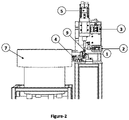
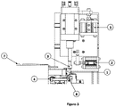
- the invention is consisting of a helically formed clip position changer (6), a servo motor (5) transferring rotary motion to the clench key (9), a first plunger (2) and a second plunger (3) enabling the clench key (9) to operate on two axis, a holder plate (8) properly positioning the screws coming from the screw setter unit (7) and enabling the magnetic holder (1) determine them and a third plunger (4) transferring forward and backward motion to the holder plate (8) ( Figure-1, Figure-2, Figure-3, Figure-4, Figure-5, Figure-6, Figure-7).
- the invention preferably involves the second plunger (3) that enables the screws to be attached to the clips by the clench key (9) rotating with the help of servo motor (5) and for this, moves the clench key (9) upwards and downwards ( Figure-1, Figure-2, Figure-3, Figure-4, Figure-6, Figure-7).
- the invention preferably involves a clip position changer (6) that enables clips holes for screws to be positioned as to come across with the head of the clench key (9), without a need for any extra action ( Figure -1, Figure -2, Figure -3, Figure -4, Figure -6, Figure -7).
- the invention preferably makes a 90 degrees difference between the angle of the clips where they enter the clip position changer (6) and where they reach the end of the clip position changer (6) ( Figure -1, Figure -6).
- the invention preferably involves the helically formed clip position changer (6) that enables clips to rotate 90 degrees ( Figure -1, Figure -6).
- the invention preferably involves a first plunger (2) that gains the clench key (9) a right-left motion ( Figure -1, Figure -2, Figure -3, Figure -4, Figure -6, Figure -7).
- the invention preferably involves the holder plate (8) that gets back to its' former position ( Figure -1, Figure -2, Figure -3, Figure -4, Figure -5, Figure -6).
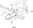
- the invention preferably involves the holder plate (8) which has a through gap (8.1) on itself ( Figure-5). While the holder plate (8) that has been moved forward by the third plunger (4) is at this position, the through gap (8.1) provides required area for the screws connected to the clench key (9) to move easily to come across with the top of the clip ( Figure -4, Figure -5).
- the invention preferably involves the slide (10) that enables the holder plate (8) to easily move forward and backward (Figure-5).
- the main elements involved in the invention are; the magnetic holder (1), the first plunger (2), the second plunger (3), the third plunger (4), the servo motor (5), clip position changer (6), the screw setter unit (7), the holder plate (8), the clench key (9) and the slide (10) ( Figure -1, Figure -2, Figure -3, Figure -4, Figure -5, Figure -6, Figure -7).
- the operating of the product subject to invention is as follows; first clips, more than one in quantity, are aligned on the clip position changer (6) ( Figure -1, Figure -6). As the clips move upon the clip position changer (6) they also change their angles ( Figure-1, Figure-6). There's a 90 degrees difference between the angle of the clip where it enters and where it reaches to the end of the clip position changer (6) ( Figure -1, Figure -6) Clip position changer (6) is manufactured in this way and it's a special design ( Figure - 1, Figure -6) When clips reaches to the end of the clip position changer (6) there's the clench key (9) right on top of the clips ( Figure -1, Figure -2, Figure -3, Figure -4, Figure -6, Figure -7). At this stage, keeping the clench key (9) at the proper distance is maintained by the upward-downward motion of the second plunger (3) ( Figure -1, Figure -2, Figure -3, Figure -4, Figure -6, Figure -7).
- Screws coming from the screw setter unit (7) are moving towards the screw holder plate (8) ( Figure-1, Figure-2, Figure-3, Figure-4, Figure-5, Figure-7).
- first plunger (2) moves the clench key (9) towards the holder plate (8) and the second plunger (3) moves downward ( Figure-1, Figure-2, Figure-3, Figure-4, Figure-5, Figure-6, Figure-7).
- the clench key (9) is being moved upward and downward by the second plunger (3) it's rotated by the servo motor (5) especially while being moved downward ( Figure-1, Figure-2, Figure-3, Figure-4, Figure-6, Figure-7).
- the first screw touching the holder plate (8) is holded by the magnetic holder (1) that's connected to the head of the clench key (9) ( Figure-1, Figure-2, Figure-3, Figure-4, Figure-5, Figure-6, Figure-7).
- the holder plate (8) is moved forward by the third plunger (4) upon the slide (10) ( Figure-1, Figure-2, Figure-3, Figure-4, Figure-5, Figure-6). While the holder plate (8) is on the forward direction, the screw taken by the clench key (9) easily passes through the through gap (8.1) located at the back of the holder plate (8) and is moved towards the screw hole on the clip.
- the holder plate (8) being moved forward by the third plunger (4), is taken back to its' former (initial) position to prevent the other screw to fall off ( Figure-1, Figure-2, Figure-3, Figure-4, Figure-5, Figure-6). In this way the screw is attached to the screw hole on the clip.
Landscapes
- Engineering & Computer Science (AREA)
- Mechanical Engineering (AREA)
- Details Of Spanners, Wrenches, And Screw Drivers And Accessories (AREA)
- Connection Of Plates (AREA)
- Branching, Merging, And Special Transfer Between Conveyors (AREA)
- Transmission Devices (AREA)
- Clamps And Clips (AREA)
Claims (10)
- Système de fixation par vis en série sur des clips qui comprend une retenue magnétique (1) et une clé de serrage (9), caractérisé en ce qu'il se compose des éléments suivants :- un changeur (6) de position de clip de forme hélicoïdale,- un servomoteur (5) qui transfère le mouvement rotatif à la clé de serrage (9),- un premier piston (2) et un deuxième piston (3) qui permet à la clé de serrage (9) de fonctionner sur deux axes,- une plaque de support (8) qui positionne correctement les vis provenant de l'unité (7) de régleur de vis et permet leur détermination par la retenue magnétique (1), et- un troisième piston (4) qui transfère le mouvement vers l'avant et vers l'arrière à la plaque de support (8).
- Système de fixation par vis en série sur des clips selon la revendication 1, caractérisé en ce qu'il implique le deuxième piston (3) qui permet aux vis d'être fixées aux clips par la clé de serrage (9) mise en rotation à l'aide du servomoteur (5) et pour cela, déplace la clé de serrage (9) vers le haut et vers le bas.
- Système de fixation par vis en série sur des clips selon la revendication 1, caractérisé en ce qu'il implique le changeur (6) de position de clip qui permet de positionner les trous des clips pour les vis de façon à ce qu'ils se croisent avec la tête de la clé de serrage (9), sans qu'aucune action supplémentaire ne soit nécessaire.
- Système de fixation par vis en série sur des clips selon la revendication 1, caractérisé en ce qu'une différence de 90 degrés est formée entre l'angle des clips où ils entrent dans le changeur (6) de position de clip et où ils atteignent l'extrémité du changeur (6) de position de clip.
- Système de fixation par vis en série sur des clips selon la revendication 1 ou la revendication 4, caractérisé en ce qu'il implique le changeur (6) de position de clip de forme hélicoïdale qui permet aux clips de tourner de 90 degrés.
- Système de fixation par vis en série sur des clips selon la revendication 1, caractérisé en ce qu'il implique le premier piston (2) qui confère à la clé de serrage (9) un mouvement droite-gauche.
- Système de fixation par vis en série sur des clips selon la revendication 1, caractérisé en ce qu'il implique la plaque de support (8) qui revient à sa position antérieure pour empêcher la vis qui vient de tomber en raison du mouvement vers l'avant du troisième piston (4).
- Système de fixation par vis en série sur des clips selon la revendication 1, caractérisé en ce qu'il implique la plaque de support (8) qui présente sur elle-même un espace traversant (8.1).
- Système de fixation par vis en série sur des clips selon la revendication 1 ou la revendication 8, caractérisé en ce qu'il implique l'espace traversant (8.1) qui fournit la surface requise pour que les vis reliées à la clé de serrage (9) se déplacent facilement pour venir en contact avec le haut du clip tandis que la plaque de support (8) qui a été déplacée vers l'avant par le troisième piston (4) est à cette position.
- Système de fixation par vis en série sur des clips selon la revendication 1, caractérisé en ce qu'il implique la glissière (10) qui permet à la plaque de support (8) de se déplacer facilement vers l'avant et vers l'arrière.
Applications Claiming Priority (2)
| Application Number | Priority Date | Filing Date | Title |
|---|---|---|---|
| TR2019/01044A TR201901044A2 (tr) | 2019-01-23 | 2019-01-23 | Kli̇pslere seri̇ şeki̇lde vi̇da takma si̇stemi̇nde yapilan geli̇şti̇rme |
| PCT/TR2020/050010 WO2020153926A2 (fr) | 2019-01-23 | 2020-01-08 | Développement réalisé dans un système de fixation de vis en série sur des attaches |
Publications (3)
| Publication Number | Publication Date |
|---|---|
| EP3740686A2 EP3740686A2 (fr) | 2020-11-25 |
| EP3740686A4 EP3740686A4 (fr) | 2021-11-24 |
| EP3740686B1 true EP3740686B1 (fr) | 2023-01-25 |
Family
ID=67956142
Family Applications (1)
| Application Number | Title | Priority Date | Filing Date |
|---|---|---|---|
| EP20744669.1A Active EP3740686B1 (fr) | 2019-01-23 | 2020-01-08 | Système de fixation de vis en série sur des attaches |
Country Status (4)
| Country | Link |
|---|---|
| EP (1) | EP3740686B1 (fr) |
| PL (1) | PL3740686T3 (fr) |
| TR (2) | TR201901044A2 (fr) |
| WO (1) | WO2020153926A2 (fr) |
Families Citing this family (1)
| Publication number | Priority date | Publication date | Assignee | Title |
|---|---|---|---|---|
| CN117283262A (zh) * | 2023-11-14 | 2023-12-26 | 重庆前卫表业有限公司 | 膜式燃气表机芯卡子装配机 |
Family Cites Families (10)
| Publication number | Priority date | Publication date | Assignee | Title |
|---|---|---|---|---|
| US4815206A (en) * | 1986-11-19 | 1989-03-28 | Ruvo Automation Corporation | Door hinge applicator |
| JPH03196926A (ja) * | 1989-12-23 | 1991-08-28 | Yoshitaka Aoyama | ねじ部品の供給締付け方法およびその装置 |
| DE202007010850U1 (de) * | 2007-08-03 | 2008-10-23 | Gebhardt-Stahl Gmbh | Vorrichtung zum Verspannen von Profilen an Lüftungskanälen |
| CN102729038B (zh) * | 2012-07-06 | 2014-09-24 | 闻金普 | 调整螺丝和螺母的全自动组合装配机 |
| CN203266472U (zh) * | 2013-04-26 | 2013-11-06 | 南通市华冠电器有限公司 | 自动拧螺钉机的拧螺钉工件定位装置 |
| CN204165193U (zh) * | 2014-10-15 | 2015-02-18 | 大连兆和科技发展有限公司 | 共板法兰风管安装卡件 |
| CN204248375U (zh) * | 2014-10-31 | 2015-04-08 | 金盛紧固技术(安徽)有限责任公司 | 一种喉箍螺钉装配机 |
| CN205437757U (zh) * | 2016-04-06 | 2016-08-10 | 浙江吉达金属有限公司 | 防螺丝卡嵌的全自动组合装配机 |
| CN206936792U (zh) * | 2017-04-26 | 2018-01-30 | 天津志信广博五金制品有限公司 | 一种螺母自动供料和拧紧装置 |
| CN207255645U (zh) * | 2017-07-28 | 2018-04-20 | 山西典石晨晶科技有限公司 | 一种螺丝自动上料装置 |
-
2019
- 2019-01-23 TR TR2019/01044A patent/TR201901044A2/tr unknown
- 2019-03-04 TR TR2019/03269A patent/TR201903269A2/tr unknown
-
2020
- 2020-01-08 EP EP20744669.1A patent/EP3740686B1/fr active Active
- 2020-01-08 WO PCT/TR2020/050010 patent/WO2020153926A2/fr not_active Ceased
- 2020-01-08 PL PL20744669.1T patent/PL3740686T3/pl unknown
Also Published As
| Publication number | Publication date |
|---|---|
| EP3740686A2 (fr) | 2020-11-25 |
| WO2020153926A3 (fr) | 2020-08-27 |
| PL3740686T3 (pl) | 2023-06-26 |
| TR201901044A2 (tr) | 2019-02-21 |
| WO2020153926A2 (fr) | 2020-07-30 |
| EP3740686A4 (fr) | 2021-11-24 |
| TR201903269A2 (tr) | 2019-03-21 |
Similar Documents
| Publication | Publication Date | Title |
|---|---|---|
| EP3740686B1 (fr) | Système de fixation de vis en série sur des attaches | |
| JP2009525184A (ja) | 鋭いエッジ有し、かつ、だれを低減した単段式設備における部材の精密打抜き方法及びその装置 | |
| US5259226A (en) | Mechanism for forming spring pitch | |
| CN101801577A (zh) | 用于便携式倒角机的倒角量调节装置 | |
| CN112427539A (zh) | 一种便于调节冲孔大小的薄板冲压设备及其调节方法 | |
| US7134305B2 (en) | Wire feeder driving mechanism for spring manufacturing machine | |
| CN211757909U (zh) | 一种汽车零部件加工冲床 | |
| CN108015135B (zh) | 一种钣金折弯定位工装 | |
| CN107231796B (zh) | 机床 | |
| CN114701248B (zh) | 用于空调器的丝印工装 | |
| CN104593955A (zh) | 一种自动缝纫机载料转盘模具的组合压板装配结构 | |
| US20020088319A1 (en) | Punch press and machining method of the punch press | |
| CN206169118U (zh) | 折弯机的弯模及折弯机 | |
| JP2003053463A (ja) | ばね製造機の線材折曲装置 | |
| CN111790780B (zh) | 一种薄铁皮异形件连续折弯机 | |
| JP2003094136A (ja) | 加工装置及びこれを利用して製造した熱交換器 | |
| CN206366627U (zh) | 一种新型八轴弹簧制造设备 | |
| CN207288595U (zh) | 快换紧凑自润滚轴斜楔机构 | |
| CN204893071U (zh) | 切割刀头组件及具有其的弯管机 | |
| CN106111841B (zh) | 折弯机 | |
| CN207669791U (zh) | 3d打印机及其快捷拆装喷头和快捷拆装组件 | |
| CN106564211B (zh) | 成型装置及其模板导向结构、导向方法 | |
| CN206344200U (zh) | 一种可计算机控制刀具行程的电路主板边缘倒角去料设备 | |
| CN100554711C (zh) | 一种二类轴承实体组合保持架支柱的加工方法 | |
| CN204589549U (zh) | 一种自动缝纫机载料转盘模具的组合压板装配结构 |
Legal Events
| Date | Code | Title | Description |
|---|---|---|---|
| STAA | Information on the status of an ep patent application or granted ep patent |
Free format text: STATUS: THE INTERNATIONAL PUBLICATION HAS BEEN MADE |
|
| PUAI | Public reference made under article 153(3) epc to a published international application that has entered the european phase |
Free format text: ORIGINAL CODE: 0009012 |
|
| STAA | Information on the status of an ep patent application or granted ep patent |
Free format text: STATUS: REQUEST FOR EXAMINATION WAS MADE |
|
| 17P | Request for examination filed |
Effective date: 20200820 |
|
| AK | Designated contracting states |
Kind code of ref document: A2 Designated state(s): AL AT BE BG CH CY CZ DE DK EE ES FI FR GB GR HR HU IE IS IT LI LT LU LV MC MK MT NL NO PL PT RO RS SE SI SK SM TR |
|
| AX | Request for extension of the european patent |
Extension state: BA ME |
|
| A4 | Supplementary search report drawn up and despatched |
Effective date: 20211025 |
|
| RIC1 | Information provided on ipc code assigned before grant |
Ipc: F24F 13/02 20060101ALI20211019BHEP Ipc: F16L 23/14 20060101ALI20211019BHEP Ipc: F16L 23/00 20060101ALI20211019BHEP Ipc: B23P 19/06 20060101ALI20211019BHEP Ipc: B23P 19/00 20060101ALI20211019BHEP Ipc: F16B 11/00 20060101AFI20211019BHEP |
|
| DAV | Request for validation of the european patent (deleted) | ||
| DAX | Request for extension of the european patent (deleted) | ||
| RIC1 | Information provided on ipc code assigned before grant |
Ipc: F24F 13/02 20060101ALI20220706BHEP Ipc: F16L 23/14 20060101ALI20220706BHEP Ipc: F16L 23/00 20060101ALI20220706BHEP Ipc: B23P 19/06 20060101ALI20220706BHEP Ipc: B23P 19/00 20060101ALI20220706BHEP Ipc: F16B 11/00 20060101AFI20220706BHEP |
|
| GRAP | Despatch of communication of intention to grant a patent |
Free format text: ORIGINAL CODE: EPIDOSNIGR1 |
|
| STAA | Information on the status of an ep patent application or granted ep patent |
Free format text: STATUS: GRANT OF PATENT IS INTENDED |
|
| INTG | Intention to grant announced |
Effective date: 20220830 |
|
| RIN1 | Information on inventor provided before grant (corrected) |
Inventor name: KIRANTAY, ALI LUETFUE Inventor name: DOGAN, YAVUZ |
|
| GRAS | Grant fee paid |
Free format text: ORIGINAL CODE: EPIDOSNIGR3 |
|
| GRAA | (expected) grant |
Free format text: ORIGINAL CODE: 0009210 |
|
| STAA | Information on the status of an ep patent application or granted ep patent |
Free format text: STATUS: THE PATENT HAS BEEN GRANTED |
|
| AK | Designated contracting states |
Kind code of ref document: B1 Designated state(s): AL AT BE BG CH CY CZ DE DK EE ES FI FR GB GR HR HU IE IS IT LI LT LU LV MC MK MT NL NO PL PT RO RS SE SI SK SM TR |
|
| REG | Reference to a national code |
Ref country code: GB Ref legal event code: FG4D |
|
| REG | Reference to a national code |
Ref country code: CH Ref legal event code: EP |
|
| REG | Reference to a national code |
Ref country code: AT Ref legal event code: REF Ref document number: 1546098 Country of ref document: AT Kind code of ref document: T Effective date: 20230215 Ref country code: IE Ref legal event code: FG4D |
|
| REG | Reference to a national code |
Ref country code: DE Ref legal event code: R096 Ref document number: 602020007884 Country of ref document: DE |
|
| REG | Reference to a national code |
Ref country code: RO Ref legal event code: EPE |
|
| REG | Reference to a national code |
Ref country code: SK Ref legal event code: T3 Ref document number: E 41266 Country of ref document: SK |
|
| REG | Reference to a national code |
Ref country code: LT Ref legal event code: MG9D |
|
| REG | Reference to a national code |
Ref country code: NL Ref legal event code: MP Effective date: 20230125 |
|
| REG | Reference to a national code |
Ref country code: AT Ref legal event code: MK05 Ref document number: 1546098 Country of ref document: AT Kind code of ref document: T Effective date: 20230125 |
|
| PG25 | Lapsed in a contracting state [announced via postgrant information from national office to epo] |
Ref country code: NL Free format text: LAPSE BECAUSE OF FAILURE TO SUBMIT A TRANSLATION OF THE DESCRIPTION OR TO PAY THE FEE WITHIN THE PRESCRIBED TIME-LIMIT Effective date: 20230125 |
|
| PG25 | Lapsed in a contracting state [announced via postgrant information from national office to epo] |
Ref country code: RS Free format text: LAPSE BECAUSE OF FAILURE TO SUBMIT A TRANSLATION OF THE DESCRIPTION OR TO PAY THE FEE WITHIN THE PRESCRIBED TIME-LIMIT Effective date: 20230125 Ref country code: PT Free format text: LAPSE BECAUSE OF FAILURE TO SUBMIT A TRANSLATION OF THE DESCRIPTION OR TO PAY THE FEE WITHIN THE PRESCRIBED TIME-LIMIT Effective date: 20230525 Ref country code: NO Free format text: LAPSE BECAUSE OF FAILURE TO SUBMIT A TRANSLATION OF THE DESCRIPTION OR TO PAY THE FEE WITHIN THE PRESCRIBED TIME-LIMIT Effective date: 20230425 Ref country code: LV Free format text: LAPSE BECAUSE OF FAILURE TO SUBMIT A TRANSLATION OF THE DESCRIPTION OR TO PAY THE FEE WITHIN THE PRESCRIBED TIME-LIMIT Effective date: 20230125 Ref country code: LT Free format text: LAPSE BECAUSE OF FAILURE TO SUBMIT A TRANSLATION OF THE DESCRIPTION OR TO PAY THE FEE WITHIN THE PRESCRIBED TIME-LIMIT Effective date: 20230125 Ref country code: HR Free format text: LAPSE BECAUSE OF FAILURE TO SUBMIT A TRANSLATION OF THE DESCRIPTION OR TO PAY THE FEE WITHIN THE PRESCRIBED TIME-LIMIT Effective date: 20230125 Ref country code: ES Free format text: LAPSE BECAUSE OF FAILURE TO SUBMIT A TRANSLATION OF THE DESCRIPTION OR TO PAY THE FEE WITHIN THE PRESCRIBED TIME-LIMIT Effective date: 20230125 Ref country code: AT Free format text: LAPSE BECAUSE OF FAILURE TO SUBMIT A TRANSLATION OF THE DESCRIPTION OR TO PAY THE FEE WITHIN THE PRESCRIBED TIME-LIMIT Effective date: 20230125 |
|
| PG25 | Lapsed in a contracting state [announced via postgrant information from national office to epo] |
Ref country code: SE Free format text: LAPSE BECAUSE OF FAILURE TO SUBMIT A TRANSLATION OF THE DESCRIPTION OR TO PAY THE FEE WITHIN THE PRESCRIBED TIME-LIMIT Effective date: 20230125 Ref country code: IS Free format text: LAPSE BECAUSE OF FAILURE TO SUBMIT A TRANSLATION OF THE DESCRIPTION OR TO PAY THE FEE WITHIN THE PRESCRIBED TIME-LIMIT Effective date: 20230525 Ref country code: GR Free format text: LAPSE BECAUSE OF FAILURE TO SUBMIT A TRANSLATION OF THE DESCRIPTION OR TO PAY THE FEE WITHIN THE PRESCRIBED TIME-LIMIT Effective date: 20230426 Ref country code: FI Free format text: LAPSE BECAUSE OF FAILURE TO SUBMIT A TRANSLATION OF THE DESCRIPTION OR TO PAY THE FEE WITHIN THE PRESCRIBED TIME-LIMIT Effective date: 20230125 |
|
| REG | Reference to a national code |
Ref country code: DE Ref legal event code: R097 Ref document number: 602020007884 Country of ref document: DE |
|
| PG25 | Lapsed in a contracting state [announced via postgrant information from national office to epo] |
Ref country code: SM Free format text: LAPSE BECAUSE OF FAILURE TO SUBMIT A TRANSLATION OF THE DESCRIPTION OR TO PAY THE FEE WITHIN THE PRESCRIBED TIME-LIMIT Effective date: 20230125 Ref country code: EE Free format text: LAPSE BECAUSE OF FAILURE TO SUBMIT A TRANSLATION OF THE DESCRIPTION OR TO PAY THE FEE WITHIN THE PRESCRIBED TIME-LIMIT Effective date: 20230125 Ref country code: DK Free format text: LAPSE BECAUSE OF FAILURE TO SUBMIT A TRANSLATION OF THE DESCRIPTION OR TO PAY THE FEE WITHIN THE PRESCRIBED TIME-LIMIT Effective date: 20230125 |
|
| PLBE | No opposition filed within time limit |
Free format text: ORIGINAL CODE: 0009261 |
|
| STAA | Information on the status of an ep patent application or granted ep patent |
Free format text: STATUS: NO OPPOSITION FILED WITHIN TIME LIMIT |
|
| 26N | No opposition filed |
Effective date: 20231026 |
|
| PG25 | Lapsed in a contracting state [announced via postgrant information from national office to epo] |
Ref country code: SI Free format text: LAPSE BECAUSE OF FAILURE TO SUBMIT A TRANSLATION OF THE DESCRIPTION OR TO PAY THE FEE WITHIN THE PRESCRIBED TIME-LIMIT Effective date: 20230125 |
|
| PG25 | Lapsed in a contracting state [announced via postgrant information from national office to epo] |
Ref country code: IT Free format text: LAPSE BECAUSE OF FAILURE TO SUBMIT A TRANSLATION OF THE DESCRIPTION OR TO PAY THE FEE WITHIN THE PRESCRIBED TIME-LIMIT Effective date: 20230125 |
|
| PG25 | Lapsed in a contracting state [announced via postgrant information from national office to epo] |
Ref country code: CZ Free format text: LAPSE BECAUSE OF NON-PAYMENT OF DUE FEES Effective date: 20240108 |
|
| PG25 | Lapsed in a contracting state [announced via postgrant information from national office to epo] |
Ref country code: CZ Free format text: LAPSE BECAUSE OF NON-PAYMENT OF DUE FEES Effective date: 20240108 |
|
| REG | Reference to a national code |
Ref country code: DE Ref legal event code: R119 Ref document number: 602020007884 Country of ref document: DE |
|
| PG25 | Lapsed in a contracting state [announced via postgrant information from national office to epo] |
Ref country code: MC Free format text: LAPSE BECAUSE OF FAILURE TO SUBMIT A TRANSLATION OF THE DESCRIPTION OR TO PAY THE FEE WITHIN THE PRESCRIBED TIME-LIMIT Effective date: 20230125 |
|
| PG25 | Lapsed in a contracting state [announced via postgrant information from national office to epo] |
Ref country code: MC Free format text: LAPSE BECAUSE OF FAILURE TO SUBMIT A TRANSLATION OF THE DESCRIPTION OR TO PAY THE FEE WITHIN THE PRESCRIBED TIME-LIMIT Effective date: 20230125 |
|
| REG | Reference to a national code |
Ref country code: CH Ref legal event code: PL |
|
| PG25 | Lapsed in a contracting state [announced via postgrant information from national office to epo] |
Ref country code: LU Free format text: LAPSE BECAUSE OF NON-PAYMENT OF DUE FEES Effective date: 20240108 |
|
| GBPC | Gb: european patent ceased through non-payment of renewal fee |
Effective date: 20240108 |
|
| PG25 | Lapsed in a contracting state [announced via postgrant information from national office to epo] |
Ref country code: LU Free format text: LAPSE BECAUSE OF NON-PAYMENT OF DUE FEES Effective date: 20240108 |
|
| PG25 | Lapsed in a contracting state [announced via postgrant information from national office to epo] |
Ref country code: DE Free format text: LAPSE BECAUSE OF NON-PAYMENT OF DUE FEES Effective date: 20240801 |
|
| PG25 | Lapsed in a contracting state [announced via postgrant information from national office to epo] |
Ref country code: GB Free format text: LAPSE BECAUSE OF NON-PAYMENT OF DUE FEES Effective date: 20240108 |
|
| PG25 | Lapsed in a contracting state [announced via postgrant information from national office to epo] |
Ref country code: BE Free format text: LAPSE BECAUSE OF NON-PAYMENT OF DUE FEES Effective date: 20240131 |
|
| PG25 | Lapsed in a contracting state [announced via postgrant information from national office to epo] |
Ref country code: FR Free format text: LAPSE BECAUSE OF NON-PAYMENT OF DUE FEES Effective date: 20240131 |
|
| PG25 | Lapsed in a contracting state [announced via postgrant information from national office to epo] |
Ref country code: CH Free format text: LAPSE BECAUSE OF NON-PAYMENT OF DUE FEES Effective date: 20240131 |
|
| REG | Reference to a national code |
Ref country code: SK Ref legal event code: MM4A Ref document number: E 41266 Country of ref document: SK Effective date: 20240108 |
|
| PG25 | Lapsed in a contracting state [announced via postgrant information from national office to epo] |
Ref country code: RO Free format text: LAPSE BECAUSE OF NON-PAYMENT OF DUE FEES Effective date: 20230125 Ref country code: GB Free format text: LAPSE BECAUSE OF NON-PAYMENT OF DUE FEES Effective date: 20240108 Ref country code: FR Free format text: LAPSE BECAUSE OF NON-PAYMENT OF DUE FEES Effective date: 20240131 Ref country code: DE Free format text: LAPSE BECAUSE OF NON-PAYMENT OF DUE FEES Effective date: 20240801 Ref country code: CH Free format text: LAPSE BECAUSE OF NON-PAYMENT OF DUE FEES Effective date: 20240131 Ref country code: BE Free format text: LAPSE BECAUSE OF NON-PAYMENT OF DUE FEES Effective date: 20240131 |
|
| REG | Reference to a national code |
Ref country code: BE Ref legal event code: MM Effective date: 20240131 |
|
| PG25 | Lapsed in a contracting state [announced via postgrant information from national office to epo] |
Ref country code: BG Free format text: LAPSE BECAUSE OF FAILURE TO SUBMIT A TRANSLATION OF THE DESCRIPTION OR TO PAY THE FEE WITHIN THE PRESCRIBED TIME-LIMIT Effective date: 20230125 |
|
| PG25 | Lapsed in a contracting state [announced via postgrant information from national office to epo] |
Ref country code: BG Free format text: LAPSE BECAUSE OF FAILURE TO SUBMIT A TRANSLATION OF THE DESCRIPTION OR TO PAY THE FEE WITHIN THE PRESCRIBED TIME-LIMIT Effective date: 20230125 |
|
| PG25 | Lapsed in a contracting state [announced via postgrant information from national office to epo] |
Ref country code: IE Free format text: LAPSE BECAUSE OF NON-PAYMENT OF DUE FEES Effective date: 20240108 |
|
| PG25 | Lapsed in a contracting state [announced via postgrant information from national office to epo] |
Ref country code: SK Free format text: LAPSE BECAUSE OF NON-PAYMENT OF DUE FEES Effective date: 20240108 |
|
| PG25 | Lapsed in a contracting state [announced via postgrant information from national office to epo] |
Ref country code: SK Free format text: LAPSE BECAUSE OF NON-PAYMENT OF DUE FEES Effective date: 20240108 Ref country code: IE Free format text: LAPSE BECAUSE OF NON-PAYMENT OF DUE FEES Effective date: 20240108 |
|
| PG25 | Lapsed in a contracting state [announced via postgrant information from national office to epo] |
Ref country code: CY Free format text: LAPSE BECAUSE OF FAILURE TO SUBMIT A TRANSLATION OF THE DESCRIPTION OR TO PAY THE FEE WITHIN THE PRESCRIBED TIME-LIMIT; INVALID AB INITIO Effective date: 20200108 |
|
| PG25 | Lapsed in a contracting state [announced via postgrant information from national office to epo] |
Ref country code: HU Free format text: LAPSE BECAUSE OF FAILURE TO SUBMIT A TRANSLATION OF THE DESCRIPTION OR TO PAY THE FEE WITHIN THE PRESCRIBED TIME-LIMIT; INVALID AB INITIO Effective date: 20200108 |
|
| PG25 | Lapsed in a contracting state [announced via postgrant information from national office to epo] |
Ref country code: PL Free format text: LAPSE BECAUSE OF NON-PAYMENT OF DUE FEES Effective date: 20240108 |
|
| PG25 | Lapsed in a contracting state [announced via postgrant information from national office to epo] |
Ref country code: TR Free format text: LAPSE BECAUSE OF FAILURE TO SUBMIT A TRANSLATION OF THE DESCRIPTION OR TO PAY THE FEE WITHIN THE PRESCRIBED TIME-LIMIT Effective date: 20230125 |