EP3740720B1 - Procédé et système de refroidissement dans la génération de chaleur par combustion - Google Patents
Procédé et système de refroidissement dans la génération de chaleur par combustion Download PDFInfo
- Publication number
- EP3740720B1 EP3740720B1 EP19709558.1A EP19709558A EP3740720B1 EP 3740720 B1 EP3740720 B1 EP 3740720B1 EP 19709558 A EP19709558 A EP 19709558A EP 3740720 B1 EP3740720 B1 EP 3740720B1
- Authority
- EP
- European Patent Office
- Prior art keywords
- heat
- cooling
- combustion
- refrigerating machine
- water circuit
- Prior art date
- Legal status (The legal status is an assumption and is not a legal conclusion. Google has not performed a legal analysis and makes no representation as to the accuracy of the status listed.)
- Active
Links
Images


Classifications
-
- F—MECHANICAL ENGINEERING; LIGHTING; HEATING; WEAPONS; BLASTING
- F24—HEATING; RANGES; VENTILATING
- F24D—DOMESTIC- OR SPACE-HEATING SYSTEMS, e.g. CENTRAL HEATING SYSTEMS; DOMESTIC HOT-WATER SUPPLY SYSTEMS; ELEMENTS OR COMPONENTS THEREFOR
- F24D3/00—Hot-water central heating systems
- F24D3/18—Hot-water central heating systems using heat pumps
-
- F—MECHANICAL ENGINEERING; LIGHTING; HEATING; WEAPONS; BLASTING
- F24—HEATING; RANGES; VENTILATING
- F24F—AIR-CONDITIONING; AIR-HUMIDIFICATION; VENTILATION; USE OF AIR CURRENTS FOR SCREENING
- F24F5/00—Air-conditioning systems or apparatus not covered by F24F1/00 or F24F3/00, e.g. using solar heat or combined with household units such as an oven or water heater
- F24F5/0007—Air-conditioning systems or apparatus not covered by F24F1/00 or F24F3/00, e.g. using solar heat or combined with household units such as an oven or water heater cooling apparatus specially adapted for use in air-conditioning
- F24F5/0014—Air-conditioning systems or apparatus not covered by F24F1/00 or F24F3/00, e.g. using solar heat or combined with household units such as an oven or water heater cooling apparatus specially adapted for use in air-conditioning using absorption or desorption
-
- F—MECHANICAL ENGINEERING; LIGHTING; HEATING; WEAPONS; BLASTING
- F24—HEATING; RANGES; VENTILATING
- F24F—AIR-CONDITIONING; AIR-HUMIDIFICATION; VENTILATION; USE OF AIR CURRENTS FOR SCREENING
- F24F5/00—Air-conditioning systems or apparatus not covered by F24F1/00 or F24F3/00, e.g. using solar heat or combined with household units such as an oven or water heater
- F24F5/0096—Air-conditioning systems or apparatus not covered by F24F1/00 or F24F3/00, e.g. using solar heat or combined with household units such as an oven or water heater combined with domestic apparatus
-
- F—MECHANICAL ENGINEERING; LIGHTING; HEATING; WEAPONS; BLASTING
- F25—REFRIGERATION OR COOLING; COMBINED HEATING AND REFRIGERATION SYSTEMS; HEAT PUMP SYSTEMS; MANUFACTURE OR STORAGE OF ICE; LIQUEFACTION SOLIDIFICATION OF GASES
- F25B—REFRIGERATION MACHINES, PLANTS OR SYSTEMS; COMBINED HEATING AND REFRIGERATION SYSTEMS; HEAT PUMP SYSTEMS
- F25B25/00—Machines, plants or systems, using a combination of modes of operation covered by two or more of the groups F25B1/00 - F25B23/00
- F25B25/02—Compression-sorption machines, plants, or systems
-
- F—MECHANICAL ENGINEERING; LIGHTING; HEATING; WEAPONS; BLASTING
- F25—REFRIGERATION OR COOLING; COMBINED HEATING AND REFRIGERATION SYSTEMS; HEAT PUMP SYSTEMS; MANUFACTURE OR STORAGE OF ICE; LIQUEFACTION SOLIDIFICATION OF GASES
- F25B—REFRIGERATION MACHINES, PLANTS OR SYSTEMS; COMBINED HEATING AND REFRIGERATION SYSTEMS; HEAT PUMP SYSTEMS
- F25B29/00—Combined heating and refrigeration systems, e.g. operating alternately or simultaneously
-
- F—MECHANICAL ENGINEERING; LIGHTING; HEATING; WEAPONS; BLASTING
- F24—HEATING; RANGES; VENTILATING
- F24D—DOMESTIC- OR SPACE-HEATING SYSTEMS, e.g. CENTRAL HEATING SYSTEMS; DOMESTIC HOT-WATER SUPPLY SYSTEMS; ELEMENTS OR COMPONENTS THEREFOR
- F24D2200/00—Heat sources or energy sources
- F24D2200/02—Photovoltaic energy
-
- F—MECHANICAL ENGINEERING; LIGHTING; HEATING; WEAPONS; BLASTING
- F24—HEATING; RANGES; VENTILATING
- F24D—DOMESTIC- OR SPACE-HEATING SYSTEMS, e.g. CENTRAL HEATING SYSTEMS; DOMESTIC HOT-WATER SUPPLY SYSTEMS; ELEMENTS OR COMPONENTS THEREFOR
- F24D2200/00—Heat sources or energy sources
- F24D2200/12—Heat pump
- F24D2200/123—Compression type heat pumps
-
- F—MECHANICAL ENGINEERING; LIGHTING; HEATING; WEAPONS; BLASTING
- F24—HEATING; RANGES; VENTILATING
- F24D—DOMESTIC- OR SPACE-HEATING SYSTEMS, e.g. CENTRAL HEATING SYSTEMS; DOMESTIC HOT-WATER SUPPLY SYSTEMS; ELEMENTS OR COMPONENTS THEREFOR
- F24D2200/00—Heat sources or energy sources
- F24D2200/12—Heat pump
- F24D2200/126—Absorption type heat pumps
-
- F—MECHANICAL ENGINEERING; LIGHTING; HEATING; WEAPONS; BLASTING
- F24—HEATING; RANGES; VENTILATING
- F24D—DOMESTIC- OR SPACE-HEATING SYSTEMS, e.g. CENTRAL HEATING SYSTEMS; DOMESTIC HOT-WATER SUPPLY SYSTEMS; ELEMENTS OR COMPONENTS THEREFOR
- F24D2200/00—Heat sources or energy sources
- F24D2200/16—Waste heat
- F24D2200/26—Internal combustion engine
-
- F—MECHANICAL ENGINEERING; LIGHTING; HEATING; WEAPONS; BLASTING
- F24—HEATING; RANGES; VENTILATING
- F24D—DOMESTIC- OR SPACE-HEATING SYSTEMS, e.g. CENTRAL HEATING SYSTEMS; DOMESTIC HOT-WATER SUPPLY SYSTEMS; ELEMENTS OR COMPONENTS THEREFOR
- F24D2200/00—Heat sources or energy sources
- F24D2200/32—Heat sources or energy sources involving multiple heat sources in combination or as alternative heat sources
-
- F—MECHANICAL ENGINEERING; LIGHTING; HEATING; WEAPONS; BLASTING
- F25—REFRIGERATION OR COOLING; COMBINED HEATING AND REFRIGERATION SYSTEMS; HEAT PUMP SYSTEMS; MANUFACTURE OR STORAGE OF ICE; LIQUEFACTION SOLIDIFICATION OF GASES
- F25B—REFRIGERATION MACHINES, PLANTS OR SYSTEMS; COMBINED HEATING AND REFRIGERATION SYSTEMS; HEAT PUMP SYSTEMS
- F25B27/00—Machines, plants or systems, using particular sources of energy
- F25B27/002—Machines, plants or systems, using particular sources of energy using solar energy
- F25B27/007—Machines, plants or systems, using particular sources of energy using solar energy in sorption type systems
-
- Y—GENERAL TAGGING OF NEW TECHNOLOGICAL DEVELOPMENTS; GENERAL TAGGING OF CROSS-SECTIONAL TECHNOLOGIES SPANNING OVER SEVERAL SECTIONS OF THE IPC; TECHNICAL SUBJECTS COVERED BY FORMER USPC CROSS-REFERENCE ART COLLECTIONS [XRACs] AND DIGESTS
- Y02—TECHNOLOGIES OR APPLICATIONS FOR MITIGATION OR ADAPTATION AGAINST CLIMATE CHANGE
- Y02B—CLIMATE CHANGE MITIGATION TECHNOLOGIES RELATED TO BUILDINGS, e.g. HOUSING, HOUSE APPLIANCES OR RELATED END-USER APPLICATIONS
- Y02B10/00—Integration of renewable energy sources in buildings
- Y02B10/70—Hybrid systems, e.g. uninterruptible or back-up power supplies integrating renewable energies
-
- Y—GENERAL TAGGING OF NEW TECHNOLOGICAL DEVELOPMENTS; GENERAL TAGGING OF CROSS-SECTIONAL TECHNOLOGIES SPANNING OVER SEVERAL SECTIONS OF THE IPC; TECHNICAL SUBJECTS COVERED BY FORMER USPC CROSS-REFERENCE ART COLLECTIONS [XRACs] AND DIGESTS
- Y02—TECHNOLOGIES OR APPLICATIONS FOR MITIGATION OR ADAPTATION AGAINST CLIMATE CHANGE
- Y02B—CLIMATE CHANGE MITIGATION TECHNOLOGIES RELATED TO BUILDINGS, e.g. HOUSING, HOUSE APPLIANCES OR RELATED END-USER APPLICATIONS
- Y02B30/00—Energy efficient heating, ventilation or air conditioning [HVAC]
- Y02B30/12—Hot water central heating systems using heat pumps
-
- Y—GENERAL TAGGING OF NEW TECHNOLOGICAL DEVELOPMENTS; GENERAL TAGGING OF CROSS-SECTIONAL TECHNOLOGIES SPANNING OVER SEVERAL SECTIONS OF THE IPC; TECHNICAL SUBJECTS COVERED BY FORMER USPC CROSS-REFERENCE ART COLLECTIONS [XRACs] AND DIGESTS
- Y02—TECHNOLOGIES OR APPLICATIONS FOR MITIGATION OR ADAPTATION AGAINST CLIMATE CHANGE
- Y02B—CLIMATE CHANGE MITIGATION TECHNOLOGIES RELATED TO BUILDINGS, e.g. HOUSING, HOUSE APPLIANCES OR RELATED END-USER APPLICATIONS
- Y02B30/00—Energy efficient heating, ventilation or air conditioning [HVAC]
- Y02B30/52—Heat recovery pumps, i.e. heat pump based systems or units able to transfer the thermal energy from one area of the premises or part of the facilities to a different one, improving the overall efficiency
-
- Y—GENERAL TAGGING OF NEW TECHNOLOGICAL DEVELOPMENTS; GENERAL TAGGING OF CROSS-SECTIONAL TECHNOLOGIES SPANNING OVER SEVERAL SECTIONS OF THE IPC; TECHNICAL SUBJECTS COVERED BY FORMER USPC CROSS-REFERENCE ART COLLECTIONS [XRACs] AND DIGESTS
- Y02—TECHNOLOGIES OR APPLICATIONS FOR MITIGATION OR ADAPTATION AGAINST CLIMATE CHANGE
- Y02P—CLIMATE CHANGE MITIGATION TECHNOLOGIES IN THE PRODUCTION OR PROCESSING OF GOODS
- Y02P80/00—Climate change mitigation technologies for sector-wide applications
- Y02P80/10—Efficient use of energy, e.g. using compressed air or pressurized fluid as energy carrier
- Y02P80/15—On-site combined power, heat or cool generation or distribution, e.g. combined heat and power [CHP] supply
Definitions
- the technical solution concerns a new method of central energy supply for built structures in the form of heat, service hot water, cold, and possibly also electric energy from a cogeneration unit.
- the new method makes it possible to use solar energy to support the cooling capacity.
- the system may be connected to already existing central heating distribution systems.
- Trigeneration systems where cooling is generated in addition to electric energy and heat, typically by means of an absorption refrigerating machine, are also known.
- Rising cooling capacity requirements are related not only to climate change and the associated air-conditioning of living spaces, but they are also influenced by needs to cool various technological spaces, such as server rooms, switchboards and the like. Requirements for the delivery of cooling capacity increase mainly in the summer months, although heat consumption is not equal to zero even during this period, heat is demanded mainly in the form of service hot water or for the heating of swimming pools and the like.
- Absorption refrigeration has three circuits, between which heat exchange takes place.
- the hot circulating water circuit is the driving medium of internal heat exchange and it can be connected to a cogeneration unit or another heat source.
- the second circuit is a cooling water circuit, which carries off the heat released by internal exchange. The cooling is most often done by means of cooling towers, which, however, represents essentially a heat loss.
- the third circuit is a cold water circuit, which delivers cooling capacity to the consumer, for example, for the cooling of premises.
- water refers to any liquid heat carrier, which does not have to be water in the literal meaning of the term or in the meaning of pure water.
- water is used in a broad sense in line with the terminology used in the heating industry.
- the system according to the publication US2017204806 describes a general arrangement of trigeneration with conventional compressor cooling, resulting in energy losses. Solutions according to CN105865083 , US2016223208 and PL398548 are suitable for the use of alternative sources and are not effectively usable in central heating as is typical of district CHP plants of housing estates.
- Publication EP1108964 describes a device, which has at least three heating medium circuits in addition to a load circuit.
- One heating medium circuit contains the absorbers and desorbers of all modules in series with a high temperature heat exchanger in a heat cell with an exhaust gas line and heated by a burner, a low temperature heat exchanger and a pump.
- the device has several modules. There are at least three heating medium circuits.
- a condensing exhaust gas heat exchanger is arranged in the exhaust gas line and is connected to one of the heating medium circuits.
- Cogeneration units typically work with a hot circulating water temperature gradient of 90/70 ° C and if the hot circulating water is supposed to drive the absorption refrigerating machine efficiently, it is heated up to at least 100°C, which is energy inefficient.
- the low temperature of the hot circulating water leads to a decrease in the mean logarithmic temperature difference and the absorption refrigerating machine works with less output.
- some trigeneration units use the split of the output of cooling units between absorption and compressor cooling, which increases the investment costs as well as space requirements for the placement of the system.
- the cooling water usually has a temperature of about 30 °C at the outlet of the absorption refrigerating machine, therefore its temperature is lower than the usual temperature of the return branch of the central heating system.
- the combustion heat source may be a heating boiler, in particular a gas boiler and/or a cogeneration unit.
- the new cooling method using an absorption refrigerating machine is not limited to a connection with a cogeneration unit, but is applicable for any heat source.
- the heat source has a hot circulating water outlet temperature of at least 80 °C, particularly preferably 90 °C, at which modern absorption refrigerating machines are operating with a good output.
- Connecting the cooling water circuit to the heat pump enables a very advantageous use of heat from the absorption refrigerating machine even though this cooling water circuit usually operates at low temperatures, for example with a temperature gradient of 30/35 °C or 25/30 °C. Due to the low temperatures, heat at such a temperature level has been considered waste heat and unusable heat so far. Connecting the cooling water circuit to the heat pump entails not only exploitation of this heat, but also a stabilization of the temperature conditions in the circuit.
- the desired temperature gradient for which the absorption refrigerating machine has been designed may be achieved not only by means of the heat pump control, but, where applicable, also by a three-way valve connected as a controlled bypass valve in the circuit between the cooling water outlet and the heat pump inlet.
- a heat store for example an accumulator tank, which is connected in the hot circulating water circuit and stabilizes the temperature conditions in cases of various fluctuations in the system, turned out to be an advantageous solution during the process of inventing.
- the accumulator tank has the advantage that the heat flow from other sources can be directed to it.
- Heat from solar panels more specifically heat from thermal solar panels or heat converted from the electric energy of photovoltaic panels, can be conducted to the accumulator tank.
- Photovoltaic panels can also produce electric energy for the distribution system together with the cogeneration unit.
- Circulating pumps are used, to achieve the necessary flows of heat transfer media, especially treated water. Circulating pumps enable to achieve the desired divergence of the water flow into the pipe branching from the main branch without the need for using a valve.
- Heat transfer media branches requiring physical separation may include heat exchangers.
- the heat exchanger will be connected, in particular, between the heat pump outlet and the central heat distribution system, between the heat outlet of cogeneration unit and the central heat distribution unit and the like.
- Controlled three-way valves by which the circuits can be bypassed, enable to control the desired temperature at the inlet to the connected element, for example at the absorption refrigerating machine inlet.
- a control unit for example in the form of a computer with the appropriate graphical interface, will preferably serve for joint control and alignment of their activities in the system according to this technical solution.
- Actuating units of the individual elements and devices such as gas boiler activation, circulating pump start, control of three-way valves, may be connected to the control unit and for its decision-making the control unit may receive information on the temperature and flow rates in various parts of the system.
- all the heat-transfer media branches will have temperature sensors both on the output and return side, which will enable calculation of the amount of heat transferred and used.
- the control unit may store values and control settings not only as statistical data, but these values and control settings may be also used to control the system to predict appropriate control.
- a system with variously dimensioned elements may be designed depending on the climatic conditions in the respective place of system implementation. For example, in the tropical zone, high cooling capacity will be required, therefore, a cogeneration unit covering the required electrical output will be used, the heat output required at the hot circulating water inlet of the absorption refrigerating machine, which goes beyond the waste heat of the cogeneration unit, will be covered by solar panels.
- the system will typically include a gas boiler as heat source.
- a connection in which the heat source is a gas boiler as well as a cogeneration unit is also possible; the start of these heat sources will be controlled according to the current needs of heat and electric energy. While preserving the main idea of the present technical solution, it is also possible to create a connection in which the boiler heats the water in the central distribution system and the cogeneration unit, using the waste heat, heats, drives the absorption refrigerating machine and at the same time transfers heat to the central distribution system depending on the excess of heat.
- the advantage of the technical solution is that it increases energy utilization. Not only is the original waste heat from cogeneration used for cooling and heating in the heat distribution system, but the secondary waste heat from the absorption refrigerating machine is also used for heating in the heat distribution system. Combustion of fuel in the boiler is primarily associated with heat generation, a cooling effect of the system is also created thanks to the absorption refrigerating machine, the waste heat from the absorption refrigerating machine being reused to support the useful heat output of the system.
- the heat distribution system 9 includes a conventional piping system with a primary and a return branch.
- the natural gas boiler 1 is used as the heat source in this example.
- the boiler 1 outlet is connected to the hot circulating water inlet of the absorption refrigerating machine 3 .
- the boiler 1 is set to maintain an output temperature of 90 °C. From the circulating water circuit, water exits the absorption refrigerating machine 3 with a temperature of about 70°C and enters the heat exchanger 6 , through which the heat is transferred to hot service water and in the winter period also to also to the heaters connected to the heat distribution system 9 .
- the accumulator tank 5 stabilizes the temperature conditions in the system in cases of fluctuations of the heat offtake in the distribution system 9 as well as in cases of differing power input of the absorption refrigerating machine 3 .
- the cooling water circuit through which heat is carried off from the absorption refrigerating machine 3 , is connected to the heat pump inlet 4 and the heat pump outlet 4 is connected to the return branch of the heat distribution 9 .
- the cooling water circuit operates with a temperature gradient of approximately 25/30 °C.
- the refrigerating machine 3 at its outlet in the cold water circuit, provides a temperature of 6 °C; after heat has been received in the server room, the water returns at a temperature of 12 °C.
- a three-way valve 10 is used to stabilize the temperature conditions in the cooling water circuit; the valve is controlled in such a way that the absorption refrigerating machine operates within the optimum temperature range for which it has been dimensioned.
- the individual elements of the system are products of various manufacturers.
- the absorption refrigerating machine 3 as well as the boiler 1 have their own process control in their interior.
- the control unit 11 is used for their external control and for mutual alignment of their outputs; the control unit simultaneously archives the measured values of temperatures and flow rates, based on which the delivered heat and heat taken off by cooling are calculated.
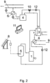
- the system with the connection according to figure 2 is supplemented with photovoltaic panels 8 , which produce electric energy.
- Electric energy is converted to alternating voltage of 240V by means of an inverter and it is used to drive circulating pumps in the system.
- the remainder of the energy from the photovoltaic panels 8 is converted to heat by an electric resistance coil located in the accumulator tank 5 .
- This example is a system applied in the island mode, where it generates electric energy, delivers heat to the central heating system and provides cooling capacity.
- the control unit 11 continuously evaluates the need for heat, cold and electric energy and activates the individual elements of the system accordingly.
- the main source of electricity is the cogeneration unit 2 , which, in this example, combusts natural gas.
- the electric energy from the cogeneration unit 2 is delivered for consumers connected to the system in the island mode.
- the heat outlet of the cogeneration unit 2 is connected to the hot circulating water inlet of the absorption refrigerating machine 3 .
- the waste heat from the cogeneration unit is then delivered to the heat distribution system 9 via the heat exchanger 6 .
- the heat exchanger 6 physically separates the media in heat exchange circuits.
- the preferred connection of the heat outlet from the cogeneration unit 2 to the inlet of hot circulating water of the absorption refrigerating machine 3 is related to the desired high temperature at the inlet of the absorption refrigerating machine 3; even after leaving the absorption refrigerating machine 3 , the water has a sufficiently high temperature for heat transfer to the central heat distribution system 9 .
- the absorption refrigerating machine 3 operates with a circuit of cooling water which has to be externally cooled, for example with a temperature gradient of 25/30 °C.
- a heat pump 4 is used for cooling; the heat pump uses the outlet of the cooling water circuit of the absorption refrigerating machine 3 as the inlet for obtaining heat.
- the outlet of the heat pump 4 which Is a water-water heat pump, is connected via the heat exchanger 6 to the return branch in the heat distribution system 9 . It is connected to the return branch because the return branch has a lower temperature and the heat transfer is faster.
- the system also includes a natural gas boiler 1 .
- thermal solar panels 7 deliver heat to storage tank 5 .
- the photovoltaic panels 8 produce electricity with a direct current which directs the electric resistance coil in the storage tank 5 or to an inverter that transforms electric energy into an AC voltage of 50 Hz.
- Temperature sensors located on the individual branches of the circuits are connected to the control unit 11 . Data on the flow rates in the individual circuit branches also go to the control unit 11 .
- the control unit 11 controls, through converters, the three-way valves 10 , circulation pumps 12 as well as the control of the boiler 1 and the cogeneration unit 2 according to the set rules and priorities for the island system.
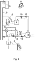
- the system includes a natural gas boiler 1 , which is the main heat source for the central heat distribution system 9 in the housing estate.
- the system also includes a cogeneration unit 2 connected to the public electricity grid.
- the cogeneration unit 2 combusts natural gas.
- the heat outlet of the cogeneration unit 2 is connected to the hot circulating water inlet of the absorption refrigerating machine 3 .
- the waste heat from the cogeneration unit is delivered to the heat distribution system 9 through the heat exchanger 6 .
- the absorption refrigerating machine 3 operates with a circuit of cooling water with a temperature gradient of 25/30 °C.
- a heat pump 4 is used for cooling; the heat pump uses the outlet of the cooling water circuit of the absorption refrigerating machine 3 as the inlet for obtaining heat.
- the outlet of the heat pump 4 is connected via the heat exchanger 6 to the return branch in the heat distribution system 9 .
- waste heat from the cogeneration unit 2 is used for heating and for preparing hot water. Not only is the original waste heat from cogeneration used for cooling and heating in the heat distribution system 9 , but also the secondary heat from the absorption refrigerating machine 3 is used for heating in the heat distribution system 9 .
Landscapes
- Engineering & Computer Science (AREA)
- Mechanical Engineering (AREA)
- General Engineering & Computer Science (AREA)
- Chemical & Material Sciences (AREA)
- Combustion & Propulsion (AREA)
- Physics & Mathematics (AREA)
- Thermal Sciences (AREA)
- Life Sciences & Earth Sciences (AREA)
- Sustainable Development (AREA)
- Heat-Pump Type And Storage Water Heaters (AREA)
- Sorption Type Refrigeration Machines (AREA)
Claims (15)
- Une méthode de refroidissement lors de la production de la chaleur par combustion, en particulier par combustion du combustible gazeux où le refroidissement est effectué à l'aide d'une machine frigorifique d' absorption (3), la dernière comportant trois circuits : a - un circuit d'eau chaude en circulation, b - un circuit d'eau de refroidissement, c - un circuit d'eau froide, étant donné que le circuit d'eau chaude en circulation (a) est relié à la source de chaleur de combustion ; à l'aide de la source de chaleur de combustion est chauffé l'eau dans le système de distribution de chauffage (9), et le circuit d'eau froide (c) fournit de la puissance frigorifique, et l'eau de refroidissement dans le circuit d'eau de refroidissement (b) s'écoule de la machine frigorifique d'absorption (3) vers une pompe à chaleur (4), et la pompe à chaleur (4) transfère la chaleur de l'eau de refroidissement à la branche de retour du système de distribution de chauffage (9).
- La méthode de refroidissement lors de la production de la chaleur par combustion selon la revendication 1, caractérisée en ce que la source de chaleur de combustion est une chaudière (1) et/ou une unité de cogénération (2).
- La méthode de refroidissement lors de la production de la chaleur par combustion selon la revendication 1 ou 2, caractérisée en ce que l'eau chaude circulant dans le circuit de la machine frigorifique d' absorption (3) a la température à l'entrée de 85 -95 °C et à la sortie de 65 - 75 °C, l'eau de refroidissement circulant entre la machine frigorifique d' absorption (3) et la pompe à chaleur (4) a une température de 23 - 27 °C à l'entrée la machine frigorifique d' absorption (3) et une température de 28 - 32 °C à la sortie la machine frigorifique d' absorption (3).
- Un système de refroidissement lors de la production de la chaleur par combustion, en particulier par combustion du combustible gazeux, comprend une source de chaleur de combustion, une pompe à chaleur (4), un système de distribution chauffage (9) et une machine frigorifique d'absorption (3) où le refroidissement est effectué par la machine frigorifique d' absorption (3), la dernière comportant trois circuits : a - un circuit d'eau chaude en circulation, b - un circuit d'eau de refroidissement, c - un circuit d'eau froide, étant donné que le circuit d'eau chaude en circulation (a) est relié à la source de chaleur de combustion ; à l'aide de la source de chaleur de combustion est chauffée l'eau dans le système de distribution de chauffage (9), et le circuit d'eau froide (c) fournit de la puissance frigorifique, et l'eau de refroidissement dans le circuit d'eau de refroidissement (b) est reliée à la pompe à chaleur (4), et la pompe à chaleur (4) est reliée à la branche de retour du système de distribution de chauffage (9).
- Le système de refroidissement lors de la production de la chaleur par combustion selon la revendication 4, caractérisé en ce qu' entre la pompe à chaleur (4) et le système de distribution de chauffage (9), un échangeur de chaleur (6) est inclus.
- Le système de refroidissement lors de la production de la chaleur par combustion selon la revendication 4 ou 5, caractérisé en ce qu'il comprend au moins une pompe de circulation (12), une vanne à trois voies (10) et une pompe de circulation dans le circuit d'eau de refroidissement, la pompe de circulation étant disposée sur le côté de la machine frigorifique d' absorption (3) en amont de la vanne à trois voies (10).
- Le système de refroidissement lors de la production de la chaleur par combustion selon quelconque des revendications 4 à 6, caractérisé en ce qu'il comprend un réservoir d'accumulation (5), le réservoir d'accumulation (5) est relié à la source de chaleur de combustion, de préférence à la chaudière (1).
- Le système de refroidissement lors de la production de la chaleur par combustion selon quelconque des revendications 4 à 7, caractérisé en ce que la sortie de la source de chaleur est connectée au système de distribution de chauffage (9) par échangeur de chaleur (6).
- Le système de refroidissement lors de la production de la chaleur par combustion selon quelconque des revendications 4 à 8, caractérisé en ce qu'il comprend un panneau solaire (7), qui est relié au système de distribution de chauffage (9) ou au réservoir d'accumulation (5).
- Le système de refroidissement lors de la production de la chaleur par combustion selon quelconque des revendications 4 à 9, caractérisé en ce qu'il comprend un panneau photovoltaïque (8) pouvant être connecté à l' armoire électrique et/ou à l' élément chauffant dans le réservoir d'accumulation (5).
- Le système de refroidissement lors de la production de la chaleur par combustion selon quelconque des revendications 4 à 10, caractérisé en ce que la source de chaleur de combustion est une unité de cogénération (2) dont la sortie électrique peut être connectée à l'armoire électrique et dont la sortie de chaleur est connectée au circuit d'eau chaude (a) et est composé d'une pompe de circulation (12) et d'une vanne à trois voies (10), le circuit d'eau chaude étant connecté à la machine frigorifique d' absorption (3).
- Le système de refroidissement lors de la production de la chaleur par combustion selon quelconque des revendications 4 à 11, caractérisé en ce que la source de chaleur de combustion est une chaudière (1) connectée par circuit d'eau chaude à l'entrée de la machine frigorifique d'absorption (3), et la sortie de la machine frigorifique d'absorption (3) est reliée par circuit d'eau chaude à l'entrée de la chaudière (1), et de préférence, l'échangeur de chaleur (6) connecté au système de distribution de chauffage (9), est placé dans le circuit d'eau chaude entre la sortie de la machine frigorifique d' absorption (3) et l'entrée de la chaudière (1).
- Le système de refroidissement lors de la production de la chaleur par combustion selon quelconque des revendications 4 à 12, caractérisé en ce que le combustible de la source de chaleur de combustion est le gaz naturel.
- Le système de refroidissement lors de la production de la chaleur par combustion selon quelconque des revendications 4 à 13, caractérisé en ce qu'il dispose d'une unité de commande (11) reliée à la commande de la machine frigorifique d' absorption (3), à la commande de la source de chaleur de combustion et relié à au moins une pompe de circulation (12), de préférence à au moins une vanne à trois voies (10).
- Le système de refroidissement lors de la production de la chaleur par combustion selon la revendication 14, caractérisé en ce que des capteurs de température sont prévus sur les branches d' a moins d'un circuit d'eau et connectés à l'unité de commande (11) et des capteurs de débit sur au moins une branche du circuit d'eau sont prévus et connectés à l'unité de commande (11), de préférence sur une branche de chaque circuit d'eau.
Applications Claiming Priority (2)
| Application Number | Priority Date | Filing Date | Title |
|---|---|---|---|
| SK50006-2018U SK8540Y1 (sk) | 2018-01-18 | 2018-01-18 | Spôsob a systém chladenia pri výrobe tepla spaľovaním |
| PCT/IB2019/050415 WO2019142138A1 (fr) | 2018-01-18 | 2019-01-18 | Procédé et système de refroidissement dans la génération de chaleur par combustion |
Publications (3)
| Publication Number | Publication Date |
|---|---|
| EP3740720A1 EP3740720A1 (fr) | 2020-11-25 |
| EP3740720B1 true EP3740720B1 (fr) | 2025-05-28 |
| EP3740720C0 EP3740720C0 (fr) | 2025-05-28 |
Family
ID=65686904
Family Applications (1)
| Application Number | Title | Priority Date | Filing Date |
|---|---|---|---|
| EP19709558.1A Active EP3740720B1 (fr) | 2018-01-18 | 2019-01-18 | Procédé et système de refroidissement dans la génération de chaleur par combustion |
Country Status (4)
| Country | Link |
|---|---|
| EP (1) | EP3740720B1 (fr) |
| HU (1) | HUE072551T2 (fr) |
| SK (1) | SK8540Y1 (fr) |
| WO (1) | WO2019142138A1 (fr) |
Families Citing this family (3)
| Publication number | Priority date | Publication date | Assignee | Title |
|---|---|---|---|---|
| CN112413556A (zh) * | 2020-11-10 | 2021-02-26 | 华鼎电源(天津)有限公司 | 一种热电联产燃气发电机优化系统及方法 |
| CN114857685A (zh) * | 2021-01-20 | 2022-08-05 | 宁波方太厨具有限公司 | 一种吸收式制冷厨房空调系统 |
| ES2902039A1 (es) * | 2021-12-29 | 2022-03-24 | Vano Josep Francesc Beneyto | Nueva aerotermia fotovoltaica |
Family Cites Families (8)
| Publication number | Priority date | Publication date | Assignee | Title |
|---|---|---|---|---|
| FR2309806A1 (fr) * | 1974-12-20 | 1976-11-26 | Chausson Usines Sa | Dispositif de pompe a chaleur pour le conditionnement, notamment le chauffage de locaux |
| FR2509443A1 (fr) * | 1981-07-11 | 1983-01-14 | Volkswagenwerk Ag | Montage avec pompe a chaleur a fonctionnement bivalent en parallele comprenant un bruleur qui produit des fumees |
| WO1983002820A1 (fr) * | 1982-02-03 | 1983-08-18 | Söllner, Robert | Dispositif de chauffage ou de refroidissement |
| DE19740398C2 (de) * | 1997-09-09 | 1999-12-02 | Vng Verbundnetz Gas Ag | Kraft-Wärme-gekoppelte Einrichtung zur Energieversorgung |
| DE19834696A1 (de) * | 1998-07-31 | 2000-02-10 | Ufe Solar Gmbh | Chemische Wärmepumpe, Sorptionsreaktor für eine chemische Wärmepumpe und Verfahren zur Wärmebedarfsdeckung und Klimatisierung von Gebäuden mittels einer chemischen Wärmepumpe |
| AT408913B (de) * | 1999-12-13 | 2002-04-25 | Vaillant Gmbh | Adsorptionswärmepumpe |
| DK1288596T3 (da) * | 2001-08-24 | 2008-02-04 | Vaillant Gmbh | Reguleringsfremgangsmåde til en adsorptionsvarmepumpe |
| WO2011054383A1 (fr) * | 2009-11-04 | 2011-05-12 | Aeteba Gmbh | Unité de refroidissement compacte |
-
2018
- 2018-01-18 SK SK50006-2018U patent/SK8540Y1/sk unknown
-
2019
- 2019-01-18 WO PCT/IB2019/050415 patent/WO2019142138A1/fr not_active Ceased
- 2019-01-18 HU HUE19709558A patent/HUE072551T2/hu unknown
- 2019-01-18 EP EP19709558.1A patent/EP3740720B1/fr active Active
Also Published As
| Publication number | Publication date |
|---|---|
| HUE072551T2 (hu) | 2025-11-28 |
| SK500062018U1 (sk) | 2019-04-02 |
| EP3740720A1 (fr) | 2020-11-25 |
| WO2019142138A1 (fr) | 2019-07-25 |
| EP3740720C0 (fr) | 2025-05-28 |
| SK8540Y1 (sk) | 2019-09-03 |
Similar Documents
| Publication | Publication Date | Title |
|---|---|---|
| US11371720B2 (en) | Thermal energy network and methods of providing thermal energy | |
| Mammoli et al. | Energetic, economic and environmental performance of a solar-thermal-assisted HVAC system | |
| EP3134685B1 (fr) | Système de chauffage et de refroidissement urbain à large bande | |
| US10455746B2 (en) | Hybrid cooling system having a Freon heat exchanger | |
| EP3740720B1 (fr) | Procédé et système de refroidissement dans la génération de chaleur par combustion | |
| WO2009114169A2 (fr) | Système de refroidissement, de chauffage et d’alimentation, doté d’un refroidisseur redondant actif à charge partielle | |
| KR102171919B1 (ko) | 결합된 냉각 및 가열 시스템 | |
| KR102507123B1 (ko) | 태양광열과 공기열을 동시에 이용하는 냉난방 및 급탕 시스템 및 그의 운전 방법 | |
| CN105102897A (zh) | 内嵌加热太阳能热储热集热器 | |
| EP3708915B1 (fr) | Systeme de chauffage urbain et methode pour augmenter la puissance pour le consommateur | |
| EP3901525A1 (fr) | Système de distribution d'énergie locale, ensemble d'extraction de chaleur locale et procédés de commande associés | |
| US20150060016A1 (en) | Method for pooling thermal energy, and heat exchange loop system between industrial and tertiary sites | |
| EP3803217B1 (fr) | Système de chauffage et de refroidissement, procédé et utilisation du système correspondants | |
| EP2058607A2 (fr) | Pompe de chaleur géothermique | |
| KR101430590B1 (ko) | 저수조용 냉각시스템 | |
| US20250244056A1 (en) | Energy efficient heating/cooling module | |
| US4328674A (en) | Power station | |
| US12152791B2 (en) | Efficiency for a heat extracting system and/or a heat depositing system | |
| KR102107097B1 (ko) | 지역 냉난방시스템 | |
| JP2015075321A (ja) | 貯湯式熱源装置及びその運転方法 | |
| EP4333237A1 (fr) | Module thermique et de puissance pour un bâtiment logistique | |
| RU2454608C1 (ru) | Способ горячего водоснабжения и способ отопления с его использованием | |
| RU2170885C1 (ru) | Система теплоэнергоснабжения | |
| KR101616053B1 (ko) | 수요처에 액상 냉매 노출 피해 방지 가능한 축열식 히트펌프 시스템 | |
| UA134069U (uk) | Автономна система підігріву води для гарячого водопостачання і/або опалення |
Legal Events
| Date | Code | Title | Description |
|---|---|---|---|
| STAA | Information on the status of an ep patent application or granted ep patent |
Free format text: STATUS: UNKNOWN |
|
| STAA | Information on the status of an ep patent application or granted ep patent |
Free format text: STATUS: THE INTERNATIONAL PUBLICATION HAS BEEN MADE |
|
| PUAI | Public reference made under article 153(3) epc to a published international application that has entered the european phase |
Free format text: ORIGINAL CODE: 0009012 |
|
| STAA | Information on the status of an ep patent application or granted ep patent |
Free format text: STATUS: REQUEST FOR EXAMINATION WAS MADE |
|
| 17P | Request for examination filed |
Effective date: 20200817 |
|
| AK | Designated contracting states |
Kind code of ref document: A1 Designated state(s): AL AT BE BG CH CY CZ DE DK EE ES FI FR GB GR HR HU IE IS IT LI LT LU LV MC MK MT NL NO PL PT RO RS SE SI SK SM TR |
|
| AX | Request for extension of the european patent |
Extension state: BA ME |
|
| DAV | Request for validation of the european patent (deleted) | ||
| DAX | Request for extension of the european patent (deleted) | ||
| STAA | Information on the status of an ep patent application or granted ep patent |
Free format text: STATUS: EXAMINATION IS IN PROGRESS |
|
| 17Q | First examination report despatched |
Effective date: 20230313 |
|
| GRAP | Despatch of communication of intention to grant a patent |
Free format text: ORIGINAL CODE: EPIDOSNIGR1 |
|
| STAA | Information on the status of an ep patent application or granted ep patent |
Free format text: STATUS: GRANT OF PATENT IS INTENDED |
|
| RIC1 | Information provided on ipc code assigned before grant |
Ipc: F25B 27/00 20060101ALN20241205BHEP Ipc: F25B 29/00 20060101ALI20241205BHEP Ipc: F25B 25/02 20060101ALI20241205BHEP Ipc: F24D 3/18 20060101ALI20241205BHEP Ipc: F24F 5/00 20060101AFI20241205BHEP |
|
| INTG | Intention to grant announced |
Effective date: 20241216 |
|
| RIN1 | Information on inventor provided before grant (corrected) |
Inventor name: POTASCH, TOMAS Inventor name: SZABO, ERNEST Inventor name: LUKOVICS, JULIUS Inventor name: KONCZER, JOZEF |
|
| GRAS | Grant fee paid |
Free format text: ORIGINAL CODE: EPIDOSNIGR3 |
|
| GRAA | (expected) grant |
Free format text: ORIGINAL CODE: 0009210 |
|
| STAA | Information on the status of an ep patent application or granted ep patent |
Free format text: STATUS: THE PATENT HAS BEEN GRANTED |
|
| AK | Designated contracting states |
Kind code of ref document: B1 Designated state(s): AL AT BE BG CH CY CZ DE DK EE ES FI FR GB GR HR HU IE IS IT LI LT LU LV MC MK MT NL NO PL PT RO RS SE SI SK SM TR |
|
| REG | Reference to a national code |
Ref country code: GB Ref legal event code: FG4D |
|
| REG | Reference to a national code |
Ref country code: CH Ref legal event code: EP |
|
| REG | Reference to a national code |
Ref country code: DE Ref legal event code: R096 Ref document number: 602019070504 Country of ref document: DE |
|
| REG | Reference to a national code |
Ref country code: IE Ref legal event code: FG4D |
|
| U01 | Request for unitary effect filed |
Effective date: 20250626 |
|
| U07 | Unitary effect registered |
Designated state(s): AT BE BG DE DK EE FI FR IT LT LU LV MT NL PT RO SE SI Effective date: 20250702 |
|
| PG25 | Lapsed in a contracting state [announced via postgrant information from national office to epo] |
Ref country code: ES Free format text: LAPSE BECAUSE OF FAILURE TO SUBMIT A TRANSLATION OF THE DESCRIPTION OR TO PAY THE FEE WITHIN THE PRESCRIBED TIME-LIMIT Effective date: 20250528 |
|
| PG25 | Lapsed in a contracting state [announced via postgrant information from national office to epo] |
Ref country code: NO Free format text: LAPSE BECAUSE OF FAILURE TO SUBMIT A TRANSLATION OF THE DESCRIPTION OR TO PAY THE FEE WITHIN THE PRESCRIBED TIME-LIMIT Effective date: 20250828 Ref country code: GR Free format text: LAPSE BECAUSE OF FAILURE TO SUBMIT A TRANSLATION OF THE DESCRIPTION OR TO PAY THE FEE WITHIN THE PRESCRIBED TIME-LIMIT Effective date: 20250829 |
|
| PG25 | Lapsed in a contracting state [announced via postgrant information from national office to epo] |
Ref country code: PL Free format text: LAPSE BECAUSE OF FAILURE TO SUBMIT A TRANSLATION OF THE DESCRIPTION OR TO PAY THE FEE WITHIN THE PRESCRIBED TIME-LIMIT Effective date: 20250528 |
|
| PG25 | Lapsed in a contracting state [announced via postgrant information from national office to epo] |
Ref country code: HR Free format text: LAPSE BECAUSE OF FAILURE TO SUBMIT A TRANSLATION OF THE DESCRIPTION OR TO PAY THE FEE WITHIN THE PRESCRIBED TIME-LIMIT Effective date: 20250528 |
|
| PG25 | Lapsed in a contracting state [announced via postgrant information from national office to epo] |
Ref country code: RS Free format text: LAPSE BECAUSE OF FAILURE TO SUBMIT A TRANSLATION OF THE DESCRIPTION OR TO PAY THE FEE WITHIN THE PRESCRIBED TIME-LIMIT Effective date: 20250828 |
|
| PG25 | Lapsed in a contracting state [announced via postgrant information from national office to epo] |
Ref country code: IS Free format text: LAPSE BECAUSE OF FAILURE TO SUBMIT A TRANSLATION OF THE DESCRIPTION OR TO PAY THE FEE WITHIN THE PRESCRIBED TIME-LIMIT Effective date: 20250928 |
|
| REG | Reference to a national code |
Ref country code: SK Ref legal event code: T3 Ref document number: E 47054 Country of ref document: SK |
|
| REG | Reference to a national code |
Ref country code: HU Ref legal event code: AG4A Ref document number: E072551 Country of ref document: HU |
|
| PG25 | Lapsed in a contracting state [announced via postgrant information from national office to epo] |
Ref country code: SM Free format text: LAPSE BECAUSE OF FAILURE TO SUBMIT A TRANSLATION OF THE DESCRIPTION OR TO PAY THE FEE WITHIN THE PRESCRIBED TIME-LIMIT Effective date: 20250528 |
|
| PLBE | No opposition filed within time limit |
Free format text: ORIGINAL CODE: 0009261 |
|
| STAA | Information on the status of an ep patent application or granted ep patent |
Free format text: STATUS: NO OPPOSITION FILED WITHIN TIME LIMIT |
|
| REG | Reference to a national code |
Ref country code: CH Ref legal event code: L10 Free format text: ST27 STATUS EVENT CODE: U-0-0-L10-L00 (AS PROVIDED BY THE NATIONAL OFFICE) Effective date: 20260409 |
|
| PGFP | Annual fee paid to national office [announced via postgrant information from national office to epo] |
Ref country code: SK Payment date: 20260113 Year of fee payment: 8 |