EP3741264A1 - Vorrichtung zum vorschub von waren - Google Patents
Vorrichtung zum vorschub von waren Download PDFInfo
- Publication number
- EP3741264A1 EP3741264A1 EP20160940.1A EP20160940A EP3741264A1 EP 3741264 A1 EP3741264 A1 EP 3741264A1 EP 20160940 A EP20160940 A EP 20160940A EP 3741264 A1 EP3741264 A1 EP 3741264A1
- Authority
- EP
- European Patent Office
- Prior art keywords
- slide
- guide
- marking element
- viewing window
- curved guide
- Prior art date
- Legal status (The legal status is an assumption and is not a legal conclusion. Google has not performed a legal analysis and makes no representation as to the accuracy of the status listed.)
- Granted
Links
Images



Classifications
-
- A—HUMAN NECESSITIES
- A47—FURNITURE; DOMESTIC ARTICLES OR APPLIANCES; COFFEE MILLS; SPICE MILLS; SUCTION CLEANERS IN GENERAL
- A47F—SPECIAL FURNITURE, FITTINGS, OR ACCESSORIES FOR SHOPS, STOREHOUSES, BARS, RESTAURANTS OR THE LIKE; PAYING COUNTERS
- A47F1/00—Racks for dispensing merchandise; Containers for dispensing merchandise
- A47F1/04—Racks or containers with arrangements for dispensing articles, e.g. by means of gravity or springs
- A47F1/12—Racks or containers with arrangements for dispensing articles, e.g. by means of gravity or springs dispensing from the side of an approximately horizontal stack
- A47F1/125—Racks or containers with arrangements for dispensing articles, e.g. by means of gravity or springs dispensing from the side of an approximately horizontal stack with an article-pushing device
- A47F1/126—Racks or containers with arrangements for dispensing articles, e.g. by means of gravity or springs dispensing from the side of an approximately horizontal stack with an article-pushing device the pushing device being urged by spring means
Definitions
- the present invention relates to a device for advancing goods, with a slide which can be moved along a guide profile and which is pretensioned by a spring in a feed direction in order to move goods to a stop on a front anchor, a marking element on the front anchor to indicate the filling level is provided.
- the DE 10 2013 104 023 A1 discloses a device for advancing goods in which a slide biases the goods towards a front stop.
- a slide biases the goods towards a front stop.
- an optical level indicator on a front anchor which is formed by a marking element.
- the marking element is coupled to the slide via a form-fitting connection and can therefore be moved together with it.
- This type of level indicator has proven itself, however, the guide profiles for moving the slide are offered in different lengths, so that the marking elements must also be provided in different lengths.
- the surrounding marking element requires numerous components that have to be assembled.
- a driver can be moved together with the slide and can be moved along a curved guide, the marking element being adjustable by the curved guide.
- a movement of the slide can be used to move the marking element to display the fill level.
- the level indicator can thus be produced with a few components and can be easily installed.
- the curved guide is preferably oriented at least partially inclined to the direction of movement of the slide.
- the curve guidance can thereby in Can be moved substantially perpendicular to the direction of movement of the slide for adjusting the marking element.
- the curve guide can be designed in the form of a strip and can be positioned movably, in particular displaceably, on the guide profile.
- the cam guide can, for example, have a groove-shaped guide track in order to receive a driver in the form of a pin or projection.
- the projection can optionally be fixed as a separate component on the slide or a component connected to the slide, or it can be formed integrally with the slide.
- the curved guide is preferably fixed on the guide profile in the direction of movement of the slide.
- the curved guide can have a holding section, for example on the marking element, in order to hold it on the front anchor in the direction of movement of the slide, that is to say in the longitudinal direction of the guide profile, and to be movable perpendicular to the direction of movement.
- the viewing window on the front anchor can have a transparent area in which the marking element is adjustably arranged. Adjacent to the transparent area, a non-transparent or closed area can be provided which covers the marking element, provided that sufficient goods are arranged in front of the slide.
- the cam guide can optionally be arranged over the entire length of the travel range of the slide or can be made shorter. If the curve guide is made shorter, the guide profile and curve guide can be produced independently of one another.
- the curve guide then preferably has an entry area in which the driver can be moved into and out of the guide track of the curve guide.
- the entry area can, for example, be designed as a funnel-shaped, groove-shaped guide track.
- a viewing window projecting from the stop to a front side and / or an opening is provided on the front anchor, at which a section of the marking element can be seen.
- the arrangement of the viewing window or a viewing opening in front of the stop has the advantage that the marking element is visible over a larger angular range. If a substantially plate-shaped viewing window is used, which is oriented vertically, the filling level can hardly be detected from above. In the case of shelves that are arranged at a low level in particular, it is advantageous for level monitoring if a level control is also essentially carried out can be done from above.
- the viewing window or an opening can be arranged in front of the stop.
- the viewing window is preferably partially curved and forms a receptacle for the marking element.
- the angular range from which the marking element can be seen in the transparent area of the viewing window is preferably at least 90 °, in particular at least 120 °.
- a device 1 for advancing goods comprises a guide profile 2 on which one or more webs 3 for guiding a slide 4 are formed.
- Two guide strips 6 are formed on the slide 4, each of which engages in a web 3 on the guide profile 2.
- the slide 4 comprises a plate-shaped contact surface 5 which is used to advance goods.
- a front anchor 7 is fixed to the guide profile 2 on a front side, on which a stop 8 is formed, which limits the movement of the respective foremost goods towards the front side.
- a viewing window 9 made of an at least partially transparent or translucent material, which enables filling level control.
- a curve guide 10 is arranged between the two webs 3, which is strip-shaped and a shorter length than that Has guide profile 2.
- the curved guide 10 comprises a groove-shaped guide track 16 which, on the end opposite the front anchor 7, has an entry area 17 which widens in a funnel-shaped manner.
- a spring 12 in a housing of the slide 4 which is designed as a band spring and is fixed with one end 13 to a holder 14 of the front anchor 7.
- the spring 12 biases the slide 4 in a feed direction 15 towards the front anchor 7, as symbolized by the arrow.
- a driver 11 in the form of a projection which engages in the groove-shaped guide track 16 on the curved guide 10.
- the cam guide 10 can be moved relative to the guide profile 3 via the driver 11 in order to adjust a marking element 18 which is arranged on the viewing window 9.
- the projection can also be attached directly to the slide 4.
- FIG 3 the slide 4 of the device is shown in an empty position, in which the slide 4 is arranged adjacent to the stop 8, so that only a few goods are provided between the contact surface 5 and the stop 8.
- the movement of the slide 4 along the guide track 16 has shifted the marking element 18 to a transparent area 21 of the viewing window 9.
- the viewing window 9 comprises an opaque area 20 and a transparent area 21.
- Figure 4 the slide 4 is shown in a position in which sufficient goods are still provided between the contact surface 5 and the stop 8.
- the marking element 18 has been shifted from the transparent area 21 to the opaque area 20, so that the marking element is now not or only slightly visible on the viewing window 9.
- the marking element 18 is adjusted on the viewing window 9, the marking element 18 being able to be moved continuously from the opaque area 20 to the transparent area 21.
- the fill level in front of the slide 4 can be displayed visually on the viewing window 9.
- an opening can also be provided through which the marking element 18 is visible.
- the viewing window 9 is located in front of the plate-shaped stop 8 in plan view, so that the viewing window 9 is also visible from above and not only from the front.
- the viewing window 9 is arched, for example over an angular range of around 90 °, so that the marking element 18 is visible within the viewing window 9 over an angular range of at least 90 °, preferably at least 120 °.
- the fill level can also be determined when viewing the viewing window 9 from above.
- the device 1 for advancing goods is shown in an exploded view.
- the strip-shaped curved guide 10 has a marking element 18 which is fixed in the longitudinal direction on the guide profile 2.
- the marking element 18 can have a downwardly open receptacle which is guided along a strip on the front anchor 7, so that the marking element 18 is movable essentially perpendicular to the longitudinal direction of the guide profile 2, but immovable on the front anchor in the longitudinal direction of the guide profile 2 7 is arranged.
- the cam guide 10 is formed in one piece. It is of course possible to assemble the marking element 18 and the curve guide 10 from several parts.
- the marking element 18 can also be designed differently, for example a movement of the marking element 18 when the slide 4 is moved in a direction other than perpendicular to the longitudinal direction of the guide profile 2.
- the viewing window 9 can also be made continuously transparent or have a filter so that the marking element 18 has a different color in a first area than in a second area.
- the marking element 18 can also have symbols to indicate the exact filling level numerically.
Landscapes
- Displays For Variable Information Using Movable Means (AREA)
- Freezers Or Refrigerated Showcases (AREA)
- A Measuring Device Byusing Mechanical Method (AREA)
Abstract
Description
- Die vorliegende Erfindung betrifft eine Vorrichtung zum Vorschub von Waren, mit einem entlang eines Führungsprofils verfahrbaren Schieber, der durch eine Feder in eine Vorschubrichtung vorgespannt ist, um Waren zu einem Anschlag an einem Frontanker zu bewegen, wobei ein Markierungselement an dem Frontanker zur Anzeige des Füllstandes vorgesehen ist.
- Die
DE 10 2013 104 023 A1 offenbart eine Vorrichtung zum Vorschub von Waren, bei der ein Schieber die Waren zu einem vorderen Anschlag vorspannt. Um zu sehen, welche Anzahl an Waren noch vor dem Schieber angeordnet ist, befindet sich an einem Frontanker eine optische Füllstandsanzeige, die durch ein Markierungselement gebildet ist. Das Markierungselement ist über eine formschlüssige Verbindung mit dem Schieber gekoppelt und somit zusammen mit diesem bewegbar. Diese Art der Füllstandsanzeige hat sich an sich bewährt, allerdings werden die Führungsprofile zum Verfahren des Schiebers in unterschiedlichen Längen angeboten, so dass auch die Markierungselemente in unterschiedlichen Längen bereitgestellt werden müssen. Zudem erfordert das umlaufende Markierungselement zahlreiche Bauteile, die montiert werden müssen. - Es ist daher Aufgabe der vorliegenden Erfindung, eine Vorrichtung zum Vorschub von Waren zu schaffen, die mit einfachen Mitteln eine Füllstandsanzeige ermöglicht.
- Diese Aufgabe wird mit einer Vorrichtung mit den Merkmalen des Anspruches 1 gelöst.
- Erfindungsgemäß ist ein Mitnehmer zusammen mit dem Schieber bewegbar und entlang einer Kurvenführung verfahrbar, wobei das Markierungselement durch die Kurvenführung verstellbar ist. Dadurch kann eine Bewegung des Schiebers genutzt werden, um das Markierungselement zur Anzeige des Füllstandes zu bewegen. Die Füllstandsanzeige kann somit mit wenigen Bauteilen hergestellt und einfach montiert werden.
- Vorzugsweise ist die Kurvenführung zumindest teilweise geneigt zur Bewegungsrichtung des Schiebers ausgerichtet. Die Kurvenführung kann dadurch im Wesentlichen senkrecht zur Bewegungsrichtung des Schiebers zum Verstellen des Markierungselementes bewegt werden. Die Kurvenführung kann leistenförmig ausgebildet sein und beweglich, insbesondere verschiebbar, an dem Führungsprofil positioniert werden. Die Kurvenführung kann beispielsweise eine nutförmige Führungsbahn aufweisen, um einen Mitnehmer in Form eines Stiftes oder Vorsprunges aufzunehmen. Der Vorsprung kann dabei wahlweise als separates Bauteil an dem Schieber oder einem mit dem Schieber verbundenen Bauteil fixiert sein oder integral mit dem Schieber ausgebildet werden.
- Die Kurvenführung ist vorzugsweise in Bewegungsrichtung des Schiebers an dem Führungsprofil fixiert. Hierfür kann die Kurvenführung einen Halteabschnitt aufweisen, beispielsweise an dem Markierungselement, um dieses an dem Frontanker in Bewegungsrichtung des Schiebers, also in Längsrichtung des Führungsprofils, zu halten, und senkrecht zur Bewegungsrichtung beweglich anzuordnen.
- Für die Füllstandsanzeige kann das Sichtfenster an dem Frontanker einen transparenten Bereich aufweisen, in dem das Markierungselement verstellbar angeordnet ist. Benachbart zu dem transparenten Bereich kann ein intransparenter oder geschlossener Bereich vorgesehen sein, der das Markierungselement überdeckt, sofern ausreichend Waren vor dem Schieber angeordnet sind.
- Die Kurvenführung kann wahlweise über die gesamte Länge des Verfahrbereiches des Schiebers angeordnet sein oder kürzer ausgebildet sein. Wenn die Kurvenführung kürzer ausgebildet ist, können Führungsprofil und Kurvenführung unabhängig voneinander hergestellt werden. Dann weist die Kurvenführung vorzugsweise einen Einfahrbereich auf, an dem der Mitnehmer in die Führungsbahn der Kurvenführung ein- und ausfahrbar ist. Der Einfahrbereich kann beispielsweise als trichterförmige nutförmige Führungsbahn ausgebildet sein.
- In einer weiteren Ausgestaltung ist an dem Frontanker ein von dem Anschlag zu einer Vorderseite hervorstehendes Sichtfenster und/oder eine Öffnung vorgesehen, an dem ein Abschnitt des Markierungselementes einsehbar ist. Die Anordnung des Sichtfensters oder einer Sichtöffnung vor dem Anschlag besitzt den Vorteil, dass das Markierungselement über einen größeren Winkelbereich sichtbar ist. Wenn ein im Wesentlichen plattenförmiges Sichtfenster eingesetzt wird, das vertikal ausgerichtet ist, kann der Füllstand schlecht von oben erfasst werden. Gerade bei niedrig angeordneten Regalflächen ist es für die Füllstandsüberwachung vorteilhaft, wenn eine Füllstandskontrolle auch im Wesentlichen von oben erfolgen kann. Hierfür kann das Sichtfenster oder eine Öffnung vor dem Anschlag angeordnet sein. Das Sichtfenster ist vorzugsweise teilweise gewölbt und bildet eine Aufnahme für das Markierungselement aus. Der Winkelbereich, von dem das Markierungselement an dem transparenten Bereich des Sichtfensters einsehbar ist, liegt vorzugsweise bei mindestens 90°, insbesondere mindestens 120°.
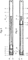
- Die Erfindung wird nachfolgend anhand eines Ausführungsbeispiels mit Bezug auf die beigefügten Zeichnungen näher erläutert. Es zeigen:
- Figur 1
- eine perspektivische Ansicht einer erfindungsgemäßen Vorrichtung zum Vorschub von Waren;
- Figur 2
- eine Seitenansicht der Vorrichtung der
Figur 1 ; - Figur 3
- eine Draufsicht auf die Vorrichtung der
Figur 2 ; - Figur 4
- eine Draufsicht auf die Vorrichtung der
Figur 2 mit dem Schieber in einer gefüllten Position, und - Figur 5
- eine perspektivische Explosionsdarstellung der Vorrichtung der
Figur 1 . - Eine Vorrichtung 1 zum Vorschub von Waren umfasst ein Führungsprofil 2, an dem eine oder mehrere Stege 3 zur Führung eines Schiebers 4 ausgebildet sind. An dem Schieber 4 sind zwei Führungsleisten 6 ausgebildet, die jeweils in ein Steg 3 an dem Führungsprofil 2 eingreifen. Es können aber auch andere Geometrien zur Führung des Schiebers 4 an dem Führungsprofil 2 vorgesehen werden. Der Schieber 4 umfasst eine plattenförmige Kontaktfläche 5, die zum Vorschub von Waren dient.
- An dem Führungsprofil 2 ist an einer Vorderseite ein Frontanker 7 fixiert, an dem ein Anschlag 8 ausgebildet ist, der die Bewegung der jeweils vordersten Ware zur Vorderseite hin begrenzt. Vor diesem Anschlag 8 befindet sich an einer Vorderseite ein Sichtfenster 9 aus einem zumindest teilweise transparenten oder transluzenten Material, das eine Füllstandskontrolle ermöglicht.
- An dem Führungsprofil 2 ist zwischen den beiden Stegen 3 eine Kurvenführung 10 angeordnet, die leistenförmig ausgebildet ist und eine kürzere Länge als das Führungsprofil 2 besitzt. Die Kurvenführung 10 umfasst eine nutförmige Führungsbahn 16, die auf dem zum Frontanker 7 gegenüberliegenden Ende einen Einfahrbereich 17 aufweist, der sich trichterförmig erweitert.
- Wie aus der
Figur 2 ersichtlich ist, befindet sich in einem Gehäuse des Schiebers 4 eine Feder 12, die als Bandfeder ausgebildet ist und mit einem Ende 13 an einem Halter 14 des Frontankers 7 fixiert ist. Die Feder 12 spannt den Schieber 4 in eine Vorschubrichtung 15 zu dem Frontanker 7 vor, wie dies durch den Pfeil symbolisiert ist. - An dem Schieber 4 befindet sich auf der zu dem Führungsprofil 2 gewandten Seite ein Mitnehmer 11 in Form eines Vorsprunges, der in die nutförmige Führungsbahn 16 an der Kurvenführung 10 eingreift. Über den Mitnehmer 11 kann die Kurvenführung 10 relativ zu dem Führungsprofil 3 bewegt werden, um ein Markierungselement 18, das an dem Sichtfenster 9 angeordnet ist, zu verstellen. Alternativ kann der Vorsprung auch direkt am Schieber 4 angebracht sein.
- In
Figur 3 ist der Schieber 4 der Vorrichtung in einer Leerstandsposition gezeigt, in der der Schieber 4 benachbart zu dem Anschlag 8 angeordnet ist, so dass nur noch wenige Waren zwischen der Kontaktfläche 5 und dem Anschlag 8 vorgesehen sind. Um diesen Leerstand anzuzeigen, ist durch die Bewegung des Schiebers 4 entlang der Führungsbahn 16 das Markierungselement 18 zu einem transparenten Bereich 21 des Sichtfensters 9 verschoben worden. Das Sichtfenster 9 umfasst einen blickdichten Bereich 20 und einen transparenten Bereich 21. - In
Figur 4 ist der Schieber 4 in einer Position gezeigt, in der noch ausreichend Waren zwischen der Kontaktfläche 5 und dem Anschlag 8 vorgesehen sind. Durch die Bewegung entlang der Führungsbahn 16 ist das Markierungselement 18 von dem transparenten Bereich 21 zu dem blickdichten Bereich 20 verschoben worden, so dass nun an dem Sichtfenster 9 das Markierungselement nicht oder nur wenig sichtbar ist. Durch eine Bewegung des Schiebers 4 zu dem Anschlag 8 wird das Markierungselement 18 an dem Sichtfenster 9 verstellt, wobei das Markierungselement 18 stufenlos von dem blickdichten Bereich 20 zu dem transparenten Bereich 21 verschoben werden kann. Dadurch kann visuell der Füllstand vor dem Schieber 4 an dem Sichtfenster 9 angezeigt werden. Statt dem transparenten Bereich 21 kann auch eine Öffnung vorgesehen sein, durch die das Markierungselement 18 sichtbar ist. - Das Sichtfenster 9 befindet sich dabei vor dem plattenförmigen Anschlag 8 in Draufsicht, so dass das Sichtfenster 9 auch von oben und nicht nur von vorne sichtbar ist. Das Sichtfenster 9 ist dabei gewölbt ausgebildet, beispielsweise über einen Winkelbereich von rund 90°, so dass das Markierungselement 18 innerhalb des Sichtfensters 9 über einen Winkelbereich von mindestens 90°, vorzugsweise mindestens 120°, sichtbar ist. Dadurch kann der Füllstand auch bei einer Betrachtung von oben auf das Sichtfenster 9 ermittelt werden.
- In
Figur 5 ist die Vorrichtung 1 zum Vorschub von Waren in einer Explosionsdarstellung gezeigt. Es ist erkennbar, dass die leistenförmige Kurvenführung 10 ein Markierungselement 18 aufweist, das in Längsrichtung am Führungsprofil 2 fixiert ist. Beispielsweise kann das Markierungselement 18 eine nach unten offene Aufnahme aufweisen, die entlang einer Leiste an dem Frontanker 7 geführt ist, so dass das Markierungselement 18 im Wesentlichen senkrecht zu der Längsrichtung des Führungsprofils 2 beweglich ist, aber in Längsrichtung des Führungsprofils 2 unbeweglich an dem Frontanker 7 angeordnet ist. - In dem dargestellten Ausführungsbeispiel ist die Kurvenführung 10 einstückig ausgebildet. Es ist natürlich möglich, das Markierungselement 18 und die Kurvenführung 10 aus mehreren Teilen zusammenzusetzen. Zudem kann das Markierungselement 18 auch anders ausgebildet sein, beispielsweise kann eine Bewegung des Markierungselementes 18 bei einem Verfahren des Schiebers 4 auch in eine andere Richtung als senkrecht zur Längsrichtung des Führungsprofils 2 verlaufen.
- In einer weiteren Ausgestaltung kann das Sichtfenster 9 auch durchgängig transparent ausgebildet sein oder einen Filter aufweisen, damit das Markierungselement 18 in einem ersten Bereich eine andere Farbe aufweist als in einem zweiten Bereich. Das Markierungselement 18 kann zudem Symbole aufweisen, um den genauen Füllstand zahlenmäßig anzuzeigen.
-
- 1
- Vorrichtung
- 2
- Führungsprofil
- 3
- Steg
- 4
- Schieber
- 5
- Kontaktfläche
- 6
- Führungsleiste
- 7
- Frontanker
- 8
- Anschlag
- 9
- Sichtfenster
- 10
- Kurvenführung
- 11
- Mitnehmer
- 12
- Feder
- 13
- Ende
- 14
- Halter
- 15
- Vorschubrichtung
- 16
- Führungsbahn
- 17
- Einfahrbereich
- 18
- Markierungselement
- 20
- blickdichter Bereich
- 21
- transparenter Bereich
Claims (12)
- Vorrichtung (1) zum Vorschub von Waren, mit einem entlang eines Führungsprofils (2) verfahrbaren Schieber (4), der durch eine Feder (12) in eine Vorschubrichtung vorgespannt ist, um Waren zu einem Anschlag (8) an einem Frontanker (7) zu bewegen, wobei ein Markierungselement (18) an dem Frontanker (7) zur Anzeige des Füllstandes vorgesehen ist, dadurch gekennzeichnet, dass ein Mitnehmer (11) zusammen mit dem Schieber (4) bewegbar und entlang einer Kurvenführung (10) verfahrbar ist, wobei das Markierungselement (18) durch die Kurvenführung (10) verstellbar ist.
- Vorrichtung nach Anspruch 1, dadurch gekennzeichnet, dass die Kurvenführung (10) zumindest teilweise geneigt zur Bewegungsrichtung des Schiebers (4) ausgerichtet ist.
- Vorrichtung nach Anspruch 1 oder 2, dadurch gekennzeichnet, dass die Kurvenführung (10) leistenförmig ausgebildet ist und beweglich an dem Führungsprofil (3) angeordnet ist.
- Vorrichtung nach einem der vorhergehenden Ansprüche, dadurch gekennzeichnet, dass der Mitnehmer (11) einen Vorsprung umfasst, der an einer Unterseite des Schiebers (4) fixiert ist.
- Vorrichtung nach einem der vorhergehenden Ansprüche, dadurch gekennzeichnet, dass die Kurvenführung (10) in Bewegungsrichtung des Schiebers (4) fixiert ist.
- Vorrichtung nach Anspruch 5, dadurch gekennzeichnet, dass die Kurvenführung (10) über einen Halteabschnitt an dem Markierungselement (18) an dem Frontanker (7) in Bewegungsrichtung des Schiebers (4) gehalten ist und senkrecht zur Bewegungsrichtung beweglich angeordnet ist.
- Vorrichtung nach einem der vorhergehenden Ansprüche, dadurch gekennzeichnet, dass das Sichtfenster (9) einen transparenten Bereich (21) aufweist, in dem das Markierungselement (18) sichtbar und verstellbar angeordnet ist.
- Vorrichtung nach einem der vorhergehenden Ansprüche, dadurch gekennzeichnet, dass sich die Kurvenführung (10) im Wesentlichen über die gesamte Länge des Verfahrbereiches des Schiebers (4) erstreckt.
- Vorrichtung nach einem der Ansprüche 1 bis 7, dadurch gekennzeichnet, dass die Kurvenführung (10) einen Einfahrbereich (17) aufweist, an dem der Mitnehmer (11) in die Führungsbahn (16) der Kurvenführung (10) ein- und ausfahrbar ist.
- Vorrichtung nach einem der vorhergehenden Ansprüche oder nach dem Oberbegriff des Anspruches 1, dadurch gekennzeichnet, dass an dem Frontanker (7) ein von dem Anschlag (8) zu einer Vorderseite hervorstehendes Sichtfenster (7) und/oder eine Öffnung vorgesehen ist, an dem oder der ein Abschnitt des Markierungselementes (10) einsehbar ist.
- Vorrichtung nach Anspruch 10, dadurch gekennzeichnet, dass das Sichtfenster (9) zumindest teilweise gewölbt ist und eine Aufnahme für einen Teil des Markierungselementes (18) ausbildet.
- Vorrichtung nach Anspruch 10 oder 11, dadurch gekennzeichnet, dass das Sichtfenster (9) oder die Öffnung einen Einblick auf das Markierungselement (18) über einen Winkelbereich von mindestens 90° ermöglichen.
Priority Applications (1)
| Application Number | Priority Date | Filing Date | Title |
|---|---|---|---|
| PL20160940T PL3741264T3 (pl) | 2019-05-22 | 2020-03-04 | Urządzenie do przesuwania towarów |
Applications Claiming Priority (1)
| Application Number | Priority Date | Filing Date | Title |
|---|---|---|---|
| DE202019102900.5U DE202019102900U1 (de) | 2019-05-22 | 2019-05-22 | Vorrichtung zum Vorschub von Waren |
Publications (2)
| Publication Number | Publication Date |
|---|---|
| EP3741264A1 true EP3741264A1 (de) | 2020-11-25 |
| EP3741264B1 EP3741264B1 (de) | 2022-02-23 |
Family
ID=69770628
Family Applications (1)
| Application Number | Title | Priority Date | Filing Date |
|---|---|---|---|
| EP20160940.1A Active EP3741264B1 (de) | 2019-05-22 | 2020-03-04 | Vorrichtung zum vorschub von waren |
Country Status (4)
| Country | Link |
|---|---|
| EP (1) | EP3741264B1 (de) |
| DE (1) | DE202019102900U1 (de) |
| ES (1) | ES2914426T3 (de) |
| PL (1) | PL3741264T3 (de) |
Families Citing this family (1)
| Publication number | Priority date | Publication date | Assignee | Title |
|---|---|---|---|---|
| US12171345B2 (en) | 2022-04-22 | 2024-12-24 | Fasteners For Retail, Inc. | Product pusher with manual actuator |
Citations (2)
| Publication number | Priority date | Publication date | Assignee | Title |
|---|---|---|---|---|
| US20140008382A1 (en) * | 2012-07-09 | 2014-01-09 | Checkpoint Systems, Inc. | Item pusher apparatus with channel-based shuttle displacement detection and associated methods |
| DE102013104023A1 (de) | 2013-04-22 | 2014-10-23 | POS TUNING Udo Voßhenrich GmbH & Co. KG | Vorrichtung zum Vorschub von Waren |
-
2019
- 2019-05-22 DE DE202019102900.5U patent/DE202019102900U1/de not_active Expired - Lifetime
-
2020
- 2020-03-04 EP EP20160940.1A patent/EP3741264B1/de active Active
- 2020-03-04 ES ES20160940T patent/ES2914426T3/es active Active
- 2020-03-04 PL PL20160940T patent/PL3741264T3/pl unknown
Patent Citations (2)
| Publication number | Priority date | Publication date | Assignee | Title |
|---|---|---|---|---|
| US20140008382A1 (en) * | 2012-07-09 | 2014-01-09 | Checkpoint Systems, Inc. | Item pusher apparatus with channel-based shuttle displacement detection and associated methods |
| DE102013104023A1 (de) | 2013-04-22 | 2014-10-23 | POS TUNING Udo Voßhenrich GmbH & Co. KG | Vorrichtung zum Vorschub von Waren |
Also Published As
| Publication number | Publication date |
|---|---|
| PL3741264T3 (pl) | 2022-06-27 |
| EP3741264B1 (de) | 2022-02-23 |
| ES2914426T3 (es) | 2022-06-10 |
| DE202019102900U1 (de) | 2020-08-25 |
Similar Documents
| Publication | Publication Date | Title |
|---|---|---|
| DE3321733A1 (de) | Kettenwirkmaschine mit jacquard-lochnadeln | |
| DE2814318C2 (de) | Einstellbarer Verschluß, insbesondere für Kleidungsstücke | |
| EP3741264B1 (de) | Vorrichtung zum vorschub von waren | |
| DE3618973A1 (de) | Hoeheneinstellbare vorrichtung an einem sicherheitsgurt fuer kraftfahrzeuge | |
| DE2447090A1 (de) | Fallsicherungsvorrichtung | |
| EP1967074A1 (de) | Schließwerkzeugbaugruppe | |
| DE102012106865B4 (de) | Fixiervorrichtung für einen Ausstattungsgegenstand an einer Fixierschiene | |
| DE1584071B1 (de) | Feststeller fuer Tueren | |
| DE2004931A1 (de) | Vorrichtung zum Zuführen von Stabstahl | |
| DE1905569A1 (de) | Filterwechselmechanismus fuer optische Geraete | |
| EP0703114B1 (de) | Schubladenascher für Fahrzeuge | |
| EP3865013A1 (de) | Vorrichtung zum vorschub von waren | |
| DE3236035C1 (de) | Vorrichtung zur Herstellung einer Gewebe-Schnittleiste | |
| AT527682B1 (de) | Haltevorrichtung | |
| DE1940287A1 (de) | Automatische Abfuell- und Verschliessmaschine | |
| DE202004015416U1 (de) | Bodenführung für ein seitlich verschiebbares Trennelement | |
| DE3028190C2 (de) | Stanz-Biegeautomat zur Herstellung von Stanz-Biegeteilen aus band- oder drahtförmigem Material | |
| DE69308142T2 (de) | Lastenträger | |
| DE1242506B (de) | Gabellasche fuer Kettenfoerderer, insbesondere fuer Trogkettenfoerderer | |
| DE2219178A1 (de) | Schriftgutlocher | |
| DE2257681A1 (de) | Schloss mit zweigeteilter nuss | |
| DE102007008220A1 (de) | Transporteinrichtung zum Transport von Werkstückträgern | |
| DE3727482A1 (de) | Haarschneidemaschine | |
| DE1911596C (de) | Transportbehälter fur Forderanlagen mit Hochkantfbrderkanalen | |
| DE102599C (de) |
Legal Events
| Date | Code | Title | Description |
|---|---|---|---|
| PUAI | Public reference made under article 153(3) epc to a published international application that has entered the european phase |
Free format text: ORIGINAL CODE: 0009012 |
|
| STAA | Information on the status of an ep patent application or granted ep patent |
Free format text: STATUS: THE APPLICATION HAS BEEN PUBLISHED |
|
| AK | Designated contracting states |
Kind code of ref document: A1 Designated state(s): AL AT BE BG CH CY CZ DE DK EE ES FI FR GB GR HR HU IE IS IT LI LT LU LV MC MK MT NL NO PL PT RO RS SE SI SK SM TR |
|
| AX | Request for extension of the european patent |
Extension state: BA ME |
|
| STAA | Information on the status of an ep patent application or granted ep patent |
Free format text: STATUS: REQUEST FOR EXAMINATION WAS MADE |
|
| 17P | Request for examination filed |
Effective date: 20210326 |
|
| RBV | Designated contracting states (corrected) |
Designated state(s): AL AT BE BG CH CY CZ DE DK EE ES FI FR GB GR HR HU IE IS IT LI LT LU LV MC MK MT NL NO PL PT RO RS SE SI SK SM TR |
|
| GRAP | Despatch of communication of intention to grant a patent |
Free format text: ORIGINAL CODE: EPIDOSNIGR1 |
|
| STAA | Information on the status of an ep patent application or granted ep patent |
Free format text: STATUS: GRANT OF PATENT IS INTENDED |
|
| INTG | Intention to grant announced |
Effective date: 20210927 |
|
| GRAS | Grant fee paid |
Free format text: ORIGINAL CODE: EPIDOSNIGR3 |
|
| GRAA | (expected) grant |
Free format text: ORIGINAL CODE: 0009210 |
|
| STAA | Information on the status of an ep patent application or granted ep patent |
Free format text: STATUS: THE PATENT HAS BEEN GRANTED |
|
| AK | Designated contracting states |
Kind code of ref document: B1 Designated state(s): AL AT BE BG CH CY CZ DE DK EE ES FI FR GB GR HR HU IE IS IT LI LT LU LV MC MK MT NL NO PL PT RO RS SE SI SK SM TR |
|
| REG | Reference to a national code |
Ref country code: GB Ref legal event code: FG4D Free format text: NOT ENGLISH |
|
| REG | Reference to a national code |
Ref country code: CH Ref legal event code: EP |
|
| REG | Reference to a national code |
Ref country code: DE Ref legal event code: R096 Ref document number: 502020000663 Country of ref document: DE |
|
| REG | Reference to a national code |
Ref country code: AT Ref legal event code: REF Ref document number: 1469790 Country of ref document: AT Kind code of ref document: T Effective date: 20220315 |
|
| REG | Reference to a national code |
Ref country code: IE Ref legal event code: FG4D Free format text: LANGUAGE OF EP DOCUMENT: GERMAN |
|
| REG | Reference to a national code |
Ref country code: LT Ref legal event code: MG9D Ref country code: ES Ref legal event code: FG2A Ref document number: 2914426 Country of ref document: ES Kind code of ref document: T3 Effective date: 20220610 |
|
| REG | Reference to a national code |
Ref country code: SE Ref legal event code: TRGR |
|
| REG | Reference to a national code |
Ref country code: NL Ref legal event code: MP Effective date: 20220223 |
|
| PG25 | Lapsed in a contracting state [announced via postgrant information from national office to epo] |
Ref country code: RS Free format text: LAPSE BECAUSE OF FAILURE TO SUBMIT A TRANSLATION OF THE DESCRIPTION OR TO PAY THE FEE WITHIN THE PRESCRIBED TIME-LIMIT Effective date: 20220223 Ref country code: PT Free format text: LAPSE BECAUSE OF FAILURE TO SUBMIT A TRANSLATION OF THE DESCRIPTION OR TO PAY THE FEE WITHIN THE PRESCRIBED TIME-LIMIT Effective date: 20220623 Ref country code: NO Free format text: LAPSE BECAUSE OF FAILURE TO SUBMIT A TRANSLATION OF THE DESCRIPTION OR TO PAY THE FEE WITHIN THE PRESCRIBED TIME-LIMIT Effective date: 20220523 Ref country code: NL Free format text: LAPSE BECAUSE OF FAILURE TO SUBMIT A TRANSLATION OF THE DESCRIPTION OR TO PAY THE FEE WITHIN THE PRESCRIBED TIME-LIMIT Effective date: 20220223 Ref country code: LT Free format text: LAPSE BECAUSE OF FAILURE TO SUBMIT A TRANSLATION OF THE DESCRIPTION OR TO PAY THE FEE WITHIN THE PRESCRIBED TIME-LIMIT Effective date: 20220223 Ref country code: HR Free format text: LAPSE BECAUSE OF FAILURE TO SUBMIT A TRANSLATION OF THE DESCRIPTION OR TO PAY THE FEE WITHIN THE PRESCRIBED TIME-LIMIT Effective date: 20220223 Ref country code: BG Free format text: LAPSE BECAUSE OF FAILURE TO SUBMIT A TRANSLATION OF THE DESCRIPTION OR TO PAY THE FEE WITHIN THE PRESCRIBED TIME-LIMIT Effective date: 20220523 |
|
| PG25 | Lapsed in a contracting state [announced via postgrant information from national office to epo] |
Ref country code: LV Free format text: LAPSE BECAUSE OF FAILURE TO SUBMIT A TRANSLATION OF THE DESCRIPTION OR TO PAY THE FEE WITHIN THE PRESCRIBED TIME-LIMIT Effective date: 20220223 Ref country code: GR Free format text: LAPSE BECAUSE OF FAILURE TO SUBMIT A TRANSLATION OF THE DESCRIPTION OR TO PAY THE FEE WITHIN THE PRESCRIBED TIME-LIMIT Effective date: 20220524 Ref country code: FI Free format text: LAPSE BECAUSE OF FAILURE TO SUBMIT A TRANSLATION OF THE DESCRIPTION OR TO PAY THE FEE WITHIN THE PRESCRIBED TIME-LIMIT Effective date: 20220223 |
|
| PG25 | Lapsed in a contracting state [announced via postgrant information from national office to epo] |
Ref country code: IS Free format text: LAPSE BECAUSE OF FAILURE TO SUBMIT A TRANSLATION OF THE DESCRIPTION OR TO PAY THE FEE WITHIN THE PRESCRIBED TIME-LIMIT Effective date: 20220623 |
|
| PG25 | Lapsed in a contracting state [announced via postgrant information from national office to epo] |
Ref country code: SM Free format text: LAPSE BECAUSE OF FAILURE TO SUBMIT A TRANSLATION OF THE DESCRIPTION OR TO PAY THE FEE WITHIN THE PRESCRIBED TIME-LIMIT Effective date: 20220223 Ref country code: SK Free format text: LAPSE BECAUSE OF FAILURE TO SUBMIT A TRANSLATION OF THE DESCRIPTION OR TO PAY THE FEE WITHIN THE PRESCRIBED TIME-LIMIT Effective date: 20220223 Ref country code: RO Free format text: LAPSE BECAUSE OF FAILURE TO SUBMIT A TRANSLATION OF THE DESCRIPTION OR TO PAY THE FEE WITHIN THE PRESCRIBED TIME-LIMIT Effective date: 20220223 Ref country code: EE Free format text: LAPSE BECAUSE OF FAILURE TO SUBMIT A TRANSLATION OF THE DESCRIPTION OR TO PAY THE FEE WITHIN THE PRESCRIBED TIME-LIMIT Effective date: 20220223 Ref country code: DK Free format text: LAPSE BECAUSE OF FAILURE TO SUBMIT A TRANSLATION OF THE DESCRIPTION OR TO PAY THE FEE WITHIN THE PRESCRIBED TIME-LIMIT Effective date: 20220223 |
|
| REG | Reference to a national code |
Ref country code: DE Ref legal event code: R097 Ref document number: 502020000663 Country of ref document: DE |
|
| PG25 | Lapsed in a contracting state [announced via postgrant information from national office to epo] |
Ref country code: MC Free format text: LAPSE BECAUSE OF FAILURE TO SUBMIT A TRANSLATION OF THE DESCRIPTION OR TO PAY THE FEE WITHIN THE PRESCRIBED TIME-LIMIT Effective date: 20220223 Ref country code: AL Free format text: LAPSE BECAUSE OF FAILURE TO SUBMIT A TRANSLATION OF THE DESCRIPTION OR TO PAY THE FEE WITHIN THE PRESCRIBED TIME-LIMIT Effective date: 20220223 |
|
| REG | Reference to a national code |
Ref country code: BE Ref legal event code: MM Effective date: 20220331 |
|
| PLBE | No opposition filed within time limit |
Free format text: ORIGINAL CODE: 0009261 |
|
| STAA | Information on the status of an ep patent application or granted ep patent |
Free format text: STATUS: NO OPPOSITION FILED WITHIN TIME LIMIT |
|
| REG | Reference to a national code |
Ref country code: DE Ref legal event code: R081 Ref document number: 502020000663 Country of ref document: DE Owner name: POS TUNING GMBH, DE Free format text: FORMER OWNER: POS TUNING UDO VOSSHENRICH GMBH & CO. KG, 32107 BAD SALZUFLEN, DE |
|
| PG25 | Lapsed in a contracting state [announced via postgrant information from national office to epo] |
Ref country code: LU Free format text: LAPSE BECAUSE OF NON-PAYMENT OF DUE FEES Effective date: 20220304 Ref country code: IE Free format text: LAPSE BECAUSE OF NON-PAYMENT OF DUE FEES Effective date: 20220304 |
|
| 26N | No opposition filed |
Effective date: 20221124 |
|
| PG25 | Lapsed in a contracting state [announced via postgrant information from national office to epo] |
Ref country code: SI Free format text: LAPSE BECAUSE OF FAILURE TO SUBMIT A TRANSLATION OF THE DESCRIPTION OR TO PAY THE FEE WITHIN THE PRESCRIBED TIME-LIMIT Effective date: 20220223 Ref country code: BE Free format text: LAPSE BECAUSE OF NON-PAYMENT OF DUE FEES Effective date: 20220331 |
|
| REG | Reference to a national code |
Ref country code: CH Ref legal event code: PL |
|
| PG25 | Lapsed in a contracting state [announced via postgrant information from national office to epo] |
Ref country code: LI Free format text: LAPSE BECAUSE OF NON-PAYMENT OF DUE FEES Effective date: 20230331 Ref country code: CH Free format text: LAPSE BECAUSE OF NON-PAYMENT OF DUE FEES Effective date: 20230331 |
|
| PG25 | Lapsed in a contracting state [announced via postgrant information from national office to epo] |
Ref country code: MK Free format text: LAPSE BECAUSE OF FAILURE TO SUBMIT A TRANSLATION OF THE DESCRIPTION OR TO PAY THE FEE WITHIN THE PRESCRIBED TIME-LIMIT Effective date: 20220223 Ref country code: CY Free format text: LAPSE BECAUSE OF FAILURE TO SUBMIT A TRANSLATION OF THE DESCRIPTION OR TO PAY THE FEE WITHIN THE PRESCRIBED TIME-LIMIT Effective date: 20220223 |
|
| PG25 | Lapsed in a contracting state [announced via postgrant information from national office to epo] |
Ref country code: HU Free format text: LAPSE BECAUSE OF FAILURE TO SUBMIT A TRANSLATION OF THE DESCRIPTION OR TO PAY THE FEE WITHIN THE PRESCRIBED TIME-LIMIT; INVALID AB INITIO Effective date: 20200304 |
|
| PG25 | Lapsed in a contracting state [announced via postgrant information from national office to epo] |
Ref country code: TR Free format text: LAPSE BECAUSE OF FAILURE TO SUBMIT A TRANSLATION OF THE DESCRIPTION OR TO PAY THE FEE WITHIN THE PRESCRIBED TIME-LIMIT Effective date: 20220223 |
|
| PG25 | Lapsed in a contracting state [announced via postgrant information from national office to epo] |
Ref country code: MT Free format text: LAPSE BECAUSE OF FAILURE TO SUBMIT A TRANSLATION OF THE DESCRIPTION OR TO PAY THE FEE WITHIN THE PRESCRIBED TIME-LIMIT Effective date: 20220223 |
|
| PGFP | Annual fee paid to national office [announced via postgrant information from national office to epo] |
Ref country code: AT Payment date: 20250417 Year of fee payment: 5 |
|
| PGFP | Annual fee paid to national office [announced via postgrant information from national office to epo] |
Ref country code: ES Payment date: 20250416 Year of fee payment: 6 |
|
| PGFP | Annual fee paid to national office [announced via postgrant information from national office to epo] |
Ref country code: IT Payment date: 20250331 Year of fee payment: 6 |
|
| PGFP | Annual fee paid to national office [announced via postgrant information from national office to epo] |
Ref country code: SE Payment date: 20260309 Year of fee payment: 7 |
|
| PGFP | Annual fee paid to national office [announced via postgrant information from national office to epo] |
Ref country code: GB Payment date: 20260305 Year of fee payment: 7 |
|
| PGFP | Annual fee paid to national office [announced via postgrant information from national office to epo] |
Ref country code: DE Payment date: 20260116 Year of fee payment: 7 |
|
| PGFP | Annual fee paid to national office [announced via postgrant information from national office to epo] |
Ref country code: FR Payment date: 20260305 Year of fee payment: 7 |
|
| PGFP | Annual fee paid to national office [announced via postgrant information from national office to epo] |
Ref country code: CZ Payment date: 20260211 Year of fee payment: 7 |
|
| PGFP | Annual fee paid to national office [announced via postgrant information from national office to epo] |
Ref country code: PL Payment date: 20260108 Year of fee payment: 7 |