EP3741920A1 - Drain de rénovation pour réparation de drain en béton - Google Patents
Drain de rénovation pour réparation de drain en béton Download PDFInfo
- Publication number
- EP3741920A1 EP3741920A1 EP20020242.2A EP20020242A EP3741920A1 EP 3741920 A1 EP3741920 A1 EP 3741920A1 EP 20020242 A EP20020242 A EP 20020242A EP 3741920 A1 EP3741920 A1 EP 3741920A1
- Authority
- EP
- European Patent Office
- Prior art keywords
- drain
- renovation
- liner
- concrete
- renovation drain
- Prior art date
- Legal status (The legal status is an assumption and is not a legal conclusion. Google has not performed a legal analysis and makes no representation as to the accuracy of the status listed.)
- Pending
Links
Images


Classifications
-
- E—FIXED CONSTRUCTIONS
- E03—WATER SUPPLY; SEWERAGE
- E03F—SEWERS; CESSPOOLS
- E03F5/00—Sewerage structures
- E03F5/02—Manhole shafts or other inspection chambers; Snow-filling openings; accessories
-
- E—FIXED CONSTRUCTIONS
- E02—HYDRAULIC ENGINEERING; FOUNDATIONS; SOIL SHIFTING
- E02D—FOUNDATIONS; EXCAVATIONS; EMBANKMENTS; UNDERGROUND OR UNDERWATER STRUCTURES
- E02D29/00—Independent underground or underwater structures; Retaining walls
- E02D29/12—Manhole shafts; Other inspection or access chambers; Accessories therefor
- E02D29/128—Repairs of manhole shafts
-
- E—FIXED CONSTRUCTIONS
- E03—WATER SUPPLY; SEWERAGE
- E03F—SEWERS; CESSPOOLS
- E03F3/00—Sewer pipe-line systems
- E03F3/04—Pipes or fittings specially adapted to sewers
-
- E—FIXED CONSTRUCTIONS
- E03—WATER SUPPLY; SEWERAGE
- E03F—SEWERS; CESSPOOLS
- E03F3/00—Sewer pipe-line systems
- E03F3/06—Methods of, or installations for, laying sewer pipes
-
- E—FIXED CONSTRUCTIONS
- E03—WATER SUPPLY; SEWERAGE
- E03F—SEWERS; CESSPOOLS
- E03F5/00—Sewerage structures
- E03F5/02—Manhole shafts or other inspection chambers; Snow-filling openings; accessories
- E03F5/021—Connection of sewer pipes to manhole shaft
-
- E—FIXED CONSTRUCTIONS
- E03—WATER SUPPLY; SEWERAGE
- E03F—SEWERS; CESSPOOLS
- E03F5/00—Sewerage structures
- E03F5/04—Gullies inlets, road sinks, floor drains with or without odour seals or sediment traps
- E03F5/0401—Gullies for use in roads or pavements
-
- E—FIXED CONSTRUCTIONS
- E03—WATER SUPPLY; SEWERAGE
- E03F—SEWERS; CESSPOOLS
- E03F5/00—Sewerage structures
- E03F5/04—Gullies inlets, road sinks, floor drains with or without odour seals or sediment traps
- E03F5/0401—Gullies for use in roads or pavements
- E03F5/0403—Gullies for use in roads or pavements with a sediment trap
-
- F—MECHANICAL ENGINEERING; LIGHTING; HEATING; WEAPONS; BLASTING
- F16—ENGINEERING ELEMENTS AND UNITS; GENERAL MEASURES FOR PRODUCING AND MAINTAINING EFFECTIVE FUNCTIONING OF MACHINES OR INSTALLATIONS; THERMAL INSULATION IN GENERAL
- F16L—PIPES; JOINTS OR FITTINGS FOR PIPES; SUPPORTS FOR PIPES, CABLES OR PROTECTIVE TUBING; MEANS FOR THERMAL INSULATION IN GENERAL
- F16L55/00—Devices or appurtenances for use in, or in connection with, pipes or pipe systems
- F16L55/16—Devices for covering leaks in pipes or hoses, e.g. hose-menders
- F16L55/179—Devices for covering leaks in pipes or hoses, e.g. hose-menders specially adapted for bends, branch units, branching pipes or the like
Definitions
- an invention relates to repairing storm drains, yard drains, inspection chambers, or other drains made of concrete; the invention further relates to liner members and renovation drains to be used in pipeline renovations.
- a storm drain (or storm sewer) is used for collecting rain water or storm water.
- the storm drain is situated such that rain water or storm water flows into the storm drain.
- the water rained on a roof can be led to gutters and via the tubing coupled to the gutters into a yard drain. From the yard drain the water is led, for example, into a municipal storm drainage system.
- rain water and sewer water are led in the same piping system and a yard drain coupled to the piping system possibly receives storm water as well as sewer water.
- storm water and sewer water On new residential areas, storm water and sewer water have separated piping systems, and in that case, the yard drain receives either storm water or sewer water.
- the drain to be repaired is expected to compose mostly of concrete and thus it is termed a "concrete drain".
- the concrete drain has on its bottom one or more chutes made of concrete and each of the chutes is coupled to an inlet pipe of the concrete drain, or an outlet pipe of the concrete drain.
- the concrete drain can be repaired by cleaning its inner surface and re-covering the inner surface with a concrete layer. This re-covering of the inner surface, however, includes a lot of manual work, which makes the method expensive.
- Epoxy spaying is another known renovation method but the epoxy spraying suits poorly for the concrete drain renovation because epoxy does not properly stick to wet concrete, and drying of a concrete drain takes a lot of time.
- a renovation drain is a third known renovation method for a concrete drain.
- the renovation drain is made of plastic and its diameter is less than the diameter of the concrete drain to enable its assembly inside the concrete drain.
- holes are made on the sides of the renovation drain in order to fit parts.
- the renovation drain can be attached to the concrete drain with a portion of mass concrete or gravel.
- Lining is a fourth known method for a concrete drain.
- a liner to be used in the method includes porous material, such as felt, and restorative material, such as PVC (polyvinyl chloride).
- the liner is impregnated with an impregnating compound including epoxy or some other type of resin. After hardening of the compound, the liner forms a durable lining inside the concrete drain.
- a liner member includes a liner comprising multiple branches.
- the liner member intended for a Y branch comprises three branches.
- a packer and a liner member are moved, for example, by a ramrod to the Y branch, one of the liner branches is forced out of the packer by compressed air and simultaneously the compressed air pressures each liner branch against the inner walls of the Y branch.
- a preliner is a tool to be used in lining.
- One purpose of the preliner is to operate as a mold against which a liner gets squeezed. This kind of mold is needed, for example, when corrosion has created holes to the cast iron pipe to be repaired.
- a problem of the prior art relates to the situation in which the pipes connecting concrete drains are to be repaired using pipe lining and at least one of the drains is to be repaired placing a renovation drain inside of it, or alternatively, assembling a cleaning cap.
- An ordinary liner member is not suitable in this situation.
- JP2002295785 can be considered to represent the closest prior art because it describes a liner member including two different manufacturing materials.
- the first material is rubber and the second material is a liner to be impregnated with compound such that the liner is adhered to a branch which is made of rubber.
- the branch includes a collar to which the liner is adhered.
- JP2007321840 describes a liner member made of rubber only.
- JP2002301766 describes a liner member that includes two different types of plastic. US2011203719 , US2009194184 , and WO2008039767 describe liner members made of liner only.
- Another problem of the prior art is related to manual work stages and the work hours needed for assembling liner members.
- the third problem of the prior art is related to a fact that concrete drains differ from each other, due to which various liner members are needed for repairing them.
- a liner member can be manufactured, for example, by molding plastic but it is very uneconomic to make a cast for each different liner member.
- An aspect of the innovation is to solve the above-mentioned problems in repairing of concrete drains.
- the chutes on the concrete drain bottom may be located on the same line but it's also possible that an angle between them is less than 180 degrees.
- a Y branch should fit properly into the concrete drain chutes, but it's possible that no appropriate (plastic made) Y branch is available
- An aspect of the invention is to use lining and a Y branch when renovating a concrete drain and pipes coupled with the renovation drain.
- the appropriate Y branch can be ordered from a sewing company by announcing them the number of inlet and outlet pipes and the angles between the pipes.
- the invention applies to various concrete drains, also concrete drains without chutes.
- An aspect of the invention is to utilize a renovation drain which includes a Y branch and which is attachable to a piping connection of a building, a solid cover slab, a grate cover slab, or telescope pipe such that the telescope pipe is moveable in vertical direction in relation to the renovation drain bottom.
- a renovation drain is a piece which retains its shape and which is attachable in a watertight manner to a Y branch. Then pipes (made of plastic), or other pieces retaining their shape, can be attached to the renovation drain.
- the innovation concerns a renovation drain for repairing a concrete drain that comprises a bottom, an inlet at the bottom, and an edge extending around the renovation drain.
- the renovation drain further comprises a liner member and the liner member includes a liner for lining such that a first branch in the liner is intended to be assembled towards an inlet pipe of the concrete drain, a second branch in the liner is intended to be assembled towards an outlet pipe of the concrete drain, and the liner member becomes attached to the renovation drain around the inlet.
- FIGURE 1 shows a renovation drain 100 assembled into a concrete drain (the concrete drain and its inlet pipe and outlet pipe are not shown).
- renovation drain 100 intended for repairing a concrete drain comprises a bottom 101, an inlet 102 at bottom 101, and an edge 103.
- Construction drain 100 further includes a liner member 104.
- Liner member 104 comprises a liner to be impregnated with compound such that a first branch 105 extends towards the inlet pipe of the concrete drain and a second branch 106 extends towards the outlet pipe of the concrete drain.
- liner member 104 comprises a third branch 107 by which third branch 107 attaches with compound to renovation drain 100 around its inlet 102.
- renovation drain 100 comprises a bushing 108 for attaching liner member 104.
- third branch 107 of liner member 104 is attached with a clamp ring 109 against the outer surface of bushing 108.
- first branch 105, second branch 106, and third branch 107 are solid and remain their shape.
- renovation drain 100 includes in this example a funnel-shaped piece.
- the production material of the piece is e.g. plastic such as PVC (polyvinyl chloride) or PE (polyethylene), or the production material is metal such as aluminum or stainless steel.
- Construction drain 100 in accordance with the invention comprises, for example, a funnel-shaped piece (made of plastic) and a liner member 104 attached to it.
- Liner member 104 can be subcontracted such that it will include as many branches as needed and the angles between the branches are appropriate for the concrete drain to be renovated.
- Liner member 104 is composed of liner pieces that are attached with stitches to each other.
- third branch 107 is attached with stitches 110 to first branch 105 and second branch 106.
- a liner hole 111 is formed between first branch 105 and second branch 106.
- Inlet 102 extends via bushing 108 and liner hole 111 into the liner.
- FIGURE 2A shows a cross-section of renovation drain 100 and concrete drain 20, wherein concrete drain 201 is marked with a thick line and its middle and upper part is replaced with three dots.
- concrete drain 201 operates as an inspection drain.
- Construction drain 100 for repairing concrete drain 201 is assembled in the figure but the mouth 202 of renovation drain 100 is not yet closed. Mouth 202 can be closed, for example, with a lid (not shown).
- renovation drain 100 comprises a board 203 which is attached to bottom 101 and which extends around bottom 101.
- the upper edge of board 203 operates as the upper edge of renovation drain 100.
- Board 203 can be utilized in pipe connections. If a so-called house connection, i.e. a pipe from a real estate, is led into concrete drain 201 to be renovated, a hole can be made to board 203 of renovation drain 100 and then connect renovation drain 100 with a pipe (or pipes attached together) through that hole to the house connection.
- Liner member 104 is assembled into concrete drain 201 such that first branch 105 of liner member 104 rests on the bottom of a first chute of concrete drain 201 and second branch 106 rests on the bottom of a second chute 205 of concrete drain 201.
- first branch 105 extends somewhat inside an inlet pipe 206 and second branch 106 extends somewhat inside an outlet pipe 207.
- Water is allowed to flow from inlet pipe 206 via liner member 104 into outlet pipe 207 when the liner included in liner member 104 is hardened. More than one inlet pipe and/or more than one outlet pipe may be coupled to concrete drain 201.
- FIGURE 2B shows in a first view 211 a first sealant option for liner member 104 and concrete drain 201, and a second sealant option in a second view 212, and a third sealant option in a third view 213.
- a sealant 214 is a rubber ring whose lower surface has a groove 215 that extends around the rubber ring.
- the diameter of sealant 214 at groove 215 is the same as the diameter of edge 103 in the renovation drain in Figure 2A .
- a sealant 216 is rubber ring that is tensed and thus it adheres to the groove formed onto the outer surface of telescope pipe 217.
- the diameter of telescope pipe 217 is slightly smaller than the diameter of board 203 in renovation drain 100, thus telescope pipe 217 and concrete drain 201 can be placed one inside another such that a sealant 216 makes their joint water-tight.
- sealant 218 is intended to be attached to the edge of the renovation drain shown in Figure 1 .
- the under surface of sealant 218 includes a groove 219 into which the edge of the renovation drain can be pushed.
- FIGURE 3A shows renovation drain 100 and its lid 301 placed on the bottom of concrete drain 201 wherein renovation drain 100 is viewed as a cross-section.
- the shape of renovation drain 100 is different than in Figure 1 , because the bottom of renovation drain is flat and bushing 108 is located (partly) inside the renovation drain.
- the inner surface of bushing 108 provides a bonding surface for the liner member. If the bottom of the renovation drain is 5 mm thick, the inner surface of the hole cut to it provides a 5 mm high bonding surface. Such bonding surface is large enough when epoxy is used compound.
- Another possible purpose for bushing 108 is that it forms a sediment chamber 302 onto the bottom of renovation drain 100.
- Lid 301 with a handle has been squeezed with a clamp ring 303 against board 203 of renovation drain 100.
- Assembly of renovation drain 100 is performed, for example, in the following manner.
- Filling paste 304, such as gravel or sand, is brought into concrete drain 201 such that concrete drain 201 is filled from its bottom up to the dot line.
- FIGURE 3B shows an intersection view of renovation drain 100 and its board 203 assembled on the bottom of concrete drain 201 wherein telescope pipe 217 is pushed inside renovation drain 100.
- Construction drain 100 and liner member 104 included in it can be assembled, as described in the above, by filling concrete drain 201 with filling paste 304 up to the point marked with a dot line 311. When the compound has hardened the assembly is continued by assembling telescope pipe 217.
- telescope pipe 217 includes a cover slab 313 that is firmly attached to pipe-type-of part 312.
- Cover slab 313 includes a detachable cover 314 that provides an access inside renovation drain 100.
- Pipe-type-of part 312 in telescope pipe 217 is in this example made of plastic and cover slab 313 and cover 314 are made of cast iron.
- Telescope pipe 217 rests on its cover slap 313 on the ground. Because Telescope pipe 217 can move vertically in relation to the ground, possible elevations changes in relation the bottom of renovation drain 100 does not cause damage to renovation drain 100.
- renovation drain 100 includes bushing 108 attached to bottom 101 such that inlet 102 extends through bushing 108.
- Third branch 107 attached to liner member 107 is attached with compound to bushing 108.
- Liner member 104 can be assembled by using a packer (not shown) that squeezes third branch 107 against the inner surface 315 of bushing 108.
- FIG. 3B shows an inspection drain. If concrete drain 201 to be renovated is a drain intended for rain water and sewer water, renovation drain 100 is such drain whose board 203 is made about 500 mm high for a building pipe connection and a solid cover 314 is replaced with a grate cover. In this embodiment the bottom of renovation drain 100 operates as sediment chamber 302 that collects sand and garbage from rain water.
- FIGURE 4A shows from a bird's perspective renovation drain 100 and a preliner intended for a (piece of) liner 402. Edge 103 of renovation drain 100 is marked with a dotted line.
- the liner is assembled from another concrete drain via inlet pipe 206 into concrete drain 201 and via outlet pipe 207 to the next concrete drain.
- preliner 401 Because the liner is placed into preliner 401, it does not expand in open space inside concrete drain 201 too much when the liner is pressurized with some tool usable in a known lining method. In other words, preliner 401 results in that the liner will harden forming a pipe of a certain size.
- first branch 105 and second branch 106 of liner member 104 are placed via the hole inside liner 402.
- first branch 105 extends towards inlet pipe 206 up to dot line 403 but inside the inlet pipe 206.
- second branch 106 extends towards outlet pipe 207 up to a dot line 404.
- Liner hole 111 in reparation drain 100 is located at the hole cut to liner 402.
- FIGURE 4B shows liner 411, preliner 412 surrounding liner 411, and bushing 108 of renovation drain 100.
- the branches of liner member 104 i.e. first branch 105, second branch, and third branch are composed of liner 411.
- liner 411 is pressurized against preliner 412. Before the pressurizing, liner 411 is impregnated with compound and attached with clamp ring 109 against the outer surface of bushing 108 in renovation drain 100.
- the ends of first branch 105 and second branch 106 are tied in order to close them.
- Pressurizing can be performed by feeding water through inlet 102 into liner 411.
- the compound attaches liner member 104 to the outer surface of bushing 108.
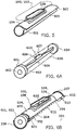
- FIGURE 5 shows with dashed lines renovation drain 100 and its edge 103.
- the renovation drain 100 can be assembled using an assembly tool which includes a by-pass flow pipe.
- the liner included in liner member 104 is horizontally split and the liner comprises a first lapel 501 and a second lapel 502 such that by placing first lapel 501 partly on second lapel 502 the liner forms a continuous pipe.
- the continuous pipe formed in this manner is hardened by compound in the assembly stage.
- Figure 5 shows an example of bushing 108 whose cross-section is not a circle but an oval.
- Bushing 108 is low in height and its diameter is large. The large diameter enables an easy removing of the assembly tool via bushing 108 out of liner member and it enhances maintainability of the sewer.
- renovation drain 100 comprises a plate type of attachment collar 503 with a curved form. Attachment collar 503 provides (quite broad) surface to which liner member 104 can be attached by compound.
- FIGURE 6A shows an assembly tool 601 for liner member 104 shown in Figure 5 .
- Assembly tool 601 comprises a by-pass flow pipe 602 and sealant rings such that a first sealant ring is attached to an end of by-pass flow pipe 602 and a second sealant ring is attached to the opposite end of by-pass flow pipe 602.
- the sealant rings can be pressurized.
- the water can be led through a hose located on the ground to another drain. This kind of arrangement, however, may be problematic, if there is vehicle traffic on the ground.
- assembly tool 601 comprises a coupler plate 605 and a bladder 606 (marked with dashed line). Bladder 606 is further adhered to a first sealant ring 603 and a second sealant ring 604.
- Coupler plate 605 is made of e.g. plastic and it is smaller than bushing 108 included in liner member 104. Therefore, coupler plate 605 and assembly tool 601 can be taken out of bushing 108.
- Two couplers are immersed into coupler plate 605 and one them, termed a "bladder coupler" 607, is intended for pressurizing bladder 606.
- a sealant ring coupler 608 is intended for pressurizing first sealant ring 603 and second sealant ring 604.
- Sealant ring coupler 608 comprises a Y branch from which hose 609 extends to first sealant ring 603 and another hose extends to second sealant ring 604.
- FIGURE 6B shows assembling liner member 104 onto the bottom of concrete drain 201. Some parts of renovation drain 100, such as its edge, is omitted from Figure 6B .
- First branch 105 rests on the bottom of a first chute 204 in concrete drain 201 and second branch 106 rests on the bottom of second chute 205 in concrete drain 201.
- the edges of first chute 204 and second chute 205 are marked with a dashed line 611.
- the assembly of liner member 104 comprises the following stages. First lapel 501 of the liner is longer than the other one and it is wrapped around assembly tool 601. Second lapel 502 is placed on first lapel 501. The ends of assembly tool 601 and the ends of liner member 104 are pushed into the pipes of concrete drain. In more detail, first sealant 603 is pushed into inlet pipe 206 and thus the end of first branch of liner member 104 is placed into inlet pipe 206.
- Second sealant ring (not shown) of assembly tool 601 is pushed into outlet pipe 207. Therefore, the end of second branch 106 is pushed into outlet pipe 207. Second branch 106 is attached with a half-pipe 612 to second chute 205. Finally, the edges of half-pipe 612 are attached (e.g. with a nail gun) to the bottom of concrete drain 201. In this example a nail 613 has penetrated the edge of half-pipe 612 and it has sunk into the concrete.
- First branch 105 is uncovered in figure 6A . After first branch 105 is covered with a half-pipe, liner member 104 is pressurized via bushing 108 by coupling fluid hoses to the couplers of coupler plate 605. For example, water or air can be used as pressurizing fluid.
- liner member 104 comprises half-pipe 612 intended for attaching liner member 104.
- half-pipe 612 and the liner form the same object.
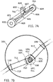
- FIGURE 7A shows an assembly tool 701 for the liner shown in figure 4B .
- the components of assembly tool 701 are operationally similar as the components of assembly tool 601 presented in the above.
- the components are by-pass flow pipe 602, first sealant ring 603, second sealant ring 604, coupler plate 605, bladder 606, bladder coupler 607, sealant ring coupler 608, and a hose 609 (for first sealant ring).
- bladder 606 in assembly tool 701 comprises a projection 702 for pressurizing the third branch.
- Coupler plate 605 is placed to the end of projection 702.
- FIGURE 7B shows from a bird's perspective another example of liner member 104 to be formed on an installation place.
- renovation drain 100 and its edge 103 are shown with dashed lines.
- Liner 411 included in liner member 104 is split and it includes lapels.
- the first lapel is wrapped around assembly tool 701 for assembling liner 411.
- assembly tool 701 remains inside the liner and the bladder included in assembly tool 701 can used for pressurizing the liner.
- half-pipe 612 and a second half-pipe 711 are covered with half-pipe 612 and a second half-pipe 711.
- Half-pipes are brought to the installation place to be shaped thereat.
- Half-pipe 612 and second half-pipe 711 are cut at the installation place with a foxtail saw.
- a piece having a shape of semicircle is cut from the end of half pipe 612 for third branch 107 of liner member 104.
- a piece having the shape of semicircle is cut from the end second half pipe 711 for third branch 107.
- Figure 7B shows a situation in which bushing 108, i.e. the third branch of the liner, extends out from the bottom of concrete drain 201 and a technician has placed bushing 108 around of it.
- Construction drain 100 is of the same kind as in Figure 1 .
- Coupler plate 605 attached to projection 702 is the only visible part of assembly tool 701.
- the both half-pipes are attached to the bottom of concrete drain 201, for example, with pieces of punched tape and nails.
- Punched tape is made of e.g. steel and it is generally used in construction work.
- Second half-pipe 711 is attached to the concrete drain with punched tape such that a piece of punched tape 712 passes over first half-pipe and it is attached from the both ends to the bottom of concrete drain 201 with nails of a nail gun.
- a corresponding piece of punched tape 713 is located at the opposite end of second half-pipe 711. It is possible to make a curve or an angle to liner member 104 by using half-pipes. The angles between the branches of liner member 104 should correspond to the angles of the chutes on the bottom of concrete drain 201.
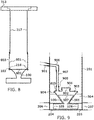
- FIGURE 8 shows a renovation drain system 800 for repairing a concrete drain.
- a detachable board 801 adheres to bottom 101 of renovation drain 100 and extends around it.
- Edge 103 of renovation drain 100 comprises sealant 218.
- a clamp ring 802 surrounds detachable board 801 and presses detachable board 801 against sealant 218, and makes the joint between detachable board 801 and renovation drain 100 water-tight.
- Telescope pipe 217 is attached to detachable board 801 and telescope pipe 217 rests on its cover slap 313 on the ground. Because telescope pipe 217 can move vertically in relation to detachable board 801, possible elevation changes in relation the bottom of renovation drain 100 does not cause damage to detachable board 801 or renovation drain 100.
- Detachable board 801 includes a house connection hole 803 for coupling renovation drain 100 to the pipe coming from the house.
- FIGURE 9 shows an example of renovation drain 100 having an inspection hole, wherein renovation drain 100 is illustrated with a dotted line.
- renovation drain 100 does not include board or a bushing but its bottom 101 has a funnel form and broadens upwards from the bottom of concrete drain 201.
- third branch 107 included in renovation drain 100 has a funnel form and broadens upwards towards an upper part 903 of renovation drain 100.
- Third branch 107 is formed such that liner member 104 can be attached without wrinkles at its third branch 107 by compound tightly against the inner surface of the bottom in renovation drain 100.
- First branch 105 extends in the bottom of concrete drain on first chute 204 towards inlet pipe 206 and second branch 106 extends on second chute 205 towards outlet pipe 207.
- Construction drain 100 comprises a lid 904 that is attached to the edge of the renovation drain, for example, with a clamp ring (not shown).
- an inspection hole 902 is formed to lid 904 and inspection hole 902 is closed with an openable plug 905. Inspection hole can be used, for example, to check the condition of inlet pipe 206 and outlet pipe 207.
- the side of concrete drain 201 includes a house connection 901 into which a curved pipe 906 is pushed. Curved pipe 906 is coupled via a pipe 907 and a pipe having a flange 908 to lid 904 of renovation drain 100.
- lid 904 is made of plastic and its upper surface is relatively thick, for example, 1 cm thick.
- House connection hole 803 is cut on lid 904 and flange pipe 908 is screwed at its flange to lid 904 above house connection hole 803
- Construction drain 100 is in this manner coupled to house connection 901.
- the assembly of renovation drain 100 is finished by filling paste 304 such that filling paste 304 almost extends to lid 904 and supports renovation drain 100.
Landscapes
- Engineering & Computer Science (AREA)
- Life Sciences & Earth Sciences (AREA)
- Public Health (AREA)
- Health & Medical Sciences (AREA)
- Hydrology & Water Resources (AREA)
- Water Supply & Treatment (AREA)
- General Engineering & Computer Science (AREA)
- Mechanical Engineering (AREA)
- Environmental & Geological Engineering (AREA)
- General Life Sciences & Earth Sciences (AREA)
- Mining & Mineral Resources (AREA)
- Paleontology (AREA)
- Civil Engineering (AREA)
- Structural Engineering (AREA)
- Sewage (AREA)
Applications Claiming Priority (1)
| Application Number | Priority Date | Filing Date | Title |
|---|---|---|---|
| FI20197077A FI20197077A1 (fi) | 2019-05-21 | 2019-05-21 | Korjauskaivo betonikaivosaneeraukseen |
Publications (1)
| Publication Number | Publication Date |
|---|---|
| EP3741920A1 true EP3741920A1 (fr) | 2020-11-25 |
Family
ID=70802562
Family Applications (1)
| Application Number | Title | Priority Date | Filing Date |
|---|---|---|---|
| EP20020242.2A Pending EP3741920A1 (fr) | 2019-05-21 | 2020-05-20 | Drain de rénovation pour réparation de drain en béton |
Country Status (2)
| Country | Link |
|---|---|
| EP (1) | EP3741920A1 (fr) |
| FI (1) | FI20197077A1 (fr) |
Cited By (2)
| Publication number | Priority date | Publication date | Assignee | Title |
|---|---|---|---|---|
| CN114482231A (zh) * | 2021-12-27 | 2022-05-13 | 深圳市得益节能科技股份有限公司 | 一种便捷式高效吸入口扩散器 |
| JP2022127847A (ja) * | 2021-02-22 | 2022-09-01 | アロン化成株式会社 | 既設管路の補修部材および排水設備 |
Citations (8)
| Publication number | Priority date | Publication date | Assignee | Title |
|---|---|---|---|---|
| JP2002295785A (ja) | 2001-03-28 | 2002-10-09 | Sumiyoshi Seisakusho:Kk | 枝管分岐部樹脂補修方法および分岐部補修材 |
| JP2002301766A (ja) | 2001-04-05 | 2002-10-15 | Sekisui Chem Co Ltd | 更生管の点検口更生方法 |
| EP1464768A2 (fr) * | 2003-04-01 | 2004-10-06 | Blücher Metal ApS | Drain de sol |
| JP2007321840A (ja) | 2006-05-31 | 2007-12-13 | Miyama Ind Corp | 分岐管を有する管路の補修方法 |
| WO2008039767A2 (fr) | 2006-09-28 | 2008-04-03 | Lmk Enterprises, Inc. | Nouveaux procédé et dispositif pour garnir un tuyau |
| US20090194184A1 (en) | 2008-02-06 | 2009-08-06 | Lmk Enterprises, Inc. | Device and method for repairing pipe |
| US20110203719A1 (en) | 2010-02-22 | 2011-08-25 | Lmk Enterprises, Inc. | Apparatus and method to repair the junction of a sewer main line and lateral pipe |
| US9714735B2 (en) * | 2014-05-27 | 2017-07-25 | LMK Technologies, Inc. | Method of repairing a manhole and pipes |
-
2019
- 2019-05-21 FI FI20197077A patent/FI20197077A1/fi not_active Application Discontinuation
-
2020
- 2020-05-20 EP EP20020242.2A patent/EP3741920A1/fr active Pending
Patent Citations (8)
| Publication number | Priority date | Publication date | Assignee | Title |
|---|---|---|---|---|
| JP2002295785A (ja) | 2001-03-28 | 2002-10-09 | Sumiyoshi Seisakusho:Kk | 枝管分岐部樹脂補修方法および分岐部補修材 |
| JP2002301766A (ja) | 2001-04-05 | 2002-10-15 | Sekisui Chem Co Ltd | 更生管の点検口更生方法 |
| EP1464768A2 (fr) * | 2003-04-01 | 2004-10-06 | Blücher Metal ApS | Drain de sol |
| JP2007321840A (ja) | 2006-05-31 | 2007-12-13 | Miyama Ind Corp | 分岐管を有する管路の補修方法 |
| WO2008039767A2 (fr) | 2006-09-28 | 2008-04-03 | Lmk Enterprises, Inc. | Nouveaux procédé et dispositif pour garnir un tuyau |
| US20090194184A1 (en) | 2008-02-06 | 2009-08-06 | Lmk Enterprises, Inc. | Device and method for repairing pipe |
| US20110203719A1 (en) | 2010-02-22 | 2011-08-25 | Lmk Enterprises, Inc. | Apparatus and method to repair the junction of a sewer main line and lateral pipe |
| US9714735B2 (en) * | 2014-05-27 | 2017-07-25 | LMK Technologies, Inc. | Method of repairing a manhole and pipes |
Cited By (2)
| Publication number | Priority date | Publication date | Assignee | Title |
|---|---|---|---|---|
| JP2022127847A (ja) * | 2021-02-22 | 2022-09-01 | アロン化成株式会社 | 既設管路の補修部材および排水設備 |
| CN114482231A (zh) * | 2021-12-27 | 2022-05-13 | 深圳市得益节能科技股份有限公司 | 一种便捷式高效吸入口扩散器 |
Also Published As
| Publication number | Publication date |
|---|---|
| FI20197077A1 (fi) | 2020-11-22 |
Similar Documents
| Publication | Publication Date | Title |
|---|---|---|
| US5386669A (en) | Corrosion resistant leakproof plastic manhole system | |
| US9714735B2 (en) | Method of repairing a manhole and pipes | |
| CN111851599B (zh) | 房屋建筑地下室防水结构及施工方法 | |
| EP3693647B1 (fr) | Système de drain de rénovation pour réparation de drain en béton | |
| FI20197077A1 (fi) | Korjauskaivo betonikaivosaneeraukseen | |
| JP4327026B2 (ja) | コンクリ−ト製ますの補修法およびその装置 | |
| EP3683371B1 (fr) | Revêtement pour la réparation d'un drain en béton | |
| JP7435977B2 (ja) | インナートラップ、及び既設排水トラップの補修方法 | |
| CN215635439U (zh) | 一种带伸缩及防排水功能的排水管预埋装置 | |
| KR102242347B1 (ko) | 밸브실이 구비된 일체식 통합맨홀 | |
| EP2322836B1 (fr) | Méthode d'éxecution d'un point de bifurcation d'une conduite en réparation | |
| JP6986743B2 (ja) | 管更生工法 | |
| CN112628477A (zh) | 一种带伸缩及防排水功能的排水管预埋装置及安装方法 | |
| JP4786310B2 (ja) | 排水立て管の更正方法 | |
| KR100810555B1 (ko) | 하수관 비굴착식 보수용 금속관 및 펠트 | |
| KR20160090774A (ko) | 밸브실이 구비된 일체식 통합맨홀 | |
| CN107387883B (zh) | 一种结构层管道防水工艺 | |
| KR101736450B1 (ko) | 관로 보수 결합구조 | |
| KR20160003904A (ko) | 밸브실이 구비된 일체식 통합맨홀 | |
| KR100931929B1 (ko) | Frp보강재가 구비된 가변인버터 타입의 맨홀용 형틀 및이를 이용한 맨홀 | |
| CN223813820U (zh) | 一种地下室群管预制防水构造 | |
| JP5947414B2 (ja) | 管路修復方法 | |
| KR102808032B1 (ko) | 배수관로 보수용 호스압착 커플링장치 | |
| JP2011027129A (ja) | 管路バイパス装置およびこの装置を用いる管路バイパス工法 | |
| KR102234355B1 (ko) | 높, 낮이 가변형 루프 드레인 및 이의 하부바디 설치방법 |
Legal Events
| Date | Code | Title | Description |
|---|---|---|---|
| STAA | Information on the status of an ep patent application or granted ep patent |
Free format text: STATUS: UNKNOWN |
|
| PUAI | Public reference made under article 153(3) epc to a published international application that has entered the european phase |
Free format text: ORIGINAL CODE: 0009012 |
|
| STAA | Information on the status of an ep patent application or granted ep patent |
Free format text: STATUS: THE APPLICATION HAS BEEN PUBLISHED |
|
| AK | Designated contracting states |
Kind code of ref document: A1 Designated state(s): AL AT BE BG CH CY CZ DE DK EE ES FI FR GB GR HR HU IE IS IT LI LT LU LV MC MK MT NL NO PL PT RO RS SE SI SK SM TR |
|
| AX | Request for extension of the european patent |
Extension state: BA ME |
|
| STAA | Information on the status of an ep patent application or granted ep patent |
Free format text: STATUS: REQUEST FOR EXAMINATION WAS MADE |
|
| 17P | Request for examination filed |
Effective date: 20210521 |
|
| RBV | Designated contracting states (corrected) |
Designated state(s): AL AT BE BG CH CY CZ DE DK EE ES FI FR GB GR HR HU IE IS IT LI LT LU LV MC MK MT NL NO PL PT RO RS SE SI SK SM TR |
|
| STAA | Information on the status of an ep patent application or granted ep patent |
Free format text: STATUS: EXAMINATION IS IN PROGRESS |
|
| 17Q | First examination report despatched |
Effective date: 20221007 |