EP3742034B1 - Agencement de tuyau et utilisation - Google Patents
Agencement de tuyau et utilisation Download PDFInfo
- Publication number
- EP3742034B1 EP3742034B1 EP20175968.5A EP20175968A EP3742034B1 EP 3742034 B1 EP3742034 B1 EP 3742034B1 EP 20175968 A EP20175968 A EP 20175968A EP 3742034 B1 EP3742034 B1 EP 3742034B1
- Authority
- EP
- European Patent Office
- Prior art keywords
- hose
- adapter
- arrangement
- section
- water
- Prior art date
- Legal status (The legal status is an assumption and is not a legal conclusion. Google has not performed a legal analysis and makes no representation as to the accuracy of the status listed.)
- Active
Links
Images



Classifications
-
- F—MECHANICAL ENGINEERING; LIGHTING; HEATING; WEAPONS; BLASTING
- F16—ENGINEERING ELEMENTS AND UNITS; GENERAL MEASURES FOR PRODUCING AND MAINTAINING EFFECTIVE FUNCTIONING OF MACHINES OR INSTALLATIONS; THERMAL INSULATION IN GENERAL
- F16L—PIPES; JOINTS OR FITTINGS FOR PIPES; SUPPORTS FOR PIPES, CABLES OR PROTECTIVE TUBING; MEANS FOR THERMAL INSULATION IN GENERAL
- F16L37/00—Couplings of the quick-acting type
- F16L37/08—Couplings of the quick-acting type in which the connection between abutting or axially overlapping ends is maintained by locking members
- F16L37/12—Couplings of the quick-acting type in which the connection between abutting or axially overlapping ends is maintained by locking members using hooks, pawls, or other movable or insertable locking members
- F16L37/14—Joints secured by inserting between mating surfaces an element, e.g. a piece of wire, a pin, a chain
- F16L37/142—Joints secured by inserting between mating surfaces an element, e.g. a piece of wire, a pin, a chain where the securing element is inserted tangentially
- F16L37/144—Joints secured by inserting between mating surfaces an element, e.g. a piece of wire, a pin, a chain where the securing element is inserted tangentially the securing element being U-shaped
-
- E—FIXED CONSTRUCTIONS
- E03—WATER SUPPLY; SEWERAGE
- E03C—DOMESTIC PLUMBING INSTALLATIONS FOR FRESH WATER OR WASTE WATER; SINKS
- E03C1/00—Domestic plumbing installations for fresh water or waste water; Sinks
- E03C1/02—Plumbing installations for fresh water
- E03C1/025—Water supply lines as such, e.g. shower hoses
-
- F—MECHANICAL ENGINEERING; LIGHTING; HEATING; WEAPONS; BLASTING
- F16—ENGINEERING ELEMENTS AND UNITS; GENERAL MEASURES FOR PRODUCING AND MAINTAINING EFFECTIVE FUNCTIONING OF MACHINES OR INSTALLATIONS; THERMAL INSULATION IN GENERAL
- F16L—PIPES; JOINTS OR FITTINGS FOR PIPES; SUPPORTS FOR PIPES, CABLES OR PROTECTIVE TUBING; MEANS FOR THERMAL INSULATION IN GENERAL
- F16L19/00—Joints in which sealing surfaces are pressed together by means of a member, e.g. a swivel nut, screwed on, or into, one of the joint parts
- F16L19/02—Pipe ends provided with collars or flanges, integral with the pipe or not, pressed together by a screwed member
- F16L19/025—Pipe ends provided with collars or flanges, integral with the pipe or not, pressed together by a screwed member the pipe ends having integral collars or flanges
- F16L19/028—Pipe ends provided with collars or flanges, integral with the pipe or not, pressed together by a screwed member the pipe ends having integral collars or flanges the collars or flanges being obtained by deformation of the pipe wall
- F16L19/0286—Pipe ends provided with collars or flanges, integral with the pipe or not, pressed together by a screwed member the pipe ends having integral collars or flanges the collars or flanges being obtained by deformation of the pipe wall and being formed as a flange
-
- F—MECHANICAL ENGINEERING; LIGHTING; HEATING; WEAPONS; BLASTING
- F16—ENGINEERING ELEMENTS AND UNITS; GENERAL MEASURES FOR PRODUCING AND MAINTAINING EFFECTIVE FUNCTIONING OF MACHINES OR INSTALLATIONS; THERMAL INSULATION IN GENERAL
- F16L—PIPES; JOINTS OR FITTINGS FOR PIPES; SUPPORTS FOR PIPES, CABLES OR PROTECTIVE TUBING; MEANS FOR THERMAL INSULATION IN GENERAL
- F16L33/00—Arrangements for connecting hoses to rigid members; Rigid hose-connectors, i.e. single members engaging both hoses
- F16L33/006—Arrangements for connecting hoses to rigid members; Rigid hose-connectors, i.e. single members engaging both hoses for hoses of plastics other than artificial rubber
-
- F—MECHANICAL ENGINEERING; LIGHTING; HEATING; WEAPONS; BLASTING
- F16—ENGINEERING ELEMENTS AND UNITS; GENERAL MEASURES FOR PRODUCING AND MAINTAINING EFFECTIVE FUNCTIONING OF MACHINES OR INSTALLATIONS; THERMAL INSULATION IN GENERAL
- F16L—PIPES; JOINTS OR FITTINGS FOR PIPES; SUPPORTS FOR PIPES, CABLES OR PROTECTIVE TUBING; MEANS FOR THERMAL INSULATION IN GENERAL
- F16L33/00—Arrangements for connecting hoses to rigid members; Rigid hose-connectors, i.e. single members engaging both hoses
- F16L33/22—Arrangements for connecting hoses to rigid members; Rigid hose-connectors, i.e. single members engaging both hoses with means not mentioned in the preceding groups for gripping the hose between inner and outer parts
-
- F—MECHANICAL ENGINEERING; LIGHTING; HEATING; WEAPONS; BLASTING
- F16—ENGINEERING ELEMENTS AND UNITS; GENERAL MEASURES FOR PRODUCING AND MAINTAINING EFFECTIVE FUNCTIONING OF MACHINES OR INSTALLATIONS; THERMAL INSULATION IN GENERAL
- F16L—PIPES; JOINTS OR FITTINGS FOR PIPES; SUPPORTS FOR PIPES, CABLES OR PROTECTIVE TUBING; MEANS FOR THERMAL INSULATION IN GENERAL
- F16L33/00—Arrangements for connecting hoses to rigid members; Rigid hose-connectors, i.e. single members engaging both hoses
- F16L33/28—Arrangements for connecting hoses to rigid members; Rigid hose-connectors, i.e. single members engaging both hoses for hoses with one end terminating in a radial flange or collar
-
- F—MECHANICAL ENGINEERING; LIGHTING; HEATING; WEAPONS; BLASTING
- F16—ENGINEERING ELEMENTS AND UNITS; GENERAL MEASURES FOR PRODUCING AND MAINTAINING EFFECTIVE FUNCTIONING OF MACHINES OR INSTALLATIONS; THERMAL INSULATION IN GENERAL
- F16L—PIPES; JOINTS OR FITTINGS FOR PIPES; SUPPORTS FOR PIPES, CABLES OR PROTECTIVE TUBING; MEANS FOR THERMAL INSULATION IN GENERAL
- F16L11/00—Hoses, i.e. flexible pipes
- F16L11/14—Hoses, i.e. flexible pipes made of rigid material, e.g. metal or hard plastics
- F16L11/15—Hoses, i.e. flexible pipes made of rigid material, e.g. metal or hard plastics corrugated
-
- F—MECHANICAL ENGINEERING; LIGHTING; HEATING; WEAPONS; BLASTING
- F16—ENGINEERING ELEMENTS AND UNITS; GENERAL MEASURES FOR PRODUCING AND MAINTAINING EFFECTIVE FUNCTIONING OF MACHINES OR INSTALLATIONS; THERMAL INSULATION IN GENERAL
- F16L—PIPES; JOINTS OR FITTINGS FOR PIPES; SUPPORTS FOR PIPES, CABLES OR PROTECTIVE TUBING; MEANS FOR THERMAL INSULATION IN GENERAL
- F16L15/00—Screw-threaded joints; Forms of screw-threads for such joints
- F16L15/005—Screw-threaded joints; Forms of screw-threads for such joints for thin-walled pipes having at least their extremities deformed so as to have the shape of screw-threads
-
- F—MECHANICAL ENGINEERING; LIGHTING; HEATING; WEAPONS; BLASTING
- F16—ENGINEERING ELEMENTS AND UNITS; GENERAL MEASURES FOR PRODUCING AND MAINTAINING EFFECTIVE FUNCTIONING OF MACHINES OR INSTALLATIONS; THERMAL INSULATION IN GENERAL
- F16L—PIPES; JOINTS OR FITTINGS FOR PIPES; SUPPORTS FOR PIPES, CABLES OR PROTECTIVE TUBING; MEANS FOR THERMAL INSULATION IN GENERAL
- F16L47/00—Connecting arrangements or other fittings specially adapted to be made of plastics or to be used with pipes made of plastics
- F16L47/04—Connecting arrangements or other fittings specially adapted to be made of plastics or to be used with pipes made of plastics with a swivel nut or collar engaging the pipe
Definitions
- the present invention relates to a hose arrangement for a water-carrying system for drinking water supply in a drinking water-carrying system and a use.
- Hose arrangements are used as part of the installation of water-conducting systems, especially in or for sanitary fittings.
- a usual hose arrangement has a hose, at both ends of which a connection piece or connection fitting is provided.
- the connecting pieces or fittings serve to connect the hose arrangement to a water supply and/or a consumer, for example a sanitary fitting.
- the connecting pieces or fittings are usually partially inserted into the respective hose end and secured to the hose by pressing. The hose is usually pressed onto the connection piece.
- the EP 2 159 465 B1 shows such a hose arrangement in which the connecting piece has a connecting piece that is inserted into one end of the hose.
- the connecting piece has a connecting piece that is inserted into one end of the hose.
- the corresponding hose end is pressed onto the connecting piece using a press sleeve.
- the press sleeve is pressed onto the hose from the outside.
- the DE 196 54 435 A1 shows a hose arrangement in which a fitting has a support body that is inserted into a hose end. The hose and fitting are pressed here using a clamping ring and a union nut.
- the disadvantage of such hose arrangements is that the connecting piece reduces the flow cross section of the hose arrangement. Since the connector is inserted into the end of the hose, the flow cross section is inevitably reduced compared to the flow cross section of the hose end without the connector. As a result, the water flow accelerates or the water pressure is reduced in the area of the connection piece, so that water extraction is only possible when the water pressure is reduced. In addition, the aforementioned cross-sectional narrowing in the area of Connecting piece or the end of the hose is associated with a reduction in the maximum flow rate of the hose arrangement.
- the connecting piece is fastened by pressing, such as in the EP 1 259 465 B1 and DE 196 54 435 A1 described, the hose is exposed to a significant radially inwardly directed pressure force as a result of the pressing process, so that the hose is irreversibly compressed in the connection area with the connection piece, accompanied by an even further narrowing of the cross-section in the area of the connection piece.
- the prior art usually uses metal alloys, for example brass as in DE 196 54 435 A1 described.
- the disadvantage of this choice of material is the comparatively high raw material costs, which have a negative impact on the product price and thus on acceptance on the sales market. It should be taken into account that metallic alloys sometimes represent a speculative investment, accompanied by sometimes considerable price fluctuations. This price instability for metallic raw materials also has a negative impact on production costs and ultimately the product price on the sales market.
- connecting pieces made of metallic alloys require complex material-removing processing. It should be taken into account that sanitary fittings often have manufacturer-specific connection pieces with different connection geometries. Accordingly, the connecting pieces must also be individually adapted to the manufacturer-specific complementary connection geometries, which is time-consuming and cost-intensive.
- the DE 10 2017 002 275 A1 and WO 2018/162441 A1 circumvent the problem described above by providing a connecting piece made of plastic at the end of the hose that is formed in one piece with the hose and is designed to be connected directly to a complementary connecting part, for example a sanitary fitting.
- the hose with connection piece is manufactured in particular in a common extrusion process.
- connection pieces must be individually adapted to the manufacturer-specific complementary connection geometries. Since the connection pieces are manufactured in a common extrusion process with the hose, an individual hose must be produced for a specific connection geometry. It is therefore not possible to produce a universal hose that can then be adapted to different connection geometries by connecting to different connectors.
- the EP 2 431 515 A1 relates to a drain hose for a water-fed household appliance, in particular a washing machine or dishwasher.
- the household appliance has a drain connection on its housing wall to which the drain hose can be connected.
- the drain hose has a connecting sleeve which can be attached to the drain socket on the device side without tools using a plug-in element, such as a clip-like disc.
- the DE 20 2005 019175 U1 relates to a device for quickly connecting hoses for washing machines and similar devices.
- the device has a connection piece on an electrical household appliance and a tubular connection piece.
- the connector is connected to a hose and can be inserted into the nozzle with a snap-in coupling.
- Attached to the nozzle is an elastic C-shaped member with a locking portion to prevent slipping from the nozzle.
- the present invention is therefore based on the object of specifying a hose arrangement and a use, wherein the hose arrangement, in particular for different connection geometries, can be manufactured in a simple and cost-effective manner and/or can be used universally and in particular has optimal flow behavior.
- the proposed hose arrangement has a hose and an adapter.
- the adapter has a receptacle into which a first hose end of the hose can be completely or at least partially inserted and/or received.
- the adapter is secured or can be secured against being separated from the hose.
- a form-fitting section is formed by the hose, in particular the first hose end.
- the hose arrangement has a locking part that is separate from the hose and adapter. By forming a positive connection between the locking part and the positive connection section, the adapter is secured or can be secured against being separated from the hose.
- the proposed design of the hose arrangement enables particularly simple and/or cost-effective production, in which the hose in particular can also be designed the same way for different connection geometries.
- the hose can then be adjusted or adapted to the respective connection geometry. So only different adapters need to be provided for different connection geometries, while the hose does not require any modification. The same hose can therefore be used for different connection geometries. This is conducive to a universally applicable hose arrangement.
- the proposed design of the hose arrangement allows a simple and/or cost-effective securing or fastening of the adapter to the hose end, which in particular does not require pressing the hose end onto the adapter. In particular, this enables optimal flow behavior of the hose arrangement also in the area of the hose end or adapter.
- the locking part is preferably designed as a locking bar or locking disk and/or can be inserted or pushed into the positive locking section. This is conducive to a particularly simple construction of the hose arrangement and/or a particularly simple securing or fastening of the adapter to the hose end.
- the form-fitting section is designed as a groove or forms a groove.
- the locking part preferably engages in the form-fitting section or the groove or is designed for this purpose.
- the form-fitting section can have or form a shoulder which is or can be gripped behind by the locking part. The engagement or rear grip of the locking part preferably blocks the hose from being separated from the adapter. As a result, the positive connection is achieved in a particularly simple manner.
- the adapter is preferably secured or securable in a detachable manner on the hose or first hose end.
- the adapter can be released from the end of the hose again by loosening the form fit or removing the locking part. In this way it is possible to adapt the hose or the hose arrangement to a different connection geometry if necessary. This enables a universally applicable hose arrangement.
- the adapter preferably has a fastening section.
- the hose arrangement can preferably be connected to a corresponding connection part, in particular a consumer or a water supply, via the fastening section.
- the fastening section of the adapter can be designed for direct connection to the corresponding connecting part, for example as a thread, or for indirect connection, for example having a shoulder for a clamping element, in particular a union nut.
- the adapter and/or the fastening section optionally together with the clamping element, forms a connection piece or connection fitting.
- a “recipient” is preferably understood to mean a device to which water can be supplied via the hose arrangement or which removes water from the hose arrangement. This can be, for example, a dishwashing machine and/or a washing machine.
- a fitting in particular a sanitary fitting.
- sanitary fittings are washbasin fittings, shower fittings and/or kitchen fittings, particularly preferably sink fittings.
- An example of a permanently installed fitting is a tap
- an example of a movable fitting is a hand shower.
- the hose arrangement may form part of a fitting, for example (permanently) installed in a faucet.
- a hand shower in particular a shower spray and/or a kitchen shower, which has a shower head and the proposed hose arrangement.
- the term “customer” is preferably to be interpreted broadly and also includes, for example, a water outlet, such as a shower head. It is also possible for the hose arrangement itself to form a water outlet.
- the receptacle of the adapter corresponds to the first hose end in such a way that the first hose end is arranged or can be arranged within the receptacle.
- the first hose end is arranged/can be arranged or accommodated/receivable in such a way that an outer peripheral surface of the first hose end faces an inner peripheral surface of the adapter or the receptacle.
- the end of the hose is inserted into the receptacle of the adapter or the adapter is attached to the end of the hose.
- the hose arrangement has a minimum flow cross section when the first hose end is accommodated in the adapter, which corresponds at least to the minimum flow cross section of the hose or the first hose end.
- the “flow cross section” of the hose arrangement or the hose or the hose end is preferably to be understood as a section transversely, in particular perpendicular, to the longitudinal extent of the hose arrangement or the hose or the hose end.
- the flow cross section is in particular a section transverse or perpendicular to the main flow direction of the water.
- the flow cross section can vary over the length of the hose arrangement or the hose.
- the “minimum flow cross section” of the hose arrangement or the hose or the hose end is to be understood as meaning the smallest flow cross section in terms of area along the entire longitudinal extent of the hose arrangement or the hose or the hose end and/or the cut at the point where the hose arrangement or the hose or the hose end has the smallest inside diameter.
- a seal between the outer circumferential surface of the first hose end and the inner circumferential surface of the adapter or the receptacle for example a sealing ring, arranged or formed.
- the adapter can be sealed against the end of the hose in a particularly simple manner. This prevents leakage between the hose and adapter.
- a fastening section is formed integrally with the hose at a second hose end of the hose, which is opposite the first hose end.
- the second hose end can preferably be connected to a consumer and/or a water supply via the fastening section.
- the fastening section of the second hose end can be designed for direct connection to the corresponding connecting part, for example as a thread, or for indirect connection, for example having a shoulder for a clamping element, in particular a union nut.
- the second hose end and/or the fastening section optionally together with the clamping element, forms a connection piece or connection fitting.
- a universal (second) fastening section or a universal (second) connecting piece is formed directly on the hose in one piece from the second hose end of the hose, while different (first) fastening sections or .Connecting pieces can be realized.
- connection pieces are often standardized, so that no different or adaptable connection pieces are necessary for the hose arrangement. It is therefore advantageous to form the corresponding connection piece or parts thereof directly in one piece with the hose. This is conducive to a particularly simple and/or cost-effective design.
- the consumers that are to be connected to the water supply via the hose arrangement for example sanitary fittings, can have very different connections or connection geometries, so that it is advantageous here to use an adapter according to the proposal.
- the hose arrangement or the hose can therefore be used universally with a simple and/or cost-effective design, namely with a universal connection piece on one end and a connection piece that can be adapted as required on the other hose end.
- the proposed design makes it possible, preferably in a particularly simple manner, to provide the hose arrangement with two clamping elements or union nuts at the two hose ends.
- the first hose end itself does not have a shoulder or the like.
- the clamping elements or union nuts can be pulled onto the hose at the first end of the hose.
- a shoulder for one of the clamping elements is already formed by the second hose end.
- a further shoulder for the other clamping element is preferably formed by the adapter.
- the clamping elements are then held captively on the hose arrangement or on the hose.
- a further aspect of the present invention relates to the use of a proposed hose arrangement in a system carrying drinking water, preferably in or for a sanitary fitting. This allows corresponding advantages to be achieved.
- the intended use of the present invention is particularly in the sanitary sector, or the hose arrangement is particularly suitable for use in the sanitary sector.
- the hose arrangement is designed for drinking water installations.
- DIN EN 13618 and worksheet W 543 of the German Gas and Water Association (DVGW) whereby the requirements there are preferably fully met by the proposed hose arrangement become.
- the material of the hose arrangement or the hose and/or adapter and/or locking part is selected such that the hose arrangement is suitable or approved for conducting drinking water. This can be done by the association Plastics in drinking water (KTW) guidelines should be referred to, with testing preferably carried out in accordance with DVGW worksheet W 270.
- TSW Plastics in drinking water
- the material of the hose arrangement preferably meets the material approvals ACS, DM 174/2004, Kiwa Water Mark, WRAS, DVGW KTW and/or DVGW W 270.
- Kiwa Water Mark is a toxicological, microbiological and hygienic test for water systems carried out in the Netherlands.
- the expert understands the term “WRAS” to be a microbiological and hygienic test in Great Britain for materials and products that come into contact with drinking water.
- the French testing standard “ACS” defines the requirements for hygienic testing of materials that come into contact with drinking water.
- DVGW KTW refers to a German guideline for the hygienic assessment of organic materials in contact with drinking water. In Germany, materials and products that come into contact with drinking water are tested with regard to the migration of chemical substances and the growth of microorganisms in accordance with the "DVGW W 270" specification.
- the Italian standard “DM 174/2004” sets out the legal requirements for materials and objects that can be used for the stationary collection, treatment, provision and distribution of water for human consumption. By fulfilling the aforementioned (testing) standards, guidelines and worksheets, the hose arrangement according to the invention can preferably be used worldwide in drinking water systems.
- Polyphenylsulfone is preferably used as the material for the hose.
- This material is particularly characterized by its high long-term temperature resistance of well over 100 °C. Due to its low permeability to water, this plastic is particularly suitable for use in plumbing or fittings. Due to its high hardness, PPSU is suitable as a metal replacement. This means that a high degree of dimensional stability is achieved, particularly for the hose ends.
- the hardness of PPSU is so high that a wave-shaped design, preferably sinusoidal, can be provided for a sufficiently high flexibility of the water hose.
- the material used for the hose is preferably a high-performance plastic and/or has increased temperature resistance and/or mechanical strength compared to standard plastics, such as plastics from the polyolefin family.
- high-performance plastics in the sense of the present invention preferably refers to a group of plastics that are characterized by particularly high temperature resistance and / or mechanical strength, in particular as defined in R ⁇ MPP Lexikon Chemie, 10th edition, 1996-1999, Volume 3: H-L .
- high-performance plastics include materials from the families of polyarylates, polyetherimides, polyetherketones, polysulfones, polyphenylene sulfides and/or polyacrylimides.
- the tube is preferably made from a plastic that contains aromatic structures or aromatics.
- a material from the polysulfone family for example polyarylene sulfone (PAS), polyether sulfone (PES), polysulfone (PSU) and/or polyphenyl sulfone (PPSU), is particularly preferably used for the hose.
- PAS polyarylene sulfone
- PES polyether sulfone
- PSU polysulfone
- PPSU polyphenyl sulfone
- materials from the family of polyamides or polyolefins in particular polyamide 12, polypropylene and/or polyethylene, can also be used to produce the hose.
- Figures 1A and 1B each show a schematic representation of a water-bearing, in particular drinking water-bearing, system S.
- the system S has a proposed hose arrangement 1 and preferably a consumer A, a valve V, in particular a corner valve, and / or a water supply W.
- the hose arrangement 1 is designed for connection to the consumer A and/or the water supply W, in particular the valve V. In particular, the hose arrangement 1 connects the consumer A with the water supply W or the valve V.
- the water supply W is preferably a (main) water pipe, a boiler or the like.
- valve V is preferably a corner valve, as in the Figures 1A and 1B shown schematically. In principle, however, the valve V can also be designed differently, for example as a ball valve.
- the customer A is preferably a device to which water, in particular from the water supply W, can be supplied via the hose arrangement 1.
- the customer A is a fitting, in particular a sanitary fitting.
- Fig. 1A shows an example of a hand shower or a shower head as customer A.
- the hand shower or the shower head forms a fitting or is part of a fitting.
- the hose arrangement 1 together with the consumer A forms a fitting and/or a hand shower or part of a fitting and/or hand shower.
- the customer A preferably forms a water outlet or outlet.
- customer A is a device that is to be supplied with water, for example a washing machine or a dishwasher.
- Fig. 1B shows customer A as an example as a washing machine.
- the hose arrangement 1 it is also possible for the hose arrangement 1 to (directly) form a water outlet or water outlet. In this case, the system S does not have a consumer A, or the consumer A is formed by the hose arrangement 1.
- the hose arrangement 1 and/or the customer A is held or accommodated in a receptacle (not shown) and can be at least partially pulled out of the receptacle if necessary.
- the hose arrangement 1 can be part of a sink fitting, with the hose arrangement 1 being connected to or forming an outlet, in particular a shower head.
- the hose assembly 1 can be (partially) pulled out of the holder so that the radius of use can be increased.
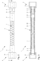
- Fig. 2 shows a schematic side view of the hose arrangement 1 in or for the (drinking) water-carrying system S, in particular for the drinking water pipe.
- Fig. 3 shows a schematic longitudinal section of the hose arrangement 1 according to Fig. 2 .
- the hose arrangement 1 has a hose 2 with a first hose end 3, on which a first connecting piece 4 is provided or formed, and a second hose end 5, on which a second connecting piece 6 is provided or formed.
- the connecting pieces 4, 6 are designed to connect the hose ends 3, 5 with a complementary connecting part of the consumer A or the water supply W, in particular the (corner) valve V.
- the hose 2 has a preferably corrugated main section 2A for guiding a water flow, in particular a drinking water flow.
- the main section 2A forms an inner tube.
- the hose 2 is preferably formed or shaped by a hose wall 2B or has a hose wall 2B.
- the hose wall 2B of the hose 2 is preferably corrugated or wave-shaped in the area of the main section 2A, as shown in particular in section Fig. 3 shown.
- the waveform is preferably sinusoidal or sinusoidal. This special wave shape preferably promotes a uniform, low-flow water flow through the main section 2A.
- the inner diameter of the main section 2A periodically varies or fluctuates - due to the wave shape - between a minimum diameter in the area of an inwardly directed wave crest and a maximum diameter in the area of an inwardly directed wave trough.
- the outside diameter varies or fluctuates accordingly.
- the wave-shaped design of the main section 2A or the hose wall 2B preferably extends over the entire length of the main section 2A.
- the wave-shaped design significantly improves the flexibility or flexibility of the hose arrangement 1 or the hose 2 or makes it possible in the first place depending on the hose material. This also makes it possible to use more stable materials, for example a high-performance plastic and/or a plastic from the group of polysulfones, such as polyphenylsulfone (PPSU), while still giving it the necessary flexibility. This is conducive to high stability of the hose arrangement 1 even under heavy loads.
- PPSU polyphenylsulfone
- main section 2A or the hose 2 in the area of the main section 2A with a smooth hose wall 2B or only partially corrugated hose wall 2B.
- the hose arrangement 1 or the hose 2 or the main section 2A preferably has/have an average inner diameter of at least 5 mm, preferably of at least 6 mm, particularly preferably of at least 7 mm and/or of at most 15 mm, preferably of at most 10 mm , particularly preferably of, for example, 8 mm. In principle, larger inner diameters are not excluded.
- the hose arrangement 1 or the hose 2 or the main section 2A or a casing 7 preferably has/have an average outside diameter of at least 8 mm, preferably of at least 9 mm, particularly preferably of at least 10 mm and/or of at most 20 mm, preferably of at most 15 mm, for example of 13 mm.
- the wall thickness or wall thickness of the hose 2 or main section 2A is preferably in the range from 0.5 mm to 5 mm, in particular in the range from 0.6 mm to 4 mm, particularly preferably in the range from 0.7 mm to 3 mm, very particularly preferably in the range from 0.8 mm to 2 mm. In principle, larger or smaller wall thicknesses are not excluded.
- the hose ends 3, 5 preferably have the same or a similar wall thickness as the main section 2A. However, it is also possible that the wall thicknesses of the hose ends 3, 5 are different from that of the main section 2A, for example larger.
- the hose ends 3, 5 preferably form a wave-free extension of the main section 2A, the outer diameter of the hose ends 3, 5 adjacent to the main section 2A having essentially the same outer diameter as the main section 2A.
- the hose ends 3, 5 adjacent to the main section 2A preferably have a larger inner diameter than the main section 2A, so that an expansion of the flow cross section is formed at the transition from the main section 2A to the hose ends 3, 5.
- the hose ends 3, 5 are preferably designed to be completely wave-free with a preferably cylindrical inner contour.
- the inner diameter of the hose ends 3, 5 can change in the axial direction, i.e. in the direction of the longitudinal extent of the hose 2 or the hose ends 3, 5.
- the hose 2 or the main section 2A and the hose ends 3, 5 are made in one piece. This is conducive to a particularly simple and cost-effective production and design of the hose 2. This also prevents the formation of leaks.
- the hose 2 is preferably manufactured by extrusion. Particularly for long hoses 2, the extrusion process offers the advantage that the hoses 2 produced are not subject to any length restrictions. Hoses 2 with different lengths can also be easily produced using an extrusion system. In principle, however, it is also possible to produce the hose 2 using a different production process.
- all parts of the hose 2, in particular the main section 2A and the different hose ends 3, 5 of the hose 2 are produced by extrusion in a common extrusion process. This enables a particularly simple and cost-effective production of the hose 2. In particular, no subsequent shaping or material-removing processing of the hose ends 3, 5 and/or connecting the hose ends 3, 5 to the main section 2A is necessary, so that the hose 2 can be obtained in just a few work steps.
- hose 2 it is possible to implement the production of the hose 2 as part of a continuous manufacturing process, i.e. in particular to produce several hoses 2 one after the other in an endless process. This is particularly advantageous in the context of series production.
- a casing 7, in particular a stainless steel or polyester braid, is provided.
- the casing 7 extends over the entire length of the main section 2A and preferably also extends partially over the hose ends 3, 5.
- a clamping element 8 in the form of a press sleeve is provided at each hose end 3, 5.
- the clamping elements 8 press the casing 7 on the circumference against the main section 2A and against the hose ends 3, 5. This is only about fastening the casing 7 and not connecting the hose 2 and the connecting pieces 4, 6 to one another.
- the preferred transition of the preferably corrugated main section 2A into the hose ends 3, 5 with essentially the same outer diameter preferably enables a secure support and/or compression of the casing 7 by means of the clamping element 8 and thus a kink-free design.
- clamping elements 8 can also be designed in several parts, for example in the form of two half-shells.
- the clamping elements 8 can also each be provided as a winding, preferably metal winding, in the area of the hose ends 3, 5.
- hose arrangement 1 or the hose 2 without a casing 7 and correspondingly without clamping elements 8 (not shown).
- PPSU polyphenylsulfone
- the maximum pressure resistance of the hose arrangement 1 or the hose 2 is at least 50 bar, more preferably 60 bar and/or preferably at most 80 bar. In this way it can be ensured that the hose arrangement 1 can be used for all systems S carrying drinking water, in particular for systems S with a high water pressure. In addition, the hose arrangement then offers sufficient security against bursting due to overpressure, leaks or other forms of material failure.
- the hose arrangement 1 or the hose 2 preferably has a maximum temperature resistance of greater than or equal to 90 ° C, in particular greater than or equal to 95 ° C, more preferably greater than or equal to 100 ° C, particularly preferably greater than or equal to 160 ° C , and/or a maximum temperature resistance of less than 200 °C, in particular less than 180 °C.
- a sufficiently high temperature resistance of the hose arrangement 1 or the hose 2 allows flushing with hot water, for example Kill pathogens and germs.
- the hose arrangement 1 or the hose 2 it is also possible for the hose arrangement 1 or the hose 2 to have a lower temperature resistance or for materials with lower temperature resistance to be used.
- the hose arrangement 1 or the hose 2 preferably has a tensile strength according to DIN EN 1113 of at least 300 N, in particular of at least 400 N, particularly preferably of at least 500 N.
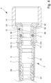
- Fig. 4 and 5 the hose arrangement 1 in the area of the first hose end 3 or the first connecting piece 4 formed at the hose end 3 will be explained in more detail.
- Fig. 4 shows a partial enlargement of Fig. 3 in the area of the first hose end 3 or first connecting piece 4.
- Fig. 5 shows a perspective view of the first hose end 3 or first connecting piece 4.
- the hose 2 or the first hose end 3 or the hose wall 2B preferably has an end face or end face 3A.
- the end face 3A is in particular annular and/or forms an outlet or inlet of the hose 2 or first hose end 3.
- the hose arrangement 1 has an adapter 9.
- the first connection piece 4 has the adapter 9 or the first connection piece 4 is at least partially formed by the adapter 9.
- the adapter 9 is arranged or can be arranged on the first hose end 3.
- the adapter 9 preferably consists of a plastic material or has a plastic material, for example from the family of polyamides, polyolefins or polysulfones, in particular polyamide 12, polypropylene, polyethylene and / or polyphenylsulfone (PPSU).
- the adapter 9 is preferably made of the same plastic material as the hose 2.
- the adapter 9 is particularly preferably manufactured by an injection molding process.
- adapter 9 can be produced cost-effectively within a short period of time by injection molding. At the same time, post-processing is required Adapter 9 is not necessary due to the process. Injection-molded components are particularly characterized by their cost-effective production and low material waste. However, it is also possible to produce the adapter 9 using a different manufacturing process, in particular for plastic components, for example also an abrasive process.
- the adapter 9 has a receptacle 10 for the first hose end 3 or forms such a receptacle 10.
- the first hose end 3, in particular at least partially or at the front, can be inserted/inserted into the receptacle 10, plugged in/inserted or picked up/received and/or the adapter 9 can be plugged/plugged onto the first hose end 3 or its end face 3A.
- the adapter 9 or its receptacle 10 preferably has a stop 9A for the hose 2 or the first hose end 3 or the end face 3A.
- the stop 9A limits the receptacle 10 at the end, in particular in such a way that the hose 2 or the first hose end 3 can only be pushed, inserted or picked up into the receptacle 10 up to the stop 9A.
- the stop 9A is preferably annular and/or forms an outlet or inlet of the adapter 9 or the hose arrangement 1.
- water can flow into the hose 2 or flow out of the hose 2 through the inlet or outlet formed by the stop 9A, in particular via the inlet or outlet of the hose 2 formed by the end face 3A.
- the inside diameter or flow cross section of the stop 9A is preferably greater than or equal to the inside diameter or the flow cross section of the end face 3A. In particular, there is no narrowing of the flow cross section of the hose arrangement 1 at the transition between the end face 3A and the stop 9A.
- the adapter 9 or the receptacle 10 preferably has an inner peripheral surface 9B.
- the receptacle 10 is particularly preferably formed between the inner peripheral surface 9B.
- the receptacle 10 is through the stop 9A, in particular in the axial direction or in the direction of the longitudinal extent of the hose arrangement 1, the hose 2, the first hose end 3 and/or the adapter 9, and through the inner peripheral surface 9B, in particular in the radial direction or in the direction transverse or perpendicular to the longitudinal extent of the hose arrangement 1, the hose 2, the first hose end 3 and/or the adapter 9, limited or defined.
- the first hose end 3 is accommodated or receivable in the adapter 9 or the receptacle 10 in such a way that an outer peripheral surface 3B of the hose 2 or hose end 3 faces the inner peripheral surface 9B of the adapter 9.
- the inner peripheral surface of the adapter 9 and the outer peripheral surface 3B of the hose 2 or hose end 3 to touch each other or to be spaced apart from one another. It is also possible for both areas in which the peripheral surfaces 3B, 9B touch each other and other areas in which the peripheral surfaces 3B, 9B are spaced apart from one another to be formed.
- the diameter of the outer peripheral surface of the hose 2 or hose end 3 preferably varies over the length of the hose end 3.
- the outer peripheral surface 3B is spaced from the inner peripheral surface 9B of the adapter 9 in the front or front region of the hose end 3.
- the hose 2 or the first hose end 3 preferably also has an outer peripheral surface 3B, which touches the inner peripheral surface 9B of the adapter 9 (in Fig. 4 directly behind the opening of the holder 10).
- other solutions are also possible here.
- the adapter 9 or the receptacle 10 is preferably hollow, in particular hollow cylindrical.
- the diameter of the inner peripheral surface 9B is constant or at least substantially constant.
- the adapter 9 or its receptacle 10 could also be conical, i.e. with an increasing or decreasing diameter of the inner peripheral surface 9B. It is also possible for the diameter of the inner peripheral surface 9B to vary in another way, for example initially decreasing and then increasing again. It is also possible for the adapter 9 or the inner peripheral surface 9B to have one or more beads or the like in which the diameter of the inner peripheral surface 9B is reduced and/or one or more depressions or the like in which the Diameter of the inner peripheral surface 9B is increased.
- the adapter 9 or the receptacle 10 corresponds to the first hose end 3, in particular the inner circumferential surface 9B or its diameter corresponds at least substantially to the outer circumferential surface 3B or its diameter.
- the adapter 9 or the receptacle 10 is also preferably at least essentially conical.
- the first hose end 3 is accommodated or receivable in the receptacle 10 of the adapter 9 in such a way that there is no narrowing of the flow cross section.
- the hose 2 or the first hose end 3 or the hose wall 2B is not compressed or compressed when the adapter 9 is arranged or fixed on the first hose end 3.
- the minimum flow cross section of the hose arrangement 1 with the adapter 9 arranged, fixed or secured at the first hose end 3 corresponds to at least the minimum flow cross section of the hose 2 itself and/or the hose arrangement 1 without the adapter 9 arranged at the first hose end 3.
- the adapter 9 preferably has no influence on the minimum flow cross section of the hose arrangement 1 or the hose 2 or does not cause any change in the minimum flow cross section.
- a seal 11 is formed or formed between the adapter 9 or the inner peripheral surface 9B on the one hand and the hose 2 or the first hose end 3 or the outer peripheral surface 3B on the other hand.
- the seal 11 is preferably designed as a sealing element, in particular as a sealing ring.
- the seal 11 or the sealing ring is preferably arranged or can be arranged in a recess or groove, in particular on the circumferential side, of the hose 2 or the first hose end 3.
- the seal 11 could alternatively or additionally be provided in a recess or groove in the adapter 9.
- a seal 11 is formed directly between the inner peripheral surface 9B of the adapter 9 and the outer peripheral surface 3B of the first hose end 3.
- This can be achieved in particular by a press fit of the first hose end 3 in the adapter 9 or the receptacle 10.
- the first hose end 3 then has an outer peripheral surface 3B, which is at least partially larger than the inner peripheral surface 9B of the adapter 9.
- the flow cross section of the hose 2 is not or only slightly reduced when it is inserted into the adapter 9.
- a front seal it is also possible to provide a front seal.
- a further seal (not shown) is then formed between the end face 3A and the stop 9A.
- a further sealing element such as a sealing ring, can be provided on the end face 3A and/or the stop 9A.
- the hose arrangement 1 has a locking part 12.
- the locking part 12 is designed separately from the hose 2 and adapter 9 or forms a separate component of the hose arrangement 1.
- the hose 2, the adapter 9 and the locking part 12 are separate components of the hose arrangement 1.
- the adapter 9 and the locking part 12 preferably form an adapter arrangement.
- the locking part 12 is made of metal or has a metal, for example steel.
- the locking part 12 is made of or has a different material, in particular plastic.
- the locking part 12 is a metal sheet or is made from a metal sheet.
- the locking part 12 is preferably arranged or can be arranged on the first hose end 3.
- the first connecting piece 4 preferably has the locking part 12 or the first connecting piece 4 is at least partially formed by the locking part 12.
- the adapter 9 is secured/secured or held/durable or fastened/fastenable to the hose 2 or first hose end 3 by means of the locking part 12. When the adapter 9 is secured, it is not possible to remove or separate the adapter 9 from the hose 2 or the first hose end 3.
- the adapter 9 through the locking part 12 on the hose 2 or first hose end 3 in the axial direction or in the longitudinal direction, i.e. in the direction of the longitudinal extent of the hose arrangement 1, the hose 2, the first hose end 3 and / or the adapter 9, fixed or fixable.
- the adapter 9 can also be fixed or fixable in the radial direction, i.e. in a direction transverse or perpendicular to the longitudinal extent of the hose arrangement 1, the hose 2, the first hose end 3 and/or the adapter 9, and/or against rotation.
- this is only optional. It is therefore possible for the adapter 9 to be secured or held captively on the hose 2 or first hose end 3 only in the axial direction, but can still rotate relative to the hose 2 or first hose end 3.
- the hose 2 or the first hose end 3 has a form-fitting section 13 or forms one.
- the form-fitting section 13 is shaped or formed in particular in or on the first hose end 3, particularly preferably in one piece with the first hose end 3, in particular by the hose wall 2B.
- the form-fitting section 13 particularly preferably corresponds to the locking part 12.
- the form-fitting section 13 preferably runs circumferentially around the hose 2 or the first hose end 3, in particular over the full circumference.
- a form-fitting section 13 which only partially extends over the circumference of the hose 2 or first hose end 3, for example only over half the circumference.
- the locking part 12 forms a positive connection with the positive locking section 13 or is designed for this purpose.
- the adapter 9 is secured or can be secured by the positive fit on the first hose end 3.
- the adapter 9 is fixed or can be fixed in the axial direction or longitudinal direction by the positive fit on the first hose end 3.
- the locking part 12 particularly preferably blocks movement of the adapter 9 in the axial direction or longitudinal direction or is designed for this purpose.
- the form-fitting section 13 is preferably formed as a recess or groove in the first hose end 3 or hose 2.
- the form-fitting section 13 is formed by or in the hose wall 2B.
- the thickness of the hose wall 2B in the area of the form-fitting section 13 corresponds at least substantially to the wall thickness outside the form-fitting section 13, as in Fig. 4 shown.
- the form-fitting section 13 forms or has a shoulder 13A.
- the shoulder 13A is formed in particular by one side of the groove.
- the form-fitting section 13 can also be designed as a step of the hose wall 2B, so that a corresponding shoulder 13A is formed.
- the locking part 12 engages in the form-fitting section 13 and/or engages behind the form-fitting section 13 and/or the shoulder 13A or is designed for this purpose.
- the positive connection is or is preferably produced via the engagement and/or rear grip. It is also possible for the locking part 12 to be tensioned or tensionable against the shoulder 13A.
- the locking part 12 is preferably at least essentially flat, plate-shaped and/or disc-shaped.
- the locking part 12 is particularly preferably designed as a locking plate or locking disk, as in particular in Fig. 5 shown.
- Fig. 5 is a perspective view in which the hose 2 or the first hose end 3 is cut directly behind the locking part 12.
- the locking part 12 is rod-shaped and/or designed as a locking bar or the like.
- the locking part 12 is preferably at least substantially U-shaped.
- the locking part 12 can preferably be inserted transversely, in particular perpendicularly, to the longitudinal extent of the hose 2 or first hose end 3 into the form-fitting section 13 or pushed onto the form-fitting section 13.
- the locking part 12 is held immovably in the form-fitting section 13.
- the adapter 9 preferably has two projections which block the locking part 12 laterally.
- the adapter 9 is releasably secured or securable on the hose 2 or first hose end 3 and/or the positive connection 13 between the locking part 12 and the positive locking section 13 is reversible and/or the locking part 12 is removable.
- the adapter 9 is permanently held or secured on the hose 2 or the first hose end 3 and/or in which the positive connection is irreversible and/or in which the locking part 12 is no longer removed after the positive connection has been established can be.
- the locking part 12 can optionally have a projection 12A, which extends transversely, in particular perpendicularly, to the main plane of extension of the locking part 12 or in the longitudinal extension of the hose arrangement 1 (in Fig. 5 the projection 12A is shown in dashed lines, since it actually only lies behind the in Fig. 5 section shown).
- the projection 12A preferably enables or facilitates pulling out or removing the locking part 12 and/or ensures additional stability or retention of the locking part 12 in the form-fitting section 13.
- the hose 2 or its first hose end 3 can be inserted/inserted, inserted/inserted or recorded/recorded into the receptacle 10 of the adapter 9 up to the form-fitting section 13.
- the form-fitting section 13 is preferably arranged outside the receptacle 10 or can be arranged, particularly preferably immediately or directly behind the receptacle 10.
- the longitudinal extent of the receptacle 10 preferably corresponds at least substantially to the longitudinal extent of the hose end 3 from the form-fitting section 13 to the end face 3A.
- the corrugated main section 2A is initially followed by an at least essentially flat or smooth hose section 2C, which in turn is followed by the form-fitting section 13.
- this is advantageous because the casing 7 or the clamping element 8 can rest against the smooth section 2C.
- the form-fitting section 13 is then only formed where the hose 2 or the first hose end 3 is no longer covered.
- the smooth hose section 2C can be dispensed with and the form-fitting section 13 can connect directly to the main section 2A. It is also possible for the form-fitting section 13 to be formed by a shaft of the main section 2A, for example the last shaft of the main section 2A.
- the adapter 9 preferably has a fastening section 9C for fastening or connecting the hose arrangement 1 to a water supply W and/or, particularly preferably, a customer A.
- the fastening section 9C preferably forms a shoulder or an abutment for a first clamping element 14 of the hose arrangement 1, in particular a union nut.
- the fastening section 9C is formed in particular on the circumference of the adapter 9 and/or extends in the radial direction or transversely to the longitudinal extent of the hose arrangement 1 or the hose 2 or the adapter 9.
- the hose arrangement 1 can preferably be connected to a corresponding connection part of a water supply W and/or, particularly preferably, of a consumer A via the clamping element 14.
- the clamping element 14 has an internal thread for this purpose, in particular for a corresponding external thread of the corresponding connecting part.
- the first connecting piece 4 is formed by the adapter 9 with the clamping element 14 or the first connecting piece 4 has the adapter 9 and the clamping element 14.
- the clamping element 14 is preferably held captively on the hose arrangement 1 or the hose 2.
- the clamping element 14 is pulled onto the hose 2 before the adapter 9 is arranged on the first hose end 3.
- the clamping element 14 preferably has an opening with a larger diameter than the hose 2 or the first hose end 3.
- the adapter 9 is then arranged and secured at the first hose end 3, in particular by means of the locking part 12.
- the shoulder formed by the fastening section 9C of the adapter 9 preferably has a larger diameter than the opening of the clamping element 14, so that the clamping element 14 can no longer be pulled from the first hose end 3 or separated from the hose arrangement 1 via the first hose end 3 or . so that the clamping element 14 can be clamped against the fastening section 9C for connection to the corresponding connection part.
- the locking part 12 can form a stop for the clamping element 14 if the locking part 12 protrudes far enough radially from the hose arrangement 1 (not shown). In this way it can be prevented that the clamping element 14 slips beyond the first hose end 3 onto the hose 2 or the main section 2A.
- the adapter 9 or the fastening section 9C can be connected directly to a corresponding connection part.
- the adapter 9 can have an external thread or the fastening section 9C can be designed as an external thread, so that the hose arrangement 1 can be screwed into a corresponding internal thread of a corresponding connecting part.
- the union nut can be omitted.
- the adapter 9 then preferably forms the first connection piece 4.
- Fig. 6 shows an enlarged section of the hose arrangement 1 according to Fig. 3 in the area of the second hose end 5 or second connecting piece 6.
- a (second) fastening section 5A is formed for connecting the hose arrangement 1 to a corresponding connection part of a customer A and/or, particularly preferably, a water supply W.
- the fastening section 5A is formed or shaped by the hose 2 or the second hose end 5 or the hose wall 2B.
- the attachment portion 5A is formed or shaped integrally with the hose 2.
- the fastening section 5A preferably adjoins the main section 2A of the hose 2 in one piece.
- the fastening section 5A is formed or shaped in a common extrusion process with the main section 2A or hose 2 or second hose end 5.
- the fastening section 5A is preferably designed as a shoulder or has a shoulder.
- the fastening section 5A is formed in particular on the circumference of the hose 2 or the second hose end 5 and/or extends in the radial direction or transversely to the longitudinal extent of the hose arrangement 1 or the hose 2 or the second hose end 5.
- the fastening section 5A preferably forms a shoulder or an abutment or a stop for a second clamping element 15, in particular a union nut.
- the hose arrangement 1 can preferably be connected to a corresponding connection part of a customer A and/or, particularly preferably, a water supply W via the clamping element 15.
- the clamping element 15 preferably has an internal thread, in particular for a corresponding external thread of the corresponding connecting part.
- the second connecting piece 6 is formed or shaped by the second clamping element 15 on the one hand and the second hose end 5 and/or the fastening section 5A on the other hand, or the second connecting piece 6 has the clamping element 14 on the one hand and the second hose end 5 and/or the fastening section 5A on the other hand on.
- the second connecting piece 6 or parts of the connecting piece 6 are formed in one piece with the hose 2.
- the second hose end 5 or the fastening section 5A can be connected directly to a corresponding connection part.
- the fastening section 5A can be designed as an external thread for a corresponding internal thread of the corresponding connecting part.
- the clamping element 15, in particular a union nut can be dispensed with.
- the second hose end 5 and/or the fastening section 5A then preferably forms the second connecting piece 6.
- the second connecting piece 6 is then formed in one piece with the hose 2.
- the second hose end 5 preferably has a radially circumferential holding area and/or receiving area 5B on the front side for holding and/or receiving a sealing element 16, preferably a sealing ring.
- the sealing element 16 can preferably be pushed and/or plugged onto the receiving area up to the fastening section 5A or the shoulder formed thereby. Additionally or alternatively, a radial seal can also be provided.
- two clamping elements 14, 15 are preferably provided.
- a fastening section 9C for the first clamping element 14 is formed by the adapter 9, while a fastening section 5A for the second clamping element 15 is formed by the second hose end 5 or in one piece with the hose 2.
- the clamping elements 14, 15 are preferably held captively on the hose arrangement 1 or the hose 2, in particular between the fastening sections 9C and 5A.
- the clamping elements 14, 15 are particularly preferably both pulled onto the hose 2 via the first hose end 3 and then the adapter 9 is arranged or secured on the first hose end 3, so that a fastening section 9C, 5A is formed on both hose ends 3, 5.
- the clamping elements 14, 15 are designed in the same way. However, depending on requirements, it is possible for the clamping elements 14, 15 to be designed differently, for example to have different internal diameters, to have different internal threads or the like.
- a locking element 14, 15 is also possible for a locking element 14, 15 to be provided only at one hose end 3, 5 or connecting piece 4, 6.
- the corresponding fastening section 5A, 9C is then preferably designed directly for connection, for example as a thread.
- the hose ends 3, 5 or connecting pieces 4, 6 of the hose arrangement 1 are preferably designed differently, as described above.
- the second hose end 5 or connecting piece 6 preferably does not have an adapter 9.
- the hose arrangement 1 has an adapter 9 at both hose ends 3, 5.
- the second hose end 5 is then preferably designed to be connected to an adapter 9, as previously described in relation to the first hose end 3.
- the adapters 9 on the first and second hose ends 3, 5 can be designed the same or different.
- the hose arrangement 1 is designed for drinking water installations or is suitable for carrying drinking water or coming into contact with drinking water.
- the components of the hose arrangement 1 can also include other elements or materials, for example sealing elements, adhesives, the casing 7 or the like.
- “Drinking water installation” in the sense of the present invention is preferably the entirety of the pipes, fittings and apparatus that are located between the point of transfer of drinking water from a water supply system, for example waterworks, to the user and the point of withdrawal of drinking water.
- “Drinking water” is preferably understood to mean water for human use, in particular for consumption.
- the German “Ordinance on the Quality of Water for Human Use” contains definitions and protective regulations for drinking water. This represents an implementation of the EC Directive 98/83/EC "On the quality of water intended for human consumption” into national law. "Drinking water” in the sense of the present invention is preferably as in the EC Directive or its national implementations , especially as defined in the German Drinking Water Ordinance.
- Drinking water is all water that, in its original state or after treatment, is intended for drinking, cooking, preparing food and drinks, personal hygiene and cleaning, cleaning objects that come into contact with food as intended or for cleaning of objects that are intended to come into more than just temporary contact with the human body. Furthermore, drinking water is any water used in a food establishment for the production, treatment, preservation or marketing of products or substances intended for human consumption.
- Drinking water must be such that there is no risk of harm to human health, particularly through pathogens, through its consumption or use. Furthermore, it must be pure and fit for consumption. In particular, drinking water must not contain pathogens and chemical substances in concentrations that could cause harm to human health. Concentrations of microorganisms and chemical Substances that can contaminate drinking water or have a detrimental effect on its properties should be kept as low as is possible according to the generally accepted rules of technology with reasonable effort, taking individual cases into account. Furthermore, drinking water must not contain any substances that contain one or more radionuclides whose activity or concentration cannot be ignored from the point of view of radiation protection.
- microorganisms, chemical substances and radioactive substances do not exceed the limit values specified in Annexes 1-3 of the German Drinking Water Ordinance.
- the hose arrangement 1 preferably meets the "requirements for systems for the extraction, treatment or distribution of drinking water" in accordance with Section 17 of the German Drinking Water Ordinance.
- the hose arrangement 1 may not directly or indirectly reduce the protection of human health provided for in the Drinking Water Ordinance, subsequently change the smell or taste of the water or release substances into the drinking water in quantities that are greater than would be the case if the generally accepted rules of technology are adhered to is unavoidable.
- the components of the hose arrangement 1 are preferably chemically compatible with each other and with the water to be passed through.
- the components of the hose arrangement 1 therefore preferably do not enter into any chemical reactions with one another or with water.
- no corrosion occurs and/or the components of the hose arrangement 1 are chemically resistant and in particular retain their characteristic properties despite contact with other components of the hose arrangement 1 and/or with water for any length of time.
- the components or materials of the hose arrangement 1 that come into contact with water for human use particularly preferably all materials or components of the hose arrangement 1, do not pose a health risk and preferably do not cause any changes to the drinking water in terms of its nature or appearance, smell or taste out.
- the testing of the hose arrangement 1 to ensure that it is suitable for drinking water installations, in particular that it meets the requirements of the Drinking Water Ordinance, is preferably carried out in accordance with the specifications in accordance with "DVGW KTW” or “DVGW W 270", particularly preferably in accordance with the " Guideline for the hygienic assessment of organic materials in contact with drinking water” (KTW guideline) of the German Federal Environment Agency or according to the "Evaluation basis for plastics and other organic materials in contact with drinking water” (KTW-BWGL) of the German Federal Environment Agency.
- the hose arrangement 1 is then checked in particular for migration of substances and promotion of microbial growth.
- the testing of the hose arrangement 1 is preferably carried out on the finished end product, but can also be carried out additionally or alternatively separately for individual components of the hose arrangement 1, for example the hose 2, the adapter 9 or the locking part 12.
- the test of the hose arrangement 1 for migration of substances is preferably carried out by filling the hose arrangement 1 or the hose 2 with (dechlorinated) drinking water.
- the testing of the hose ends 3, 5 and/or the adapter 9 and/or locking part 12 is preferably also carried out by immersing them in (dechlorinated) drinking water.
- the resulting water is referred to below as migration water.
- the test is preferably carried out with cold water as well as with warm water and hot water.
- Cold water is preferably water with a temperature between 21 °C and 25 °C, in particular 23 °C.
- Hot water is preferably water with a temperature between 58 °C and 62 °C, in particular 60 °C.
- Hot water is preferably water with a temperature between 83 °C and 87 °C, in particular 85 °C.
- the migration water is preferably brought into contact with the hose arrangement 1 or its components for 10 days, particularly preferably for 31 days.
- the migration waters are tested for migration of substances, in particular the parameters of odor, turbidity, color, foam formation and total organic carbon (Total Organic Carbon, TOC).
- the test is preferably carried out in accordance with DIN EN 1420 and/or DIN EN 12873.
- the limit values specified in the KTW guidelines or the KTW assessment basis or other suitable guidelines or assessment bases are not exceeded by the migration water after 10 days of contact, in particular after 31 days of contact, with the hose arrangement 1 or its components.
- no increasing trend in the parameters can be determined over the measurement period.
- test with regard to the promotion of microbial growth is preferably carried out in accordance with DIN EN 16421, in particular the biomass production potential method (BPP method) or the volumetric method described therein.
- the hose arrangement 1 or the hose 2, the adapter 9 and the blocking part 12 only have a firmly adhering surface colonization or surface growth in all test periods examined, which is less than or equal to 0.07 ml / 800 cm 2 , in particular less than or equal to 0.05 ml / 800 cm 2 .
- the hose arrangement 1 or its components preferably has/have surface growth or surface colonization greater than 0, and therefore has/have no biocidal effect on the drinking water.
Landscapes
- Engineering & Computer Science (AREA)
- General Engineering & Computer Science (AREA)
- Mechanical Engineering (AREA)
- Health & Medical Sciences (AREA)
- Life Sciences & Earth Sciences (AREA)
- Hydrology & Water Resources (AREA)
- Public Health (AREA)
- Water Supply & Treatment (AREA)
- Rigid Pipes And Flexible Pipes (AREA)
Claims (11)
- Agencement de tuyau (1) pour un système transportant de l'eau (S) destiné à la conduite d'eau potable dans un système transportant de l'eau potable (S),l'agencement de tuyau (1) présentant un tuyau (2) doté d'une première extrémité de tuyau (3), sur laquelle est formée une première pièce de raccord (4), et d'une seconde extrémité de tuyau (5) opposée à la première extrémité de tuyau (3), sur laquelle est formée une seconde pièce de raccord (6),les pièces de raccord (4, 6) étant conçues pour le raccordement des extrémités de tuyau (3, 5) à une pièce de raccord réalisée de manière respectivement complémentaire d'un consommateur (A) ou d'une alimentation en eau (W),l'agencement de tuyau (1) présentant un adaptateur (9) doté d'un logement (10) pour la première extrémité de tuyau (3) du tuyau (2),la première pièce de raccord (4) présentant l'adaptateur (9) ou étant au moins partiellement formée par l'adaptateur (9),l'agencement de tuyau (1) présentant un segment de liaison par complémentarité de forme (13), qui est formé par le tuyau (2), et une pièce de blocage (12) séparée du tuyau (2) et de l'adaptateur (9), l'adaptateur (9) étant ou pouvant être protégé d'une séparation d'avec le tuyau (2) par la formation d'une liaison par complémentarité de forme entre la pièce de blocage (12) et le segment de liaison par complémentarité de forme (13),un segment de fixation (5A) pour le raccordement à un consommateur (A) ou une alimentation en eau (W) étant formée d'un seul tenant avec le tuyau (2) sur la seconde extrémité de tuyau (5) du tuyau (2), etla résistance maximale à la pression de l'agencement de tuyau (1) étant d'au moins 50 bar.
- Agencement de tuyau selon la revendication 1, caractérisé en ce que la pièce de blocage (12) est une rondelle de blocage.
- Agencement de tuyau selon la revendication 1 ou 2, caractérisé en ce que le segment de liaison par complémentarité de forme (13) forme une rainure, dans laquelle la pièce de blocage (12) vient ou peut venir en prise.
- Agencement de tuyau selon l'une des revendications précédentes, caractérisé en ce que le segment de liaison par complémentarité de forme (13) présente ou forme un épaulement, à l'arrière duquel la pièce de blocage (12) vient ou peut venir se bloquer, de telle sorte qu'une séparation du tuyau (2) d'avec l'adaptateur (9) est ou peut être bloquée.
- Agencement de tuyau selon l'une des revendications précédentes, caractérisé en ce que l'adaptateur (9) est ou peut être fixé de manière libérable sur le tuyau (2).
- Agencement de tuyau selon l'une des revendications précédentes, caractérisé en ce que l'agencement de tuyau (1) présente, lorsque la première extrémité de tuyau (3) est reçue dans l'adaptateur (9), une section de passage minimale, qui correspond au moins à la section de passage minimale du tuyau (2).
- Agencement de tuyau selon l'une des revendications précédentes, caractérisé en ce qu'un joint d'étanchéité (11) est disposé ou formé entre la surface circonférentielle extérieure (3B) de la première extrémité de tuyau (3) et la surface circonférentielle intérieure (9B) de l'adaptateur (9) ou de son logement (10).
- Agencement de tuyau selon l'une des revendications précédentes, caractérisé en ce que l'adaptateur (9) forme un segment de fixation (9C), en particulier un épaulement ou un filet, pour le raccordement, en particulier au moyen d'un élément de serrage (9) tel qu'un écrou-raccord, de l'agencement de tuyau (1) à une pièce de raccord correspondante.
- Agencement de tuyau selon l'une des revendications précédentes, caractérisé en ce que le tuyau (2) est fabriqué en une matière plastique à haute performance et/ou une matière plastique du groupe des polysulfones, en particulier le polyphénylsulfone.
- Agencement de tuyau selon l'une des revendications précédentes, caractérisé en ce que le logement (10) correspond à la première extrémité de tuyau (3) de telle manière que la première extrémité de tuyau (3) est ou peut être disposée à l'intérieur du logement (10) et qu'une surface circonférentielle intérieure (9B) du logement (10) est alors tournée vers une surface circonférentielle extérieure (3B) de la première extrémité de tuyau (3).
- Utilisation d'un agencement de tuyau (1) selon l'une des revendications 1 à 10 dans un système transportant de l'eau potable (S), de préférence dans un ou pour un appareil de robinetterie sanitaire.
Applications Claiming Priority (1)
| Application Number | Priority Date | Filing Date | Title |
|---|---|---|---|
| DE102019003605.0A DE102019003605A1 (de) | 2019-05-23 | 2019-05-23 | Schlauchanordnung, Adapteranordnung und Verwendung |
Publications (3)
| Publication Number | Publication Date |
|---|---|
| EP3742034A1 EP3742034A1 (fr) | 2020-11-25 |
| EP3742034C0 EP3742034C0 (fr) | 2023-10-18 |
| EP3742034B1 true EP3742034B1 (fr) | 2023-10-18 |
Family
ID=70802762
Family Applications (1)
| Application Number | Title | Priority Date | Filing Date |
|---|---|---|---|
| EP20175968.5A Active EP3742034B1 (fr) | 2019-05-23 | 2020-05-22 | Agencement de tuyau et utilisation |
Country Status (2)
| Country | Link |
|---|---|
| EP (1) | EP3742034B1 (fr) |
| DE (1) | DE102019003605A1 (fr) |
Families Citing this family (3)
| Publication number | Priority date | Publication date | Assignee | Title |
|---|---|---|---|---|
| TWI708905B (zh) * | 2019-12-25 | 2020-11-01 | 葳仂特國際有限公司 | 軟管可旋轉接頭 |
| DE102020104733A1 (de) | 2020-02-24 | 2021-08-26 | Grohe Ag | Vorrichtung zur Verbindung eines Flüssigkeitsschlauchs an einem Ventil |
| DE202021101421U1 (de) * | 2021-03-19 | 2022-06-21 | Neoperl Gmbh | Leitungskupplungsstück und korrespondierende Verwendung |
Family Cites Families (10)
| Publication number | Priority date | Publication date | Assignee | Title |
|---|---|---|---|---|
| US4453747A (en) * | 1982-06-01 | 1984-06-12 | Bimba Charles W | Connector system for flexible tubing |
| DE19654435C2 (de) * | 1996-12-30 | 2000-08-31 | Oventrop Sohn Kg F W | Anordnung zur steckbaren Verbindung von Rohren oder Schläuchen mit Armaturen oder Fittings |
| GB0004921D0 (en) | 2000-03-02 | 2000-04-19 | Waterleau Global Water Technol | System for sustainable treatment of municipal and industrial wastewater |
| ITVA20040021U1 (it) * | 2004-12-10 | 2005-03-10 | Whirlpool Co | Dispositivo di collegamento rapido di tubazioni di lavatrici e simili |
| DE102008039991B3 (de) * | 2008-08-27 | 2009-10-29 | Kottmann Gosla Gmbh | Druckschlauch für ein wasserführendes System, insbesondere zum Anschließen von beweglichen Sanitärarmaturen oder zum Verbinden von Teilen des wasserführenden Systems |
| DE102010037669B4 (de) * | 2010-09-21 | 2017-11-30 | Miele & Cie. Kg | Ablaufschlauch für ein wassergespeistes Haushaltsgerät |
| DE102016104477A1 (de) * | 2016-03-11 | 2017-09-14 | Witzenmann Gmbh | Brauseschlauch |
| DE102017002275A1 (de) * | 2017-03-10 | 2018-09-13 | Uniwell Rohrsysteme Gmbh & Co. Kg | Druckschlauch |
| US10591098B2 (en) * | 2017-06-29 | 2020-03-17 | E. Mishan & Sons, Inc. | Garden hose with metal sheath |
| DE202017105078U1 (de) * | 2017-08-24 | 2018-11-29 | Halograph (Pty) Ltd | Verbindungsanordnung |
-
2019
- 2019-05-23 DE DE102019003605.0A patent/DE102019003605A1/de active Pending
-
2020
- 2020-05-22 EP EP20175968.5A patent/EP3742034B1/fr active Active
Also Published As
| Publication number | Publication date |
|---|---|
| EP3742034C0 (fr) | 2023-10-18 |
| DE102019003605A1 (de) | 2020-11-26 |
| EP3742034A1 (fr) | 2020-11-25 |
Similar Documents
| Publication | Publication Date | Title |
|---|---|---|
| EP3742034B1 (fr) | Agencement de tuyau et utilisation | |
| EP2865815B1 (fr) | Robinetterie sanitaire | |
| DE202004015232U1 (de) | Fitting für Flüssigkeit mit Dampf | |
| EP2582890B1 (fr) | Unité d'insertion sanitaire et accessoire de douchette pourvu d'une unité d'insertion sanitaire | |
| DE202014006320U1 (de) | Anschlussvorrichtung und sanitäre Anlage | |
| EP1646820A1 (fr) | Element de raccord filete et gaine protectrice pour celui-ci | |
| DE102017002275A1 (de) | Druckschlauch | |
| EP3663471B1 (fr) | Procédé de fabrication d'un tuyau et tuyau | |
| DE202019103965U1 (de) | Schlauch und Anschlussgarnitur, Auslaufgarnitur und Armatur mit einem Schlauch | |
| DE102013017781A1 (de) | Sanitäre Auslaufarmatur | |
| DE102010023962A1 (de) | Dichtring, Durchflussmengenregler sowie Brausearmatur mit einem Durchflussmengenregler | |
| DE102018118617A1 (de) | Rastbolzen mit geschützter Rastmechanik | |
| DE102007022799B4 (de) | Vorrichtung zum Verbinden zweier Enden von Rohr- oder Schlauchleitungen | |
| DE19529189A1 (de) | Anschlußstück | |
| DE102008051303A1 (de) | Verschlusskupplung | |
| DE202017105078U1 (de) | Verbindungsanordnung | |
| EP0811799B1 (fr) | Appareil de perçage avec vanne pour tuyaux de distribution à fluide sous pression en matière plastique | |
| EP0804970B1 (fr) | Pistolet de pulvérisation à main pour appareil de nettoyage haute pression | |
| DE102014005837B3 (de) | Schlauchkupplung | |
| DE102007019627B3 (de) | Messvorrichtung | |
| EP3900908B1 (fr) | Tuyau résistant à la pression | |
| DE102014209817B4 (de) | Schlaucheinrichtung zum Transportieren von Fluiden für ein Haushaltsgerät, Vorrichtung, Haushaltsgerät sowie Verfahren | |
| DE102020123725B4 (de) | Filtereinheit zur Aufnahme einer Filterkartusche | |
| DE102019106128A1 (de) | Verfahren zum Spülen einer leitungsgebundenen Trinkwasserabgabevorrichtung sowie dazu eingerichtete leitungsgebundene Trinkwasserabgabevorrichtung | |
| DE102005038404B4 (de) | Zapfarmatur |
Legal Events
| Date | Code | Title | Description |
|---|---|---|---|
| PUAI | Public reference made under article 153(3) epc to a published international application that has entered the european phase |
Free format text: ORIGINAL CODE: 0009012 |
|
| STAA | Information on the status of an ep patent application or granted ep patent |
Free format text: STATUS: THE APPLICATION HAS BEEN PUBLISHED |
|
| AK | Designated contracting states |
Kind code of ref document: A1 Designated state(s): AL AT BE BG CH CY CZ DE DK EE ES FI FR GB GR HR HU IE IS IT LI LT LU LV MC MK MT NL NO PL PT RO RS SE SI SK SM TR |
|
| AX | Request for extension of the european patent |
Extension state: BA ME |
|
| STAA | Information on the status of an ep patent application or granted ep patent |
Free format text: STATUS: REQUEST FOR EXAMINATION WAS MADE |
|
| 17P | Request for examination filed |
Effective date: 20210518 |
|
| RBV | Designated contracting states (corrected) |
Designated state(s): AL AT BE BG CH CY CZ DE DK EE ES FI FR GB GR HR HU IE IS IT LI LT LU LV MC MK MT NL NO PL PT RO RS SE SI SK SM TR |
|
| STAA | Information on the status of an ep patent application or granted ep patent |
Free format text: STATUS: EXAMINATION IS IN PROGRESS |
|
| 17Q | First examination report despatched |
Effective date: 20220824 |
|
| GRAP | Despatch of communication of intention to grant a patent |
Free format text: ORIGINAL CODE: EPIDOSNIGR1 |
|
| STAA | Information on the status of an ep patent application or granted ep patent |
Free format text: STATUS: GRANT OF PATENT IS INTENDED |
|
| RIC1 | Information provided on ipc code assigned before grant |
Ipc: F16L 15/00 20060101ALN20230419BHEP Ipc: F16L 47/04 20060101ALN20230419BHEP Ipc: E03C 1/02 20060101ALI20230419BHEP Ipc: F16L 33/00 20060101ALI20230419BHEP Ipc: F16L 33/28 20060101ALI20230419BHEP Ipc: F16L 11/15 20060101ALI20230419BHEP Ipc: F16L 37/14 20060101ALI20230419BHEP Ipc: F16L 33/22 20060101ALI20230419BHEP Ipc: F16L 19/028 20060101AFI20230419BHEP |
|
| INTG | Intention to grant announced |
Effective date: 20230510 |
|
| GRAS | Grant fee paid |
Free format text: ORIGINAL CODE: EPIDOSNIGR3 |
|
| GRAA | (expected) grant |
Free format text: ORIGINAL CODE: 0009210 |
|
| STAA | Information on the status of an ep patent application or granted ep patent |
Free format text: STATUS: THE PATENT HAS BEEN GRANTED |
|
| AK | Designated contracting states |
Kind code of ref document: B1 Designated state(s): AL AT BE BG CH CY CZ DE DK EE ES FI FR GB GR HR HU IE IS IT LI LT LU LV MC MK MT NL NO PL PT RO RS SE SI SK SM TR |
|
| REG | Reference to a national code |
Ref country code: GB Ref legal event code: FG4D Free format text: NOT ENGLISH |
|
| REG | Reference to a national code |
Ref country code: CH Ref legal event code: EP |
|
| REG | Reference to a national code |
Ref country code: IE Ref legal event code: FG4D Free format text: LANGUAGE OF EP DOCUMENT: GERMAN |
|
| REG | Reference to a national code |
Ref country code: DE Ref legal event code: R096 Ref document number: 502020005666 Country of ref document: DE |
|
| U01 | Request for unitary effect filed |
Effective date: 20231109 |
|
| U07 | Unitary effect registered |
Designated state(s): AT BE BG DE DK EE FI FR IT LT LU LV MT NL PT SE SI Effective date: 20231115 |
|
| PG25 | Lapsed in a contracting state [announced via postgrant information from national office to epo] |
Ref country code: GR Free format text: LAPSE BECAUSE OF FAILURE TO SUBMIT A TRANSLATION OF THE DESCRIPTION OR TO PAY THE FEE WITHIN THE PRESCRIBED TIME-LIMIT Effective date: 20240119 |
|
| PG25 | Lapsed in a contracting state [announced via postgrant information from national office to epo] |
Ref country code: IS Free format text: LAPSE BECAUSE OF FAILURE TO SUBMIT A TRANSLATION OF THE DESCRIPTION OR TO PAY THE FEE WITHIN THE PRESCRIBED TIME-LIMIT Effective date: 20240218 |
|
| PG25 | Lapsed in a contracting state [announced via postgrant information from national office to epo] |
Ref country code: ES Free format text: LAPSE BECAUSE OF FAILURE TO SUBMIT A TRANSLATION OF THE DESCRIPTION OR TO PAY THE FEE WITHIN THE PRESCRIBED TIME-LIMIT Effective date: 20231018 |
|
| PG25 | Lapsed in a contracting state [announced via postgrant information from national office to epo] |
Ref country code: IS Free format text: LAPSE BECAUSE OF FAILURE TO SUBMIT A TRANSLATION OF THE DESCRIPTION OR TO PAY THE FEE WITHIN THE PRESCRIBED TIME-LIMIT Effective date: 20240218 Ref country code: GR Free format text: LAPSE BECAUSE OF FAILURE TO SUBMIT A TRANSLATION OF THE DESCRIPTION OR TO PAY THE FEE WITHIN THE PRESCRIBED TIME-LIMIT Effective date: 20240119 Ref country code: ES Free format text: LAPSE BECAUSE OF FAILURE TO SUBMIT A TRANSLATION OF THE DESCRIPTION OR TO PAY THE FEE WITHIN THE PRESCRIBED TIME-LIMIT Effective date: 20231018 |
|
| PG25 | Lapsed in a contracting state [announced via postgrant information from national office to epo] |
Ref country code: RS Free format text: LAPSE BECAUSE OF FAILURE TO SUBMIT A TRANSLATION OF THE DESCRIPTION OR TO PAY THE FEE WITHIN THE PRESCRIBED TIME-LIMIT Effective date: 20231018 Ref country code: PL Free format text: LAPSE BECAUSE OF FAILURE TO SUBMIT A TRANSLATION OF THE DESCRIPTION OR TO PAY THE FEE WITHIN THE PRESCRIBED TIME-LIMIT Effective date: 20231018 Ref country code: NO Free format text: LAPSE BECAUSE OF FAILURE TO SUBMIT A TRANSLATION OF THE DESCRIPTION OR TO PAY THE FEE WITHIN THE PRESCRIBED TIME-LIMIT Effective date: 20240118 Ref country code: HR Free format text: LAPSE BECAUSE OF FAILURE TO SUBMIT A TRANSLATION OF THE DESCRIPTION OR TO PAY THE FEE WITHIN THE PRESCRIBED TIME-LIMIT Effective date: 20231018 |
|
| U20 | Renewal fee for the european patent with unitary effect paid |
Year of fee payment: 5 Effective date: 20240521 |
|
| REG | Reference to a national code |
Ref country code: DE Ref legal event code: R097 Ref document number: 502020005666 Country of ref document: DE |
|
| PG25 | Lapsed in a contracting state [announced via postgrant information from national office to epo] |
Ref country code: CZ Free format text: LAPSE BECAUSE OF FAILURE TO SUBMIT A TRANSLATION OF THE DESCRIPTION OR TO PAY THE FEE WITHIN THE PRESCRIBED TIME-LIMIT Effective date: 20231018 |
|
| PG25 | Lapsed in a contracting state [announced via postgrant information from national office to epo] |
Ref country code: SK Free format text: LAPSE BECAUSE OF FAILURE TO SUBMIT A TRANSLATION OF THE DESCRIPTION OR TO PAY THE FEE WITHIN THE PRESCRIBED TIME-LIMIT Effective date: 20231018 |
|
| PG25 | Lapsed in a contracting state [announced via postgrant information from national office to epo] |
Ref country code: SM Free format text: LAPSE BECAUSE OF FAILURE TO SUBMIT A TRANSLATION OF THE DESCRIPTION OR TO PAY THE FEE WITHIN THE PRESCRIBED TIME-LIMIT Effective date: 20231018 Ref country code: SK Free format text: LAPSE BECAUSE OF FAILURE TO SUBMIT A TRANSLATION OF THE DESCRIPTION OR TO PAY THE FEE WITHIN THE PRESCRIBED TIME-LIMIT Effective date: 20231018 Ref country code: RO Free format text: LAPSE BECAUSE OF FAILURE TO SUBMIT A TRANSLATION OF THE DESCRIPTION OR TO PAY THE FEE WITHIN THE PRESCRIBED TIME-LIMIT Effective date: 20231018 Ref country code: CZ Free format text: LAPSE BECAUSE OF FAILURE TO SUBMIT A TRANSLATION OF THE DESCRIPTION OR TO PAY THE FEE WITHIN THE PRESCRIBED TIME-LIMIT Effective date: 20231018 |
|
| PLBE | No opposition filed within time limit |
Free format text: ORIGINAL CODE: 0009261 |
|
| STAA | Information on the status of an ep patent application or granted ep patent |
Free format text: STATUS: NO OPPOSITION FILED WITHIN TIME LIMIT |
|
| 26N | No opposition filed |
Effective date: 20240719 |
|
| REG | Reference to a national code |
Ref country code: CH Ref legal event code: PL |
|
| PG25 | Lapsed in a contracting state [announced via postgrant information from national office to epo] |
Ref country code: MC Free format text: LAPSE BECAUSE OF FAILURE TO SUBMIT A TRANSLATION OF THE DESCRIPTION OR TO PAY THE FEE WITHIN THE PRESCRIBED TIME-LIMIT Effective date: 20231018 |
|
| GBPC | Gb: european patent ceased through non-payment of renewal fee |
Effective date: 20240522 |
|
| PG25 | Lapsed in a contracting state [announced via postgrant information from national office to epo] |
Ref country code: MC Free format text: LAPSE BECAUSE OF FAILURE TO SUBMIT A TRANSLATION OF THE DESCRIPTION OR TO PAY THE FEE WITHIN THE PRESCRIBED TIME-LIMIT Effective date: 20231018 Ref country code: CH Free format text: LAPSE BECAUSE OF NON-PAYMENT OF DUE FEES Effective date: 20240531 |
|
| PG25 | Lapsed in a contracting state [announced via postgrant information from national office to epo] |
Ref country code: IE Free format text: LAPSE BECAUSE OF NON-PAYMENT OF DUE FEES Effective date: 20240522 |
|
| PG25 | Lapsed in a contracting state [announced via postgrant information from national office to epo] |
Ref country code: GB Free format text: LAPSE BECAUSE OF NON-PAYMENT OF DUE FEES Effective date: 20240522 |
|
| U20 | Renewal fee for the european patent with unitary effect paid |
Year of fee payment: 6 Effective date: 20250520 |
|
| PG25 | Lapsed in a contracting state [announced via postgrant information from national office to epo] |
Ref country code: CY Free format text: LAPSE BECAUSE OF FAILURE TO SUBMIT A TRANSLATION OF THE DESCRIPTION OR TO PAY THE FEE WITHIN THE PRESCRIBED TIME-LIMIT; INVALID AB INITIO Effective date: 20200522 |
|
| PG25 | Lapsed in a contracting state [announced via postgrant information from national office to epo] |
Ref country code: HU Free format text: LAPSE BECAUSE OF FAILURE TO SUBMIT A TRANSLATION OF THE DESCRIPTION OR TO PAY THE FEE WITHIN THE PRESCRIBED TIME-LIMIT; INVALID AB INITIO Effective date: 20200522 |