EP3742043A1 - Leuchte - Google Patents
Leuchte Download PDFInfo
- Publication number
- EP3742043A1 EP3742043A1 EP20175386.0A EP20175386A EP3742043A1 EP 3742043 A1 EP3742043 A1 EP 3742043A1 EP 20175386 A EP20175386 A EP 20175386A EP 3742043 A1 EP3742043 A1 EP 3742043A1
- Authority
- EP
- European Patent Office
- Prior art keywords
- lamp
- connector
- base body
- light
- handling element
- Prior art date
- Legal status (The legal status is an assumption and is not a legal conclusion. Google has not performed a legal analysis and makes no representation as to the accuracy of the status listed.)
- Granted
Links
Images


Classifications
-
- F—MECHANICAL ENGINEERING; LIGHTING; HEATING; WEAPONS; BLASTING
- F21—LIGHTING
- F21V—FUNCTIONAL FEATURES OR DETAILS OF LIGHTING DEVICES OR SYSTEMS THEREOF; STRUCTURAL COMBINATIONS OF LIGHTING DEVICES WITH OTHER ARTICLES, NOT OTHERWISE PROVIDED FOR
- F21V23/00—Arrangement of electric circuit elements in or on lighting devices
- F21V23/06—Arrangement of electric circuit elements in or on lighting devices the elements being coupling devices, e.g. connectors
-
- F—MECHANICAL ENGINEERING; LIGHTING; HEATING; WEAPONS; BLASTING
- F21—LIGHTING
- F21S—NON-PORTABLE LIGHTING DEVICES; SYSTEMS THEREOF; VEHICLE LIGHTING DEVICES SPECIALLY ADAPTED FOR VEHICLE EXTERIORS
- F21S4/00—Lighting devices or systems using a string or strip of light sources
- F21S4/20—Lighting devices or systems using a string or strip of light sources with light sources held by or within elongate supports
- F21S4/28—Lighting devices or systems using a string or strip of light sources with light sources held by or within elongate supports rigid, e.g. LED bars
-
- F—MECHANICAL ENGINEERING; LIGHTING; HEATING; WEAPONS; BLASTING
- F21—LIGHTING
- F21V—FUNCTIONAL FEATURES OR DETAILS OF LIGHTING DEVICES OR SYSTEMS THEREOF; STRUCTURAL COMBINATIONS OF LIGHTING DEVICES WITH OTHER ARTICLES, NOT OTHERWISE PROVIDED FOR
- F21V15/00—Protecting lighting devices from damage
- F21V15/01—Housings, e.g. material or assembling of housing parts
- F21V15/015—Devices for covering joints between adjacent lighting devices; End coverings
-
- F—MECHANICAL ENGINEERING; LIGHTING; HEATING; WEAPONS; BLASTING
- F21—LIGHTING
- F21V—FUNCTIONAL FEATURES OR DETAILS OF LIGHTING DEVICES OR SYSTEMS THEREOF; STRUCTURAL COMBINATIONS OF LIGHTING DEVICES WITH OTHER ARTICLES, NOT OTHERWISE PROVIDED FOR
- F21V21/00—Supporting, suspending, or attaching arrangements for lighting devices; Hand grips
- F21V21/005—Supporting, suspending, or attaching arrangements for lighting devices; Hand grips for several lighting devices in an end-to-end arrangement, i.e. light tracks
-
- F—MECHANICAL ENGINEERING; LIGHTING; HEATING; WEAPONS; BLASTING
- F21—LIGHTING
- F21V—FUNCTIONAL FEATURES OR DETAILS OF LIGHTING DEVICES OR SYSTEMS THEREOF; STRUCTURAL COMBINATIONS OF LIGHTING DEVICES WITH OTHER ARTICLES, NOT OTHERWISE PROVIDED FOR
- F21V31/00—Gas-tight or water-tight arrangements
- F21V31/005—Sealing arrangements therefor
-
- F—MECHANICAL ENGINEERING; LIGHTING; HEATING; WEAPONS; BLASTING
- F21—LIGHTING
- F21Y—INDEXING SCHEME ASSOCIATED WITH SUBCLASSES F21K, F21L, F21S and F21V, RELATING TO THE FORM OR THE KIND OF THE LIGHT SOURCES OR OF THE COLOUR OF THE LIGHT EMITTED
- F21Y2115/00—Light-generating elements of semiconductor light sources
- F21Y2115/10—Light-emitting diodes [LED]
Definitions
- the present invention relates to a lamp, in particular a linear lamp.
- the luminaire comprises a basic luminaire body which houses electrical components of the luminaire.
- Linear lights are often interconnected to form what are known as light strips, in which a large number of lights are arranged directly one behind the other to form the light strip.
- Such light strips are used, for example, in subway stations, industrial plants or generally in large buildings.
- the lights are usually electrically contacted by means of wiring that is manually produced for each light.
- the production of the wiring especially in the case of e.g. Lights mounted on a ceiling are complex and time-consuming.
- the object on which the invention is based is to provide a lamp that can be installed and electrically connected with less effort and is particularly suitable for installation in light strips.
- the lamp according to the invention is characterized in that the lamp base body comprises an electrical connector, for example a plug, the connector being movable between a retracted and an extended position, the connector protruding from the lamp base body in the extended position.
- the light also includes a handling element, by means of which the connector is movable between the retracted and the extended positions.
- the lamp base body has a counterpart, for example a socket, which is designed to produce an electrical plug connection with a further connector, corresponding to the aforementioned connector, of an adjacent further lamp.
- the light comprises a connector which can be extended by actuating the handling element.
- the extended connector can then engage in the counterpart of an adjacent further light and in this way establish an electrical connection or plug connection between the two lights.
- the handling element can then be actuated, whereby the connector extends and establishes the electrical connection with the counterpart of the adjacent light.
- the time it takes to establish the electrical connection can thus be reduced to a few seconds.
- the electrical connection can preferably be made without tools. Furthermore, e.g. also eliminates the risk of electric shock or wiring errors.
- All the energy required to operate the lamp is preferably transmitted via the electrical plug connection of the connector / plug and counterpart / socket. It is also possible that the plug connection comprises data lines and / or enables data transmission, for example of digital data, to the lamp.
- the connector in the retracted position the connector cannot enlarge the outer contour of the lamp and / or in the retracted position can be completely retracted into the lamp base body. Due to the non-enlarged outer contour, the luminaire can also be used without great effort in a central part of an already existing light strip, so that the luminaire is then arranged flush with neighboring luminaires. This would not be possible if the connector protruded beyond the outer contour of the luminaire during installation. With the luminaire according to the invention it is thus also possible to replace a luminaire in a light band with little installation effort, without dismantling large parts of the light band, as will be explained later.
- the lamp is preferably a linear lamp.
- the length of the lamp defines a longitudinal direction.
- the movement of the handling element preferably takes place mainly or exclusively along this longitudinal direction.
- the connector also moves preferably in the longitudinal direction between the retracted and extended positions.
- the counterpart can also be arranged in such a way that the connector can only be inserted in the longitudinal direction.
- the counterpart is preferably accessible via a counterpart recess in the lamp base body.
- the counterpart is attached to an inner wall of the lamp base body.
- the lamp can comprise one or more illuminants.
- the lighting means can in particular be a large number of LEDs.
- the LEDs can for example be attached in a (straight) row along the longitudinal direction of the lamp base body in the lamp base body.
- the luminaire can preferably comprise a through wiring which extends between the connector and the counterpart of the lamp and makes electrical contact between the connector and the counterpart. Due to the through wiring, not only can the luminaire itself be supplied with electrical energy by means of the connector and the counterpart, the electrical energy for other luminaires of a light band can accordingly also be transmitted via the connector and the counterpart. For this reason, the current carrying capacity of the connector and / or the counterpart can be designed for a current that is required by more than 10, preferably more than 50 and particularly preferably more than 100 lights simultaneously in operation.
- the handling element comprises a union sleeve which is mounted displaceably on an outside of the lamp base body and a displacement of the union sleeve causes the connector to move.
- the shape of the union sleeve can be adapted to the outer contour of the luminaire or the outer contour of the main body of the luminaire his.
- the union sleeve or the handling element can comprise recessed grips or elevations for better manual operability.
- the union sleeve can, for example, be shifted linearly directly, for example in the longitudinal direction of the lamp. As an alternative or in addition, the displacement can also be effected or facilitated by turning the union sleeve.
- the union sleeve can be designed completely circumferentially around the lamp base body.
- the luminaire comprises exactly one coupling sleeve which is arranged in only one end region of the, in particular, elongated basic luminaire body.
- the end area can be tapered, so that the coupling sleeve does not apply to the outer contour of the lamp and the outer contour of the lamp is thus uniform.
- the luminaire can preferably have essentially the same height and width over its entire length.
- the handling element or the union sleeve can thus be displaceable along the main body of the lamp.
- the handling element In the position at which the handling element is located when the connector is in the retracted position, the handling element in particular does not extend the lamp base body. This position of the handling element can be referred to as the retracted position.
- the handling element does not protrude beyond the basic luminaire body in the retracted position, installation between two existing luminaires of a light strip is possible.
- the handling element protrudes beyond the lamp base body in such a way that the handling element is able to establish a mechanical connection between the lamp and the neighboring lamp ("extended position of the handling element").
- extended position of the handling element By pushing the handling element or the union sleeve in the direction of the adjacent lamp, the connector is extended on the one hand in order to establish the electrical connection.
- the union sleeve protrudes in the direction of the neighboring luminaire, so that there is a mechanical coupling of the two lights through the union sleeve.
- the handling element comprises sealing elements which at least then establish a sealed connection between the lamp base body and the handling element on the one hand and / or between the handling element and the adjacent lamp on the other hand when the connector is in the extended position.
- the sealed connection preferably protects the electrical plug connection from, for example, water, dust, moisture and / or chemicals.
- the lamp can accordingly be suitable for damp rooms and be designed as a damp room lamp.
- the lamp can e.g. comply with protection class IP 65, IP 66, IP 67, IP 68 or IP 69. Higher degrees of protection are also possible.
- the sealed connection can also meet one of the aforementioned types of protection.
- the sealed connection or the sealing elements of the handling element can create a sealed connection space between two adjacent lights.
- the electrical plug connection is preferably located in this connection space.
- the connection space is limited in particular by a first sealed connection between the handling element and the lamp and a second sealed connection between the handling element and the adjacent lamp.
- the sealed connection can be established, for example, via sliding seals in which at least or precisely one seal is permanently attached rests against the luminaire body.
- the sealed connection can also exist when the handling element is moved on the lamp base body.
- both an electrical connection between the adjacent lights and a sealed connection can be created with a single movement.
- the installation effort is significantly reduced by the few steps required.
- sources of error are eliminated, since both the electrical connection and the sealed connection are established almost automatically.
- the sealing elements can for example comprise two circumferential sealing rings. After the sealed connection has been established, a sealing ring can rest on the lamp and the second sealing ring on the adjacent lamp. The handling element can then lie approximately in the middle between the two lights.
- the handling element or the union sleeve can have a clamping element, for example a clamping lever or a clamping screw.
- the clamping element can be actuated in the extended position of the connector or of the handling element in order to produce the seal by pressing the handling element against the lamp base body. In this way, locking against unintentional pushing back of the handling element can take place at the same time.
- the luminaire can also comprise a safety device against unintentional actuation or displacement of the handling element.
- the lamp base body can comprise an external thread
- the union sleeve has an internal thread which engages with the external thread, so that by rotating the union sleeve a displacement of the same can be effected.
- it is also possible to rotate the union sleeve with subsequent latching of the union sleeve for example in the manner of a bayonet lock).
- the lamp base body can also have a guide groove in order to prevent the union sleeve from twisting.
- the handling element is mechanically connected to the connector by means of a coupling element, the coupling element extending through a, preferably elongate, recess in the lamp base body.
- the coupling element can serve to transmit a movement of the handling element to the connector in order to move the connector in this way.
- the coupling element can, for example, be slidably guided in a groove of the handling element.
- the groove can be formed circumferentially around the lamp base body. In this way, the handling element can be rotated around the lamp base body, the mechanical connection to the coupling element being maintained.
- the coupling element comprises a movable slide on which the connector is attached.
- the carriage can have a mounting surface for the connector.
- the slide can also comprise two fastening clips on opposite sides of the fastening surface, the fastening clips connecting the other parts of the coupling element to the slide.
- the carriage can, for example, on a Guide surface or slide in a guide groove so as to move the connector between the extended and retracted positions.
- the above-mentioned elongated recess can accordingly have a length which corresponds approximately to the length of the path which the connector covers during its movement between the retracted and the extended position.
- the lamp base body comprises two end pieces which form opposite end faces of the lamp base body.
- the counterpart and the connector are arranged in different, that is to say opposite, end-face ends.
- the lamp is, in particular, a linear lamp.
- the longitudinal extension of the basic luminaire body is significantly longer than its width and / or height.
- the connector is arranged in one end of the lamp and the counterpart in the opposite end of the lamp.
- the counterpart and connector are located opposite one another in order to enable multiple lights to be installed in a row.
- the counterpart is preferably stationary, that is to say cannot be moved with respect to the lamp base body.
- the plug connection created by the connector and the counterpart can be sealed, for example according to protection class IP68 or one of the aforementioned protection classes.
- the lamp base body comprises a translucent area in which the lamp emits light, wherein the translucent area preferably extends as far as the handling element. More preferably, the translucent area extends as far as the handling element in its extended position. In this way, dark areas between two lights or between two translucent areas of adjacent lights are minimized.
- the handling element can be formed from a translucent or transparent material so that light is also emitted in the area of the handling element.
- the handling element can be made of translucent plastic, for example, and transparent seals, e.g. made of silicone.
- the translucent area of the lamp base body can then extend as far as below the handling element. In this way, the impression of an almost uninterrupted light band can be created.
- the luminaire base body can also not have a translucent area.
- the light emission of the lamp can then emanate from a separate lamp housing, the lamp housing in particular being attached to the lamp base body.
- the lamp base body has a rectangular or circular or elliptical cross section.
- the handling element can have a correspondingly adapted cross-section and accordingly also be rectangular, circular or elliptical.
- the cross section of the lamp base body and / or of the handling element is preferably approximately the same over their respective length.
- the invention further relates to a system comprising at least two lights of the type explained above.
- the connector of a first light provides an electrical connection to the counterpart of a second light
- the handling element of the first lamp is preferably mechanically connected to the first and second lamp (or at least rests against both lamps) when the electrical connection is established.
- the handling element preferably seals against the lamp base body of the first and second lamp.
- the luminaire described here not only offers advantages when inserting a new luminaire into a light band or when building a new light band. There are also advantages when expanding or replacing a luminaire in an existing light strip.
- the invention also includes a method for dismantling, in which the handling elements of two adjacent lights of a light strip are actuated in order to move the connector into the retracted position. At least one of the lights is then no longer connected to the adjacent lights by means of the electrical plug connections and preferably also no longer by means of the mechanical connections through the handling elements. This luminaire can then be removed from the light band without having to dismantle further parts of the light band.
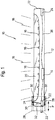
- Fig. 1 shows a lamp 10, which in the example of Fig. 1 is designed as a linear luminaire.
- the lamp 10 comprises a lamp base body 12, which houses a ballast 14.
- the ballast 14 converts electrical energy from the power grid in such a way that LED lighting means 16 can be operated with the ballast 14.
- the LED lighting means 16 emit light 18 through a translucent area 20 of the lighting base body 12.
- a connector in the form of a plug 22 is arranged displaceably in the lamp base body.
- the lamp base body 12 includes a fixed The counterpart connected to the lamp base body 12 in the form of a socket 24.
- the plug 22 and the socket 24 are electrically connected to the ballast 14 by means of cabling 26.
- the wiring 26 also includes through wiring between the plug 22 and the socket 24.
- a handling element in the form of a union sleeve 28 is attached around the lamp base body 12 on the outside of the lamp base body 12.
- the union sleeve 28 can be displaced along the longitudinal direction of the lamp base body 12 on the lamp base body 12, as is indicated by an arrow P.
- the union sleeve 28 can be displaced in such a way that the union sleeve 28 protrudes beyond the outer contour of the lamp base body 12, as in FIG Fig. 1 is indicated by dotted lines.
- the union sleeve 28 produces a sealed connection to the lamp base body 12.
- the union sleeve 28 comprises two sealing rings 30.
- Fig. 2 shows three lights 10, which are each arranged adjacent to one another on their end faces in order to form a light band 34.
- the plugs 22 are each in the extended position and engage in the socket 24 of the next lamp 10.
- an electrical plug connection 36 is realized in each case.
- Fig. 3 shows the light band 34 in an external view. It can be seen that the union sleeves 28 each cover and connect the ends of the lamp base body 12, so that a continuous light band structure is created.
- Fig. 4 shows the lamp base body 12, which in the example of Fig. 4 has a circular cross-section.
- the luminaire base body 12 is completely encircled by the union sleeve 28, the sealing ring 30 likewise producing a connection between the lamp base body 12 and the union sleeve 28 all the way around.
- Fig. 5 shows the same facts as Fig. 4 with the difference that the lamp base body 12 has a rectangular cross section there. Accordingly, at Fig. 5 the cross section of the union sleeve 28 is also rectangular.
- Fig. 6 shows an elongated recess 40 in the lamp base body 12.
- the coupling element 32 runs through the elongated recess 40.
- the elongated recess 40 is arranged in the end region of the lamp base body 12 in such a way that that the elongated recess 40 is always or at least covered by the coupling sleeve 28 when the plug is extended and / or lies in the sealed area 38. Penetration of, for example, moisture into the interior of the lamp base body 12 through the elongated recess 40 is prevented in this way.
- Fig. 7 shows the union sleeve 28 in a schematic side view.
- the union sleeve 28 comprises two sealing rings 30.
- the sealing rings 30 are each arranged in the area of the opposite ends of the union sleeve 28.
- the union sleeve 28 has a circumferential groove 42 between the sealing rings 30.
- the coupling element 32 is mounted in the circumferential groove 42, so that the coupling element 32 does not oppose a rotation of the union sleeve 28 around the luminaire base body 12.
- Fig. 8 finally shows a carriage 44 which is part of the coupling element 32.
- the slide 44 comprises two clips in the form of fastening arms 46 which are connected to further parts of the coupling element 32.
- the plug 22 is fastened on the slide 44, with plug contacts 48 protruding beyond the slide 44. The plug contacts 48 then establish the electrical plug connection 36 in the socket 24.
- the lamp 10 and thus its lamp base body 12 is attached adjacent to other lamps 10, for example on a ceiling.
- the union sleeve 28 of a light 10 has to be pushed in the direction of the closest adjacent light 10.
- the plug 22 is extended from the lamp base body 12 and pushed into the socket 24, whereby the electrical contact is made.
- a seal between the two lamps 10 connected in this way is also created with one and the same movement. The installation of the lamp 10 can thus be completed in a few simple steps.
Landscapes
- Engineering & Computer Science (AREA)
- General Engineering & Computer Science (AREA)
- Non-Portable Lighting Devices Or Systems Thereof (AREA)
- Arrangement Of Elements, Cooling, Sealing, Or The Like Of Lighting Devices (AREA)
Abstract
Description
- Die vorliegende Erfindung betrifft eine Leuchte, insbesondere eine Langfeldleuchte. Die Leuchte umfasst einen Leuchtengrundkörper, welcher elektrische Komponenten der Leuchte beherbergt.
- Langfeldleuchten werden häufig zu sogenannten Lichtbändern zusammengeschaltet, bei welchen eine Vielzahl von Leuchten direkt hintereinander angeordnet ist, um das Lichtband zu bilden. Solche Lichtbänder kommen beispielsweise in U-Bahnhöfen, Industrieanlagen oder allgemein in großen Gebäuden zum Einsatz.
- Üblicherweise erfolgt eine elektrische Kontaktierung der Leuchten mittels einer Verdrahtung, die für jede Leuchte einzeln manuell hergestellt wird. Das Herstellen der Verdrahtung, insbesondere bei bereits an z.B. einer Decke montierten Leuchten, ist dabei aufwendig und zeitintensiv.
- Es ist die der Erfindung zugrunde liegende Aufgabe, eine Leuchte anzugeben, die mit geringerem Aufwand montiert und elektrisch angeschlossen werden kann und sich insbesondere für die Montage in Lichtbändern eignet.
- Diese Aufgabe wird durch eine Leuchte gemäß Anspruch 1 gelöst.
- Die erfindungsgemäße Leuchte zeichnet sich dadurch aus, dass der Leuchtengrundkörper einen elektrischen Verbinder, beispielsweise einen Stecker, umfasst, wobei der Verbinder zwischen einer zurückgezogenen und einer ausgefahrenen Stellung bewegbar ist, wobei der Verbinder in der ausgefahrenen Stellung aus dem Leuchtengrundkörper herausragt. Die Leuchte umfasst ferner ein Handhabungselement, mittels welchem der Verbinder zwischen der zurückgezogenen und der ausgefahrenen Stellung bewegbar ist. Schließlich weist der Leuchtengrundkörper ein Gegenstück, beispielsweise eine Buchse, auf, das zum Herstellen einer elektrischen Steckverbindung mit einem den vorgenannten Verbinder entsprechenden weiteren Verbinder einer benachbart angeordneten weiteren Leuchte ausgebildet ist.
- Anders ausgedrückt umfasst die Leuchte einen Verbinder, der durch Betätigen des Handhabungselements ausgefahren werden kann. Der ausgefahrene Verbinder kann dann in das Gegenstück einer benachbart angeordneten weiteren Leuchte eingreifen und auf diese Weise eine elektrische Verbindung oder Steckverbindung zwischen den beiden Leuchten herstellen.
- Erfindungsgemäß entfällt damit der Verdrahtungsaufwand, da beispielsweise in einem Lichtband benachbarte Leuchten lediglich auf herkömmliche Art und Weise an ihrem Einsatzort befestigt werden müssen. Nach dem Anbringen bzw. Befestigen der Leuchten kann dann das Handhabungselement betätigt werden, wodurch der Verbinder ausfährt und die elektrische Verbindung mit dem Gegenstück der benachbarten Leuchte herstellt. Die Zeitdauer zur Herstellung der elektrischen Verbindung kann damit auf wenige Sekunden reduziert werden. Ebenfalls ist von Vorteil, dass die Herstellung der elektrischen Verbindung bevorzugt werkzeuglos erfolgen kann. Überdies wird z.B. auch das Risiko eines elektrischen Schlages oder von Verdrahtungsfehlern eliminiert.
- Über die elektrische Steckverbindung von Verbinder/Stecker und Gegenstück/Buchse wird bevorzugt sämtliche zum Betrieb der Leuchte erforderliche Energie übertragen. Ebenfalls ist es möglich, dass die Steckverbindung Datenleitungen umfasst und/oder eine Datenübertragung, z.B. von digitalen Daten, an die Leuchte ermöglicht.
- Insbesondere kann der Verbinder in der zurückgezogenen Stellung die Außenkontur der Leuchte nicht vergrößern und/oder in der zurückgezogenen Stellung vollständig in den Leuchtengrundkörper eingefahren sein. Durch die nicht vergrößerte Außenkontur kann die Leuchte auch ohne großen Aufwand in einem Mittelteil eines bereits bestehenden Lichtbandes eingesetzt werden, sodass die Leuchte dann bündig mit benachbarten Leuchten angeordnet ist. Dies wäre nicht möglich, wenn der Verbinder bereits während des Einbaus über die Außenkontur der Leuchte übersteht. Mit der erfindungsgemäßen Leuchte ist somit mit geringem Installationsaufwand auch der Austausch einer Leuchte in einem Lichtband möglich, ohne große Teile des Lichtbands zu demontieren, wie später noch ausgeführt wird.
- Die Leuchte ist bevorzugt eine Langfeldleuchte. Die Leuchte definiert durch ihre Länge eine Längsrichtung. Die Bewegung des Handhabungselements erfolgt bevorzugt hauptsächlich oder ausschließlich entlang dieser Längsrichtung. Auch der Verbinder bewegt sich zwischen der zurückgezogenen und der ausgefahrenen Stellung bevorzugt in der Längsrichtung. Schließlich kann auch das Gegenstück derart angeordnet sein, dass ein Einführen des Verbinders nur in der Längsrichtung möglich ist. Das Gegenstück ist bevorzugt über eine Gegenstück-Aussparung in dem Leuchtengrundkörper zugänglich. Insbesondere ist das Gegenstück an einer Innenwand des Leuchtengrundkörpers angebracht.
- Die Leuchte kann ein oder mehrere Leuchtmittel umfassen. Bei den Leuchtmitteln kann es sich insbesondere um eine Vielzahl von LEDs handeln. Die LEDs können beispielsweise in einer (geraden) Reihe entlang der Längsrichtung des Leuchtengrundkörpers in dem Leuchtengrundkörper angebracht sein.
- Vorteilhafte Weiterbildungen der Erfindung sind der Beschreibung, den Zeichnungen, sowie den abhängigen Ansprüchen zu entnehmen.
- Gemäß einer ersten vorteilhaften Ausführungsform ist das Handhabungselement außerhalb des Leuchtengrundkörpers angebracht. Durch das außerhalb angebrachte Handhabungselement ist dieses leicht zugänglich, sodass insbesondere eine manuelle Bedienung des Handhabungselements möglich wird, die dann zur Bewegung des Verbinders zwischen der zurückgezogenen und der ausgefahrenen Stellung führt. Das Handhabungselement kann insbesondere werkzeuglos bedient und/oder bewegt werden.
- Das Handhabungselement kann auf verschiedene Arten realisiert werden, wobei das Handhabungselement dazu dient, den Verbinder im eingebauten Zustand der Leuchte, das heißt wenn die Leuchte bereits an ihrem Einsatzort montiert ist, zu bewegen.
- Bevorzugt kann die Leuchte eine Durchgangsverdrahtung umfassen, die sich zwischen dem Verbinder und dem Gegenstück der Leuchte erstreckt und Verbinder und Gegenstück elektrisch kontaktiert. Aufgrund der Durchgangsverdrahtung kann mittels des Verbinders und des Gegenstücks nicht nur die Leuchte selbst mit elektrischer Energie versorgt werden, über den Verbinder und das Gegenstück kann dementsprechend auch die elektrische Energie für weitere Leuchten eines Lichtbands übertragen werden. Aus diesem Grund kann die Strombelastbarkeit des Verbinders und/oder des Gegenstücks für einen Strom ausgelegt sein, den mehr als 10, bevorzugt mehr als 50 und besonders bevorzugt mehr als 100 Leuchten gleichzeitig im Betrieb benötigen.
- Gemäß einer weiteren vorteilhaften Ausführungsform umfasst das Handhabungselement eine Überwurfmuffe, welche an einer Außenseite des Leuchtengrundkörpers verschiebbar gelagert ist und wobei eine Verschiebung der Überwurfmuffe ein Bewegen des Verbinders bewirkt. Die Überwurfmuffe kann in ihrer Form der Außenkontur der Leuchte bzw. der Außenkontur des Leuchtengrundkörpers angepasst sein. Überdies kann die Überwurfmuffe oder das Handhabungselement Griffmulden oder Erhöhungen zur besseren manuellen Bedienbarkeit umfassen.
- Die Überwurfmuffe kann beispielsweise direkt linear verschoben werden, beispielsweise in Längsrichtung der Leuchte. Alternativ oder zusätzlich kann die Verschiebung auch durch ein Drehen der Überwurfmuffe bewirkt oder erleichtert werden. Die Überwurfmuffe kann vollständig umlaufend um den Leuchtengrundkörper ausgebildet sein.
- Insbesondere umfasst die Leuchte genau eine Überwurfmuffe, die in nur einem Endbereich des insbesondere länglichen Leuchtengrundkörpers angeordnet ist. Der Endbereich kann verjüngt ausgebildet sein, sodass die Überwurfmuffe nicht auf die Außenkontur der Leuchte aufträgt und die Außenkontur der Leuchte somit einheitlich ist. Bevorzugt kann die Leuchte auf ihre gesamte Länge eine im Wesentlichen gleiche Höhe und Breite aufweisen.
- Das Handhabungselement bzw. die Überwurfmuffe können somit entlang des Leuchtengrundkörpers verschiebbar sein. An derjenigen Position, an welcher sich das Handhabungselement befindet, wenn der Verbinder in der zurückgezogenen Stellung ist, verlängert das Handhabungselement insbesondere nicht den Leuchtengrundkörper. Diese Position des Handhabungselements kann als zurückgezogene Position bezeichnet werden.
- Dadurch, dass das Handhabungselement in der zurückgezogenen Position nicht über den Leuchtengrundkörper übersteht, ist wiederum ein Einbau zwischen zwei bestehenden Leuchten eines Lichtbandes möglich.
- Gemäß einer weiteren vorteilhaften Ausführungsform steht das Handhabungselement nach dem Bewegen des Verbinders in die ausgefahrene Stellung derart über den Leuchtengrundkörper über, dass das Handhabungselement in der Lage ist, eine mechanische Verbindung zwischen der Leuchte und der benachbarten Leuchte herzustellen ("ausgefahrene Position des Handhabungselements"). Durch das Schieben des Handhabungselements bzw. der Überwurfmuffe in Richtung der benachbarten Leuchte wird somit einerseits der Verbinder ausgefahren um die elektrische Verbindung herzustellen. Andererseits steht die Überwurfmuffe in Richtung der benachbarten Leuchte über, sodass es zu einer mechanischen Kopplung der beiden Leuchten durch die Überwurfmuffe kommt.
- Gemäß einer weiteren vorteilhaften Ausführungsform umfasst das Handhabungselement Dichtelemente, welche zumindest dann eine abgedichtete Verbindung zwischen dem Leuchtengrundkörper und dem Handhabungselement einerseits und/oder zwischen dem Handhabungselement und der benachbarten Leuchte andererseits herstellen, wenn der Verbinder in der ausgefahrenen Stellung ist. Die abgedichtete Verbindung schützt bevorzugt die elektrische Steckverbindung vor beispielsweise Wasser, Staub, Feuchtigkeit und/oder Chemikalien. Die Leuchte kann sich dementsprechend für Feuchträume eignen und als Feuchtraumleuchte ausgebildet sein. Die Leuchte kann z.B. die Schutzart IP 65, IP 66, IP 67, IP 68 oder IP 69 erfüllen. Auch höhere Schutzarten sind möglich. Auch die abgedichtete Verbindung kann eine der vorgenannten Schutzarten erfüllen.
- Durch die abgedichtete Verbindung bzw. die Dichtelemente des Handhabungselements kann ein abgedichteter Verbindungsraum zwischen zwei benachbarten Leuchten geschaffen werden. In diesem Verbindungsraum liegt bevorzugt die elektrische Steckverbindung. Der Verbindungsraum wird insbesondere begrenzt durch eine erste abgedichtete Verbindung zwischen dem Handhabungselement und der Leuchte und einer zweiten abgedichteten Verbindung zwischen dem Handhabungselement und der benachbarten Leuchte.
- Die abgedichtete Verbindung kann beispielsweise über gleitende Dichtungen hergestellt werden, bei welcher zumindest oder genau eine Dichtung dauerhaft an dem Leuchtengrundkörper anliegt. Hierbei kann die abgedichtete Verbindung auch dann bestehen, wenn das Handhabungselement auf dem Leuchtengrundkörper verschoben wird.
- Durch die Betätigung des Handhabungselements kann somit mit einer einzigen Bewegung sowohl eine elektrische Verbindung zwischen den benachbarten Leuchten, als auch eine abgedichtete Verbindung geschaffen werden. Durch die wenigen notwendigen Handgriffe wird der Installationsaufwand deutlich reduziert. Zudem werden Fehlerquellen eliminiert, da sowohl die elektrische Verbindung als auch die abgedichtete Verbindung quasi automatisch hergestellt werden.
- Die Dichtelemente können beispielsweise zwei umlaufende Dichtringe umfassen. Nach dem Herstellen der abgedichteten Verbindung kann ein Dichtring an der Leuchte und der zweite Dichtring an der benachbarten Leuchte anliegen. Das Handhabungselement kann dann etwa mittig zwischen beiden Leuchten liegen.
- Alternativ oder zusätzlich kann das Handhabungselement bzw. die Überwurfmuffe ein Spannelement aufweisen, beispielsweise einen Spannhebel oder eine Spannschraube. Das Spannelement kann in der ausgefahrenen Stellung des Verbinders bzw. des Handhabungselements betätigt werden, um die Dichtung herzustellen, indem das Handhabungselement gegen den Leuchtengrundkörper gepresst wird. Hierdurch kann gleichzeitig eine Arretierung gegen unbeabsichtigtes Rückschieben des Handhabungselements erfolgen.
- Allgemein kann die Leuchte auch eine Sicherungseinrichtung gegen ein unbeabsichtigtes Betätigen bzw. Verschieben des Handhabungselements umfassen.
- Der Leuchtengrundkörper kann gemäß einer Ausführungsform ein Außengewinde umfassen, wohingegen die Überwurfmuffe ein mit dem Außengewinde in Eingriff stehendes Innengewinde aufweist, sodass durch eine Drehung der Überwurfmuffe eine Verschiebung derselben bewirkt werden kann. Insbesondere ist auch eine Drehung der Überwurfmuffe mit anschließender Verrastung der Überwurfmuffe möglich (z.B. nach Art eines Bajonettverschlusses).
- Alternativ kann der Leuchtengrundkörper auch eine Führungsnut aufweisen, um ein Verdrehen der Überwurfmuffe zu verhindern.
- Insbesondere erfolgt im Bereich des Handhabungselements, bevorzugt im Bereich der ausgefahrenen Position des Handhabungselements, keine Abstrahlung von Licht. Insbesondere befinden sich im Bereich des Handhabungselements in der ausgefahrenen Position keine Leuchtmittel.
- Gemäß einer weiteren vorteilhaften Ausführungsform ist das Handhabungselement mittels eines Koppelelements mechanisch mit dem Verbinder verbunden, wobei sich das Koppelelement durch eine, bevorzugt längliche, Aussparung des Leuchtengrundkörpers hindurch erstreckt. Das Koppelelement kann dazu dienen, eine Bewegung des Handhabungselements auf den Verbinder zu übertragen, um auf diese Weise den Verbinder zu bewegen. Das Koppelelement kann beispielsweise gleitend in einer Nut des Handhabungselements geführt sein. Die Nut kann umlaufend um den Leuchtengrundkörper ausgebildet sein. Auf diese Weise kann das Handhabungselement um den Leuchtengrundkörper gedreht werden, wobei die mechanische Verbindung zu dem Koppelelement erhalten bleibt.
- Gemäß einer weiteren vorteilhaften Ausführungsform umfasst das Koppelelement einen bewegbaren Schlitten, auf welchem der Verbinder befestigt ist. Der Schlitten kann eine Befestigungsfläche für den Verbinder aufweisen. Der Schlitten kann zudem zwei Befestigungsklipse auf gegenüberliegenden Seiten der Befestigungsfläche umfassen, wobei die Befestigungsklipse die weiteren Teile des Koppelelements mit dem Schlitten verbinden. Der Schlitten kann beispielsweise auf einer Führungsfläche oder in einer Führungsnut gleiten, um so den Verbinder zwischen der ausgefahrenen und der zurückgezogenen Stellung zu bewegen.
- Die oben genannte längliche Aussparung kann dementsprechend eine Länge aufweisen, die etwa der Weglänge entspricht, die der Verbinder bei seiner Bewegung zwischen der zurückgezogenen und der ausgefahrenen Stellung zurücklegt.
- Gemäß einer weiteren vorteilhaften Ausführungsform umfasst der Leuchtengrundkörper zwei Endstücke, welche gegenüberliegende stirnseitige Enden des Leuchtengrundkörpers bilden. Dabei sind das Gegenstück und der Verbinder in verschiedenen, das heißt gegenüberliegenden, stirnseitigen Enden angeordnet. Bei der Leuchte handelt es sich insbesondere um eine Langfeldleuchte.
- Bei einer Landfeldleuchte ist die Längserstreckung des Leuchtengrundkörpers deutlich länger als dessen Breite und/oder Höhe.
- Anders ausgedrückt ist der Verbinder in einem Ende der Leuchte und das Gegenstück in dem gegenüberliegenden Ende der Leuchte angeordnet. Ganz allgemein gesprochen liegen sich Gegenstück und Verbinder gegenüber, um eine aneinandergereihte Montage mehrerer Leuchten zu ermöglichen.
- Bevorzugt ist das Gegenstück ortsfest, das heißt gegenüber dem Leuchtengrundkörper nicht bewegbar.
- Weiter bevorzugt kann die von Verbinder und Gegenstück geschaffene Steckverbindung abgedichtet sein, beispielsweise nach der Schutzart IP68 oder einer der vorgenannten Schutzarten.
- Gemäß einer weiteren vorteilhaften Ausführungsform umfasst der Leuchtengrundkörper einen transluzenten Bereich, in welchem die Leuchte Licht abstrahlt, wobei sich der transluzente Bereich bevorzugt bis zu dem Handhabungselement erstreckt. Weiter bevorzugt erstreckt sich der transluzente Bereich bis zu dem Handhabungselement in seiner ausgefahrenen Stellung. Auf diese Weise werden dunkle Bereiche zwischen zwei Leuchten bzw. zwischen zwei transluzenten Bereichen benachbarter Leuchten minimiert.
- Alternativ ist es möglich, dass das Handhabungselement aus einem transluzenten oder transparenten Material geformt ist, sodass auch im Bereich des Handhabungselements eine Lichtemission erfolgt. Das Handhabungselement kann hierzu beispielsweise aus transluzentem Kunststoff gefertigt werden und beispielsweise transparente Dichtungen, z.B. aus Silikon, umfassen. Der transluzente Bereich des Leuchtengrundkörpers kann sich dann bis unter das Handhabungselement erstrecken. Hierdurch kann dann der Eindruck eines nahezu unterbrechungsfreien Lichtbandes geschaffen werden.
- Alternativ kann der Leuchtengrundkörper auch keinen transluzenten Bereich aufweisen. Die Lichtemission der Leuchte kann dann von einem separaten Leuchtmittelgehäuse ausgehen, wobei das Leuchtmittelgehäuse insbesondere am Leuchtengrundkörper befestigt ist.
- Gemäß einer weiteren vorteilhaften Ausführungsform weist der Leuchtengrundkörper einen rechteckigen oder kreisförmigen oder elliptischen Querschnitt auf. Das Handhabungselement kann einen entsprechend angepassten Querschnitt besitzen und dementsprechend ebenfalls rechteckig, kreisförmig oder elliptisch sein. Der Querschnitt des Leuchtengrundkörpers und/oder des Handhabungselements ist bevorzugt über deren jeweilige Länge annähernd gleich.
- Die Erfindung betrifft weiterhin ein System umfassend zumindest zwei Leuchten der vorstehend erläuterten Art. Bei dem System stellt der Verbinder einer ersten Leuchte eine elektrische Verbindung mit dem Gegenstück einer zweiten Leuchte her, wobei bevorzugt das Handhabungselement der ersten Leuchte mechanisch mit der ersten und zweiten Leuchte verbunden ist (oder zumindest an beiden Leuchten anliegt), wenn die elektrische Verbindung hergestellt ist. Das Handhabungselement dichtet bevorzugt gegenüber dem Leuchtengrundkörper der ersten und zweiten Leuchte ab.
- Das System kann auch mehr als zwei Leuchten umfassen, beispielsweise mehr als 10, mehr als 20 oder mehr als 100 Leuchten. Jeweils der Verbinder einer Leuchte ist dann elektrisch mit dem Gegenstück der nächsten Leuchte verbunden. Auch das Handhabungselement einer Leuchte stellt dann jeweils auch mechanisch eine abgedichtete Verbindung zwischen der Leuchte und der nächsten Leuchte her. Auf diese Weise wird ein Lichtband geschaffen. Die Leuchten eines Lichtbandes sind bevorzugt jeweils baugleich ausgeführt.
- Die Erfindung betrifft auch ein Verfahren zur Montage einer Leuchte der voranstehend erläuterten Art in einem Lichtband, bei welchem
- die Leuchte benachbart zu einer weiteren Leuchte befestigt wird,
- das Handhabungselement betätigt wird, um den Verbinder der Leuchte von der zurückgezogenen Stellung in die ausgefahrene Stellung zu bewegen, wodurch der Verbinder das Gegenstück der weiteren Leuchte kontaktiert und eine elektrische Verbindung herstellt.
- Wie vorstehend bereits erläutert, wird der Aufwand zur Schaffung der elektrischen Energieversorgung durch die wenigen notwendigen Handgriffe zum Ausfahren des Verbinders drastisch reduziert.
- Insbesondere ist es auch möglich, die Leuchte zwischen zwei benachbarte Leuchten zu montieren. Die beiden stirnseitigen Enden der Leuchte liegen dann angrenzend oder benachbart zu einem stirnseitigen Ende jeweils einer der benachbarten Leuchten. Durch Betätigung des Handhabungselements der neu eingesetzten Leuchte wird dann die elektrische Verbindung mit der ersten benachbarten Leuchte geschaffen. Durch Betätigung des Handhabungselements der zweiten benachbarten Leuchte fährt der Verbinder der zweiten benachbarten Leuchte in das Gegenstück der neu eingesetzten Leuchte ein, wodurch auch hier die elektrische Verbindung geschaffen wird, sodass für das Lichtband eine durchgehende elektrische Energieversorgung besteht.
- Die hierin beschriebene Leuchte bietet nicht nur Vorteile beim Einsetzen einer neuen Leuchte in ein Lichtband oder beim Aufbau eines neuen Lichtbandes. Auch beim Ausbau oder beim Austausch einer Leuchte eines bereits bestehenden Lichtbandes bestehen Vorteile.
- Dementsprechend umfasst die Erfindung auch ein Verfahren zur Demontage, bei welchem die Handhabungselemente zweier benachbarter Leuchten eines Lichtbandes betätigt werden, um jeweils den Verbinder in die zurückgezogene Stellung zu bewegen. Zumindest eine der Leuchten ist dann nicht mehr mittels der elektrischen Steckverbindungen und bevorzugt auch nicht mehr mittels der mechanischen Verbindungen durch die Handhabungselemente mit den benachbarten Leuchten verbunden. Diese Leuchte kann dann aus dem Lichtband ausgebaut werden, ohne dass ein großer Aufwand zur Demontage weiterer Teile des Lichtbands anfällt.
- Die zu der erfindungsgemäßen Leuchte vorgebrachten Erläuterungen gelten für das erfindungsgemäße System und die erfindungsgemäßen Verfahren entsprechend, dies gilt insbesondere hinsichtlich Vorteilen und bevorzugten Ausführungsformen.
- Nachfolgend wird die Erfindung rein beispielhaft unter Bezugnahme auf die Zeichnungen beschrieben. Es zeigen:
- Fig. 1
- eine Langfeldleuchte in schematischer Schnittansicht;
- Fig. 2
- ein Lichtband mit mehreren Landfeldleuchten in schematischer Schnittansicht;
- Fig. 3
- das Lichtband von
Fig. 2 in einer schematischen Außenansicht; - Fig. 4 und Fig. 5
- jeweils eine Querschnittsansicht eines Leuchtengrundkörpers mit aufgeschobenem Handhabungselement;
- Fig. 6
- eine Draufsicht auf eine Aussparung in dem Leuchtengrundkörper;
- Fig. 7
- eine schematische Ansicht eines Handhabungselements; und
- Fig. 8
- einen Schlitten mit darauf befestigtem Stecker.
-
Fig. 1 zeigt eine Leuchte 10, die im Beispiel derFig. 1 als Langfeldleuchte ausgebildet ist. Die Leuchte 10 umfasst einen Leuchtengrundkörper 12, welcher ein Vorschaltgerät 14 beherbergt. Das Vorschaltgerät 14 wandelt elektrische Energie des Stromnetzes derart um, dass LED-Leuchtmittel 16 mit dem Vorschaltgerät 14 betrieben werden können. - Die LED-Leuchtmittel 16 emittieren Licht 18 durch einen transluzenten Bereich 20 des Leuchtengrundkörpers 12.
- In dem Leuchtengrundkörper ist ein Verbinder in Form eines Steckers 22 verschieblich angeordnet. Überdies umfasst der Leuchtengrundkörper 12 ein fest mit dem Leuchtengrundkörper 12 verbundenes Gegenstück in Form einer Buchse 24. Der Stecker 22 und die Buchse 24 sind mittels einer Verkabelung 26 mit dem Vorschaltgerät 14 elektrisch verbunden. Die Verkabelung 26 umfasst auch eine Durchgangsverdrahtung zwischen dem Stecker 22 und der Buchse 24.
- In einem Endbereich des Leuchtengrundkörpers 12, in welchem der Stecker 22 angeordnet ist, ist ein Handhabungselement in Form einer Überwurfmuffe 28 umlaufend um den Leuchtengrundkörper 12 an der Außenseite des Leuchtengrundkörpers 12 angebracht. Die Überwurfmuffe 28 ist entlang der Längsrichtung des Leuchtengrundkörpers 12 auf dem Leuchtengrundkörper 12 verschiebbar, wie dies durch einen Pfeil P angedeutet wird.
- Die Überwurfmuffe 28 kann derart verschoben werden, dass die Überwurfmuffe 28 über die Außenkontur des Leuchtengrundkörpers 12 hinausragt, wie in
Fig. 1 durch gepunktete Linien angedeutet ist. Die Überwurfmuffe 28 stellt eine abgedichtete Verbindung zum Leuchtengrundkörper 12 her. Zu diesem Zweck umfasst die Überwurfmuffe 28 zwei Dichtringe 30. - Die Überwurfmuffe 28 ist mittels eines Koppelelements 32 mit dem Stecker 22 derart verbunden, dass eine Verschiebung der Überwurfmuffe 28 zu einer entsprechenden Verschiebung bzw. Bewegung des Steckers 22 führt. Der Stecker 22 kann durch die Überwurfmuffe 28 somit von einer zurückgezogenen Stellung, die in der Figur mit durchgezogenen Linien gezeigt ist, in eine ausgefahrene Stellung überführt werden. Die ausgefahrene Stellung ist in der
Fig. 1 gepunktet angedeutet. In der ausgefahrenen Stellung ragt der Stecker 22 aus dem Leuchtengrundkörper 12 hervor und kann dementsprechend in eine Buchse 24 einer benachbart angeordneten Leuchte 10 eingeführt werden, wie später noch genauer dargestellt. Es versteht sich, dass Stecker 22 und Buchse 24 auch vertauscht angeordnet sein können, d.h. dass die Buchse 24 bewegt wird, wohingegen der Stecker 22 fest montiert ist. -
Fig. 2 zeigt drei Leuchten 10, welche jeweils an ihren Stirnseiten benachbart zueinander angeordnet sind, um ein Lichtband 34 zu bilden. WieFig. 2 zu entnehmen ist, sind die Stecker 22 jeweils in der ausgefahrenen Stellung und greifen in die Buchse 24 der jeweils nächsten Leuchte 10 ein. Durch den Eingriff der Stecker 22 in die Buchsen 24 wird jeweils eine elektrische Steckverbindung 36 verwirklicht. - Um die Stecker 22 in die ausgefahrene Stellung zu bewegen, wurden jeweils die Überwurfmuffen 28 von einer Leuchte 10 teilweise auf die nächste Leuchte 10 aufgeschoben, sodass jeweils ein Dichtring 30 an einer ersten Leuchte 10 und ein zweiter Dichtring 30 an einer zweiten Leuchte 10 anliegt. Auf diese Weise wird ein abgedichteter Bereich 38 zwischen den Leuchten 10 geschaffen. Die elektrische Steckverbindung 36 ist damit gegen schädliche Umwelteinflüsse geschützt.
-
Fig. 3 zeigt das Lichtband 34 in einer Außenansicht. Es ist zu erkennen, dass die Überwurfmuffen 28 jeweils die Enden der Leuchtengrundkörper 12 bedecken und verbinden, sodass eine durchgehende Lichtband-Struktur entsteht. -
Fig. 4 zeigt den Leuchtengrundkörper 12, welcher im Beispiel derFig. 4 einen kreisförmigen Querschnitt aufweist. Der Leuchtengrundkörper 12 ist vollständig umlaufend von der Überwurfmuffe 28 umgeben, wobei der Dichtring 30 ebenfalls vollständig umlaufend eine Verbindung zwischen dem Leuchtengrundkörper 12 und der Überwurfmuffe 28 herstellt.Fig. 5 zeigt denselben Sachverhalt wieFig. 4 mit dem Unterschied, dass der Leuchtengrundkörper 12 dort einen rechteckigen Querschnitt aufweist. Dementsprechend ist beiFig. 5 auch der Querschnitt der Überwurfmuffe 28 rechteckig. -
Fig. 6 zeigt eine längliche Aussparung 40 in dem Leuchtengrundkörper 12. Durch die längliche Aussparung 40 verläuft das Koppelelement 32 hindurch. Die längliche Aussparung 40 ist derart im Endbereich des Leuchtengrundkörpers 12 angeordnet, dass die längliche Aussparung 40 immer oder zumindest bei ausgefahrenem Stecker durch die Überwurfmuffe 28 verdeckt wird und/oder in dem abgedichteten Bereich 38 liegt. Ein Eindringen beispielsweise von Feuchtigkeit in das Innere des Leuchtengrundkörpers 12 durch die längliche Aussparung 40 wird auf diese Weise verhindert. -
Fig. 7 zeigt die Überwurfmuffe 28 in einer schematischen Seitenansicht. Wie bereits erwähnt umfasst die Überwurfmuffe 28 zwei Dichtringe 30. Die Dichtringe 30 sind jeweils im Bereich der gegenüberliegenden Enden der Überwurfmuffe 28 angeordnet. Zwischen den Dichtringen 30 weist die Überwurfmuffe 28 eine umlaufende Nut 42 auf. In der umlaufenden Nut 42 ist das Koppelelement 32 gelagert, sodass das Koppelelement 32 einer Drehung der Überwurfmuffe 28 um den Leuchtengrundkörper 12 herum nicht entgegensteht. -
Fig. 8 zeigt schließlich einen Schlitten 44, welcher Teil des Koppelelements 32 ist. Der Schlitten 44 umfasst zwei Klipse in Form von Befestigungsarmen 46, welche mit weiteren Teilen des Koppelelements 32 verbunden sind. Auf dem Schlitten 44 ist der Stecker 22 befestigt, wobei über den Schlitten 44 Steckerkontakte 48 hinausragen. Die Steckerkontakte 48 stellen dann in der Buchse 24 die elektrische Steckverbindung 36 her. - Beim Einsatz der Leuchte 10 wird die Leuchte 10 und damit deren Leuchtengrundkörper 12 benachbart zu weiteren Leuchten 10 z.B. an einer Decke befestigt. Um nun eine elektrische Kontaktierung zwischen den Leuchten 10 zu schaffen, muss jeweils nur die Überwurfmuffe 28 einer Leuchte 10 in Richtung der nächstliegenden benachbarten Leuchte 10 geschoben werden. Hierdurch wird der Stecker 22 aus dem Leuchtengrundkörper 12 ausgefahren und in die Buchse 24 eingeschoben, wodurch die elektrische Kontaktierung realisiert wird. Durch die Bewegung der Überwurfmuffe 28 wird mit ein und derselben Bewegung außerdem eine Abdichtung zwischen den beiden derart verbundenen Leuchten 10 geschaffen. Mit wenigen Handgriffen kann somit die Installation der Leuchte 10 abgeschlossen werden.
-
- 10
- Leuchte
- 12
- Leuchtengrundkörper
- 14
- Vorschaltgerät
- 16
- LED-Leuchtmittel
- 18
- Licht
- 20
- transluzenter Bereich
- 22
- Stecker
- 24
- Buchse
- 26
- Verkabelung
- 28
- Überwurfmuffe
- 30
- Dichtring
- 32
- Koppelelement
- 34
- Lichtband
- 36
- elektrische Steckverbindung
- 38
- abgedichteter Bereich
- 40
- längliche Aussparung
- 42
- Umlaufende Nut
- 44
- Schlitten
- 46
- Befestigungsarm
- 48
- Steckerkontakt
- P
- Pfeil in Längsrichtung
Claims (12)
- Leuchte (10), insbesondere Langfeldleuchte, mit
einem Leuchtengrundkörper (12), welcher elektrische Komponenten (14, 26) der Leuchte (10) beherbergt,
dadurch gekennzeichnet, dass
der Leuchtengrundkörper (12) einen Verbinder (22), beispielsweise einen Stecker, umfasst, wobei der Verbinder (22) zwischen einer zurückgezogenen und einer ausgefahrenen Stellung bewegbar ist, wobei der Verbinder (22) in der ausgefahrenen Stellung aus dem Leuchtengrundkörper (12) herausragt, wobei die Leuchte (10) ein Handhabungselement (28) umfasst, mit welchem der Verbinder (22) zwischen der zurückgezogenen und der ausgefahrenen Stellung bewegbar ist, und
der Leuchtengrundkörper (12) ein Gegenstück (24), beispielsweise eine Buchse, aufweist, das zum Herstellen einer elektrischen Steckverbindung (36) mit einem dem vorgenannten Verbinder (22) entsprechenden weiteren Verbinder (22) einer benachbart angeordneten weiteren Leuchte (10) ausgebildet ist. - Leuchte (10) nach Anspruch 1,
wobei das Handhabungselement (28) außerhalb des Leuchtengrundkörpers (12) angebracht ist. - Leuchte (10) nach Anspruch 1 oder 2,
wobei das Handhabungselement (28) eine Überwurfmuffe umfasst, welche an einer Außenseite des Leuchtengrundkörpers (12) verschiebbar gelagert ist und wobei eine Verschiebung der Überwurfmuffe ein Bewegen des Verbinders (22) bewirkt. - Leuchte (10) nach zumindest einem der vorstehenden Ansprüche,
wobei das Handhabungselement (28) nach dem Bewegen des Verbinders (22) in die ausgefahrene Stellung derart über den Leuchtengrundkörper (12) übersteht, dass das Handhabungselement (28) in der Lage ist, eine mechanische Verbindung zwischen der Leuchte (10) und der benachbarten Leuchte (10) herzustellen. - Leuchte (10) nach zumindest einem der vorstehenden Ansprüche,
wobei das Handhabungselement (28) Dichtelemente (30) umfasst, welche zumindest dann eine abgedichtete Verbindung zwischen dem Leuchtengrundkörper (12) und dem Handhabungselement (28) einerseits und/oder zwischen dem Handhabungselement (28) und der benachbarten Leuchte (10) andererseits herstellen, wenn der Verbinder (22) in der ausgefahrenen Stellung ist. - Leuchte (10) nach zumindest einem der vorstehenden Ansprüche,
wobei das Handhabungselement (28) mittels eines Koppelelements (32) mechanisch mit dem Verbinder (22) verbunden ist, wobei sich das Koppelelement (32) durch eine längliche Aussparung (40) des Leuchtengrundkörpers (12) hindurch erstreckt. - Leuchte (10) nach Anspruch 6,
wobei das Koppelelement (32) einen bewegbaren Schlitten (44) umfasst, auf welchem der Verbinder (22) befestigt ist. - Leuchte (10) nach zumindest einem der vorstehenden Ansprüche,
wobei der Leuchtengrundkörper (12) zwei Endstücke umfasst, welche gegenüberliegende stirnseitige Enden des Leuchtengrundkörpers (12) bilden,
wobei das Gegenstück (24) und der Verbinder (22) in verschiedenen stirnseitigen Enden angeordnet sind. - Leuchte (10) nach zumindest einem der vorstehenden Ansprüche,
wobei der Leuchtengrundkörper (12) einen transluzenten Bereich (20) aufweist, in welchem die Leuchte (10) Licht (18) abstrahlt, wobei sich der transluzente Bereich (20) bevorzugt bis zu dem Handhabungselement (28) erstreckt. - Leuchte (10) nach zumindest einem der vorstehenden Ansprüche,
wobei der Leuchtengrundkörper (12) einen rechteckigen oder kreisförmigen oder elliptischen Querschnitt aufweist. - System umfassend zumindest zwei Leuchten (10) gemäß einem der vorstehenden Ansprüche, wobei
der Verbinder (22) einer ersten Leuchte (10) eine elektrische Verbindung mit dem Gegenstück (24) einer zweiten Leuchte (10) herstellt, wobei das Handhabungselement (28) der ersten Leuchte (10) mechanisch mit der ersten und der zweiten Leuchte (10) verbunden ist. - Verfahren zur Montage einer Leuchte (10) gemäß einem der Ansprüche 1 bis 10 in einem Lichtband (34), bei welchem- die Leuchte (10) benachbart zu einer weiteren Leuchte (10) befestigt wird,- das Handhabungselement (28) betätigt wird, um den Verbinder (22) der Leuchte (10) von der zurückgezogenen Stellung in die ausgefahrene Stellung zu bewegen, wodurch der Verbinder (22) das Gegenstück (24) der weiteren Leuchte (10) kontaktiert und eine elektrische Verbindung herstellt.
Applications Claiming Priority (1)
| Application Number | Priority Date | Filing Date | Title |
|---|---|---|---|
| DE102019113538.9A DE102019113538A1 (de) | 2019-05-21 | 2019-05-21 | Leuchte |
Publications (2)
| Publication Number | Publication Date |
|---|---|
| EP3742043A1 true EP3742043A1 (de) | 2020-11-25 |
| EP3742043B1 EP3742043B1 (de) | 2022-11-09 |
Family
ID=70779470
Family Applications (1)
| Application Number | Title | Priority Date | Filing Date |
|---|---|---|---|
| EP20175386.0A Active EP3742043B1 (de) | 2019-05-21 | 2020-05-19 | Leuchte |
Country Status (2)
| Country | Link |
|---|---|
| EP (1) | EP3742043B1 (de) |
| DE (1) | DE102019113538A1 (de) |
Citations (4)
| Publication number | Priority date | Publication date | Assignee | Title |
|---|---|---|---|---|
| FR1365013A (fr) * | 1963-07-31 | 1964-06-26 | Philips Nv | Appareil d'éclairage pour source lumineuse de forme allongée |
| US7331687B1 (en) * | 2006-10-12 | 2008-02-19 | Averd Co., Ltd. | Fluorescent lamp |
| DE102008016196A1 (de) * | 2008-03-27 | 2009-10-01 | Hadler Gmbh | Gehäuse zur Aufnahme eines Leuchtmittels |
| CN204240149U (zh) * | 2014-11-20 | 2015-04-01 | 深圳市凯信光电有限公司 | 一种led灯条 |
Family Cites Families (4)
| Publication number | Priority date | Publication date | Assignee | Title |
|---|---|---|---|---|
| DE2606038A1 (de) * | 1976-02-14 | 1977-08-18 | Hermann Abke | Gefuehrte, verschiebbare, elektrische kontakteinheit |
| US7959445B1 (en) * | 2009-08-28 | 2011-06-14 | Tyco Electronics Corporation | Board-to-board connector system |
| CN105333363A (zh) * | 2014-07-17 | 2016-02-17 | 欧司朗有限公司 | 照明单元和包括该照明单元的照明装置 |
| DE102017111878B4 (de) * | 2017-05-31 | 2019-02-21 | HARTING Electronics GmbH | LED-Panel mit Basisplatte |
-
2019
- 2019-05-21 DE DE102019113538.9A patent/DE102019113538A1/de not_active Withdrawn
-
2020
- 2020-05-19 EP EP20175386.0A patent/EP3742043B1/de active Active
Patent Citations (4)
| Publication number | Priority date | Publication date | Assignee | Title |
|---|---|---|---|---|
| FR1365013A (fr) * | 1963-07-31 | 1964-06-26 | Philips Nv | Appareil d'éclairage pour source lumineuse de forme allongée |
| US7331687B1 (en) * | 2006-10-12 | 2008-02-19 | Averd Co., Ltd. | Fluorescent lamp |
| DE102008016196A1 (de) * | 2008-03-27 | 2009-10-01 | Hadler Gmbh | Gehäuse zur Aufnahme eines Leuchtmittels |
| CN204240149U (zh) * | 2014-11-20 | 2015-04-01 | 深圳市凯信光电有限公司 | 一种led灯条 |
Also Published As
| Publication number | Publication date |
|---|---|
| EP3742043B1 (de) | 2022-11-09 |
| DE102019113538A1 (de) | 2020-11-26 |
Similar Documents
| Publication | Publication Date | Title |
|---|---|---|
| EP1142070B1 (de) | Elektrische verbindungsvorrichtung zum kontaktieren von leiteradern | |
| DE102013113429B3 (de) | Betätigungsvorrichtung für ein explosionsgeschütztes Gehäuse | |
| DE19513983A1 (de) | Signalsäule | |
| DE10025646A1 (de) | Stromschienensystem | |
| DE4418004A1 (de) | Elektrische Verbindung, insbesondere für Kraftfahrzeuge | |
| DE69606700T2 (de) | Lampenfassung zum hinein-/herausdrücken | |
| EP2264363B1 (de) | Leuchte, Endkappe und Lichtband | |
| EP1475565B1 (de) | Leuchtenanordnung | |
| EP2896098A1 (de) | Hülsendichtung | |
| EP2650595B1 (de) | Lichtband mit Leuchte | |
| EP4270683A1 (de) | Schienenprofil für eine profilleuchte oder für ein schienenleuchtensystem | |
| EP4273446A1 (de) | Befestigungseinrichtung zum befestigen einer leuchtbaugruppe sowie beleuchtungsanordnung mit mindestens einer derartigen befestigungseinrichtung | |
| EP3742043B1 (de) | Leuchte | |
| DE19719708A1 (de) | Sockel für eine Entladungslampe | |
| DE102008016196A1 (de) | Gehäuse zur Aufnahme eines Leuchtmittels | |
| DE2829721C3 (de) | Mosaikbaustein für Schalt- und Meldewarten | |
| DE202016004265U1 (de) | Verbindungselement und Leuchtenanordnung | |
| DE3620105C1 (en) | Electrical contact switch | |
| DE102021212616A1 (de) | Leuchte mit Tragprofil, Stromführungsschiene und Stecker | |
| DE10204738A1 (de) | Anschlusseinrichtung, Anschlusstück und Kontaktklammer für eine Fluidleitung | |
| DE102018131996B4 (de) | Leuchte und zu deren Realisierung vorgesehenes System und Verfahren | |
| EP0762563A2 (de) | Explosionsgeschützte Lampenfassung mit wahlweise zu öffnenden und zu schliessenden Kontaktmitteln | |
| DE102012107907A1 (de) | Leuchtenmodul und Verfahren zu dessen Montage | |
| DE2550026A1 (de) | Schalter | |
| DE1490808C3 (de) | Elektrische Steckverbindung |
Legal Events
| Date | Code | Title | Description |
|---|---|---|---|
| PUAI | Public reference made under article 153(3) epc to a published international application that has entered the european phase |
Free format text: ORIGINAL CODE: 0009012 |
|
| STAA | Information on the status of an ep patent application or granted ep patent |
Free format text: STATUS: THE APPLICATION HAS BEEN PUBLISHED |
|
| AK | Designated contracting states |
Kind code of ref document: A1 Designated state(s): AL AT BE BG CH CY CZ DE DK EE ES FI FR GB GR HR HU IE IS IT LI LT LU LV MC MK MT NL NO PL PT RO RS SE SI SK SM TR |
|
| AX | Request for extension of the european patent |
Extension state: BA ME |
|
| STAA | Information on the status of an ep patent application or granted ep patent |
Free format text: STATUS: REQUEST FOR EXAMINATION WAS MADE |
|
| 17P | Request for examination filed |
Effective date: 20210525 |
|
| RBV | Designated contracting states (corrected) |
Designated state(s): AL AT BE BG CH CY CZ DE DK EE ES FI FR GB GR HR HU IE IS IT LI LT LU LV MC MK MT NL NO PL PT RO RS SE SI SK SM TR |
|
| GRAP | Despatch of communication of intention to grant a patent |
Free format text: ORIGINAL CODE: EPIDOSNIGR1 |
|
| STAA | Information on the status of an ep patent application or granted ep patent |
Free format text: STATUS: GRANT OF PATENT IS INTENDED |
|
| INTG | Intention to grant announced |
Effective date: 20220523 |
|
| GRAS | Grant fee paid |
Free format text: ORIGINAL CODE: EPIDOSNIGR3 |
|
| GRAA | (expected) grant |
Free format text: ORIGINAL CODE: 0009210 |
|
| STAA | Information on the status of an ep patent application or granted ep patent |
Free format text: STATUS: THE PATENT HAS BEEN GRANTED |
|
| AK | Designated contracting states |
Kind code of ref document: B1 Designated state(s): AL AT BE BG CH CY CZ DE DK EE ES FI FR GB GR HR HU IE IS IT LI LT LU LV MC MK MT NL NO PL PT RO RS SE SI SK SM TR |
|
| REG | Reference to a national code |
Ref country code: GB Ref legal event code: FG4D Free format text: NOT ENGLISH |
|
| REG | Reference to a national code |
Ref country code: CH Ref legal event code: EP Ref country code: AT Ref legal event code: REF Ref document number: 1530586 Country of ref document: AT Kind code of ref document: T Effective date: 20221115 |
|
| REG | Reference to a national code |
Ref country code: DE Ref legal event code: R096 Ref document number: 502020001947 Country of ref document: DE |
|
| REG | Reference to a national code |
Ref country code: IE Ref legal event code: FG4D Free format text: LANGUAGE OF EP DOCUMENT: GERMAN |
|
| REG | Reference to a national code |
Ref country code: LT Ref legal event code: MG9D |
|
| REG | Reference to a national code |
Ref country code: NL Ref legal event code: MP Effective date: 20221109 |
|
| PG25 | Lapsed in a contracting state [announced via postgrant information from national office to epo] |
Ref country code: SE Free format text: LAPSE BECAUSE OF FAILURE TO SUBMIT A TRANSLATION OF THE DESCRIPTION OR TO PAY THE FEE WITHIN THE PRESCRIBED TIME-LIMIT Effective date: 20221109 Ref country code: PT Free format text: LAPSE BECAUSE OF FAILURE TO SUBMIT A TRANSLATION OF THE DESCRIPTION OR TO PAY THE FEE WITHIN THE PRESCRIBED TIME-LIMIT Effective date: 20230309 Ref country code: NO Free format text: LAPSE BECAUSE OF FAILURE TO SUBMIT A TRANSLATION OF THE DESCRIPTION OR TO PAY THE FEE WITHIN THE PRESCRIBED TIME-LIMIT Effective date: 20230209 Ref country code: LT Free format text: LAPSE BECAUSE OF FAILURE TO SUBMIT A TRANSLATION OF THE DESCRIPTION OR TO PAY THE FEE WITHIN THE PRESCRIBED TIME-LIMIT Effective date: 20221109 Ref country code: FI Free format text: LAPSE BECAUSE OF FAILURE TO SUBMIT A TRANSLATION OF THE DESCRIPTION OR TO PAY THE FEE WITHIN THE PRESCRIBED TIME-LIMIT Effective date: 20221109 Ref country code: ES Free format text: LAPSE BECAUSE OF FAILURE TO SUBMIT A TRANSLATION OF THE DESCRIPTION OR TO PAY THE FEE WITHIN THE PRESCRIBED TIME-LIMIT Effective date: 20221109 |
|
| PG25 | Lapsed in a contracting state [announced via postgrant information from national office to epo] |
Ref country code: RS Free format text: LAPSE BECAUSE OF FAILURE TO SUBMIT A TRANSLATION OF THE DESCRIPTION OR TO PAY THE FEE WITHIN THE PRESCRIBED TIME-LIMIT Effective date: 20221109 Ref country code: PL Free format text: LAPSE BECAUSE OF FAILURE TO SUBMIT A TRANSLATION OF THE DESCRIPTION OR TO PAY THE FEE WITHIN THE PRESCRIBED TIME-LIMIT Effective date: 20221109 Ref country code: LV Free format text: LAPSE BECAUSE OF FAILURE TO SUBMIT A TRANSLATION OF THE DESCRIPTION OR TO PAY THE FEE WITHIN THE PRESCRIBED TIME-LIMIT Effective date: 20221109 Ref country code: IS Free format text: LAPSE BECAUSE OF FAILURE TO SUBMIT A TRANSLATION OF THE DESCRIPTION OR TO PAY THE FEE WITHIN THE PRESCRIBED TIME-LIMIT Effective date: 20230309 Ref country code: HR Free format text: LAPSE BECAUSE OF FAILURE TO SUBMIT A TRANSLATION OF THE DESCRIPTION OR TO PAY THE FEE WITHIN THE PRESCRIBED TIME-LIMIT Effective date: 20221109 Ref country code: GR Free format text: LAPSE BECAUSE OF FAILURE TO SUBMIT A TRANSLATION OF THE DESCRIPTION OR TO PAY THE FEE WITHIN THE PRESCRIBED TIME-LIMIT Effective date: 20230210 |
|
| PG25 | Lapsed in a contracting state [announced via postgrant information from national office to epo] |
Ref country code: NL Free format text: LAPSE BECAUSE OF FAILURE TO SUBMIT A TRANSLATION OF THE DESCRIPTION OR TO PAY THE FEE WITHIN THE PRESCRIBED TIME-LIMIT Effective date: 20221109 |
|
| PG25 | Lapsed in a contracting state [announced via postgrant information from national office to epo] |
Ref country code: SM Free format text: LAPSE BECAUSE OF FAILURE TO SUBMIT A TRANSLATION OF THE DESCRIPTION OR TO PAY THE FEE WITHIN THE PRESCRIBED TIME-LIMIT Effective date: 20221109 Ref country code: RO Free format text: LAPSE BECAUSE OF FAILURE TO SUBMIT A TRANSLATION OF THE DESCRIPTION OR TO PAY THE FEE WITHIN THE PRESCRIBED TIME-LIMIT Effective date: 20221109 Ref country code: EE Free format text: LAPSE BECAUSE OF FAILURE TO SUBMIT A TRANSLATION OF THE DESCRIPTION OR TO PAY THE FEE WITHIN THE PRESCRIBED TIME-LIMIT Effective date: 20221109 Ref country code: DK Free format text: LAPSE BECAUSE OF FAILURE TO SUBMIT A TRANSLATION OF THE DESCRIPTION OR TO PAY THE FEE WITHIN THE PRESCRIBED TIME-LIMIT Effective date: 20221109 Ref country code: CZ Free format text: LAPSE BECAUSE OF FAILURE TO SUBMIT A TRANSLATION OF THE DESCRIPTION OR TO PAY THE FEE WITHIN THE PRESCRIBED TIME-LIMIT Effective date: 20221109 |
|
| REG | Reference to a national code |
Ref country code: DE Ref legal event code: R097 Ref document number: 502020001947 Country of ref document: DE |
|
| PG25 | Lapsed in a contracting state [announced via postgrant information from national office to epo] |
Ref country code: SK Free format text: LAPSE BECAUSE OF FAILURE TO SUBMIT A TRANSLATION OF THE DESCRIPTION OR TO PAY THE FEE WITHIN THE PRESCRIBED TIME-LIMIT Effective date: 20221109 Ref country code: AL Free format text: LAPSE BECAUSE OF FAILURE TO SUBMIT A TRANSLATION OF THE DESCRIPTION OR TO PAY THE FEE WITHIN THE PRESCRIBED TIME-LIMIT Effective date: 20221109 |
|
| PLBE | No opposition filed within time limit |
Free format text: ORIGINAL CODE: 0009261 |
|
| STAA | Information on the status of an ep patent application or granted ep patent |
Free format text: STATUS: NO OPPOSITION FILED WITHIN TIME LIMIT |
|
| 26N | No opposition filed |
Effective date: 20230810 |
|
| PG25 | Lapsed in a contracting state [announced via postgrant information from national office to epo] |
Ref country code: SI Free format text: LAPSE BECAUSE OF FAILURE TO SUBMIT A TRANSLATION OF THE DESCRIPTION OR TO PAY THE FEE WITHIN THE PRESCRIBED TIME-LIMIT Effective date: 20221109 |
|
| REG | Reference to a national code |
Ref country code: CH Ref legal event code: PL |
|
| PG25 | Lapsed in a contracting state [announced via postgrant information from national office to epo] |
Ref country code: MC Free format text: LAPSE BECAUSE OF FAILURE TO SUBMIT A TRANSLATION OF THE DESCRIPTION OR TO PAY THE FEE WITHIN THE PRESCRIBED TIME-LIMIT Effective date: 20221109 |
|
| REG | Reference to a national code |
Ref country code: BE Ref legal event code: MM Effective date: 20230531 |
|
| PG25 | Lapsed in a contracting state [announced via postgrant information from national office to epo] |
Ref country code: MC Free format text: LAPSE BECAUSE OF FAILURE TO SUBMIT A TRANSLATION OF THE DESCRIPTION OR TO PAY THE FEE WITHIN THE PRESCRIBED TIME-LIMIT Effective date: 20221109 Ref country code: LU Free format text: LAPSE BECAUSE OF NON-PAYMENT OF DUE FEES Effective date: 20230519 Ref country code: LI Free format text: LAPSE BECAUSE OF NON-PAYMENT OF DUE FEES Effective date: 20230531 Ref country code: CH Free format text: LAPSE BECAUSE OF NON-PAYMENT OF DUE FEES Effective date: 20230531 |
|
| REG | Reference to a national code |
Ref country code: IE Ref legal event code: MM4A |
|
| PG25 | Lapsed in a contracting state [announced via postgrant information from national office to epo] |
Ref country code: IE Free format text: LAPSE BECAUSE OF NON-PAYMENT OF DUE FEES Effective date: 20230519 |
|
| PG25 | Lapsed in a contracting state [announced via postgrant information from national office to epo] |
Ref country code: IE Free format text: LAPSE BECAUSE OF NON-PAYMENT OF DUE FEES Effective date: 20230519 |
|
| PG25 | Lapsed in a contracting state [announced via postgrant information from national office to epo] |
Ref country code: IT Free format text: LAPSE BECAUSE OF FAILURE TO SUBMIT A TRANSLATION OF THE DESCRIPTION OR TO PAY THE FEE WITHIN THE PRESCRIBED TIME-LIMIT Effective date: 20221109 Ref country code: FR Free format text: LAPSE BECAUSE OF NON-PAYMENT OF DUE FEES Effective date: 20230531 Ref country code: BE Free format text: LAPSE BECAUSE OF NON-PAYMENT OF DUE FEES Effective date: 20230531 |
|
| PG25 | Lapsed in a contracting state [announced via postgrant information from national office to epo] |
Ref country code: BG Free format text: LAPSE BECAUSE OF FAILURE TO SUBMIT A TRANSLATION OF THE DESCRIPTION OR TO PAY THE FEE WITHIN THE PRESCRIBED TIME-LIMIT Effective date: 20221109 |
|
| PG25 | Lapsed in a contracting state [announced via postgrant information from national office to epo] |
Ref country code: BG Free format text: LAPSE BECAUSE OF FAILURE TO SUBMIT A TRANSLATION OF THE DESCRIPTION OR TO PAY THE FEE WITHIN THE PRESCRIBED TIME-LIMIT Effective date: 20221109 |
|
| GBPC | Gb: european patent ceased through non-payment of renewal fee |
Effective date: 20240519 |
|
| PG25 | Lapsed in a contracting state [announced via postgrant information from national office to epo] |
Ref country code: GB Free format text: LAPSE BECAUSE OF NON-PAYMENT OF DUE FEES Effective date: 20240519 |
|
| PGFP | Annual fee paid to national office [announced via postgrant information from national office to epo] |
Ref country code: AT Payment date: 20250721 Year of fee payment: 5 |
|
| PG25 | Lapsed in a contracting state [announced via postgrant information from national office to epo] |
Ref country code: CY Free format text: LAPSE BECAUSE OF FAILURE TO SUBMIT A TRANSLATION OF THE DESCRIPTION OR TO PAY THE FEE WITHIN THE PRESCRIBED TIME-LIMIT; INVALID AB INITIO Effective date: 20200519 |
|
| PG25 | Lapsed in a contracting state [announced via postgrant information from national office to epo] |
Ref country code: HU Free format text: LAPSE BECAUSE OF FAILURE TO SUBMIT A TRANSLATION OF THE DESCRIPTION OR TO PAY THE FEE WITHIN THE PRESCRIBED TIME-LIMIT; INVALID AB INITIO Effective date: 20200519 |
|
| PGFP | Annual fee paid to national office [announced via postgrant information from national office to epo] |
Ref country code: DE Payment date: 20250729 Year of fee payment: 6 |
|
| PG25 | Lapsed in a contracting state [announced via postgrant information from national office to epo] |
Ref country code: TR Free format text: LAPSE BECAUSE OF FAILURE TO SUBMIT A TRANSLATION OF THE DESCRIPTION OR TO PAY THE FEE WITHIN THE PRESCRIBED TIME-LIMIT Effective date: 20221109 |