EP3742059B1 - Betätigungsanordnung in einem thermostatischen heizkörperventil - Google Patents
Betätigungsanordnung in einem thermostatischen heizkörperventil Download PDFInfo
- Publication number
- EP3742059B1 EP3742059B1 EP19176043.8A EP19176043A EP3742059B1 EP 3742059 B1 EP3742059 B1 EP 3742059B1 EP 19176043 A EP19176043 A EP 19176043A EP 3742059 B1 EP3742059 B1 EP 3742059B1
- Authority
- EP
- European Patent Office
- Prior art keywords
- valve
- pressure chamber
- pressure
- output element
- actuation assembly
- Prior art date
- Legal status (The legal status is an assumption and is not a legal conclusion. Google has not performed a legal analysis and makes no representation as to the accuracy of the status listed.)
- Active
Links
Images


Classifications
-
- F—MECHANICAL ENGINEERING; LIGHTING; HEATING; WEAPONS; BLASTING
- F24—HEATING; RANGES; VENTILATING
- F24D—DOMESTIC- OR SPACE-HEATING SYSTEMS, e.g. CENTRAL HEATING SYSTEMS; DOMESTIC HOT-WATER SUPPLY SYSTEMS; ELEMENTS OR COMPONENTS THEREFOR
- F24D19/00—Details
- F24D19/10—Arrangement or mounting of control or safety devices
- F24D19/1006—Arrangement or mounting of control or safety devices for water heating systems
- F24D19/1009—Arrangement or mounting of control or safety devices for water heating systems for central heating
- F24D19/1015—Arrangement or mounting of control or safety devices for water heating systems for central heating using a valve or valves
- F24D19/1018—Radiator valves
-
- F—MECHANICAL ENGINEERING; LIGHTING; HEATING; WEAPONS; BLASTING
- F16—ENGINEERING ELEMENTS AND UNITS; GENERAL MEASURES FOR PRODUCING AND MAINTAINING EFFECTIVE FUNCTIONING OF MACHINES OR INSTALLATIONS; THERMAL INSULATION IN GENERAL
- F16K—VALVES; TAPS; COCKS; ACTUATING-FLOATS; DEVICES FOR VENTING OR AERATING
- F16K37/00—Special means in or on valves or other cut-off apparatus for indicating or recording operation thereof, or for enabling an alarm to be given
- F16K37/0025—Electrical or magnetic means
-
- F—MECHANICAL ENGINEERING; LIGHTING; HEATING; WEAPONS; BLASTING
- F24—HEATING; RANGES; VENTILATING
- F24D—DOMESTIC- OR SPACE-HEATING SYSTEMS, e.g. CENTRAL HEATING SYSTEMS; DOMESTIC HOT-WATER SUPPLY SYSTEMS; ELEMENTS OR COMPONENTS THEREFOR
- F24D19/00—Details
- F24D19/10—Arrangement or mounting of control or safety devices
- F24D19/1006—Arrangement or mounting of control or safety devices for water heating systems
- F24D19/1009—Arrangement or mounting of control or safety devices for water heating systems for central heating
- F24D19/1015—Arrangement or mounting of control or safety devices for water heating systems for central heating using a valve or valves
- F24D19/1024—Arrangement or mounting of control or safety devices for water heating systems for central heating using a valve or valves a multiple way valve
-
- F—MECHANICAL ENGINEERING; LIGHTING; HEATING; WEAPONS; BLASTING
- F24—HEATING; RANGES; VENTILATING
- F24D—DOMESTIC- OR SPACE-HEATING SYSTEMS, e.g. CENTRAL HEATING SYSTEMS; DOMESTIC HOT-WATER SUPPLY SYSTEMS; ELEMENTS OR COMPONENTS THEREFOR
- F24D2220/00—Components of central heating installations excluding heat sources
- F24D2220/02—Fluid distribution means
- F24D2220/0257—Thermostatic valves
Definitions
- the present invention concerns thermostatic valves. More particularly, this invention concerns thermostatic radiator valves.
- TRVs Thermostatic radiator valves
- TRVs are devices which are connected to radiators to control the flow of fluid to the radiator.
- TRVs have traditionally contained a wax plug, connected to a pin which is in turn connected to a valve.
- the wax plug expands or contracts based on the surrounding (room) temperature, which moves a pin and the connected valve. As the room temperature increases, the wax plug expands, which closes the valve and restricts the flow of hot fluid into the radiator. In this way, the temperature of a room can be controlled.
- Electrical TRVs have become increasingly popular in recent years. Electrical TRVs can use electrical temperature sensors to give an accurate temperature reading with reduced latency in comparison to the wax plug of traditional TRVs. Electrical TRVs can also have programmers so that individual or groups of radiators may be programmed for different temperatures at different times of the day and may be connected to a "smart" network which allows interconnectivity between appliances, and control from one or more central controllers. Electrical TRVs typically use a battery-powered electric motor to drive a linear actuator (in place of the wax plug of traditional TRVs) to move a pin which is connected to a valve. This arrangement often requires a gearbox between the motor and the linear actuator.
- thermostatic radiator valve An example of a thermostatic radiator valve is described in EP1001327 A2 (DANFOSS AS ).
- GB 2560964 relates to a return temperature limiter remote sensor and actuator.
- the present invention seeks to mitigate the above-mentioned problems. Alternatively or additionally, the present invention seeks to provide an improved thermostatic radiator valve.
- the present invention provides, according to a first embodiment, a thermostatic radiator valve comprising a valve head and a valve body.
- the valve head comprises an actuation assembly for moving a valve pin of the valve body.
- the actuation assembly comprises: a pressure chamber; a pneumatic pump, which is according to the invention a peristaltic pump, and which is arranged to adjust the pressure inside the pressure chamber; and an output element for abutting the valve pin.
- the output element is arranged to move in response to a change of pressure inside the pressure chamber such that the change of pressure effects movement of the valve pin.
- the output element is flexible.
- the output element is a diaphragm.
- the output element being a diaphragm may reduce the number of moving parts and sliding contacts, which is advantageous in terms of simplicity.
- the output element being a diaphragm may enable actuation whilst also enabling effective sealing of the pressure chamber.
- the reinforced portions of the diaphragm may be arranged to control the shape of the diaphragm when the diaphragm is displaced due to pressure change within the pressure chamber.
- the reinforced portions of the diaphragm may be plastic, rubber or any material which can provide a reinforcing effect.
- the output element may be a piston.
- the output element may have an interior face, facing inwardly into the pressure chamber.
- the output element may have an exterior face, facing outwardly from the pressure chamber.
- the exterior face of the output element may be in contact with the valve pin. It may be that movement of the output element effects movement of the valve pin.
- the TRV may comprise a housing which houses the actuation assembly.
- the pneumatic pump may be located within the housing of the TRV. In some embodiments, the pneumatic pump may be located within the housing of the TRV and outside the pressure chamber. In some embodiments, the pneumatic pump may be located inside the pressure chamber. Such an arrangement may be beneficial because it may reduce the extent of sealing between the pump and the pressure chamber.
- the pneumatic pump is a peristaltic pump.
- a peristaltic pump has been identified as being especially advantageous in the context of a pneumatically actuated TRV.
- peristaltic pumps may relatively compact, and therefore suitable in a TRV.
- the peristaltic pump may be arranged to adjust the pressure within the pressure chamber.
- the peristaltic pump may be operated to increase the pressure within the pressure chamber.
- the peristaltic pump may be operated to decrease the pressure within the pressure chamber.
- the peristaltic pump may be operated to maintain the pressure within the pressure chamber.
- Using a peristaltic pump in a TRV may be advantageous for the reduction of noise, size, energy requirements and/or frictional losses.
- the peristaltic pump may be arranged to use the housing, and more preferably the pressure chamber wall, as a part of the pump.
- the housing, and more preferably the pressure chamber may be arranged as a reaction surface against which a tube may be deformed.
- the peristaltic pump may extend across the full width of the pressure chamber.
- the peristaltic pump may comprise a tube and a wheel with at least one lobe.
- the wheel may be driven by a motor.
- the peristaltic pump may comprise a tube and a wheel with at least two lobes.
- the wheel of the peristaltic pump comprises a multiplicity of lobes.
- the tube of the peristaltic pump may be arranged to transfer air between inside the pressure chamber and outside the pressure chamber.
- the tube of the peristaltic pump may be arranged to transfer air through the wall of the pressure chamber.
- the tube of the peristaltic pump may comprise two openings.
- the tube of the peristaltic pump may comprise a first opening which transfers air between the tube and outside of the pressure chamber, and a second opening which transfers air between the tube and the pressure chamber.
- the tube of the peristaltic pump may be a resiliently deformable material, such as silicone.
- the tube of the peristaltic pump may be disposed against the pressure chamber wall, such that the lobe of the wheel compresses the tube against the pressure chamber wall. The lobe of the wheel compresses the tube to form a seal.
- the peristaltic pump drives air between inside the pressure chamber and outside the pressure chamber by rotating a lobe of the wheel against the tube. Rotating the wheel transfers air between two openings in the tube.
- the pneumatic pump may be powered by an electric motor.
- the electric motor may be housed within the housing of the TRV. More preferably, the electric motor may be housed within the pressure chamber; such an arrangement may reduce the degree of sealing required for the pressure chamber.
- the power source for the electric motor may be outside of the pressure chamber.
- the power source for the electric motor may be within the housing of the TRV. Such an arrangement may be beneficial because it allows the power source to be readily replaced (for example to replace batteries).
- the power for the electric motor may transfer from the power source to the electric motor through a pressure-sealed arrangement in the pressure chamber wall.
- the thermostatic radiator valve may be configured to receive a temperature measurement signal.
- the pneumatic pump may be controlled in dependence on the temperature measurement signal.
- the TRV may comprise a controller configured to control the pneumatic pump in dependence on the temperature measurement signal.
- the thermostatic radiator valve may be fitted to a radiator.
- the radiator may be part of a heating system, for example a domestic heating system.
- thermostatic radiator valve head according to claim 5.
- a method of controlling a thermostatic radiator valve comprises the steps of: receiving a temperature measurement; comparing the temperature measurement to a temperature set point; adjusting the pressure inside a pressure chamber of the thermostatic radiator valve to the required pressure such that an output element moves the valve pin to a valve set point required to achieve the temperature set point.
- a boiler valve in a heating system comprises a valve body with a valve pin and a valve head comprising an actuation assembly for moving said valve pin, the actuation assembly comprising: a pressure chamber; a pneumatic pump arranged to adjust the pressure inside the pressure chamber; and an output element for abutting the valve pin; wherein the output element is arranged to move in response to a change of pressure inside the pressure chamber such that the change of pressure effects movement of the valve pin.
- the output element is a diaphragm and the pneumatic pump is a peristaltic pump. Using a peristaltic pump in such a boiler valve has been found to be especially beneficial.
- the boiler valve may be a three-way valve.
- FIG. 1 illustrates a thermostatic radiator valve (TRV) 1 according to a first embodiment of the invention.
- TRV 1 comprises a valve head 3 connected to a valve body 5 via a securing ring 7.
- the valve body 5 comprises an angled connector pipe 9 for connecting to pipework on a radiator (not shown). Flow through the connector pipe 9 is selectively controlled via movement of a valve element 11 connected to a valve pin 13.
- a valve body 5 having these features per se is well known and will be understood by the person skilled in the art.
- the TRV head 3 comprises a housing 15 which houses an actuation assembly 17 for effecting movement of the valve pin 13.
- the actuation assembly 15 comprises a pressure chamber 19 and is powered by a power source 21 in the form of a battery, located in the housing 15 above the pressure chamber 19.
- Figure 2 shows a sectional view of the TRV 1 in Figure 1 ; the section is taken along section A-A of Figures 1 and 3.
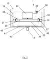
- Figure 3 shows a sectional view of the TRV 1 in Figure 1 ; the section is taken along section B-B of Figure 1 .
- the pressure chamber 19 is located within the housing 15.
- the pressure chamber 19 has within it a motor 23 configured to drive a peristaltic pump 25.
- the peristaltic pump 25 comprises a tube 27 and a wheel 29 comprising a multiplicity of lobes 31 (shown in Figure 3 ) around its perimeter, and bearings 33.
- the tube 27 is disposed between the lobes 31 of the wheel 29 and the interior wall of the pressure chamber 19.
- the tube 27 has an inlet 35 and an outlet 37 (shown in Figure 3 ).
- the tube enables air transfer between the pressure chamber 19 and the outside environment such that the pressure in the chamber 19 can be decreased, increased, or maintained, via a suitable rotation of the wheel 29.
- the motor 23 is configured to drive the rotation of the wheel 29 of the peristaltic pump 25.
- the motor 23 driving the wheel 29 of the peristaltic pump 25 in a forward direction increases the pressure within the pressure chamber 19, while driving the wheel 29 in the rearward direction decreases the pressure within the pressure chamber 19.
- the wheel 29 is held in position by the motor 23 there is no substantial increase or decrease in pressure within the pressure chamber 19.
- the lobes 31 of the wheel 29 seal the pressure chamber 19 when the wheel 29 is held in a fixed position, by preventing air from passing through the tube 27 past the position of the lobe 31.
- the motor 23 according to the first embodiment of the invention is an electric motor.
- the motor 23 receives power from the battery 21 (not shown in Figure 2 but schematically illustrated in Figure 1 ) via a power cable 34 which passes through the wall of the pressure chamber 19.
- the interface between the power cable 34 and the wall is sealed 36 to prevent air egress from the pressure chamber 19.
- the diaphragm 39 On the bottom of the pressure chamber is a 5cm diameter diaphragm 39.
- the diaphragm has an interior face 41 and an exterior face 43.
- the exterior face 43 is configured to contact the valve pin 13 of the valve body 5.
- the interface between the diaphragm 39 and the pressure chamber 19 is sealed by seals 45 which prevent pressure egress from the pressure chamber 19.
- the exterior surface 43 of the diaphragm 39 is configured to abut a first end of the valve pin 13.
- the valve pin 13 is connected at its other end to the valve element 11 (see Figure 1 ) such that downward movement of the valve pin 13 closes the valve. Increasing the pressure within the pressure chamber 19 increases the force applied to the valve pin 13. Decreasing the pressure within the pressure chamber 19 decreases the force applied to the valve pin 13.
- the diaphragm has a range of movement.
- the range of movement of the diaphragm 39 is the maximum difference in displacement of the diaphragm when the pressure chamber 19 is at its extremes of low- and high-pressure achievable in operation.
- the diaphragm 39 is arranged to have a possible range of movement of between 1mm and 10mm to make it useable on a range of valves.
- the diaphragm typically undergoes a range of movement of between 1 and 3mm because that is the range of movement of the valve pin in this embodiment.
- actuation assembly comprises a peristaltic pump
- the above-mentioned arrangement is able to exert a 90N force on the valve pin 13 with around 0.5bar within the pressure chamber 19.
- gearbox that might otherwise be needed for the motor to directly drive the valve pin. This may enable the noise, bulk and/or complexity of the TRV to be reduced, and facilitates a relatively quiet and compact TRV.
- the TRV 1 is configured to connect wirelessly to the smart network and the TRV 1 comprises a receiver configured to receive signals from a thermostat, that control the operation of the TRV 1 within the heating system.
- a controller (not shown) controls the operation of the peristaltic pump 25 to alter the position of the valve pin 13.
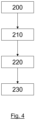
- Figure 4 shows a flow diagram of a control scenario in a second embodiment of the invention.
- the controller receives 200 a temperature measurement input from a thermometer and compares 210 this to a desired temperature set point (communicated by a central thermostat in a heating system).
- the controller generates 220 a value for a valve set point which will achieve the desired temperature set point and calculates the motor position required to obtain the pressure within the pressure chamber which will achieve the valve set point.
- the controller then instructs 230 the required motor position to the TRV 1.
- the peristaltic pump may be located outside the pressure chamber and comprises an outlet that feeds into the pressure chamber.
- the actuation assembly may be located in a boiler valve of a heating system as defined in claim 8.
Landscapes
- Engineering & Computer Science (AREA)
- General Engineering & Computer Science (AREA)
- Mechanical Engineering (AREA)
- Physics & Mathematics (AREA)
- Thermal Sciences (AREA)
- Chemical & Material Sciences (AREA)
- Combustion & Propulsion (AREA)
- Details Of Valves (AREA)
- Reciprocating Pumps (AREA)
Claims (9)
- Ein Heizkörper-Thermostatventil (1), das einen Ventilkopf (3) und einen Ventilkörper (5) beinhaltet, wobei der Ventilkopf (3) eine Antriebsanordnung (17) zum Bewegen einer Ventilnadel (13) des Ventilkörpers (5) beinhaltet, wobei die Antriebsanordnung (17) Folgendes beinhaltet:eine Druckkammer (19);eine Pneumatikpumpe (25), die dazu eingerichtet ist, den Druck in der Druckkammer (19) einzustellen; undein Ausgangselement zum Anstoßen an der Ventilnadel (13);wobei das Ausgangselement dazu eingerichtet ist, sich als Reaktion auf eine Druckänderung in der Druckkammer (19) zu bewegen, sodass die Druckänderung eine Bewegung der Ventilnadel (13) bewirkt; undwobei das Ausgangselement eine Membran (39) beinhaltet und es sich bei der Pneumatikpumpe (25) um eine Peristaltikpumpe handelt.
- Heizkörper-Thermostatventil (1) gemäß einem der vorhergehenden Ansprüche, wobei sich die Pneumatikpumpe (25) in der Druckkammer (19) befindet.
- Heizkörper-Thermostatventil (1) gemäß einem der vorhergehenden Ansprüche, wobei die Antriebsanordnung (17) einen Elektromotor (23) beinhaltet, der dazu eingerichtet ist, die Pneumatikpumpe (25) anzutreiben.
- Heizkörper-Thermostatventil (1) gemäß einem der vorhergehenden Ansprüche, wobei das Heizkörper-Thermostatventil (1) dazu konfiguriert ist, ein Temperaturmesswertsignal zu empfangen, und die Pneumatikpumpe (25) in Abhängigkeit von dem Temperaturmesswertsignal gesteuert wird.
- Ein Heizkörper-Thermostatventilkopf (3) zum Verbinden mit einem Ventilkörper (5), wobei der Ventilkopf (3) die Antriebsanordnung (17) zum Bewegen einer Ventilnadel (13) des Ventilkörpers (5) gemäß einem der Ansprüche 1 bis 4 beinhaltet.
- Ein Heizkörper, der das Heizkörper-Thermostatventil gemäß einem der Ansprüche 1 bis 4 beinhaltet.
- Ein Verfahren zum Steuern eines Heizkörper-Thermostatventils (1) gemäß einem der Ansprüche 1 bis 4,
wobei das Verfahren die folgenden Schritte beinhaltet:Empfangen (200) eines Temperaturmesswerts;Vergleichen (210) des Temperaturmesswerts mit einem Temperatursollwert;Einstellen des Drucks in der Druckkammer (19) des Heizkörper-Thermostatventils (1) auf den erforderlichen Druck, sodass das Ausgangselement die Ventilnadel (13) auf einen zum Erreichen des Temperatursollwerts erforderlichen Ventilsollwert einstellt. - Ein Heizkesselventil in einer Heizungsanlage, wobei das Ventil einen Ventilkörper (5) mit einer Ventilnadel (13) und einem eine Antriebsanordnung (17) zum Bewegen der Ventilnadel (13) beinhaltenden Ventilkopf (3) beinhaltet, wobei die Antriebsanordnung (17) Folgendes beinhaltet:eine Druckkammer (19);eine Pneumatikpumpe (25), die dazu eingerichtet ist, den Druck in der Druckkammer (19) einzustellen; undein Ausgangselement zum Anstoßen an der Ventilnadel (13);wobei das Ausgangselement dazu eingerichtet ist, sich als Reaktion auf eine Druckänderung in der Druckkammer (19) zu bewegen, sodass die Druckänderung eine Bewegung der Ventilnadel (13) bewirkt; undwobei das Ausgangselement eine Membran (39) beinhaltet und es sich bei der Pneumatikpumpe (25) um eine Peristaltikpumpe handelt.
- Heizkesselventil gemäß Anspruch 8, wobei es sich bei dem Heizkesselventil um ein Dreiwegeventil handelt.
Priority Applications (1)
| Application Number | Priority Date | Filing Date | Title |
|---|---|---|---|
| EP19176043.8A EP3742059B1 (de) | 2019-05-22 | 2019-05-22 | Betätigungsanordnung in einem thermostatischen heizkörperventil |
Applications Claiming Priority (1)
| Application Number | Priority Date | Filing Date | Title |
|---|---|---|---|
| EP19176043.8A EP3742059B1 (de) | 2019-05-22 | 2019-05-22 | Betätigungsanordnung in einem thermostatischen heizkörperventil |
Publications (2)
| Publication Number | Publication Date |
|---|---|
| EP3742059A1 EP3742059A1 (de) | 2020-11-25 |
| EP3742059B1 true EP3742059B1 (de) | 2024-12-18 |
Family
ID=66676201
Family Applications (1)
| Application Number | Title | Priority Date | Filing Date |
|---|---|---|---|
| EP19176043.8A Active EP3742059B1 (de) | 2019-05-22 | 2019-05-22 | Betätigungsanordnung in einem thermostatischen heizkörperventil |
Country Status (1)
| Country | Link |
|---|---|
| EP (1) | EP3742059B1 (de) |
Families Citing this family (1)
| Publication number | Priority date | Publication date | Assignee | Title |
|---|---|---|---|---|
| EP4556769A1 (de) * | 2023-11-17 | 2025-05-21 | Danfoss A/S | Autonomer hilfsöffnungsmechanismus zum öffnen eines geschlossenen heizkörperventils und heizsystem |
Family Cites Families (3)
| Publication number | Priority date | Publication date | Assignee | Title |
|---|---|---|---|---|
| DE19534181A1 (de) * | 1995-09-15 | 1997-03-27 | Danfoss As | Ferneinstellvorrichtung, insbesondere für eine Heizeinrichtung |
| DE19852654C2 (de) * | 1998-11-16 | 2001-05-17 | Danfoss As | Aufsatz für ein Ventil, insbesondere Heizungsventil |
| GB2560964A (en) * | 2017-03-30 | 2018-10-03 | Richard Brown Phillip | Return temperature limiter remote sensor and actuator |
-
2019
- 2019-05-22 EP EP19176043.8A patent/EP3742059B1/de active Active
Also Published As
| Publication number | Publication date |
|---|---|
| EP3742059A1 (de) | 2020-11-25 |
Similar Documents
| Publication | Publication Date | Title |
|---|---|---|
| KR100929211B1 (ko) | 정유량 자동제어장치 | |
| US4523436A (en) | Incrementally adjustable electronic expansion valve | |
| US20090248210A1 (en) | Time pulse pilot for pressure regulating control valve | |
| US8490885B2 (en) | Integrated freeze protection and pressure relief valve | |
| US3967781A (en) | Electrically operated expansion valve for refrigeration control | |
| WO1998013605A3 (en) | Integrated electrically operable micro-valve | |
| CA2424381A1 (en) | Body fluid flow control method and device | |
| US20100032594A1 (en) | Freeze protection valve | |
| CN113389716B (zh) | 隔膜泵和压力调节设备 | |
| EP0783643B9 (de) | Ventil für ein wärmeträgersystem | |
| EP3742059A1 (de) | Betätigungsanordnung in einem thermostatischen heizkörperventil | |
| WO2011133166A1 (en) | Integrated freeze protection and pressure relief valve | |
| WO2018078443A2 (en) | Force limited valve actuator and method therefor | |
| KR101662672B1 (ko) | 자가발전기능을 갖는 자율적응형 풍력발전수단이 구비된 공조시스템 | |
| US10007278B2 (en) | Pneumatic valve and use thereof for a connected consumer | |
| CN102999067B (zh) | 恒温器阀盖 | |
| EP3078890B1 (de) | Zweistufiges ventil | |
| EP3382492B1 (de) | Thermostatischer aktuator für heizkörperventil und zonenheizsystem damit | |
| KR101991500B1 (ko) | 공압식 액추에이터, 이를 이용한 공압식 밸브 및 공압식 밸브 시스템 | |
| EP2660495B1 (de) | Steuerventileinheit eines Flüssigkeitskreises eines Verbrennungsmotors | |
| CA2713962C (en) | Supply manifold for hydronic system | |
| EP0783642B1 (de) | Ventil für ein wärmeträgersystem | |
| KR102566473B1 (ko) | 밸브의 유압 임계 값을 결정하기 위한 조정 장치 및 방법 | |
| RU2306495C1 (ru) | Электроприводной вихревой теплогенератор | |
| CN215720993U (zh) | 自力式温控换向阀 |
Legal Events
| Date | Code | Title | Description |
|---|---|---|---|
| PUAI | Public reference made under article 153(3) epc to a published international application that has entered the european phase |
Free format text: ORIGINAL CODE: 0009012 |
|
| STAA | Information on the status of an ep patent application or granted ep patent |
Free format text: STATUS: THE APPLICATION HAS BEEN PUBLISHED |
|
| AK | Designated contracting states |
Kind code of ref document: A1 Designated state(s): AL AT BE BG CH CY CZ DE DK EE ES FI FR GB GR HR HU IE IS IT LI LT LU LV MC MK MT NL NO PL PT RO RS SE SI SK SM TR |
|
| AX | Request for extension of the european patent |
Extension state: BA ME |
|
| STAA | Information on the status of an ep patent application or granted ep patent |
Free format text: STATUS: REQUEST FOR EXAMINATION WAS MADE |
|
| 17P | Request for examination filed |
Effective date: 20210428 |
|
| RBV | Designated contracting states (corrected) |
Designated state(s): AL AT BE BG CH CY CZ DE DK EE ES FI FR GB GR HR HU IE IS IT LI LT LU LV MC MK MT NL NO PL PT RO RS SE SI SK SM TR |
|
| STAA | Information on the status of an ep patent application or granted ep patent |
Free format text: STATUS: EXAMINATION IS IN PROGRESS |
|
| 17Q | First examination report despatched |
Effective date: 20230620 |
|
| P01 | Opt-out of the competence of the unified patent court (upc) registered |
Effective date: 20230827 |
|
| RAP3 | Party data changed (applicant data changed or rights of an application transferred) |
Owner name: PITTWAY SARL |
|
| GRAP | Despatch of communication of intention to grant a patent |
Free format text: ORIGINAL CODE: EPIDOSNIGR1 |
|
| STAA | Information on the status of an ep patent application or granted ep patent |
Free format text: STATUS: GRANT OF PATENT IS INTENDED |
|
| RIC1 | Information provided on ipc code assigned before grant |
Ipc: F16K 37/00 20060101ALI20240627BHEP Ipc: F24D 19/10 20060101AFI20240627BHEP |
|
| INTG | Intention to grant announced |
Effective date: 20240709 |
|
| GRAS | Grant fee paid |
Free format text: ORIGINAL CODE: EPIDOSNIGR3 |
|
| GRAA | (expected) grant |
Free format text: ORIGINAL CODE: 0009210 |
|
| STAA | Information on the status of an ep patent application or granted ep patent |
Free format text: STATUS: THE PATENT HAS BEEN GRANTED |
|
| AK | Designated contracting states |
Kind code of ref document: B1 Designated state(s): AL AT BE BG CH CY CZ DE DK EE ES FI FR GB GR HR HU IE IS IT LI LT LU LV MC MK MT NL NO PL PT RO RS SE SI SK SM TR |
|
| REG | Reference to a national code |
Ref country code: CH Ref legal event code: EP |
|
| REG | Reference to a national code |
Ref country code: DE Ref legal event code: R096 Ref document number: 602019063567 Country of ref document: DE |
|
| REG | Reference to a national code |
Ref country code: IE Ref legal event code: FG4D |
|
| REG | Reference to a national code |
Ref country code: LT Ref legal event code: MG9D |
|
| PG25 | Lapsed in a contracting state [announced via postgrant information from national office to epo] |
Ref country code: HR Free format text: LAPSE BECAUSE OF FAILURE TO SUBMIT A TRANSLATION OF THE DESCRIPTION OR TO PAY THE FEE WITHIN THE PRESCRIBED TIME-LIMIT Effective date: 20241218 |
|
| PG25 | Lapsed in a contracting state [announced via postgrant information from national office to epo] |
Ref country code: FI Free format text: LAPSE BECAUSE OF FAILURE TO SUBMIT A TRANSLATION OF THE DESCRIPTION OR TO PAY THE FEE WITHIN THE PRESCRIBED TIME-LIMIT Effective date: 20241218 |
|
| PG25 | Lapsed in a contracting state [announced via postgrant information from national office to epo] |
Ref country code: BG Free format text: LAPSE BECAUSE OF FAILURE TO SUBMIT A TRANSLATION OF THE DESCRIPTION OR TO PAY THE FEE WITHIN THE PRESCRIBED TIME-LIMIT Effective date: 20241218 |
|
| PG25 | Lapsed in a contracting state [announced via postgrant information from national office to epo] |
Ref country code: NO Free format text: LAPSE BECAUSE OF FAILURE TO SUBMIT A TRANSLATION OF THE DESCRIPTION OR TO PAY THE FEE WITHIN THE PRESCRIBED TIME-LIMIT Effective date: 20250318 |
|
| REG | Reference to a national code |
Ref country code: NL Ref legal event code: MP Effective date: 20241218 |
|
| PG25 | Lapsed in a contracting state [announced via postgrant information from national office to epo] |
Ref country code: LV Free format text: LAPSE BECAUSE OF FAILURE TO SUBMIT A TRANSLATION OF THE DESCRIPTION OR TO PAY THE FEE WITHIN THE PRESCRIBED TIME-LIMIT Effective date: 20241218 Ref country code: GR Free format text: LAPSE BECAUSE OF FAILURE TO SUBMIT A TRANSLATION OF THE DESCRIPTION OR TO PAY THE FEE WITHIN THE PRESCRIBED TIME-LIMIT Effective date: 20250319 |
|
| PG25 | Lapsed in a contracting state [announced via postgrant information from national office to epo] |
Ref country code: RS Free format text: LAPSE BECAUSE OF FAILURE TO SUBMIT A TRANSLATION OF THE DESCRIPTION OR TO PAY THE FEE WITHIN THE PRESCRIBED TIME-LIMIT Effective date: 20250318 |
|
| PG25 | Lapsed in a contracting state [announced via postgrant information from national office to epo] |
Ref country code: NL Free format text: LAPSE BECAUSE OF FAILURE TO SUBMIT A TRANSLATION OF THE DESCRIPTION OR TO PAY THE FEE WITHIN THE PRESCRIBED TIME-LIMIT Effective date: 20241218 |
|
| REG | Reference to a national code |
Ref country code: AT Ref legal event code: MK05 Ref document number: 1752504 Country of ref document: AT Kind code of ref document: T Effective date: 20241218 |
|
| PG25 | Lapsed in a contracting state [announced via postgrant information from national office to epo] |
Ref country code: SM Free format text: LAPSE BECAUSE OF FAILURE TO SUBMIT A TRANSLATION OF THE DESCRIPTION OR TO PAY THE FEE WITHIN THE PRESCRIBED TIME-LIMIT Effective date: 20241218 |
|
| PG25 | Lapsed in a contracting state [announced via postgrant information from national office to epo] |
Ref country code: PL Free format text: LAPSE BECAUSE OF FAILURE TO SUBMIT A TRANSLATION OF THE DESCRIPTION OR TO PAY THE FEE WITHIN THE PRESCRIBED TIME-LIMIT Effective date: 20241218 |
|
| PGFP | Annual fee paid to national office [announced via postgrant information from national office to epo] |
Ref country code: DE Payment date: 20250626 Year of fee payment: 7 |
|
| PG25 | Lapsed in a contracting state [announced via postgrant information from national office to epo] |
Ref country code: ES Free format text: LAPSE BECAUSE OF FAILURE TO SUBMIT A TRANSLATION OF THE DESCRIPTION OR TO PAY THE FEE WITHIN THE PRESCRIBED TIME-LIMIT Effective date: 20241218 |
|
| PGFP | Annual fee paid to national office [announced via postgrant information from national office to epo] |
Ref country code: GB Payment date: 20250520 Year of fee payment: 7 |
|
| PG25 | Lapsed in a contracting state [announced via postgrant information from national office to epo] |
Ref country code: IS Free format text: LAPSE BECAUSE OF FAILURE TO SUBMIT A TRANSLATION OF THE DESCRIPTION OR TO PAY THE FEE WITHIN THE PRESCRIBED TIME-LIMIT Effective date: 20250418 |
|
| PG25 | Lapsed in a contracting state [announced via postgrant information from national office to epo] |
Ref country code: PT Free format text: LAPSE BECAUSE OF FAILURE TO SUBMIT A TRANSLATION OF THE DESCRIPTION OR TO PAY THE FEE WITHIN THE PRESCRIBED TIME-LIMIT Effective date: 20250421 |
|
| PG25 | Lapsed in a contracting state [announced via postgrant information from national office to epo] |
Ref country code: EE Free format text: LAPSE BECAUSE OF FAILURE TO SUBMIT A TRANSLATION OF THE DESCRIPTION OR TO PAY THE FEE WITHIN THE PRESCRIBED TIME-LIMIT Effective date: 20241218 |
|
| PG25 | Lapsed in a contracting state [announced via postgrant information from national office to epo] |
Ref country code: AT Free format text: LAPSE BECAUSE OF FAILURE TO SUBMIT A TRANSLATION OF THE DESCRIPTION OR TO PAY THE FEE WITHIN THE PRESCRIBED TIME-LIMIT Effective date: 20241218 Ref country code: RO Free format text: LAPSE BECAUSE OF FAILURE TO SUBMIT A TRANSLATION OF THE DESCRIPTION OR TO PAY THE FEE WITHIN THE PRESCRIBED TIME-LIMIT Effective date: 20241218 |
|
| PG25 | Lapsed in a contracting state [announced via postgrant information from national office to epo] |
Ref country code: SK Free format text: LAPSE BECAUSE OF FAILURE TO SUBMIT A TRANSLATION OF THE DESCRIPTION OR TO PAY THE FEE WITHIN THE PRESCRIBED TIME-LIMIT Effective date: 20241218 |
|
| PG25 | Lapsed in a contracting state [announced via postgrant information from national office to epo] |
Ref country code: CZ Free format text: LAPSE BECAUSE OF FAILURE TO SUBMIT A TRANSLATION OF THE DESCRIPTION OR TO PAY THE FEE WITHIN THE PRESCRIBED TIME-LIMIT Effective date: 20241218 |
|
| PG25 | Lapsed in a contracting state [announced via postgrant information from national office to epo] |
Ref country code: IT Free format text: LAPSE BECAUSE OF FAILURE TO SUBMIT A TRANSLATION OF THE DESCRIPTION OR TO PAY THE FEE WITHIN THE PRESCRIBED TIME-LIMIT Effective date: 20241218 |
|
| PG25 | Lapsed in a contracting state [announced via postgrant information from national office to epo] |
Ref country code: SE Free format text: LAPSE BECAUSE OF FAILURE TO SUBMIT A TRANSLATION OF THE DESCRIPTION OR TO PAY THE FEE WITHIN THE PRESCRIBED TIME-LIMIT Effective date: 20241218 |
|
| REG | Reference to a national code |
Ref country code: DE Ref legal event code: R097 Ref document number: 602019063567 Country of ref document: DE |
|
| PG25 | Lapsed in a contracting state [announced via postgrant information from national office to epo] |
Ref country code: DK Free format text: LAPSE BECAUSE OF FAILURE TO SUBMIT A TRANSLATION OF THE DESCRIPTION OR TO PAY THE FEE WITHIN THE PRESCRIBED TIME-LIMIT Effective date: 20241218 |
|
| PLBE | No opposition filed within time limit |
Free format text: ORIGINAL CODE: 0009261 |
|
| STAA | Information on the status of an ep patent application or granted ep patent |
Free format text: STATUS: NO OPPOSITION FILED WITHIN TIME LIMIT |
|
| REG | Reference to a national code |
Ref country code: CH Ref legal event code: L10 Free format text: ST27 STATUS EVENT CODE: U-0-0-L10-L00 (AS PROVIDED BY THE NATIONAL OFFICE) Effective date: 20251029 |
|
| 26N | No opposition filed |
Effective date: 20250919 |
|
| REG | Reference to a national code |
Ref country code: CH Ref legal event code: H13 Free format text: ST27 STATUS EVENT CODE: U-0-0-H10-H13 (AS PROVIDED BY THE NATIONAL OFFICE) Effective date: 20251223 |
|
| PG25 | Lapsed in a contracting state [announced via postgrant information from national office to epo] |
Ref country code: LU Free format text: LAPSE BECAUSE OF NON-PAYMENT OF DUE FEES Effective date: 20250522 |
|
| PG25 | Lapsed in a contracting state [announced via postgrant information from national office to epo] |
Ref country code: CH Free format text: LAPSE BECAUSE OF NON-PAYMENT OF DUE FEES Effective date: 20250531 |
|
| REG | Reference to a national code |
Ref country code: BE Ref legal event code: MM Effective date: 20250531 |
|
| PG25 | Lapsed in a contracting state [announced via postgrant information from national office to epo] |
Ref country code: MC Free format text: LAPSE BECAUSE OF FAILURE TO SUBMIT A TRANSLATION OF THE DESCRIPTION OR TO PAY THE FEE WITHIN THE PRESCRIBED TIME-LIMIT Effective date: 20241218 |
|
| PG25 | Lapsed in a contracting state [announced via postgrant information from national office to epo] |
Ref country code: IE Free format text: LAPSE BECAUSE OF NON-PAYMENT OF DUE FEES Effective date: 20250522 |
|
| PG25 | Lapsed in a contracting state [announced via postgrant information from national office to epo] |
Ref country code: BE Free format text: LAPSE BECAUSE OF NON-PAYMENT OF DUE FEES Effective date: 20250531 |
|
| PG25 | Lapsed in a contracting state [announced via postgrant information from national office to epo] |
Ref country code: FR Free format text: LAPSE BECAUSE OF NON-PAYMENT OF DUE FEES Effective date: 20250531 |