EP3742065A1 - Elektronische steueranordnung und klimaanlage - Google Patents
Elektronische steueranordnung und klimaanlage Download PDFInfo
- Publication number
- EP3742065A1 EP3742065A1 EP18900031.8A EP18900031A EP3742065A1 EP 3742065 A1 EP3742065 A1 EP 3742065A1 EP 18900031 A EP18900031 A EP 18900031A EP 3742065 A1 EP3742065 A1 EP 3742065A1
- Authority
- EP
- European Patent Office
- Prior art keywords
- electronic control
- section
- limit
- control box
- box assembly
- Prior art date
- Legal status (The legal status is an assumption and is not a legal conclusion. Google has not performed a legal analysis and makes no representation as to the accuracy of the status listed.)
- Withdrawn
Links
- 238000006073 displacement reaction Methods 0.000 claims description 12
- 230000007704 transition Effects 0.000 claims description 9
- 230000001154 acute effect Effects 0.000 claims description 7
- 238000010586 diagram Methods 0.000 description 2
- 230000000694 effects Effects 0.000 description 2
Images


Classifications
-
- F—MECHANICAL ENGINEERING; LIGHTING; HEATING; WEAPONS; BLASTING
- F24—HEATING; RANGES; VENTILATING
- F24F—AIR-CONDITIONING; AIR-HUMIDIFICATION; VENTILATION; USE OF AIR CURRENTS FOR SCREENING
- F24F13/00—Details common to, or for air-conditioning, air-humidification, ventilation or use of air currents for screening
- F24F13/20—Casings or covers
-
- F—MECHANICAL ENGINEERING; LIGHTING; HEATING; WEAPONS; BLASTING
- F24—HEATING; RANGES; VENTILATING
- F24F—AIR-CONDITIONING; AIR-HUMIDIFICATION; VENTILATION; USE OF AIR CURRENTS FOR SCREENING
- F24F11/00—Control or safety arrangements
- F24F11/89—Arrangement or mounting of control or safety devices
-
- F—MECHANICAL ENGINEERING; LIGHTING; HEATING; WEAPONS; BLASTING
- F24—HEATING; RANGES; VENTILATING
- F24F—AIR-CONDITIONING; AIR-HUMIDIFICATION; VENTILATION; USE OF AIR CURRENTS FOR SCREENING
- F24F13/00—Details common to, or for air-conditioning, air-humidification, ventilation or use of air currents for screening
- F24F13/20—Casings or covers
- F24F2013/207—Casings or covers with control knobs; Mounting controlling members or control units therein
Definitions
- the present invention relates to the technical field of air conditioners, in particular to an electronic control assembly and an air conditioner.
- An air conditioner contains an electronic control box, which is used to control the start and stop and operation of the air conditioner.
- the electronic control box needs to be fixed to the base.
- the electronic control box is connected to the base through multiple screws, and the use of screws is prone to produce screw column to be striped and other phenomena with unreliable quality. With the use of screw connection, the whole is not easy to detach. And the production efficiency of the screwing is low, which increases the cost.
- an electronic control assembly is proposed in the present invention.
- the electronic control assembly is convenient to detach, which reduces the cost of the electronic control assembly.
- An electronic control assembly includes a base and an electronic control box assembly, wherein a limiting member is disposed on the electronic control box assembly, a mounting member is disposed on the base, and the limiting member cooperate with the mounting member to limit the electronic control box assembly from moving relative to the base and to fix the electronic control box assembly and the base.
- the limiting member includes a limit portion, and the limit portion is disposed on one side of the electronic control box assembly.
- An abut portion is disposed on the mounting member, and the limit portion abuts against the abut portion.
- the abut portion includes an abut surface
- the limit portion includes a limit surface. After the limit portion slides into position relative to the abut portion, the limit surface abuts against the abut surface to limit a displacement of the electronic control box assembly relative to the base.
- the limit portion includes a first guide surface
- the abut portion includes a second guide surface. After the first guide surface (8) slides into position relative to the second guide surface, the limit surface abuts against the abut surface.
- the limit portion includes a guide section and a limit section, the guide section is connected to the mounting member, and the limit section is connected to one end of the guide section and is disposed at an acute angle.
- the second guide surface is disposed on one side of the guide section away from the limit section, and the limit surface is disposed on one side of the limit section away from the guide section.
- the limit portion further includes a reset section, and one end of the reset section is connected to one end of the limit section away from the guide section.
- the reset section drives the limit section and the guide section to rotate, so that the limit surface is released from abutment with the abut surface.
- the limiting member includes a latching portion, a snap portion is disposed in the mounting member, and the latching portion is latched with the snap portion.
- the latching portion includes a first latching segment and a second latching segment that are connected to each other and are L-shaped.
- the first latching segment has one end connected to the electronic control box assembly (3), and the other end connected to the second latching segment.
- the snap portion is a snap hole
- the snap hole comprises a first section, a transition section, and a second section.
- the first section is connected to the second section through the transition section, and a width of the first section is larger than a width of the second section.
- the electronic control assembly includes a base and an electronic control box assembly, wherein a limiting member is disposed on the electronic control box assembly, a mounting member is disposed on the base, and the limiting member cooperate with the mounting member to limit the electronic control box assembly from moving relative to the base and to fix the electronic control box assembly and the base.
- the cooperation of the limiting member and the mounting member can restrict the movement of the electronic control box assembly relative to the base, and can fix the electronic control box assembly and the base.
- the electronic control assembly is easy to detach, which reduces the cost of the electronic control assembly.
- Another object of the present invention is to provide an air conditioner, which is easy to disassemble and can reduce the cost of the electronic control assembly.
- An air conditioner includes an electronic control assembly.
- the electronic control assembly includes a base and an electronic control box assembly, wherein a limiting member is disposed on the electronic control box assembly, a mounting member is disposed on the base, and the limiting member cooperate with the mounting member to limit the electronic control box assembly from moving relative to the base and to fix the electronic control box assembly and the base.
- an electronic control assembly 1 is provided in this embodiment.
- the electronic control assembly 1 in this embodiment is easy to detach, which reduces the cost of the electronic control assembly 1.
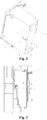
- the electronic control assembly 1 includes a base 2 and an electronic control box assembly 3, wherein a limiting member 4 is disposed on the electronic control box assembly 3, a mounting member 5 is disposed on the base 2, and the limiting member 4 cooperates with the mounting member 5 to limit the electronic control box assembly 3 from moving relative to the base 2 and to fix the electronic control box assembly 3 and the base 2.
- the limiting member 4 cooperates with the mounting member 5 to limit the electronic control box assembly 3 from moving relative to the base 2 and to fix the electronic control box assembly 3 and the base 2.
- the electronic control assembly 1 is easy to detach, which reduces the cost of the electronic control assembly 1.
- the limiting member 4 includes a limit portion 6, and the limit portion 6 is disposed on one side of the electronic control box assembly 3.
- the limit portion 6 abuts against the mounting surface 5 to limit a displacement of the electronic control box assembly 3 relative to the base 2.
- the limit portion 6 has a limit surface 7. After the limit portion 6 slides into position relative to the mounting member 5, the limit surface 7 abuts against the mounting member 5 to limit a displacement of the electronic control box assembly 3 relative to the base 2.
- the limit portion 6 has a guide surface 8. After the guide surface 8 is slid into position relative to the mounting member 5, the limit surface 7 abuts against the mounting member 5.
- the limit portion 6 is a triangular prism, and the triangular prism has three side surfaces and two end surfaces, wherein one side surface is connected to a side wall of the electronic control box assembly 3. In another two side surfaces, one side surface is the abut surface 13, and the other is the first guide surface 8. Both the abut surface 13 and the first guide surface 8 extend to the side wall of the electronic control box assembly 3.
- the abut surface 13 is perpendicular to the side wall of the electronic control box assembly 3, and the first guide surface 8 is disposed at an acute angle with the side wall of the electronic control box assembly 3.
- the abut surface 13 is perpendicular to the side wall of the electronic control box assembly 3, and the first guide surface 8 is disposed at an acute angle with the side wall of the electronic control box assembly 3.
- the abut surface 13 is disposed at an acute angle with the side wall of the electronic control box assembly 3
- the first guide surface 8 is perpendicular to the side wall of the electronic control box assembly 3
- both the abut surface 13 and the first guide surface 8 is disposed at an acute angle with the side wall of the electronic control box assembly 3.
- the limiting member 4 further includes a latching portion 9, and the latching portion 9 is latched with the mounting member 5 for fixing the base 2 and the limiting member 4.
- the latching portion 9 is disposed at a bottom wall of the electronic box assembly 3 adjacent to the limit portion 6.
- the latching portion 9 includes a first latching segment 10 and a second latching segment 11 that are connected to each other and are L-shaped.
- the first latching segment 10 has one end connected to the electronic control box assembly 3, and the other end connected to the second latching segment 11.
- the second latching section 11 passes through the mounting member 5, and the first latching section 10 and the second latching section 11 move relative to the mounting member 5, so that the first latching section 10 abuts against the second latching section for fixing the base 2 and the electronic box assembly 3.
- the electronic box assembly 3 includes an electronic control box 23 and a protection plate 24, wherein the protection plate 24 is disposed outside the electronic control box 23, and in this embodiment, the limit portion 6 is disposed on the protection plate 24.
- the electronic control box assembly 3 includes the electronic control box 23 and the protection plate 24, which is not limited herein. In other embodiments of the present invention, the electronic box assembly 3 may only include the electronic control box 23, and the limit portion 6 is disposed on the electronic control box 23. Any solutions equivalent to this embodiment that may achieve the effects of this embodiment is within the protection scope of the present invention.
- an abut portion 12 is disposed on the mounting member 5, and the limit portion 6 abuts against the abut portion 12.
- the abut portion 12 has an abut surface 13. After the limit portion 6 is slid into position relative to the abut portion 12, the limit surface 7 abuts against the abut surface 13 to limit a displacement of the electronic control box assembly 3 relative to the base 2.
- the abut portion 12 has a second guide surface 14. After the first guide surface 8 is slid into position relative to the second guide surface 14, the limit surface 7 abuts against the abut surface 13.
- the first guide surface 8 abuts against the second guide surface 14 and slides relative to the second guide surface 14.
- the abut surface 13 abuts against the limit surface 7 to limit a displacement of the electronic control box assembly 3 relative to the base 2.
- the first guide surface 8 abuts against the second guide surface 14 and slides relative to the second guide surface 14.
- the first guide surface 8 slides relative to the second guide surface 14 to disengage from the second guide surface 14, indicating that the first guide surface 8 slides into position relative to the second guide surface 14.
- the limit portion 6 includes a guide section 15 and a limit section 16, wherein the guide section 15 is connected to the mounting member 5, the limit section 16 is connected to one end of the guide section 15 away from the mounting member 5 and disposed at an acute angle.
- the guide surface is disposed at one side of the guide section 15 away from the limit section 16, and the limit surface 7 is disposed at one side of the limit section 16 away from the guide section 15.
- the limit portion 6 further includes a reset section 17, and one end of the reset section 17 is connected to one end of the limit section 16 away from the guide section 15.
- the reset section 17 may drive the limit section 16 and the guide section 15 to rotate, so that the limit surface 7 is released from abutment with the abut surface 13.
- the limit surface 7 abuts against the abut surface 13 after the first guide surface 8 slides into position relative to the second guide surface 14 to limit a displacement of the electronic control box assembly 3 relative to the base 2.
- the reset section 17 is pushed, and the reset section 17 drives the limit section 16 and the guide section 15 to move close to the electronic control box assembly 3 relative to the base 2, so that the abut surface 13 is released from abutment with the limit surface 7, and the electronic control box assembly 3 is released from limit with the base 2, so as to remove the electronic control box assembly 3.
- a snap portion 18 is disposed on the mounting member 5, and the latching portion 9 is latched with the snap portion 18.
- the snap portion 18 is a snap hole, and the snap hole includes a first section 19, a transition section 20, and a second section 21.
- the first section 19 is connected to the second section 21 through the transition section 20, and a width of the first section 19 is larger than a width of the second section 21.
- the transition section 20 is transitionally connected to the first section 19 and the second section 21.
- a width of the first section 19 is greater than a width of the second section 21.
- the first section 19 is used as a guide section 15 and the second section 21 is a fixed section.
- the second latching section 11 After the second latching section 11 enters into the second section 21 through the transition section 20 by the guide of the first section 19, the second latching section 11 abuts against a side wall of the mounting member 5 to limit a displacement of the electronic control box assembly 3 in a direction perpendicular to the mounting member 5, and the first latching section 10 abuts against the second section 21 for cooperating with the second section 21 to limit displacements of the electronic control box assembly 3 in three directions in a plane parallel to the mounting member 5. Except for the direction in which the second section 21 is communicated with the first section 19, displacements in other directions are limited.
- the width of the first section 19 is greater than the width of the second section 21, the second latching section 11 passes through the first section 19, and the first latching section 10 and the second latching section 11 move close to the second section 21. After the first latching section 10 and the second latching section 11 move to the second section 21, the first latching section 10 abuts against the second section 21 to fix the electronic box assembly 3.
- the abut surface 13 is parallel to the opposite side walls of the first section 19 and the second section 21.
- the abut surface 13 abuts against the limit surface 7, so that a displacement in a direction in which the first section 19 is communicated with the second section 21 is limited to fix the electronic control box assembly 3.
- the working principle of the electronic control assembly 1 is: in this embodiment, when the second latching section 11 moves close to the second section 21 through the mounting member 5 by the first section 19, the first guide surface 8 abuts against the second guide surface 14, and the first guide surface 8 slides relative to the second guide surface 14. After the first guide surface 8 slides into position relative to the second guide surface 14, the abut surface 13 abuts against the limit surface 7. And the first latching section 10 slides into a region where the second section 21 is located.
- the reset section 17 When the electronic control box assembly 3 is required to disassemble, the reset section 17 is pushed, and the reset section 17 drives the guide section 15 and the abut section to move close to the electronic control box assembly 3 relative to the base 2, so that the abut surface 13 is released from abutment with the limit surface 7. After the abut surface 13 is released from abutment with the limit surface 7, the electronic control box assembly 3 moves away from the second section 21, and the second latching section 11 is removed from the first section 19, so as to disassemble the electronic control box assembly 3.
- the electronic control assembly 1 is this embodiment may limit the displacement of the electronic control box assembly 3 relative to the base 2 for fixing the electronic control box assembly 3.
- the electronic control box assembly 3 and the base 2 are easy to disassemble, which reduces the cost of the electronic control assembly 1.
- This embodiment provides an air conditioner (not shown).
- the air conditioner in this embodiment is easy to disassemble, which may reduce the cost of the air conditioner.
- the air conditioner includes the electronic control assembly 1 is the embodiments and a housing (air conditioner), wherein the base 2 is connected to the housing.
Landscapes
- Engineering & Computer Science (AREA)
- Chemical & Material Sciences (AREA)
- Combustion & Propulsion (AREA)
- Mechanical Engineering (AREA)
- General Engineering & Computer Science (AREA)
- Casings For Electric Apparatus (AREA)
- Air Filters, Heat-Exchange Apparatuses, And Housings Of Air-Conditioning Units (AREA)
- Mounting Components In General For Electric Apparatus (AREA)
- Cooling Or The Like Of Electrical Apparatus (AREA)
Applications Claiming Priority (2)
| Application Number | Priority Date | Filing Date | Title |
|---|---|---|---|
| CN201820060319.7U CN207741276U (zh) | 2018-01-15 | 2018-01-15 | 一种电控组件及空调 |
| PCT/CN2018/125494 WO2019137260A1 (zh) | 2018-01-15 | 2018-12-29 | 一种电控组件及空调 |
Publications (2)
| Publication Number | Publication Date |
|---|---|
| EP3742065A1 true EP3742065A1 (de) | 2020-11-25 |
| EP3742065A4 EP3742065A4 (de) | 2021-10-06 |
Family
ID=63123177
Family Applications (1)
| Application Number | Title | Priority Date | Filing Date |
|---|---|---|---|
| EP18900031.8A Withdrawn EP3742065A4 (de) | 2018-01-15 | 2018-12-29 | Elektronische steueranordnung und klimaanlage |
Country Status (7)
| Country | Link |
|---|---|
| EP (1) | EP3742065A4 (de) |
| JP (1) | JP7045452B2 (de) |
| CN (1) | CN207741276U (de) |
| AU (1) | AU2018401188B2 (de) |
| MY (1) | MY204269A (de) |
| NZ (1) | NZ765678A (de) |
| WO (1) | WO2019137260A1 (de) |
Families Citing this family (3)
| Publication number | Priority date | Publication date | Assignee | Title |
|---|---|---|---|---|
| CN207741276U (zh) * | 2018-01-15 | 2018-08-17 | 奥克斯空调股份有限公司 | 一种电控组件及空调 |
| CN109959132A (zh) * | 2019-04-22 | 2019-07-02 | 宁波奥克斯电气股份有限公司 | 一种电控盒安装结构及空调器 |
| WO2021134902A1 (zh) * | 2019-12-31 | 2021-07-08 | 广东美的制冷设备有限公司 | 空调器 |
Family Cites Families (13)
| Publication number | Priority date | Publication date | Assignee | Title |
|---|---|---|---|---|
| DE3034007A1 (de) * | 1980-09-10 | 1982-04-15 | Walter Ing.(Grad.) 7000 Stuttgart Dreizler | Raumluftklappe |
| KR100389429B1 (ko) * | 2001-06-19 | 2003-06-27 | 주식회사 엘지이아이 | 공기조화기의 콘트롤박스 장착구조 |
| JP3841067B2 (ja) | 2003-06-25 | 2006-11-01 | ダイキン工業株式会社 | 空気調和装置の室内機の電装ユニット |
| KR100680621B1 (ko) * | 2005-10-27 | 2007-02-08 | 삼성전자주식회사 | 공기조화기 |
| EP1953461A1 (de) * | 2007-01-26 | 2008-08-06 | LG Electronics Inc. | Inneneinheit einer Klimaanlage mit beweglicher Frontabdeckung zur Luftansaugung von der Vorderseite und vertikaler Fortluft |
| JP5317915B2 (ja) | 2009-09-29 | 2013-10-16 | 三菱電機株式会社 | 空気調和機 |
| JP5317920B2 (ja) | 2009-10-13 | 2013-10-16 | 三菱電機株式会社 | リモコン用送受信器及びこれを備えた空気調和機 |
| CN204494640U (zh) * | 2015-02-09 | 2015-07-22 | 广东美的暖通设备有限公司 | 电控盒和空调器 |
| CN205842855U (zh) * | 2016-06-25 | 2016-12-28 | 宁波奥克斯空调有限公司 | 空调室内挂机 |
| CN206073295U (zh) * | 2016-09-22 | 2017-04-05 | 江苏新科电器有限公司 | 挂壁室内机底座 |
| CN206469429U (zh) * | 2016-11-28 | 2017-09-05 | 广东美的暖通设备有限公司 | 空调器 |
| CN107518854A (zh) * | 2017-08-08 | 2017-12-29 | 佛山市顺德区美的洗涤电器制造有限公司 | 电控盒及洗碗机 |
| CN207741276U (zh) * | 2018-01-15 | 2018-08-17 | 奥克斯空调股份有限公司 | 一种电控组件及空调 |
-
2018
- 2018-01-15 CN CN201820060319.7U patent/CN207741276U/zh active Active
- 2018-12-29 EP EP18900031.8A patent/EP3742065A4/de not_active Withdrawn
- 2018-12-29 WO PCT/CN2018/125494 patent/WO2019137260A1/zh not_active Ceased
- 2018-12-29 MY MYPI2020003325A patent/MY204269A/en unknown
- 2018-12-29 NZ NZ765678A patent/NZ765678A/en not_active IP Right Cessation
- 2018-12-29 JP JP2020524410A patent/JP7045452B2/ja active Active
- 2018-12-29 AU AU2018401188A patent/AU2018401188B2/en active Active
Also Published As
| Publication number | Publication date |
|---|---|
| EP3742065A4 (de) | 2021-10-06 |
| AU2018401188B2 (en) | 2022-01-13 |
| NZ765678A (en) | 2022-05-27 |
| MY204269A (en) | 2024-08-20 |
| CN207741276U (zh) | 2018-08-17 |
| JP7045452B2 (ja) | 2022-03-31 |
| WO2019137260A1 (zh) | 2019-07-18 |
| AU2018401188A1 (en) | 2020-04-02 |
| JP2021503174A (ja) | 2021-02-04 |
Similar Documents
| Publication | Publication Date | Title |
|---|---|---|
| EP3742065A1 (de) | Elektronische steueranordnung und klimaanlage | |
| US10036561B2 (en) | Indoor unit for air conditioner | |
| CN101929599B (zh) | 挂架 | |
| CN209541036U (zh) | 清洁部件、空调器室内机和空调器 | |
| CN218633477U (zh) | 直线电机定子结构和直线电机 | |
| CN113746242B (zh) | 一种电机安装结构及空调器 | |
| CN204648528U (zh) | 机壳及空调室外机 | |
| CN210070046U (zh) | 底座及空调器 | |
| CN219624242U (zh) | 一种空调器的底座组件和空调器 | |
| US7517030B2 (en) | Slide rail structure for industry-used computers | |
| CN113251582B (zh) | 一种显示盒固定结构及具有其的空调器 | |
| CN205878352U (zh) | 壁挂式空调室内机和空调器 | |
| CN209801627U (zh) | 出风结构及具有其的空调室内机 | |
| CN212108680U (zh) | 空调器室内机 | |
| CN211177359U (zh) | 导风组件的驱动装置、落地式空调室内机和空调器 | |
| CN219955487U (zh) | 导风板驱动机构及空调器 | |
| CN222354264U (zh) | 一种控制箱以及投影仪 | |
| CN104728936B (zh) | 空调器室内机 | |
| CN118398992B (zh) | 储能模块及储能装置 | |
| CN205372978U (zh) | 空调器的安装结构 | |
| CN219692874U (zh) | 一种门禁控制器的安装结构 | |
| CN204678618U (zh) | 水位开关的固定结构及空调器 | |
| CN223242866U (zh) | 连接结构及空调 | |
| CN217817366U (zh) | 阀门组件和具有其的空调器 | |
| CN222514079U (zh) | 安装结构及吸顶机 |
Legal Events
| Date | Code | Title | Description |
|---|---|---|---|
| STAA | Information on the status of an ep patent application or granted ep patent |
Free format text: STATUS: THE INTERNATIONAL PUBLICATION HAS BEEN MADE |
|
| PUAI | Public reference made under article 153(3) epc to a published international application that has entered the european phase |
Free format text: ORIGINAL CODE: 0009012 |
|
| STAA | Information on the status of an ep patent application or granted ep patent |
Free format text: STATUS: REQUEST FOR EXAMINATION WAS MADE |
|
| 17P | Request for examination filed |
Effective date: 20200323 |
|
| AK | Designated contracting states |
Kind code of ref document: A1 Designated state(s): AL AT BE BG CH CY CZ DE DK EE ES FI FR GB GR HR HU IE IS IT LI LT LU LV MC MK MT NL NO PL PT RO RS SE SI SK SM TR |
|
| AX | Request for extension of the european patent |
Extension state: BA ME |
|
| DAV | Request for validation of the european patent (deleted) | ||
| DAX | Request for extension of the european patent (deleted) | ||
| A4 | Supplementary search report drawn up and despatched |
Effective date: 20210903 |
|
| RIC1 | Information provided on ipc code assigned before grant |
Ipc: F24F 13/20 20060101ALI20210827BHEP Ipc: F24F 13/00 20060101ALI20210827BHEP Ipc: F24F 11/89 20180101AFI20210827BHEP |
|
| STAA | Information on the status of an ep patent application or granted ep patent |
Free format text: STATUS: THE APPLICATION IS DEEMED TO BE WITHDRAWN |
|
| 18D | Application deemed to be withdrawn |
Effective date: 20220402 |