EP3742216B1 - Agencement optique pour microscopie à plan oblique - Google Patents
Agencement optique pour microscopie à plan oblique Download PDFInfo
- Publication number
- EP3742216B1 EP3742216B1 EP20156593.4A EP20156593A EP3742216B1 EP 3742216 B1 EP3742216 B1 EP 3742216B1 EP 20156593 A EP20156593 A EP 20156593A EP 3742216 B1 EP3742216 B1 EP 3742216B1
- Authority
- EP
- European Patent Office
- Prior art keywords
- optical
- sample
- image
- light
- optical subassembly
- Prior art date
- Legal status (The legal status is an assumption and is not a legal conclusion. Google has not performed a legal analysis and makes no representation as to the accuracy of the status listed.)
- Active
Links
Images





Classifications
-
- G—PHYSICS
- G02—OPTICS
- G02B—OPTICAL ELEMENTS, SYSTEMS OR APPARATUS
- G02B21/00—Microscopes
- G02B21/0004—Microscopes specially adapted for specific applications
- G02B21/002—Scanning microscopes
- G02B21/0024—Confocal scanning microscopes (CSOMs) or confocal "macroscopes"; Accessories which are not restricted to use with CSOMs, e.g. sample holders
- G02B21/0052—Optical details of the image generation
- G02B21/0076—Optical details of the image generation arrangements using fluorescence or luminescence
-
- G—PHYSICS
- G02—OPTICS
- G02B—OPTICAL ELEMENTS, SYSTEMS OR APPARATUS
- G02B21/00—Microscopes
- G02B21/16—Microscopes adapted for ultraviolet illumination ; Fluorescence microscopes
Definitions
- SPIM Selective Plane Illumination Microscopy
- SPIM has been used to obtain images of small organisms and embryos and can be used to image both reflected or scattered light and fluorescence [5].
- SPIM The drawback of SPIM is that two objective lenses are required and this gives rise to the two main disadvantages of this technique.
- Second, the need to illuminate the sample with a lens that is in the plane of the sample being imaged means that conventional sample preparation techniques, e.g. glass microscope slides, cannot be used, and a special sample holder needs to be used instead.
- This system is nearly equivalent to a SPIM system, but with two significant differences; the illumination and detection beams are not at 90° (as is usual for SPIM) and the sheet of illumination does not align in the focal plane of the imaging system used to collect the reflected/scattered light or fluorescence.
- This is shown in the image plane of Figure 2 , where the image of the sample fluorescence (shown as a stripe) lies at significant angle to the image plane (dashed line).
- the detector cannot simply be tilted with respect to the optical axis due to unwanted spherical aberrations that would arise. This aberration will be most severe for parts of the image of the sample image that are furthest from the image plane.
- WO 2008/078083 discloses a focusing apparatus for use with an optical system.
- the focusing apparatus includes a focus adjusting means, which enables the position of a selected axial focal plane to be adjusted within the sample.
- a system may include a relay lens configured to form an intermediate image of light scattered by a specimen.
- the relay lens may be positioned at an oblique viewing angle from an upper surface of the specimen.
- the system may also include a reflection grating positioned such that the intermediate image is imaged on the reflection grating.
- the reflection grating may be configured to reflect the intermediate image.
- the reflection grating may be positioned negative to the upper surface of the specimen, at the natural image plane.
- the system may include an objective lens configured to focus the reflected intermediate image.
- the system may further include an area detector configured to produce a signal representative of the focused image. An image of the specimen may be formed from the produced signal.
- the first optical subassembly comprises a first part arranged to produce a magnified image of the sample, and a second part arranged to de-magnify the image obtained from the first part and thereby form the intermediate image.
- the first optical subassembly is configured to produce the intermediate image with a magnification of unity in both the lateral and axial directions. By recreating the original sample both laterally and axially in the intermediate image, this minimizes the effect of aberrations.
- the first optical subassembly images the sample whilst in an immersion medium (e.g. water or oil) then the magnification of the first optical subassembly is preferably equal to the refractive index of this immersion medium.
- the intermediate image is also formed in an immersion medium, then the total magnification of the first optical subassembly is preferably equal to the ratio of the refractive indices of the two immersion media.
- the first optical subassembly is preferably configured to produce the intermediate image with a magnification of M in both the lateral and axial directions, where M is equal to the ratio (n 1 /n 2 ) of the refractive indices of the first and second immersion media.
- first and second optical subassemblies may be formed using separate physical components, according to the invention they share common optical components, thereby making the overall optical arrangement potentially more compact.
- a plane mirror is situated at the focus of the second part of the first optical subassembly (e.g. as is shown in Figure 3 ).
- the numerical aperture of the first optical subassembly is greater than the numerical aperture of the second optical subassembly.
- the said objective lens has a high numerical aperture.
- a light source is arranged to provide an incident beam of light to illuminate or excite an oblique plane in the sample, the oblique plane illuminated/excited corresponding to the oblique plane being imaged.
- the incident beam of light is directed through the same objective lens as that which is used to receive light from the sample.
- a single objective lens in this manner reduces the number of components in the overall assembly, and potentially makes it more compact and manoeuvrable, particularly in the vicinity of the sample.
- a high numerical aperture lens can be used to collect the light while still being able to produce a thin sheet of illumination.
- conventional sample preparation techniques e.g. glass microscope slides, can be employed.
- the incident beam of light is directed through the objective lens such that it is incident on the sample at an angle of substantially 90° relative to the beam of light received from the sample through the same objective lens.
- the incident beam of light may be directed along the whole of the first optical subassembly.
- Such a configuration enables all the optical components required for oblique plane microscopy to be placed outside the body of a 'conventional' microscope.
- the components defining the illumination beam path and the second optical subassembly may be mounted on a common platform, and actuation means may be provided for translating the components defining the illumination beam path and the second optical subassembly together. This enables the plane being imaged to be moved through the sample, without affecting or moving the sample itself.
- the optical arrangement may further comprise means for changing the magnification of the said objective lens, and means for changing one or more optical components elsewhere in the optical arrangement in correspondence with the change in magnification of the said objective lens, so as to maintain a desired overall magnification within the first optical subassembly.
- the optical arrangement may further comprise an image rotating prism such as a Dove prism behind the said objective lens, in order to be able to change the orientation of the oblique illumination plane and the obliquely imaged plane in the sample simultaneously, without the need to physically rotate relatively large parts of the apparatus.
- an image rotating prism such as a Dove prism behind the said objective lens
- the optical arrangement may be arranged such that the image contrast arises from light reflected or scattered by the sample, or from the polarization state of the reflected or scattered light.
- the optical arrangement may be arranged such that the image contrast arises from fluorescent light emitted from the sample, optionally as a result of a multiphoton excitation process.
- the fluorescent light may be excited at one or more wavelengths and detected in corresponding detection bands at longer (for single photon excitation) or shorter (for multiphoton excitation) wavelengths than each excitation wavelength.
- the image contrast may arise from differences in the fluorescence lifetime of the sample, or from the polarization state of the emitted fluorescence.
- the optical arrangement may be arranged to image particles or cells flowing through the oblique image plane, for example in a microfluidic device.
- it may be set up in combination with an electronically-controlled stage for positioning the sample or for moving the sample in one or more directions. By scanning the sample in one or more directions it is then possible to build up a 3D image of the sample.
- the second optical subassembly is arranged to have a combination of both a long working distance and a high numerical aperture, so as to facilitate the avoidance of collisions with the optical elements that make up the first optical subassembly.
- the fluorescence may originate from single individually-resolvable molecules.
- the method may further comprise adjusting the number of fluorescent molecules in the sample by activating or deactivating the fluorescence via a photoactivation or photo-switching mechanism, thereby enabling molecules to be individually resolved.
- the photoactivation or photo-switching mechanism may be controlled by illumination of the sample (that may be wide-field or may be an oblique illumination) at one or more additional wavelengths.
- the method may further comprise modifying the excitation sheet so that it is exhibits a more complex form such as a sinusoidal grating. Additional resolution may be obtained by modulating the position or phase of the complex illumination (e.g. sinusoidal grating) and acquiring a plurality of images at different modulations.
- modifying the excitation sheet so that it is exhibits a more complex form such as a sinusoidal grating. Additional resolution may be obtained by modulating the position or phase of the complex illumination (e.g. sinusoidal grating) and acquiring a plurality of images at different modulations.
- a method of performing oblique plane microscopy comprising directing an incident beam of light through an objective lens to illuminate or excite an oblique plane in a sample, and receiving light from the sample through the same objective lens, wherein the incident beam of light is incident on the sample at an angle of substantially 90° relative to the beam of light received from the sample.
- a microscope comprising an optical arrangement in accordance with the first aspect of the invention, or which is configured for performing a method in accordance with the second or third aspects of the invention.
- Optical elements may be added to a conventional microscope to form embodiments of the invention.
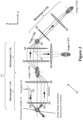
- Figure 3 is a schematic diagram of an embodiment of the aberration correction principle according to the present invention.
- the present technique may be referred to as oblique plane microscopy (OPM).
- OPM oblique plane microscopy
- the optical arrangement 10 of Figure 3 may be integrated in a microscope, or provided as a "bolt-on" attachment for existing microscopes.
- the first optical subassembly 17 may be regarded as comprising a first microscope part 14 and a second microscope part 16.
- the first microscope part 14, which comprises lenses 26 and 28, produces a magnified image 30 (Image 1) of the sample 12.
- the second microscope part 16, which comprises lenses 32 and 34, is arranged to de-magnify the image 30 to produce the intermediate image 36 (Image 2) which corresponds to the sample 12.
- the intermediate image 36 is at a magnification of unity in both the axial and lateral directions (in the case that lens 26 operates in air) with respect to the sample 12.
- lenses 32 and 34 compensate for (or "undo") any aberrations produced by lenses 26 and 28.
- the first optical subassembly 17 may be implemented with any number of optical elements that achieves the same result.
- the rays of light leave lens 34 and converge (towards the point of the intermediate image 36) about an angle relative to the optical axis of lens 34, the angle corresponding to the angle of the selected plane within the sample 12 relative to the optical axis of the objective lens 26.
- These converging rays are then collected by the second optical subassembly 18.
- the focal point of lens 38 of the second optical subassembly 18 coincides with the focal point of the converging rays leaving lens 34, and the optical axis of lens 38 is centred about the rays leaving lens 34.
- optical aberrations are generally designed to magnify or focus light received at their designed focal plane without introducing optical aberrations. Accordingly, since the objective lens 38 of the second optical subassembly 18 receives the incoming light centrally about its designed focal plane, rather than at an angle, it is able to magnify the selected plane without introducing optical aberrations.
- the second optical subassembly 18 focusing on and magnifying the intermediate image 36 (rather than the sample 12 itself), the second optical subassembly 18 is able to re-image any plane in the intermediate image 36 without the need to adjust or disturb the specimen 12.
- This concept is similar to the ideas presented in [8], with the important exception that now an oblique plane in the specimen is imaged.
- the light rays 24 emitted (or reflected or scattered) from the sample will be emitted in all directions.
- the numerical aperture of the objective lens 38 of the second optical subassembly 18 places the restriction on the range of angles of light that are ultimately collected by the detector or CCD camera 48.
- Image contrast may be achieved in a number of ways. It may arise from light reflected or scattered by the sample. In fluorescence microscopy, the image contrast may arise from fluorescent light excited at one or more wavelengths and detected in corresponding detection bands at longer wavelengths than each excitation wavelength. Alternatively, the image contrast may arise from differences in the fluorescence lifetime of the sample.
- the image contrast may arise from the polarization state of the reflected or scattered light, or the polarization state of the emitted fluorescence.
- the second optical subassembly 18 may be produced as a distinct set of optical components (e.g. lenses 38 and 40), in the embodiments according to the invention, the second optical subassembly shares common optical components with parts of the first optical subassembly 17, whilst also achieving the same level of compensation against aberrations.
- One example of such an embodiment produces magnified image 47 rather than image 42, and involves placing an obliquely angled mirror along the plane indicated by a solid line 44 at the intermediate focal plane (image 36), resulting in image 47 (Image 3') being produced (via mirror 45 and lens 46).
- the angle of the mirror at the intermediate focal plane is half the angle of the slope of the oblique plane being imaged.
- Mirror 45 may also consist of a larger partially reflective mirror that covers the whole back aperture of lens 34.
- the concept of using a second optical subassembly 18 at an angle to a first optical subassembly 17, as described above, may be used separately from the concept of a common objective lens 26 for directing the illumination and collected beams at 90° to one another, and vice versa.
- Figures 4 and 5 illustrate laboratory prototypes of examples which are not part of the invention. In essence, the optical arrangements in Figures 4 and 5 function in the same way as that of Figure 3 as described above. However, being laboratory prototypes, the arrangements of Figures 4 and 5 provide additional practical details that are useful for putting the present invention into practice.
- the angle of the illumination 22 can be controlled by translating the slit 23.
- the thickness of the 'sheet' illumination at lens 26 can be controlled by changing the width of the slit 23.
- Figure 4 shows a fluorescent sphere as the object at the focus of lens 26.
- the stripe indicates the region where fluorescence is excited.
- the subsequent images 30, 36 and 42 (at lenses 28, 34 and 40) indicate how the image of the object is distorted (these images are not to scale and serve only to illustrate the distortion).
- the optical configuration has been made more light efficient, as less of the excitation light 22 is blocked by the slit 23.
- the angle of the illumination can be controlled by the angle of mirror M1.
- the width of the 'sheet' illumination at lens 26 can be controlled by changing the width of the slit 23.
- a slit 81 may be used to adjust the width of the laser beam and hence the thickness of the illumination sheet. Other arrangements to adjust the position and width of the illumination sheet may be employed, as will be known by those skilled in the art.
- the optical axis of the illumination beam path 84 is preferably placed at an angle of 90° to the axis of the second optical subassembly 18.
- the components defining the illumination beam path 84 and the second optical subassembly 18 may be advantageous to mount the components defining the illumination beam path 84 and the second optical subassembly 18 on the same mechanical platform. This will allow the illumination beam path 84 and the second optical subassembly 18 to be translated together in one or more dimensions using manual or motorized actuator(s). As the illumination and detection beam paths (84, 18) are accurately relayed to the sample 12 by the first optical subassembly 17, movement of the illumination and detection beam paths (84, 18) together will cause the plane illuminated and imaged to be moved through the sample 12. This movement of the illumination and detection beam paths (84, 18) can be achieved without affecting or moving the sample itself, and so will not perturb or cause vibrations in the sample 12.
- an image rotating prism e.g. a Dove prism or such like, immediately behind the back aperture of the objective lens 26 in order to change the orientation of the oblique illumination plane and the obliquely imaged plane in the sample simultaneously, without the need to physically rotate relatively large parts of the apparatus.
- An optical arrangement embodying the present invention may be integrated in a microscope, or provided as a "bolt-on" attachment for an existing microscope. Indeed, a conventional microscope could be used to provide the functionality of the first microscope part 14, provided a sufficiently high NA objective lens 26 is employed.
- the optical arrangement may be combined with an electronically-controlled stage for positioning the sample or for moving the sample in one or more directions. By scanning the sample in one or more directions it is then possible to build up a 3D image of the sample.
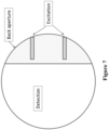
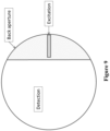
- Figure 8 is a diagram showing the angular distribution of beams at the sample.
- the geometry of Figure 8 is as follows: Excitation and detection rays intersect at 90° at the sample.
- NA n sin ⁇
- ⁇ ex 10°
- ⁇ em 30°
- the confocal parameter is given by 2z r , which equals 10 ⁇ m in this example. Decreasing ⁇ ex will increase the confocal parameter at the expense of increasing the thickness of the illumination sheet (or 'z' resolution).
Landscapes
- Physics & Mathematics (AREA)
- Chemical & Material Sciences (AREA)
- Analytical Chemistry (AREA)
- General Physics & Mathematics (AREA)
- Optics & Photonics (AREA)
- Microscoopes, Condenser (AREA)
- Investigating, Analyzing Materials By Fluorescence Or Luminescence (AREA)
Claims (21)
- Agencement optique pour la microscopie à plan oblique comprenant :un premier sous-ensemble optique (17), comportant une lentille de focalisation (26) agencée pour recevoir de la lumière en provenance d'un échantillon (12) à l'usage, et conçu pour produire une image intermédiaire (36) de l'échantillon (12), le premier sous-ensemble optique comprenant une première partie (14) agencée pour produire une image grossie (30) de l'échantillon, et une deuxième partie (16) agencée pour réduire le grossissement de l'image obtenue à partir de la première partie et former ainsi l'image intermédiaire ;un deuxième sous-ensemble optique mis au point sur l'image intermédiaire (36), l'axe optique du deuxième sous-ensemble optique formant un certain angle par rapport à l'axe optique du premier sous-ensemble optique (17) en un point de l'image intermédiaire (36), de sorte que le deuxième sous-ensemble optique image un plan oblique dans l'image intermédiaire (36) correspondant à un plan oblique dans l'échantillon (12), le deuxième sous-ensemble optique comprenant un miroir (45) et une lentille (46) destinés à produire une image grossie (47) ; etun miroir plan (44) au foyer de la deuxième partie du premier sous-ensemble optique, le miroir plan étant incliné obliquement à la moitié de l'angle de la pente du plan oblique qui est imagé,dans lequel les premier et deuxième sous-ensembles optiques partagent une lentille commune (34).
- Agencement optique selon la revendication 1, dans lequel une source de lumière est agencée pour fournir un faisceau incident de lumière pour éclairer ou exciter un plan oblique dans l'échantillon (12), le plan oblique éclairé/excité correspondant au plan oblique qui est imagé.
- Agencement optique selon la revendication 2, dans lequel ladite lentille de focalisation (26) présente une ouverture numérique élevée, dans lequel le faisceau incident de lumière est dirigé à travers ladite lentille de focalisation (26), éventuellement de telle sorte qu'il est incident sur l'échantillon (12) à un angle sensiblement égal à 90° par rapport au faisceau de lumière reçu de l'échantillon (12) à travers ladite lentille de focalisation (26).
- Agencement optique selon la revendication 2 ou 3, dans lequel les composants définissant le trajet du faisceau incident et le deuxième sous-ensemble optique sont montés sur une plate-forme commune, l'agencement optique comprenant en outre éventuellement des moyens d'actionnement destinés à translater ensemble les composants définissant le trajet du faisceau incident et le deuxième sous-ensemble optique.
- Agencement optique selon l'une quelconque des revendications 1 à 4, dans lequel le premier sous-ensemble optique (17) est conçu pour produire l'image intermédiaire (36) avec un grossissement unitaire à la fois dans la direction latérale et axiale.
- Agencement optique selon l'une quelconque des revendications 1 à 4 dans lequel, si l'échantillon (12) est placé dans un premier milieu d'immersion ayant un indice de réfraction n1, ou si l'image intermédiaire est formée dans un deuxième milieu d'immersion ayant un indice de réfraction n2, alors le premier sous-ensemble optique (17) est conçu pour produire l'image intermédiaire (36) avec un grossissement de M à la fois dans la direction latérale et axiale, où M est égal au rapport (n1/n2) des indices de réfraction des premier et deuxième milieux d'immersion.
- Agencement optique selon une quelconque revendication précédente, dans lequel l'ouverture numérique du premier sous-ensemble optique (17) est supérieure à l'ouverture numérique du deuxième sous-ensemble optique.
- Agencement optique selon une quelconque revendication précédente, comprenant en outre des moyens pour changer le grossissement de ladite lentille de focalisation (26) et des moyens pour changer un ou plusieurs composants optiques ailleurs dans l'agencement optique en correspondance avec le changement de grossissement de ladite lentille de focalisation, de manière à conserver un grossissement global souhaité à l'intérieur du premier sous-ensemble optique (17).
- Agencement optique selon une quelconque revendication précédente, agencé de telle sorte que le contraste d'image résulte de la lumière réfléchie ou diffusée par l'échantillon (12), éventuellement de telle sorte que le contraste d'image résulte de l'état de polarisation de la lumière réfléchie ou diffusée.
- Agencement optique selon une quelconque revendication précédente, agencé pour imager des particules ou cellules s'écoulant à travers le plan image oblique, par exemple dans un dispositif microfluidique.
- Agencement optique selon la revendication 2, ou l'une quelconque des revendications 3 à 10 lorsqu'elles sont dépendantes de la revendication 2, comprenant en outre :un miroir (M1) agencé pour contrôler un angle du faisceau incident de lumière ; etune fente (23) agencée pour contrôler une largeur du faisceau incident de lumière, la fente se trouvant à une position entre le miroir et la source de lumière.
- Agencement optique selon la revendication 2, ou l'une quelconque des revendications 3 à 10 lorsqu'elles sont dépendantes de la revendication 2, agencé pour coupler le faisceau incident de lumière à travers la totalité du premier sous-ensemble optique (17).
- Agencement optique selon une quelconque revendication précédente, agencé pour modeler un éclairage par feuille d'excitation dans le plan de la feuille d'excitation.
- Procédé de réalisation d'une microscopie à plan oblique comprenant :la réception de lumière en provenance d'un échantillon par le biais d'un premier sous-ensemble optique (17) et la production d'une image intermédiaire (36) de l'échantillon (12), le premier sous-ensemble optique comprenant une première partie (14) agencée pour produire une image grossie (30) de l'échantillon, et une deuxième partie (16) agencée pour réduire le grossissement de l'image obtenue à partir de la première partie et former ainsi l'image intermédiaire ;la réflexion de l'image intermédiaire hors d'un plan au foyer de la deuxième partie du premier sous-ensemble optique, le plan étant incliné obliquement à la moitié de l'angle de la pente du plan oblique qui est imagé ; etla mise au point d'un deuxième sous-ensemble optique sur l'image intermédiaire réfléchie, l'axe optique du deuxième sous-ensemble optique formant un certain angle par rapport à l'axe optique du premier sous-ensemble optique en un point de l'image intermédiaire, de sorte que le deuxième sous-ensemble optique image un plan oblique dans l'image intermédiaire correspondant à un plan oblique dans l'échantillon, le deuxième sous-ensemble optique comprenant un miroir (45) et une lentille (46) destinés à produire une image grossie (47), les premier et deuxième sous-ensembles optiques partageant une lentille commune (34).
- Procédé selon la revendication 14, comprenant en outre :
l'éclairage ou l'excitation d'un plan oblique dans l'échantillon (12) par un faisceau incident de lumière en provenance d'une source de lumière, le plan oblique éclairé/excité correspondant au plan oblique qui est imagé. - Procédé selon la revendication 15, dans lequel le faisceau incident de lumière est dirigé à travers la même lentille de focalisation (26) que celle utilisée pour recevoir de la lumière en provenance de l'échantillon.
- Procédé selon l'une quelconque des revendications 14 à 16, le procédé étant adapté pour faire fonctionner l'agencement optique selon l'une quelconque des revendications 1 à 13.
- Procédé selon l'une quelconque des revendications 14 à 17, dans lequel le contraste d'image résulte de la lumière fluorescente émise depuis l'échantillon (12), dans lequel la fluorescence provient de molécules uniques pouvant être distinguées individuellement, comprenant en outre éventuellement l'ajustement du nombre de molécules fluorescentes dans l'échantillon par activation ou désactivation de la fluorescence par le biais d'un mécanisme de photoactivation ou de photocommutation, éventuellement dans lequel, en outre, le mécanisme de photoactivation ou de photocommutation est contrôlé par éclairage de l'échantillon à une ou plusieurs longueurs d'onde supplémentaires.
- Procédé selon l'une quelconque des revendications 14 à 17, dans lequel le contraste d'image résulte de la lumière réfléchie ou diffusée par l'échantillon (12).
- Procédé selon la revendication 19 lorsqu'elle est dépendante de la revendication 15, dans lequel le faisceau incident de lumière forme une feuille d'excitation, le procédé comprenant en outre la modification de la feuille d'excitation de manière à ce qu'elle présente un réseau sinusoïdal, comprenant en outre éventuellement la modulation de la position ou de la phase de l'éclairage complexe et l'acquisition d'une pluralité d'images à différentes modulations.
- Microscope comprenant un agencement optique selon l'une quelconque des revendications 1 à 13, ou qui est conçu pour réaliser un procédé selon l'une quelconque des revendications 14 à 20.
Applications Claiming Priority (3)
| Application Number | Priority Date | Filing Date | Title |
|---|---|---|---|
| GBGB0814039.4A GB0814039D0 (en) | 2008-07-31 | 2008-07-31 | Optical arrangement for oblique plane microscopy |
| PCT/GB2009/001802 WO2010012980A1 (fr) | 2008-07-31 | 2009-07-20 | Agencement optique pour microscopie en plan oblique |
| EP09784754.5A EP2316048B1 (fr) | 2008-07-31 | 2009-07-20 | Agencement optique pour microscopie en plan oblique |
Related Parent Applications (1)
| Application Number | Title | Priority Date | Filing Date |
|---|---|---|---|
| EP09784754.5A Division EP2316048B1 (fr) | 2008-07-31 | 2009-07-20 | Agencement optique pour microscopie en plan oblique |
Publications (2)
| Publication Number | Publication Date |
|---|---|
| EP3742216A1 EP3742216A1 (fr) | 2020-11-25 |
| EP3742216B1 true EP3742216B1 (fr) | 2025-07-09 |
Family
ID=39767317
Family Applications (2)
| Application Number | Title | Priority Date | Filing Date |
|---|---|---|---|
| EP20156593.4A Active EP3742216B1 (fr) | 2008-07-31 | 2009-07-20 | Agencement optique pour microscopie à plan oblique |
| EP09784754.5A Active EP2316048B1 (fr) | 2008-07-31 | 2009-07-20 | Agencement optique pour microscopie en plan oblique |
Family Applications After (1)
| Application Number | Title | Priority Date | Filing Date |
|---|---|---|---|
| EP09784754.5A Active EP2316048B1 (fr) | 2008-07-31 | 2009-07-20 | Agencement optique pour microscopie en plan oblique |
Country Status (4)
| Country | Link |
|---|---|
| US (1) | US8582203B2 (fr) |
| EP (2) | EP3742216B1 (fr) |
| GB (1) | GB0814039D0 (fr) |
| WO (1) | WO2010012980A1 (fr) |
Families Citing this family (71)
| Publication number | Priority date | Publication date | Assignee | Title |
|---|---|---|---|---|
| DE102011000835C5 (de) | 2011-02-21 | 2019-08-22 | Leica Microsystems Cms Gmbh | Abtastmikroskop und Verfahren zur lichtmikroskopischen Abbildung eines Objektes |
| JP5829030B2 (ja) * | 2011-03-23 | 2015-12-09 | オリンパス株式会社 | 顕微鏡 |
| DE102011051042B4 (de) | 2011-06-14 | 2016-04-28 | Leica Microsystems Cms Gmbh | Abtastmikroskop und Verfahren zur lichtmikroskopischen Abbildung eines Objektes |
| DE102011054914A1 (de) * | 2011-10-28 | 2013-05-02 | Leica Microsystems Cms Gmbh | Verfahren und Anordnung zur Beleuchtung einer Probe |
| DE202011110077U1 (de) | 2011-10-28 | 2012-11-29 | Leica Microsystems Cms Gmbh | Anordnung zur Beleuchtung einer Probe |
| DE102012016346B4 (de) | 2012-08-16 | 2023-01-05 | Carl Zeiss Microscopy Gmbh | Laser-Scanning-Mikroskop |
| DE102012110077A1 (de) * | 2012-10-23 | 2014-06-26 | Karlsruher Institut für Technologie | Mikroskop mit mindestens einem Beleuchtungsstrahl in Form einer Lichtscheibe |
| US8994941B2 (en) * | 2012-11-28 | 2015-03-31 | General Electric Company | Optical system, apparatus and method for performing flow cytometry |
| DE102013001238B4 (de) * | 2013-01-25 | 2020-06-10 | Carl Zeiss Microscopy Gmbh | Lichtmikroskop und Mikroskopieverfahren |
| DE102013205115A1 (de) * | 2013-03-22 | 2014-09-25 | Leica Microsystems Cms Gmbh | SPIM-Anordnung |
| US9874736B2 (en) * | 2013-04-29 | 2018-01-23 | The Regents Of The University Of California | Apparatus and method for an inclined single plane imaging microscope box (iSPIM box) |
| DE102013105586B4 (de) | 2013-05-30 | 2023-10-12 | Carl Zeiss Ag | Vorrichtung zur Abbildung einer Probe |
| FR3010194B1 (fr) * | 2013-08-28 | 2017-10-27 | Imagine Optic | Systeme et methode de microscopie par eclairage par la tranche |
| DE102013112595B4 (de) * | 2013-11-15 | 2024-08-01 | Carl Zeiss Microscopy Gmbh | Anordnung zur Lichtblattmikroskopie |
| DE102013112596B4 (de) * | 2013-11-15 | 2023-12-28 | Carl Zeiss Microscopy Gmbh | Anordnung zur Lichtblattmikroskopie |
| DE102013112600A1 (de) | 2013-11-15 | 2015-05-21 | Carl Zeiss Microscopy Gmbh | Optisches Übertragungssystem und Mikroskop mit einem solchen Übertragungssystem |
| GB2520541A (en) * | 2013-11-25 | 2015-05-27 | European Molecular Biology Lab Embl | Optical arrangement for imaging a sample |
| DE102013019951B4 (de) | 2013-11-27 | 2023-06-15 | Carl Zeiss Microscopy Gmbh | Lichtmikroskop und Mikroskopieverfahren zum Untersuchen mehrerer mikroskopischer Objekte |
| US9823457B2 (en) * | 2014-01-08 | 2017-11-21 | The Regents Of The University Of California | Multiplane optical microscope |
| IL247445B (en) * | 2014-02-26 | 2022-07-01 | Brigham & Womens Hospital Inc | System and method for cell levitation and monitoring |
| DE102014113827A1 (de) * | 2014-09-24 | 2016-03-24 | Carl Zeiss Microscopy Gmbh | Vorrichtung zur Abbildung einer Probe |
| JP6959614B2 (ja) | 2015-10-28 | 2021-11-02 | 国立大学法人 東京大学 | 分析装置,及びフローサイトメータ |
| DE102016103182B4 (de) | 2016-02-23 | 2018-04-12 | Leica Microsystems Cms Gmbh | Lichtblattmikroskop und Verfahren zur lichtmikroskopischen Abbildung einer Probe |
| DE102016105798A1 (de) * | 2016-03-30 | 2017-10-05 | Georg-August-Universität Göttingen Stiftung Öffentlichen Rechts, Universitätsmedizin | Verfahren zum Erzeugen eines Mikroskopbildes |
| LU93021B1 (de) | 2016-04-08 | 2017-11-08 | Leica Microsystems | Verfahren und Mikroskop zum Untersuchen einer Probe |
| DE102016108384B3 (de) | 2016-05-04 | 2017-11-09 | Leica Microsystems Cms Gmbh | Vorrichtung und Verfahren zur lichtblattartigen Beleuchtung einer Probe |
| EP3465316A1 (fr) | 2016-06-03 | 2019-04-10 | Leica Microsystems CMS GmbH | Microscope à feuille de lumière et procédé microscopique présentant un microscope à feuille de lumière |
| WO2017223426A1 (fr) * | 2016-06-24 | 2017-12-28 | Howard Hughes Medical Institute | Réglage automatique de géométrie de nappe de lumière dans un microscope |
| JP7109423B2 (ja) | 2016-08-15 | 2022-07-29 | ライカ マイクロシステムズ シーエムエス ゲゼルシャフト ミット ベシュレンクテル ハフツング | ライトシート顕微鏡 |
| EP3497501B1 (fr) | 2016-08-15 | 2022-01-19 | Leica Microsystems CMS GmbH | Microscope à feuille de lumière |
| DE102016115140B4 (de) | 2016-08-16 | 2022-07-28 | Leica Microsystems Cms Gmbh | Wechselsystem für ein Mikroskop sowie Mikroskop |
| EP3507641B1 (fr) * | 2016-09-01 | 2024-07-03 | Leica Microsystems CMS GmbH | Microscope pour examiner différents plans inclinés éclairés avec un réseau de microlentilles |
| JP7130628B2 (ja) | 2016-09-16 | 2022-09-05 | ライカ マイクロシステムズ シーエムエス ゲゼルシャフト ミット ベシュレンクテル ハフツング | 光学顕微鏡 |
| US10852520B2 (en) | 2016-09-16 | 2020-12-01 | The Trustees Of Columbia University In The City Of New York | Three-dimensional imaging using swept, confocally aligned planar excitation and a customized image splitter |
| DE102016011227C5 (de) | 2016-09-19 | 2020-04-09 | Leica Microsystems Cms Gmbh | Mikroskopsystem und Verfahren zur Abbildung einer Probe unter Verwendung eines Mikroskopsystems |
| DE102016119268B3 (de) | 2016-10-10 | 2017-12-21 | Leica Microsystems Cms Gmbh | Schiefebenenmikroskop |
| JP6423841B2 (ja) * | 2016-10-11 | 2018-11-14 | 浜松ホトニクス株式会社 | 試料観察装置及び試料観察方法 |
| EP3538941B1 (fr) | 2016-11-10 | 2025-04-23 | The Trustees of Columbia University in the City of New York | Procédés d'imagerie rapide de grands échantillons à haute résolution |
| JPWO2018199080A1 (ja) | 2017-04-28 | 2020-03-12 | シンクサイト株式会社 | イメージングフローサイトメーター |
| EP3654018B1 (fr) * | 2017-07-11 | 2023-06-21 | Hamamatsu Photonics K.K. | Dispositif d'observation d'échantillon et procédé d'observation d'échantillon |
| JP7007122B2 (ja) | 2017-07-11 | 2022-01-24 | 浜松ホトニクス株式会社 | 試料観察装置及び試料観察方法 |
| EP3654020B1 (fr) * | 2017-07-11 | 2023-06-21 | Hamamatsu Photonics K.K. | Dispositif d'observation d'échantillon et procédé d'observation d'échantillon |
| DE102017116380B3 (de) | 2017-07-20 | 2018-12-20 | Leica Microsystems Cms Gmbh | Lichtblattmikroskopisches Verfahren zur Erzeugung eines Volumenbildes einer Probe und Lichtblattmikroskop |
| WO2019148008A1 (fr) | 2018-01-26 | 2019-08-01 | University Of Washington | Appareils et procédés de microscopie à feuille de lumière à balayage numérique à directions multiples |
| US11874451B2 (en) * | 2018-01-31 | 2024-01-16 | The Regents Of The University Of California | High numerical aperture selective plane illumination microscopy |
| GB2592113B (en) | 2018-06-13 | 2023-01-11 | Thinkcyte Inc | Methods and systems for cytometry |
| WO2020176591A1 (fr) * | 2019-02-27 | 2020-09-03 | Calico Life Sciences Llc | Système et procédé de microscopie à plan oblique |
| DE102019109832B3 (de) | 2019-04-12 | 2020-04-23 | Leica Microsystems Cms Gmbh | Lichtblattmikroskop und Verfahren zum Erfassen einer Messgröße |
| EP4022378B1 (fr) * | 2019-08-27 | 2026-02-18 | Leica Microsystems CMS GmbH | Dispositif et procédé pour imager un objet |
| WO2021043383A1 (fr) | 2019-09-02 | 2021-03-11 | Leica Microsystems Cms Gmbh | Microscope et procédé d'imagerie d'un objet à l'aide d'un microscope |
| GB201913703D0 (en) | 2019-09-23 | 2019-11-06 | Imperial College Innovations Ltd | Improved oblique plane microscopy |
| DE102019128681A1 (de) | 2019-10-23 | 2021-04-29 | Leica Microsystems Cms Gmbh | Optisches System für ein Lichtblattmikroskop |
| JP7556557B2 (ja) | 2019-12-27 | 2024-09-26 | シンクサイト株式会社 | フローサイトメータ性能評価方法 |
| JP7535116B2 (ja) * | 2020-01-09 | 2024-08-15 | ライカ マイクロシステムズ シーエムエス ゲゼルシャフト ミット ベシュレンクテル ハフツング | 斜面顕微鏡および斜面顕微鏡における収差を補正する方法 |
| DE102020204066A1 (de) | 2020-03-30 | 2021-09-30 | Leica Microsystems Cms Gmbh | Optische Anordnung für ein Schiefeebenenmikroskop zur Verbesserung der Auflösung |
| WO2021200960A1 (fr) | 2020-04-01 | 2021-10-07 | シンクサイト株式会社 | Dispositif d'observation |
| CN121476024A (zh) | 2020-04-01 | 2026-02-06 | 兴科尚株式会社 | 流式细胞仪 |
| EP3893039B1 (fr) | 2020-04-09 | 2023-08-23 | Leica Microsystems CMS GmbH | Microscope à plan oblique d'imagerie d'un échantillon |
| EP3907548B1 (fr) | 2020-05-04 | 2024-01-10 | Leica Microsystems CMS GmbH | Microscope à feuille de lumière et procédé d'imagerie d'un objet |
| EP3945358B1 (fr) | 2020-07-30 | 2024-04-24 | Leica Microsystems CMS GmbH | Microscope à plan oblique et son procédé de fonctionnement |
| EP4212849A4 (fr) | 2020-09-10 | 2024-08-28 | The University of Tokyo | Cytométrie en flux à imagerie |
| DE102020128524A1 (de) | 2020-10-29 | 2022-05-05 | Carl Zeiss Microscopy Gmbh | Lichtblattmikroskop und Verfahren der Lichtblattmikroskopie |
| EP4027182B1 (fr) | 2021-01-08 | 2024-10-30 | Leica Microsystems CMS GmbH | Microscopie par fluorescence à feuille de lumière pour une pluralité d'échantillons |
| CN113310964B (zh) * | 2021-06-02 | 2022-04-05 | 华中科技大学 | 一种兼容微流控芯片的数字扫描光片显微成像系统 |
| WO2023057348A1 (fr) | 2021-10-05 | 2023-04-13 | Leica Microsystems Cms Gmbh | Porte-échantillon et procédé d'imagerie d'un échantillon |
| EP4413409A1 (fr) | 2021-10-05 | 2024-08-14 | Leica Microsystems CMS GmbH | Système et procédé d'imagerie |
| EP4553559A4 (fr) * | 2022-07-06 | 2025-11-05 | Univ Hokkaido Nat Univ Corp | Microscope à fluorescence |
| EP4431911A1 (fr) | 2023-03-16 | 2024-09-18 | European Molecular Biology Laboratory | Support d'échantillon pour microscope |
| WO2025144918A1 (fr) * | 2023-12-26 | 2025-07-03 | Molecular Devices, Llc | Imagerie automatisée dans le criblage de contenu |
| CN120276139B (zh) * | 2025-06-10 | 2025-08-29 | 西湖大学 | 一种宽视场、宽波段倾斜显微成像离焦矫正装置及方法 |
| CN121253497A (zh) * | 2025-12-03 | 2026-01-02 | 南开大学 | 一种超分辨大深度三维扫描光片显微镜的方法 |
Citations (1)
| Publication number | Priority date | Publication date | Assignee | Title |
|---|---|---|---|---|
| US20030058432A1 (en) * | 2001-09-24 | 2003-03-27 | Drake Stephen John | Systems and methods for forming an image of a specimen at an oblique viewing angle |
Family Cites Families (16)
| Publication number | Priority date | Publication date | Assignee | Title |
|---|---|---|---|---|
| DE754979C (de) * | 1941-11-06 | 1954-07-19 | Zeiss Carl Fa | Elektronenmikroskop mit einer schraeg zu der Achse des Elektronen-strahlenbuendels angeordneten Beobachtungseinrichtung zum Betrachten des Leuchtschirmbildes |
| US3547512A (en) * | 1968-04-16 | 1970-12-15 | Research Corp | Optical apparatus providing focalplane-specific illumination |
| US4478482A (en) | 1981-05-11 | 1984-10-23 | Koester Charles J | Axial scanning optical system and method of examining an object plane |
| US5673144A (en) * | 1994-09-14 | 1997-09-30 | International Business Machines, Corporation | Oblique viewing microscope system |
| US5671085A (en) * | 1995-02-03 | 1997-09-23 | The Regents Of The University Of California | Method and apparatus for three-dimensional microscopy with enhanced depth resolution |
| US5793525A (en) * | 1995-09-22 | 1998-08-11 | Leica Inc. | Apparatus for adjusting the viewing angle of a microscope |
| US20030025918A1 (en) * | 2001-07-16 | 2003-02-06 | August Technology Corp. | Confocal 3D inspection system and process |
| US7265900B2 (en) | 2002-09-30 | 2007-09-04 | Applied Materials, Inc. | Inspection system with oblique viewing angle |
| DE10257423A1 (de) | 2002-12-09 | 2004-06-24 | Europäisches Laboratorium für Molekularbiologie (EMBL) | Mikroskop |
| DE10332073A1 (de) * | 2003-07-11 | 2005-02-10 | Carl Zeiss Jena Gmbh | Anordnung zur optischen Erfassung von in einer Probe angeregter und / oder rückgestreuter Lichtstrahlung mit Doppelobjektivanordnung |
| JP2005337940A (ja) * | 2004-05-28 | 2005-12-08 | Aisin Seiki Co Ltd | 表面プラズモン共鳴装置 |
| DE102004034967A1 (de) * | 2004-07-16 | 2006-02-02 | Carl Zeiss Jena Gmbh | Beleuchtungsvorrichtung für ein Lichtrastermikroskop mit punktförmiger Lichtquellenverteilung |
| GB0625775D0 (en) | 2006-12-22 | 2007-02-07 | Isis Innovation | Focusing apparatus and method |
| US7570362B2 (en) * | 2007-09-28 | 2009-08-04 | Olympus Corporation | Optical measurement apparatus utilizing total reflection |
| DE102007051405B4 (de) * | 2007-10-25 | 2014-03-20 | Leica Instruments (Singapore) Pte. Ltd. | Lichtmikroskop |
| DE102009044984A1 (de) * | 2009-09-24 | 2011-03-31 | Carl Zeiss Microimaging Gmbh | Mikroskop |
-
2008
- 2008-07-31 GB GBGB0814039.4A patent/GB0814039D0/en not_active Ceased
-
2009
- 2009-07-20 EP EP20156593.4A patent/EP3742216B1/fr active Active
- 2009-07-20 US US13/056,345 patent/US8582203B2/en active Active
- 2009-07-20 EP EP09784754.5A patent/EP2316048B1/fr active Active
- 2009-07-20 WO PCT/GB2009/001802 patent/WO2010012980A1/fr not_active Ceased
Patent Citations (1)
| Publication number | Priority date | Publication date | Assignee | Title |
|---|---|---|---|---|
| US20030058432A1 (en) * | 2001-09-24 | 2003-03-27 | Drake Stephen John | Systems and methods for forming an image of a specimen at an oblique viewing angle |
Also Published As
| Publication number | Publication date |
|---|---|
| EP2316048B1 (fr) | 2020-02-12 |
| EP3742216A1 (fr) | 2020-11-25 |
| US8582203B2 (en) | 2013-11-12 |
| GB0814039D0 (en) | 2008-09-10 |
| EP2316048A1 (fr) | 2011-05-04 |
| WO2010012980A1 (fr) | 2010-02-04 |
| US20110261446A1 (en) | 2011-10-27 |
Similar Documents
| Publication | Publication Date | Title |
|---|---|---|
| EP3742216B1 (fr) | Agencement optique pour microscopie à plan oblique | |
| US10901194B2 (en) | Large field of view, high resolution microscope | |
| EP1787157B1 (fr) | Appareil pour microscopie confocale a fluorescence | |
| US7554664B2 (en) | Laser scanning microscope | |
| JP6411472B2 (ja) | レーザスキャニング顕微鏡、および特に高解像度のスキャニング顕微鏡法で結像収差を修正する方法 | |
| JP5287252B2 (ja) | レーザ走査共焦点顕微鏡 | |
| JP5006694B2 (ja) | 照明装置 | |
| JP2009528577A (ja) | マルチモード撮像のシステム及び方法 | |
| JP2007506955A (ja) | エバネッセント波照明を備えた走査顕微鏡 | |
| WO2008064220A2 (fr) | Méthode et système de microscopie multi-photonique à grand champs à plan d'excitation confocal | |
| US20080062511A1 (en) | Laser scanning microscope for fluorescence testing | |
| US20120140057A1 (en) | Microscope for Measuring Total Reflection Fluorescence | |
| JP2004317741A (ja) | 顕微鏡およびその光学調整方法 | |
| JP2016186635A (ja) | 光走査システム | |
| JP2006243731A (ja) | スポット走査式レーザ走査型顕微鏡及び同顕微鏡を調整する方法 | |
| Fuseler et al. | Types of confocal instruments: Basic principles and advantages and disadvantages | |
| US7586086B2 (en) | Scanning imaging device for image-substraction confocal microscopy | |
| US20140293037A1 (en) | Optical microscope and method for examining a microscopic sample | |
| US12320966B2 (en) | Method and system for multi-view episcopic selective plane illumination microscope | |
| JP2009186508A (ja) | 光学顕微鏡の長焦点深度観察方法と光学顕微鏡 |
Legal Events
| Date | Code | Title | Description |
|---|---|---|---|
| PUAI | Public reference made under article 153(3) epc to a published international application that has entered the european phase |
Free format text: ORIGINAL CODE: 0009012 |
|
| STAA | Information on the status of an ep patent application or granted ep patent |
Free format text: STATUS: THE APPLICATION HAS BEEN PUBLISHED |
|
| AC | Divisional application: reference to earlier application |
Ref document number: 2316048 Country of ref document: EP Kind code of ref document: P |
|
| AK | Designated contracting states |
Kind code of ref document: A1 Designated state(s): AT BE BG CH CY CZ DE DK EE ES FI FR GB GR HR HU IE IS IT LI LT LU LV MC MK MT NL NO PL PT RO SE SI SK SM TR |
|
| STAA | Information on the status of an ep patent application or granted ep patent |
Free format text: STATUS: REQUEST FOR EXAMINATION WAS MADE |
|
| 17P | Request for examination filed |
Effective date: 20210524 |
|
| RBV | Designated contracting states (corrected) |
Designated state(s): AT BE BG CH CY CZ DE DK EE ES FI FR GB GR HR HU IE IS IT LI LT LU LV MC MK MT NL NO PL PT RO SE SI SK SM TR |
|
| STAA | Information on the status of an ep patent application or granted ep patent |
Free format text: STATUS: EXAMINATION IS IN PROGRESS |
|
| 17Q | First examination report despatched |
Effective date: 20230323 |
|
| P01 | Opt-out of the competence of the unified patent court (upc) registered |
Effective date: 20230328 |
|
| GRAP | Despatch of communication of intention to grant a patent |
Free format text: ORIGINAL CODE: EPIDOSNIGR1 |
|
| STAA | Information on the status of an ep patent application or granted ep patent |
Free format text: STATUS: GRANT OF PATENT IS INTENDED |
|
| INTG | Intention to grant announced |
Effective date: 20250311 |
|
| RIN1 | Information on inventor provided before grant (corrected) |
Inventor name: DUNSBY, CHRISTOPHER WILLIAM |
|
| GRAS | Grant fee paid |
Free format text: ORIGINAL CODE: EPIDOSNIGR3 |
|
| GRAA | (expected) grant |
Free format text: ORIGINAL CODE: 0009210 |
|
| STAA | Information on the status of an ep patent application or granted ep patent |
Free format text: STATUS: THE PATENT HAS BEEN GRANTED |
|
| AC | Divisional application: reference to earlier application |
Ref document number: 2316048 Country of ref document: EP Kind code of ref document: P |
|
| AK | Designated contracting states |
Kind code of ref document: B1 Designated state(s): AT BE BG CH CY CZ DE DK EE ES FI FR GB GR HR HU IE IS IT LI LT LU LV MC MK MT NL NO PL PT RO SE SI SK SM TR |
|
| REG | Reference to a national code |
Ref country code: GB Ref legal event code: FG4D |
|
| REG | Reference to a national code |
Ref country code: CH Ref legal event code: EP |
|
| REG | Reference to a national code |
Ref country code: IE Ref legal event code: FG4D |
|
| REG | Reference to a national code |
Ref country code: DE Ref legal event code: R096 Ref document number: 602009065552 Country of ref document: DE |
|
| PGFP | Annual fee paid to national office [announced via postgrant information from national office to epo] |
Ref country code: DE Payment date: 20250728 Year of fee payment: 17 |
|
| PGFP | Annual fee paid to national office [announced via postgrant information from national office to epo] |
Ref country code: GB Payment date: 20250722 Year of fee payment: 17 |
|
| PGFP | Annual fee paid to national office [announced via postgrant information from national office to epo] |
Ref country code: FR Payment date: 20250725 Year of fee payment: 17 |
|
| REG | Reference to a national code |
Ref country code: NL Ref legal event code: MP Effective date: 20250709 |
|
| PG25 | Lapsed in a contracting state [announced via postgrant information from national office to epo] |
Ref country code: PT Free format text: LAPSE BECAUSE OF FAILURE TO SUBMIT A TRANSLATION OF THE DESCRIPTION OR TO PAY THE FEE WITHIN THE PRESCRIBED TIME-LIMIT Effective date: 20251110 |
|
| PG25 | Lapsed in a contracting state [announced via postgrant information from national office to epo] |
Ref country code: NL Free format text: LAPSE BECAUSE OF FAILURE TO SUBMIT A TRANSLATION OF THE DESCRIPTION OR TO PAY THE FEE WITHIN THE PRESCRIBED TIME-LIMIT Effective date: 20250709 |
|
| REG | Reference to a national code |
Ref country code: AT Ref legal event code: MK05 Ref document number: 1812346 Country of ref document: AT Kind code of ref document: T Effective date: 20250709 |
|
| PG25 | Lapsed in a contracting state [announced via postgrant information from national office to epo] |
Ref country code: IS Free format text: LAPSE BECAUSE OF FAILURE TO SUBMIT A TRANSLATION OF THE DESCRIPTION OR TO PAY THE FEE WITHIN THE PRESCRIBED TIME-LIMIT Effective date: 20251109 |
|
| PG25 | Lapsed in a contracting state [announced via postgrant information from national office to epo] |
Ref country code: NO Free format text: LAPSE BECAUSE OF FAILURE TO SUBMIT A TRANSLATION OF THE DESCRIPTION OR TO PAY THE FEE WITHIN THE PRESCRIBED TIME-LIMIT Effective date: 20251009 |
|
| REG | Reference to a national code |
Ref country code: LT Ref legal event code: MG9D |
|
| PG25 | Lapsed in a contracting state [announced via postgrant information from national office to epo] |
Ref country code: AT Free format text: LAPSE BECAUSE OF FAILURE TO SUBMIT A TRANSLATION OF THE DESCRIPTION OR TO PAY THE FEE WITHIN THE PRESCRIBED TIME-LIMIT Effective date: 20250709 |
|
| PG25 | Lapsed in a contracting state [announced via postgrant information from national office to epo] |
Ref country code: FI Free format text: LAPSE BECAUSE OF FAILURE TO SUBMIT A TRANSLATION OF THE DESCRIPTION OR TO PAY THE FEE WITHIN THE PRESCRIBED TIME-LIMIT Effective date: 20250709 |
|
| PG25 | Lapsed in a contracting state [announced via postgrant information from national office to epo] |
Ref country code: HR Free format text: LAPSE BECAUSE OF FAILURE TO SUBMIT A TRANSLATION OF THE DESCRIPTION OR TO PAY THE FEE WITHIN THE PRESCRIBED TIME-LIMIT Effective date: 20250709 |
|
| PG25 | Lapsed in a contracting state [announced via postgrant information from national office to epo] |
Ref country code: GR Free format text: LAPSE BECAUSE OF FAILURE TO SUBMIT A TRANSLATION OF THE DESCRIPTION OR TO PAY THE FEE WITHIN THE PRESCRIBED TIME-LIMIT Effective date: 20251010 |
|
| PG25 | Lapsed in a contracting state [announced via postgrant information from national office to epo] |
Ref country code: SE Free format text: LAPSE BECAUSE OF FAILURE TO SUBMIT A TRANSLATION OF THE DESCRIPTION OR TO PAY THE FEE WITHIN THE PRESCRIBED TIME-LIMIT Effective date: 20250709 |
|
| PG25 | Lapsed in a contracting state [announced via postgrant information from national office to epo] |
Ref country code: LV Free format text: LAPSE BECAUSE OF FAILURE TO SUBMIT A TRANSLATION OF THE DESCRIPTION OR TO PAY THE FEE WITHIN THE PRESCRIBED TIME-LIMIT Effective date: 20250709 |
|
| PG25 | Lapsed in a contracting state [announced via postgrant information from national office to epo] |
Ref country code: BG Free format text: LAPSE BECAUSE OF FAILURE TO SUBMIT A TRANSLATION OF THE DESCRIPTION OR TO PAY THE FEE WITHIN THE PRESCRIBED TIME-LIMIT Effective date: 20250709 Ref country code: PL Free format text: LAPSE BECAUSE OF FAILURE TO SUBMIT A TRANSLATION OF THE DESCRIPTION OR TO PAY THE FEE WITHIN THE PRESCRIBED TIME-LIMIT Effective date: 20250709 |
|
| PG25 | Lapsed in a contracting state [announced via postgrant information from national office to epo] |
Ref country code: ES Free format text: LAPSE BECAUSE OF FAILURE TO SUBMIT A TRANSLATION OF THE DESCRIPTION OR TO PAY THE FEE WITHIN THE PRESCRIBED TIME-LIMIT Effective date: 20250709 |
|
| REG | Reference to a national code |
Ref country code: CH Ref legal event code: H13 Free format text: ST27 STATUS EVENT CODE: U-0-0-H10-H13 (AS PROVIDED BY THE NATIONAL OFFICE) Effective date: 20260224 |
|
| PG25 | Lapsed in a contracting state [announced via postgrant information from national office to epo] |
Ref country code: RO Free format text: LAPSE BECAUSE OF FAILURE TO SUBMIT A TRANSLATION OF THE DESCRIPTION OR TO PAY THE FEE WITHIN THE PRESCRIBED TIME-LIMIT Effective date: 20250709 Ref country code: LU Free format text: LAPSE BECAUSE OF NON-PAYMENT OF DUE FEES Effective date: 20250720 |
|
| REG | Reference to a national code |
Ref country code: BE Ref legal event code: MM Effective date: 20250731 |
|
| PG25 | Lapsed in a contracting state [announced via postgrant information from national office to epo] |
Ref country code: SM Free format text: LAPSE BECAUSE OF FAILURE TO SUBMIT A TRANSLATION OF THE DESCRIPTION OR TO PAY THE FEE WITHIN THE PRESCRIBED TIME-LIMIT Effective date: 20250709 |
|
| PG25 | Lapsed in a contracting state [announced via postgrant information from national office to epo] |
Ref country code: DK Free format text: LAPSE BECAUSE OF FAILURE TO SUBMIT A TRANSLATION OF THE DESCRIPTION OR TO PAY THE FEE WITHIN THE PRESCRIBED TIME-LIMIT Effective date: 20250709 |
|
| PG25 | Lapsed in a contracting state [announced via postgrant information from national office to epo] |
Ref country code: IT Free format text: LAPSE BECAUSE OF FAILURE TO SUBMIT A TRANSLATION OF THE DESCRIPTION OR TO PAY THE FEE WITHIN THE PRESCRIBED TIME-LIMIT Effective date: 20250709 Ref country code: BE Free format text: LAPSE BECAUSE OF NON-PAYMENT OF DUE FEES Effective date: 20250731 |
|
| PG25 | Lapsed in a contracting state [announced via postgrant information from national office to epo] |
Ref country code: CZ Free format text: LAPSE BECAUSE OF FAILURE TO SUBMIT A TRANSLATION OF THE DESCRIPTION OR TO PAY THE FEE WITHIN THE PRESCRIBED TIME-LIMIT Effective date: 20250709 Ref country code: CH Free format text: LAPSE BECAUSE OF NON-PAYMENT OF DUE FEES Effective date: 20250731 |
|
| PG25 | Lapsed in a contracting state [announced via postgrant information from national office to epo] |
Ref country code: SK Free format text: LAPSE BECAUSE OF FAILURE TO SUBMIT A TRANSLATION OF THE DESCRIPTION OR TO PAY THE FEE WITHIN THE PRESCRIBED TIME-LIMIT Effective date: 20250709 Ref country code: EE Free format text: LAPSE BECAUSE OF FAILURE TO SUBMIT A TRANSLATION OF THE DESCRIPTION OR TO PAY THE FEE WITHIN THE PRESCRIBED TIME-LIMIT Effective date: 20250709 |