EP3742882B1 - Procédé de cartographie de la taille de gouttelettes de pulvérisateurs agricoles - Google Patents
Procédé de cartographie de la taille de gouttelettes de pulvérisateurs agricoles Download PDFInfo
- Publication number
- EP3742882B1 EP3742882B1 EP19743544.9A EP19743544A EP3742882B1 EP 3742882 B1 EP3742882 B1 EP 3742882B1 EP 19743544 A EP19743544 A EP 19743544A EP 3742882 B1 EP3742882 B1 EP 3742882B1
- Authority
- EP
- European Patent Office
- Prior art keywords
- map
- spray nozzles
- application rate
- droplet size
- agricultural sprayer
- Prior art date
- Legal status (The legal status is an assumption and is not a legal conclusion. Google has not performed a legal analysis and makes no representation as to the accuracy of the status listed.)
- Active
Links
Images





Classifications
-
- A—HUMAN NECESSITIES
- A01—AGRICULTURE; FORESTRY; ANIMAL HUSBANDRY; HUNTING; TRAPPING; FISHING
- A01M—CATCHING, TRAPPING OR SCARING OF ANIMALS; APPARATUS FOR THE DESTRUCTION OF NOXIOUS ANIMALS OR NOXIOUS PLANTS
- A01M7/00—Special adaptations or arrangements of liquid-spraying apparatus for purposes covered by this subclass
- A01M7/0089—Regulating or controlling systems
-
- A—HUMAN NECESSITIES
- A01—AGRICULTURE; FORESTRY; ANIMAL HUSBANDRY; HUNTING; TRAPPING; FISHING
- A01B—SOIL WORKING IN AGRICULTURE OR FORESTRY; PARTS, DETAILS, OR ACCESSORIES OF AGRICULTURAL MACHINES OR IMPLEMENTS, IN GENERAL
- A01B69/00—Steering of agricultural machines or implements; Guiding agricultural machines or implements on a desired track
-
- A—HUMAN NECESSITIES
- A01—AGRICULTURE; FORESTRY; ANIMAL HUSBANDRY; HUNTING; TRAPPING; FISHING
- A01B—SOIL WORKING IN AGRICULTURE OR FORESTRY; PARTS, DETAILS, OR ACCESSORIES OF AGRICULTURAL MACHINES OR IMPLEMENTS, IN GENERAL
- A01B79/00—Methods for working soil
- A01B79/005—Precision agriculture
-
- A—HUMAN NECESSITIES
- A01—AGRICULTURE; FORESTRY; ANIMAL HUSBANDRY; HUNTING; TRAPPING; FISHING
- A01C—PLANTING; SOWING; FERTILISING
- A01C21/00—Methods of fertilising, sowing or planting
- A01C21/005—Following a specific plan, e.g. pattern
Definitions
- the invention relates to a method of graphically mapping liquid product applied to a field by an agricultural sprayer having a plurality of spray nozzles.
- Position-responsive control systems for agricultural sprayers which permit control of application rate and droplet size associated with prescription maps or spray zones of a field are known in the art.
- One such system is disclosed in U.S. Patent No. 5,704,546 (hereafter "the '546 patent”).
- the '546 patent it is desirable to control application rates and droplet size to account for different soil types, crop conditions and density of weed or pest infestations which may vary across the field, while at the same time accounting for travel speed and environmental variables such wind speed, humidity and temperature, all of which can affect the uniformity and efficiency of the spray materials as applied to the intended soil or crop targets.
- U.S. Patent No. 5,884,205 discloses a system for monitoring sections of the spray boom by providing a graphical representation on a display console which boom sections are "on” or “off' and to provide a map with an indication of what area of a surface was treated and with how much material, including monitoring the operation of the "fence row” nozzles with each fence row nozzle treated as a boom section.
- the '205 patent does not disclose mapping the as-applied application rate and droplet size of individual spray nozzles across the boom.
- U.S. Patent Publication No. US2013/0105591 discloses a system for controlling droplet size of the product applied to the field on a continuous or periodic basis based on weather and machine information.
- the '591 publication also discloses providing a real time graphical representation of a coverage map showing the area of the field covered with each pass of the sprayer and a graphical representation of the estimated drift plume of the sprayer based on weather and machine information.
- the '591 publication also discloses that the choice of optimal droplet size may be visually represented by changes on the display graphical representation of the drift plume, where the operator may obtain a visual confirmation of the appropriate droplet size by how it affects the drift plume. While the system disclosed in the '591 publication may serve its intended purposes, the '591 publication does not disclose mapping the as-applied application rate and droplet size of individual spray nozzles across the boom.
- US 2017/318743 A1 discloses a system and method for monitoring and controlling field operations including planting and harvesting operations.
- Control DownForce with Military Precision: Win the Battle for Higher Yields discloses a system for monitoring row unit weight and ground contact that instantly and automatically adjusts to maintain a set depth.
- US 2015/237795 A1 discloses a system and method for monitoring an agricultural implement.
- the system includes a monitor device, a communication module and a display device.
- the monitor device is in electrical communication with a plurality of sensors monitoring operation of agricultural implement.
- FIG. 1 illustrates an embodiment of a sprayer implement 10 along with a schematically illustrated monitor system 100 which is in data communication with the sprayer controller 200.
- the sprayer implement 10 generally includes a holding tank 12 and a spray boom 14 extending transversely with respect to the direction of travel as indicated by arrow 16.
- the spray boom 14 may be adapted to raise and lower with respect to the soil surface, to adjust boom pitch, and may fold and/or retract when being transported between fields.
- the tank 12 holds the liquid product, such as pesticides, herbicides, fungicides, fertilizers and other chemical products, to be applied to the target soil or crop.
- the implement 10 includes associated pumps, valves, manifolds, hoses or lines, actuators and pressure sensors (not shown) to cause the liquid product to be communicated from the holding tank 12 to the plurality of nozzles 20 supported by and spaced along the transverse length of the boom 14.
- the nozzles 20 deliver the liquid product to the target soil or crop as the sprayer implement traverses the field.
- the nozzles 20 are configured with orifices to create different spray patterns and droplet sizes. Additionally, as is well known in the art, the nozzles may be capable of automatic adjustment (via the controller 200 discussed below) to modify the droplet size by controlling the fluid pressure at the nozzle and/or the nozzles may be configured with mechanically or electrically actuated actuators which enable selection of different nozzle spray patterns and droplet sizes based on command signals generated by the controller 200.
- the controller 200 controls the operation of the sprayer implement 10. As is known in the art, the controller 200 communicates command signals for actuation or control over the spray implement's various controllable devices, including the actuators, nozzle actuators, valves and/or valve actuators, solenoids, pumps, meters, boom height controls, boom pitch controls, boom section controls, etc.
- the controller 200 may be coupled to various sensors such as pump sensors, flow rate sensors, pressure sensors, boom height or boom pitch sensors, which provide machine operating parameters for control over the respective components.
- the controller 200 may be coupled to environmental sensors that detect weather conditions, such as wind speed, wind direction, ambient temperature, barometric pressure, humidity, etc. The weather information may be used to control boom height, flow rate, and droplet size to minimize spray drift.
- the environmental sensors may be omitted and weather information received by the controller 200 and/or from third party weather sources or from field stations located in proximity to the field being treated or the weather information may be communicated to the controller 200 via the monitor system 100.
- the monitor system 100 is schematically illustrated in more detail in FIG. 2 , and may include a monitor device 110, a communication module 120, and a display device 130.
- the monitor device 110 may include a graphical user interface (GUI) 112, memory 114, and a central processing unit (CPU) 116.
- the monitor device 110 is in electrical communication with the communication module 120 via a harness 150.
- the communication module 120 may include an authentication chip 122 and memory 126.
- the communication module 120 is in electrical communication with the display device 130 via a harness 152.
- the display device 130 may include a GUI 132, memory 134, a CPU 136 and a wireless Internet connection means 154 for connecting to a "cloud" based storage server 140.
- One such wireless Internet connection means 154 may comprise a cellular modem 138.
- the wireless Internet connection means 154 may comprise a wireless adapter 139 for establishing an Internet connection via a wireless router.
- the display device 130 may be a consumer computing device or other multi-function computing device.
- the display device 130 may include general purpose software including an Internet browser.
- the display device 130 also may include a motion sensor 137, such as a gyroscope or accelerometer, and may use a signal generated by the motion sensor 137 to determine a desired modification of the GUI 132.
- the display device 130 may also include a digital camera 135 whereby pictures taken with the camera 135 may be associated with a global positioning system (GPS) position, stored in the memory 134 and transferred to the cloud storage server 140.
- GPS global positioning system
- the display device 130 may also include a GPS receiver 131.
- the monitor system 100 may carry out a process designated generally by reference numeral 1200.
- the communication module 120 performs an optional authentication routine in which the communication module 120 receives a first set of authentication data 190 from the monitor device 110 and the authentication chip 122 compares the authentication data 190 to a key, token or code stored in the memory 126 of the communication module 120 or which is transmitted from the display device 130. If the authentication data 190 is correct, the communication module 120 preferably transmits a second set of authentication data 191 to the display device 130 such that the display device 130 permits transfer of other data between the monitor device 110 and the display device 130 via the communication module 120 as indicated in FIG. 1 .
- the monitor device 110 accepts configuration input entered by the user via the GUI 112.
- the GUI 112 may be omitted and configuration input may be entered by the user via the GUI 132 of the display device 130.
- the configuration input may comprise parameters preferably including dimensional offsets between the GPS receiver 166 and the spray nozzles 20 and the operating parameters of the sprayer 10 (e.g., nozzle type, nozzle spray pattern, orifice size, etc.).
- the monitor device 110 then transmits the resulting configuration data 188 to the display device 130 via the communication module 120 as indicated in FIG. 1 .
- the display device 130 may access prescription data files 186 from the cloud storage server 140.
- the prescription data files 186 may include a file (e.g., a shape file) containing geographic boundaries (e.g., a field boundary) and relating geographic locations (e.g., GPS coordinates) to operating parameters (e.g., product application rates).
- the display device 130 may allow the user to edit the prescription data file 186 using the GUI 132.
- the display device 130 may reconfigure the prescription data file 186 for use by the monitor device 110 and transmits resulting prescription data 185 to the monitor device 110 via the communication module 120.
- command signals 198 may include signals for controlling actuation of the pump, flow rate, line pressures, nozzle spray patterns, etc.
- the monitor device 110 receives raw as-applied data 181 including signals from the GPS receiver 166 and operating parameters from the sprayer controller 200.
- the monitor device 110 preferably processes the raw as-applied data 181, and stores the as-applied data to the memory 114.
- the monitor device 110 preferably transmits processed as-applied data 182 to the display device 130 via the communication module 120.
- the processed as-applied data 182 may be streaming, piecewise, or partial data.
- the display device 130 receives and stores the live processed as-applied data 182 in the memory 134.
- the display device 130 renders a map of the processed as-applied data 182 (e.g., a spray rate map or droplet size map) as described more fully elsewhere herein.
- An interface 90 allows the user to select which map is currently displayed on the screen of the display device 130.
- the map may include a set of application map images superimposed on an aerial image.
- the display device 130 displays a numerical aggregation of as-applied data (e.g., spray rate by nozzle over the last 5 seconds).
- the display device 130 preferably stores the location, size and other display characteristics of the application map images rendered at step 1225 in the memory 134.
- the display device 130 may transmit the processed as-applied data file 183 to the cloud storage server 140.
- the processed as-applied data file 183 may be a complete file (e.g., a data file).
- the monitor device 110 may store completed as-applied data (e.g., in a data file) in the memory 114.
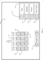
- the monitor system 100 may display a droplet size map 400 as illustrated in FIG. 4 .
- the product application rate map 400 may include a schematic representation of the location of the sprayer10 and its transversely spaced nozzles 20 (e.g., spray nozzles 1-4). It should be appreciated that many more nozzles may be displayed on the rate map than the four nozzles as depicted in FIG. 4 , which is provided for illustration purposes only.
- a map block e.g., map block 428, is placed in the location occupied by each spray nozzle 1-4.
- the pattern, symbol or color of each map block corresponds to a legend 410 preferably displayed in the droplet size map 400.
- the legend 410 preferably includes a set of legend ranges (e.g., legend ranges 412, 414, 416, 418) including, for example, a pattern, symbol or color and a corresponding to droplet size (typically measured in microns). It should be appreciated that the legend ranges 412, 414, 416, 418 correspond to map blocks 422, 424, 426, 428, respectively.
- legend ranges 412, 414, 416, 418 correspond to map blocks 422, 424, 426, 428, respectively.
- the droplet size ranges may include more than the “Fine”, “Medium”, “Course”, “Very Course” ranges depicted in FIG. 4 .
- established droplet size ranges are published by numerous sources which identify droplet size categories including “Extremely Fine”, “Very Fine”, “Fine”, “Medium”, “Course”, “Very Course”, “Extremely Course”, and “Ultra Course”, with each droplet size category having an established range of droplet sizes measured in microns.
- the monitor system 100 may display the product application rate map 400 according to a process designated generally by reference numeral 300 in FIG. 3 .
- the monitor device 110 records the position reported by the GPS receiver 166 and determines the position of each nozzle.
- the monitor device 110 samples the pressure measured by the pressure sensor 162 at the nozzle or in the line associated with the nozzle.
- the monitor device 110 uses the measured pressure sensor signal to derive the droplet size, using algorithms or lookup tables. The algorithms required to calculate droplet size and tables or graphs that identify droplet size for various nozzles at various pressures are well known and thus are not reproduced herein.
- the display device 130 preferably identifies the legend range corresponding to the derived droplet size (e.g., if the droplet size falls within the "Course" category, the display identifies legend range 416).
- the display device 130 displays a map block corresponding to the identified droplet size (e.g., if the droplet size corresponding to 416 is identified, map block 426 is displayed).
- droplet size 400 may be mapped for a section of nozzles 20, such as when a pressure sensor 162 is associated with a gang of nozzles 20A as shown in FIG. 1A .
- one line or hose 11 may supply a plurality of nozzles 20 comprising the gang of nozzles 20A all connected to a pressure sensor 162.
- a plurality of pressure sensors 162 may be averaged together to have a pressure and a resulting droplet size for a gang of nozzles 20A.
- the monitor system 100 may also display a product application rate map 500 an embodiment of which is illustrated in FIG. 5 .
- the product application rate map 500 preferably includes a schematic representation of the location of the sprayer10 and its transversely-spaced nozzles 20 (e.g., nozzles 1-4). It should be appreciated that many more nozzles may be displayed on the droplet size map than the four nozzles as depicted in FIG. 5 , which is provided for illustration purposes only.
- a map block e.g., map block 522
- the pattern, symbol or color of each map block corresponds to a legend 510 preferably displayed in the application rate map 500.
- the legend 510 preferably includes a set of legend ranges (e.g., legend ranges 512, 514, 516) including a pattern, symbol or color and a corresponding application rate range. It should be appreciated, that the application rate ranges may include more than the three ranges depicted in FIG. 5 , which are provided for illustration purposes only.
- the legend ranges 512, 514, 516 correspond to application rates as discussed below. It should be appreciated that the legend ranges 512, 514, 516 correspond to map blocks 522, 524, 526, respectively.
- the application rate map 500 may include an aggregate interface 580 displaying the aggregate application rate (e.g., the application rate over the last 5 seconds) by nozzle and may allow the user to select the nozzle (e.g., nozzle 3 in FIG. 5 ) for which the aggregate application rate is displayed.
- the application rate map 500 may display multiple direction images "D" indicating the direction of the sprayer10.
- the direction images D may be superimposed over or adjacent to one or more map blocks (e.g., map block 522) and indicate the direction of the sprayer 10 at the time the superimposed or adjacent map blocks were placed.
- the monitor system 100 may display the application rate map 500 according to an embodiment of a process designated generally by reference numeral 600 in FIG. 6 .
- the monitor device 110 records the position reported by the GPS receiver 166 and determines the position of each nozzle 20.
- the monitor device 110 samples the pressure measured by the pressure sensor 162 at the nozzle or in the line associated with the nozzle at regular intervals (e.g., one-second intervals).
- the monitor device 110 preferably stores the time of corresponding pressure samples.
- the monitor device 110 preferably determines the nozzle velocity of each nozzle during the first interval (e.g., by averaging all nozzle velocity measurements during the first interval).
- the monitor device 110 assumes the velocity of each nozzle is equal to the speed along the direction of travel reported by a speed sensor 168 mounted to the sprayer 10. In other embodiments, the monitor device 110 calculates a nozzle-specific velocity more accurately (e.g., when executing turns) using one or more speed sensors 168 mounted to the boom 14. At step 620, the monitor device 110 derives the as-applied application rate.
- the product application rate may be derived, using algorithms or lookup tables. The algorithms required to calculate application rates and tables or graphs that identify application rates for various nozzles at various pressures and speeds are well known and thus are not reproduced herein.
- the display device 130 preferably associates the first interval with a map area (e.g., using one or more positions reported by the GPS receiver 166 during the first interval).
- the display device 130 preferably determines the application rate map block to cover the map area associated with the first interval (e.g., a rectangle having a length corresponding to the positions reported by the GPS receiver 166 at the beginning and end of the first interval, and having a width equal to the nozzle spacing).
- each interval is associated with a map block.
- the display device 130 preferably selects an application rate image characteristic (e.g., a pattern, symbol or color) based on the legend range in legend 510 associated with the application rate calculated for the first interval (e.g., application rate map block 522 has a calculated application rate of 5 to 8 gallons per acre and thus has a pattern corresponding to legend range 512).
- the display device 130 preferably displays the application rate map block in the map area associated with the first interval.
- the display device 130 determines the direction of implement travel during the first interval (e.g., by determining the direction of a line between the position during the first interval and the position during a prior interval).
- the display device 130 may display an image (e.g., direction images D in FIG. 5 ) indicating the direction of travel.
- Each direction image may be superimposed over one or more application rate map blocks associated with the first interval. It should be appreciated that the direction images D assist the user in determining which nozzle sprayed an area when reviewing the map after spraying operations.
- a process for displaying linked maps of agricultural data is illustrated generally by reference numeral 1900 in FIG. 12 .
- the display device 130 preferably accesses aerial image map tiles corresponding to a location.
- the display device 130 preferably accesses first and second sets of agricultural data. Each set of agricultural data preferably comprises agricultural data associated with geo-referenced locations such that a spatial map may be generated therefrom.
- the display device 130 preferably generates a first map overlay corresponding to the first set of agricultural data and a second map overlay corresponding to the second set of agricultural data.
- the display device 130 preferably displays a first map comprising the first map overlay, preferably superimposed over a first aerial image map.
- the display device 130 preferably displays a second map comprising the second map overlay, preferably superimposed over a second aerial image map.
- the second map preferably has a view characteristic (e.g., orientation, scale, zoom level or center) equal to the same view characteristic of the first map.
- the second map preferably has multiple view characteristics equal to the same view characteristics of the first map.
- the second map is preferably at least partly disjoined from the first map (e.g., the second map may be displayed side-by-side with the first map).
- the display device 130 preferably displays a first annotation on the first map and a second annotation on the second map. Both the first annotation and second annotation preferably correspond to the same geo-referenced location such that a user may reference the annotation to visually determine corresponding locations on the first and second maps.
- the display device 130 preferably receives and implements a user command to apply a first modification to a view characteristic of the first map.
- the user command comprises a manipulation of a user interface displayed on the map (e.g., adjustment of a scale to adjust zoom level).
- the user command comprises a manipulation of a touch screen of the display (e.g., "pinching" the touch screen to adjust zoom level).
- the display device 130 upon determining that a modification has been made to the first map, the display device 130 preferably matches the visible area and zoom level of the second map to the visible area and zoom level of the first map.
- the display device 130 preferably matches the visible area of the second map to the visible area the first map by determining the geo-referenced locations corresponding to a boundary of the first map and then re-drawing the second map such that a boundary of the second map corresponds to the same geo-referenced locations.
- the display device 130 applies a second modification to the second map corresponding to the first modification and preferably applies the second modification to the same view characteristic as the first modification. For example, if the first modification comprises rotation of the first map about a first angle, then the second modification preferably comprises rotation of the second map about the first angle.
- the display device 130 preferably receives and implements a user command to apply a modification to a view characteristic of the second map.
- the display device 130 preferably matches the visible area and zoom level of the first map to the visible area and zoom level of the second map.
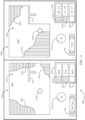
- the map screen 1500 preferably includes a live spraying map window 1550 and a prior season spraying map window 1560.
- the live spraying map window 1550 preferably displays a map overlay 1555 comprised of map blocks 1522, 1524, 1526 representing live spraying data (e.g., application rate) associated with the location of the block.
- live spraying data e.g., application rate
- the pattern, symbol or color of each map block corresponds to a legend 1510 preferably displayed in the live spraying map window 1550.
- the legend 1510 preferably includes a set of legend ranges (e.g., legend ranges 1512, 1514, 1516) including a pattern, symbol or color and a corresponding value range.
- the legend ranges 1512, 1514, 1516 correspond to application rate ranges. It should be appreciated that the legend ranges 1512, 1514, 1516 correspond to map blocks 1522, 1524, 1526, respectively.
- a boundary 1580-1 preferably defines the extent of the map being displayed. The boundary 1580-1 preferably remains in the same position with respect to the borders of the live spraying map window 1550.
- the boundary 1580-1 is coextensive with the borders of the live spraying map window 1550.
- An orientation indicator 1575-1 preferably indicates the current orientation of the map layer 1555. When the map layer 1555 is rotated, the orientation indicator 1575-1 preferably updates to display the orientation of the map layer with respect to north.
- An annotation 1570-1 preferably remains at the same position with respect to the boundary 1580-1 as the map layer 1555 is manipulated.
- the prior season spray map window 1560 preferably displays a prior season spraying data map overlay 1565 comprised of map polygons 1542, 1544, 1546 representing spraying data (e.g., application rates) from a prior season.
- the pattern, symbol or color of each map polygon corresponds to a legend 1530 preferably displayed in the prior season spray map window 1560.
- the legend 1530 preferably includes a set of legend ranges (e.g., legend ranges 1532, 1534, 1536) including a pattern, symbol or color and a corresponding value range.
- the legend ranges 1512, 1514, 1516 correspond to application ranges.
- a boundary 1580-2 preferably defines the extent of the map being displayed.
- the boundary 1580-2 preferably remains in the same position with respect to the borders of the live spraying map window 1550. In some embodiments the boundary 1580-2 is coextensive with the borders of the live spraying map window 1550.
- the boundaries 1580-1, 1580-2 preferably correspond to the same set of geo-referenced coordinates.
- An orientation indicator 1575-2 preferably indicates the current orientation of the map layer 1565. When the map layer 1565 is rotated, the orientation indicator 1575-2 preferably updates to display the orientation of the map layer with respect to north.
- An annotation 1570-2 preferably remains at the same position with respect to the boundary 1580-2 as the map layer 1565 is manipulated.
- the annotations 1570-1,1570-2 preferably correspond to the same geo-referenced location (e.g., the same GPS coordinates) such that a user may use the annotations as a point of reference to compare corresponding locations on the map layers 1555, 1565.
- the map screen 1600 preferably includes a completed spray map window 1650 and a live yield map window 1660.
- the completed spray map window 1650 is preferably similar to the live spray map window of FIG. 8 , except that the data has been completed in a prior spraying operation and is obtained from a file stored in memory.
- the live yield map window 1660 preferably includes a map layer 1665 comprising yield map polygons 1632, 1634, 1636 (or blocks similar to those used in the spray maps described herein) corresponding to ranges 1622, 1624, 1626 of a yield legend 1620.
- a combine annotation 12 indicates the current location of the combine within the map.
- the map screen 1700 preferably includes an input application window 1750 and a live yield map window 1660 substantially similar to the live yield map window 1660 in the map screen 1600 of FIG. 9 .
- the input application window 1750 preferably displays a map layer 1755 representing spatially varying rate of application of a crop input; in the illustrated embodiment, the map layer 1755 represents the rate of application of nitrogen.
- the map layer 1755 preferably comprises a set of application rate polygons 1722, 1724, 1726 corresponding to legend ranges 1712, 1714, 1716 of an application rate legend 1710.
- the data used to generate the map layer 1755 may be accessed from a memory outside the monitor system 100. For example, nitrogen application rate data may be transferred (e.g., via a portable memory) from a desktop computer used to generate a nitrogen application prescription or a nitrogen application monitor system used to control and record as-applied nitrogen application.
- the map screen 1800 preferably includes a soil type window 1850 and a live yield map window 1660 substantially similar to the live yield map window 1660 in the map screen 1600 of FIG. 9 .
- the soil type window 1850 preferably displays a map layer 1855 representing spatially soil types in the field.
- the map layer 1855 preferably comprises a set of soil type polygons 1822, 1824, 1826 corresponding to legend ranges 1812, 1814, 1816 of an soil type legend 1810.
- a combine annotation 12b is preferably displayed in the soil type window 1850; as the combine traverses the field, the display device 130 preferably updates the location of the combine annotation 12b such that the combine annotation 12b is displayed at the location on the map layer 1855 corresponding to the same geo-referenced location as the current location of the combine annotation 12 on the map layer 1665.
- Components described herein as being in electrical communication may be in data communication via any suitable device or devices.
- the term "data communication” as used herein is intended to encompass wireless (e.g., radio-based), electrical, electronic, and other forms of digital or analog data transmission.
- Components described herein as being in communication via a harness may be in data communication via any suitable device or devices.
- a harness may comprise a single electrical line or a bundled plurality of electrical lines, and may comprise a point-to-point connection or a bus.
Landscapes
- Life Sciences & Earth Sciences (AREA)
- Environmental Sciences (AREA)
- Engineering & Computer Science (AREA)
- Insects & Arthropods (AREA)
- Pest Control & Pesticides (AREA)
- Wood Science & Technology (AREA)
- Zoology (AREA)
- Soil Sciences (AREA)
- Mechanical Engineering (AREA)
- Management, Administration, Business Operations System, And Electronic Commerce (AREA)
- Catching Or Destruction (AREA)
- Application Of Or Painting With Fluid Materials (AREA)
Claims (15)
- Procédé de cartographie graphique de l'application de produit liquide dans un champ par un pulvérisateur agricole (10) comportant une pluralité d'injecteurs de pulvérisation (20), le procédé comprenant :le contrôle des positions géographiques (305) de chacun de la pluralité d'injecteurs de pulvérisation (20) lorsque le pulvérisateur agricole (10) traverse le champ ;la mesure de la pression (308) à intervalles de temps réguliers au niveau de chacun de la pluralité d'injecteurs de pulvérisation (20) ou sur une ligne associée à un groupe d'injecteurs (20A) lorsque le pulvérisateur agricole traverse le champ ;la déduction d'une taille de gouttelettes du produit liquide pulvérisé par chacun de la pluralité d'injecteurs de pulvérisation (20) ou dudit groupe d'injecteurs de pulvérisation (20A) sur la base de ladite pression mesurée et des caractéristiques d'injecteur prédéfinies de chacun de ladite pluralité d'injecteurs de pulvérisation ;la production d'une carte d'application sur une image aérienne du champ, la carte d'application comportant une carte de taille de gouttelettes (400) montrant lesdites tailles de gouttelettes pulvérisées par chacun de la pluralité d'injecteurs de pulvérisation (20) ou dudit groupe d'injecteurs de pulvérisation (20A) lorsque le pulvérisateur agricole traverse le champ.
- Procédé selon la revendication 1, dans lequel ladite carte d'application telle que réalisée comporte une représentation schématique d'une position du pulvérisateur agricole (10) et de ladite pluralité d'injecteurs (20) lorsque le pulvérisateur agricole (10) traverse le champ.
- Procédé selon la revendication 2, dans lequel ladite carte de taille de gouttelettes (400) comporte un bloc de carte de gouttelettes (422, 424, 426, 428) placé à une position occupée par chacun de ladite pluralité d'injecteurs de pulvérisation (20) lorsque le pulvérisateur agricole (10) traverse le champ.
- Procédé selon la revendication 3, dans lequel chacun desdits blocs de carte de gouttelettes (422, 424, 426, 428) correspond à une plage de taille de gouttelettes (412, 414, 416, 418).
- Procédé selon la revendication 4, dans lequel chacune desdites plages de taille de gouttelettes (412, 414, 416, 418) est représentée par un motif, un symbole ou une couleur.
- Procédé selon la revendication 5, dans lequel ladite carte de taille de gouttelettes (400) comporte une légende (410) associant chacun desdits motifs, symboles ou couleurs à chacune desdites plages de taille de gouttelettes (412, 414, 416, 418).
- Procédé selon la revendication 1, comprenant, en outre :la détermination d'une vitesse d'injecteur de chacun des injecteurs (20) du pulvérisateur agricole (10) ;la déduction d'un débit d'application du produit liquide pulvérisé par chacun de la pluralité d'injecteurs de pulvérisation (20) ou dudit groupe d'injecteurs de pulvérisation (20A) sur la base de ladite pression mesurée et de ladite vitesse d'injecteur ;dans lequel ladite carte d'application comporte une carte de débit d'application (500) montrant lesdits débits d'application pulvérisés par chacun de la pluralité d'injecteurs de pulvérisation (20) ou dudit groupe d'injecteurs de pulvérisation (20A) lorsque le pulvérisateur agricole (10) traverse le champ.
- Procédé selon la revendication 7, dans lequel ladite étape de détermination de la vitesse d'injecteur est basée sur une vitesse mesurée du pulvérisateur agricole (10).
- Procédé selon la revendication 7, dans lequel ladite étape de détermination de vitesse d'injecteur est déterminée en utilisant des capteurs de vitesse (168) montés sur le pulvérisateur (10).
- Procédé selon la revendication 7, dans lequel ladite carte de débit d'application (500) comporte une représentation schématique d'une position du pulvérisateur agricole (10) et de ladite pluralité d'injecteurs (20) lorsque le pulvérisateur agricole (10) traverse le champ.
- Procédé selon la revendication 10, dans lequel ladite carte de débit d'application (500) comporte un bloc de carte de débit d'application (522, 524, 526) placé dans une position occupée par chacun de ladite pluralité d'injecteurs de pulvérisation (20) lorsque le pulvérisateur agricole traverse le champ.
- Procédé selon la revendication 11, dans lequel chacun desdits blocs de carte de débit d'application (522, 524, 526) correspond à une plage de débit d'application (512, 514, 516).
- Procédé selon la revendication 12, dans lequel chacune desdites plages de débit d'application (512, 514, 516) est représentée par un motif, un symbole ou une couleur.
- Procédé selon la revendication 13, dans lequel ladite carte de débit d'application (500) comporte une légende (510) associant chacun desdits motifs, symboles ou couleurs à chacune desdites plages de débit d'application (512, 514, 516).
- Procédé selon la revendication 1, dans lequel les injecteurs de pulvérisation (20) sont configurés avec des actionneurs permettant la sélection de différentes tailles de gouttelettes d'injecteur.
Applications Claiming Priority (2)
| Application Number | Priority Date | Filing Date | Title |
|---|---|---|---|
| US201862622792P | 2018-01-26 | 2018-01-26 | |
| PCT/US2019/015476 WO2019148138A1 (fr) | 2018-01-26 | 2019-01-28 | Procédé de mappage de taille de gouttelettes de pulvérisateurs agricoles |
Publications (3)
| Publication Number | Publication Date |
|---|---|
| EP3742882A1 EP3742882A1 (fr) | 2020-12-02 |
| EP3742882A4 EP3742882A4 (fr) | 2021-10-20 |
| EP3742882B1 true EP3742882B1 (fr) | 2023-10-18 |
Family
ID=67396220
Family Applications (1)
| Application Number | Title | Priority Date | Filing Date |
|---|---|---|---|
| EP19743544.9A Active EP3742882B1 (fr) | 2018-01-26 | 2019-01-28 | Procédé de cartographie de la taille de gouttelettes de pulvérisateurs agricoles |
Country Status (10)
| Country | Link |
|---|---|
| US (1) | US11903378B2 (fr) |
| EP (1) | EP3742882B1 (fr) |
| CN (1) | CN111601496B (fr) |
| AR (1) | AR114322A1 (fr) |
| AU (1) | AU2019212971B2 (fr) |
| CA (1) | CA3084995A1 (fr) |
| RU (1) | RU2020128325A (fr) |
| UA (1) | UA126824C2 (fr) |
| WO (1) | WO2019148138A1 (fr) |
| ZA (1) | ZA202003370B (fr) |
Cited By (1)
| Publication number | Priority date | Publication date | Assignee | Title |
|---|---|---|---|---|
| WO2025093203A1 (fr) * | 2023-11-02 | 2025-05-08 | Ecorobotix Sa | Pulvérisation localisée efficace de produits agrochimiques |
Families Citing this family (12)
| Publication number | Priority date | Publication date | Assignee | Title |
|---|---|---|---|---|
| FR3110322B1 (fr) * | 2020-05-20 | 2024-09-20 | Nadir Ghrous | gestion du dosage d’intrants à appliquer sur une surface agricole |
| US11844298B2 (en) | 2020-02-12 | 2023-12-19 | Alvie 1 | Management of the dosing of inputs to be applied to an agricultural surface |
| CA3165727A1 (fr) * | 2020-04-03 | 2021-10-07 | Precision Planting Llc | Systemes et procedes agricoles |
| CA3174976A1 (fr) * | 2020-04-16 | 2021-10-21 | Flavio CENTOLA | Procedes et algorithmes pour optimiser l'application de produits phytosanitaires a residus limites en utilisant une application a taux variable |
| US12120977B2 (en) * | 2020-10-15 | 2024-10-22 | Topcon Positioning Systems, Inc. | Method and apparatus for controlling nozzle flow rates |
| CA3195070A1 (fr) * | 2020-10-26 | 2022-05-05 | Precision Planting Llc | Outil a conduite automatisee |
| US12056921B2 (en) | 2020-10-30 | 2024-08-06 | Deere & Company | Diagnostic system visualization and control for an agricultural spraying machine |
| US11998000B2 (en) | 2020-10-30 | 2024-06-04 | Deere & Company | Camera system visualization and control for an agricultural spraying machine |
| US12010986B2 (en) | 2020-10-30 | 2024-06-18 | Deere & Company | Agricultural machine spraying mode field map visualization and control |
| US20230039178A1 (en) * | 2021-08-03 | 2023-02-09 | Cnh Industrial America Llc | System and method for controlling nozzle operation of an agricultural sprayer |
| EP4173482A1 (fr) * | 2021-10-29 | 2023-05-03 | Kverneland Group Nieuw-Vennep BV | Procédé de fonctionnement d'un épandeur agricole et épandeur agricole |
| US12541872B2 (en) | 2021-11-12 | 2026-02-03 | Raven Industries, Inc. | Determination of droplet characteristics |
Family Cites Families (8)
| Publication number | Priority date | Publication date | Assignee | Title |
|---|---|---|---|---|
| US5704546A (en) | 1995-09-15 | 1998-01-06 | Captstan, Inc. | Position-responsive control system and method for sprayer |
| US5884205A (en) | 1996-08-22 | 1999-03-16 | Dickey-John Corporation | Boom configuration monitoring and control system for mobile material distribution apparatus |
| CN104954596B (zh) * | 2011-07-25 | 2018-03-30 | 株式会社久保田 | 作业机以及作业机的设定变更系统 |
| US20130105591A1 (en) | 2011-10-28 | 2013-05-02 | Agco Corporation | Drift plume display |
| AU2013299359B2 (en) * | 2012-08-10 | 2018-09-20 | Climate Llc | Systems and methods for control, monitoring and mapping of agricultural applications |
| KR20190138705A (ko) * | 2013-04-26 | 2019-12-13 | 카티바, 인크. | 인쇄 잉크 액적 측정 및 정밀 공차 내로 유체를 증착하기 위한 제어 기법 |
| US9717178B1 (en) | 2014-08-08 | 2017-08-01 | The Climate Corporation | Systems and method for monitoring, controlling, and displaying field operations |
| EP3072376A3 (fr) * | 2015-03-26 | 2016-11-23 | Basf Se | Procédé et véhicule permettant d'appliquer un mélange agrochimique jusqu'à une zone de travail d'un champ |
-
2019
- 2019-01-28 WO PCT/US2019/015476 patent/WO2019148138A1/fr not_active Ceased
- 2019-01-28 UA UAA202004731A patent/UA126824C2/uk unknown
- 2019-01-28 AU AU2019212971A patent/AU2019212971B2/en active Active
- 2019-01-28 US US16/965,257 patent/US11903378B2/en active Active
- 2019-01-28 CN CN201980008390.8A patent/CN111601496B/zh not_active Expired - Fee Related
- 2019-01-28 CA CA3084995A patent/CA3084995A1/fr active Pending
- 2019-01-28 EP EP19743544.9A patent/EP3742882B1/fr active Active
- 2019-01-28 AR ARP190100189A patent/AR114322A1/es active IP Right Grant
- 2019-01-28 RU RU2020128325A patent/RU2020128325A/ru unknown
-
2020
- 2020-06-05 ZA ZA2020/03370A patent/ZA202003370B/en unknown
Cited By (1)
| Publication number | Priority date | Publication date | Assignee | Title |
|---|---|---|---|---|
| WO2025093203A1 (fr) * | 2023-11-02 | 2025-05-08 | Ecorobotix Sa | Pulvérisation localisée efficace de produits agrochimiques |
Also Published As
| Publication number | Publication date |
|---|---|
| US11903378B2 (en) | 2024-02-20 |
| CN111601496A (zh) | 2020-08-28 |
| EP3742882A1 (fr) | 2020-12-02 |
| CA3084995A1 (fr) | 2019-08-01 |
| AR114322A1 (es) | 2020-08-19 |
| WO2019148138A1 (fr) | 2019-08-01 |
| RU2020128325A3 (fr) | 2022-04-18 |
| AU2019212971B2 (en) | 2024-11-07 |
| UA126824C2 (uk) | 2023-02-08 |
| AU2019212971A1 (en) | 2020-06-25 |
| BR112020011516A2 (pt) | 2020-11-17 |
| CN111601496B (zh) | 2023-05-05 |
| EP3742882A4 (fr) | 2021-10-20 |
| ZA202003370B (en) | 2024-02-28 |
| RU2020128325A (ru) | 2022-02-28 |
| US20210068384A1 (en) | 2021-03-11 |
Similar Documents
| Publication | Publication Date | Title |
|---|---|---|
| EP3742882B1 (fr) | Procédé de cartographie de la taille de gouttelettes de pulvérisateurs agricoles | |
| US11596964B2 (en) | System for spraying plants with automated nozzle selection | |
| EP3927157B1 (fr) | Machine agricole et procédé pour disperser un liquide | |
| EP3482619B1 (fr) | Procédé de traitement de plantes par rapport aux zones de racine estimées | |
| US12239123B2 (en) | Systems and methods for spraying an agricultural fluid on foliage | |
| EP3888458B1 (fr) | Application de pulvérisation ciblée pour protéger les cultures | |
| EP3476216B1 (fr) | Procédé de traitement de plantes par rapport aux zones de racine estimées | |
| US6708080B2 (en) | Method for dispensing an agricultural product | |
| US6216614B1 (en) | Boom dispensing point control system | |
| Penzotti et al. | A planning strategy for sprinkler-based variable rate irrigation | |
| EP4228390B1 (fr) | Procédé et appareil pour cartographier une zone | |
| BR112020011516B1 (pt) | Método de mapear tamanho de gotículas de pulverizadores agrícolas | |
| RU2807221C2 (ru) | Сельскохозяйственное устройство и способ дозирования жидкости | |
| WO2024074674A1 (fr) | Moteur de choix de buse | |
| CA2450822C (fr) | Regulation et suivi de l'epandage d'un produit agricole |
Legal Events
| Date | Code | Title | Description |
|---|---|---|---|
| STAA | Information on the status of an ep patent application or granted ep patent |
Free format text: STATUS: THE INTERNATIONAL PUBLICATION HAS BEEN MADE |
|
| PUAI | Public reference made under article 153(3) epc to a published international application that has entered the european phase |
Free format text: ORIGINAL CODE: 0009012 |
|
| STAA | Information on the status of an ep patent application or granted ep patent |
Free format text: STATUS: REQUEST FOR EXAMINATION WAS MADE |
|
| 17P | Request for examination filed |
Effective date: 20200826 |
|
| AK | Designated contracting states |
Kind code of ref document: A1 Designated state(s): AL AT BE BG CH CY CZ DE DK EE ES FI FR GB GR HR HU IE IS IT LI LT LU LV MC MK MT NL NO PL PT RO RS SE SI SK SM TR |
|
| AX | Request for extension of the european patent |
Extension state: BA ME |
|
| DAV | Request for validation of the european patent (deleted) | ||
| DAX | Request for extension of the european patent (deleted) | ||
| A4 | Supplementary search report drawn up and despatched |
Effective date: 20210921 |
|
| RIC1 | Information provided on ipc code assigned before grant |
Ipc: A01M 7/00 20060101ALI20210915BHEP Ipc: A01B 79/00 20060101ALI20210915BHEP Ipc: A01C 23/00 20060101AFI20210915BHEP |
|
| P01 | Opt-out of the competence of the unified patent court (upc) registered |
Effective date: 20230518 |
|
| GRAP | Despatch of communication of intention to grant a patent |
Free format text: ORIGINAL CODE: EPIDOSNIGR1 |
|
| STAA | Information on the status of an ep patent application or granted ep patent |
Free format text: STATUS: GRANT OF PATENT IS INTENDED |
|
| RIC1 | Information provided on ipc code assigned before grant |
Ipc: A01C 21/00 20060101ALN20230627BHEP Ipc: A01M 7/00 20060101ALI20230627BHEP Ipc: A01C 23/00 20060101AFI20230627BHEP |
|
| INTG | Intention to grant announced |
Effective date: 20230725 |
|
| GRAS | Grant fee paid |
Free format text: ORIGINAL CODE: EPIDOSNIGR3 |
|
| GRAA | (expected) grant |
Free format text: ORIGINAL CODE: 0009210 |
|
| STAA | Information on the status of an ep patent application or granted ep patent |
Free format text: STATUS: THE PATENT HAS BEEN GRANTED |
|
| AK | Designated contracting states |
Kind code of ref document: B1 Designated state(s): AL AT BE BG CH CY CZ DE DK EE ES FI FR GB GR HR HU IE IS IT LI LT LU LV MC MK MT NL NO PL PT RO RS SE SI SK SM TR |
|
| REG | Reference to a national code |
Ref country code: GB Ref legal event code: FG4D |
|
| REG | Reference to a national code |
Ref country code: CH Ref legal event code: EP |
|
| REG | Reference to a national code |
Ref country code: IE Ref legal event code: FG4D |
|
| REG | Reference to a national code |
Ref country code: DE Ref legal event code: R096 Ref document number: 602019039610 Country of ref document: DE |
|
| REG | Reference to a national code |
Ref country code: LT Ref legal event code: MG9D |
|
| REG | Reference to a national code |
Ref country code: NL Ref legal event code: MP Effective date: 20231018 |
|
| REG | Reference to a national code |
Ref country code: AT Ref legal event code: MK05 Ref document number: 1621565 Country of ref document: AT Kind code of ref document: T Effective date: 20231018 |
|
| PG25 | Lapsed in a contracting state [announced via postgrant information from national office to epo] |
Ref country code: NL Free format text: LAPSE BECAUSE OF FAILURE TO SUBMIT A TRANSLATION OF THE DESCRIPTION OR TO PAY THE FEE WITHIN THE PRESCRIBED TIME-LIMIT Effective date: 20231018 |
|
| PG25 | Lapsed in a contracting state [announced via postgrant information from national office to epo] |
Ref country code: GR Free format text: LAPSE BECAUSE OF FAILURE TO SUBMIT A TRANSLATION OF THE DESCRIPTION OR TO PAY THE FEE WITHIN THE PRESCRIBED TIME-LIMIT Effective date: 20240119 |
|
| PG25 | Lapsed in a contracting state [announced via postgrant information from national office to epo] |
Ref country code: IS Free format text: LAPSE BECAUSE OF FAILURE TO SUBMIT A TRANSLATION OF THE DESCRIPTION OR TO PAY THE FEE WITHIN THE PRESCRIBED TIME-LIMIT Effective date: 20240218 |
|
| PG25 | Lapsed in a contracting state [announced via postgrant information from national office to epo] |
Ref country code: LT Free format text: LAPSE BECAUSE OF FAILURE TO SUBMIT A TRANSLATION OF THE DESCRIPTION OR TO PAY THE FEE WITHIN THE PRESCRIBED TIME-LIMIT Effective date: 20231018 |
|
| PG25 | Lapsed in a contracting state [announced via postgrant information from national office to epo] |
Ref country code: AT Free format text: LAPSE BECAUSE OF FAILURE TO SUBMIT A TRANSLATION OF THE DESCRIPTION OR TO PAY THE FEE WITHIN THE PRESCRIBED TIME-LIMIT Effective date: 20231018 |
|
| PG25 | Lapsed in a contracting state [announced via postgrant information from national office to epo] |
Ref country code: ES Free format text: LAPSE BECAUSE OF FAILURE TO SUBMIT A TRANSLATION OF THE DESCRIPTION OR TO PAY THE FEE WITHIN THE PRESCRIBED TIME-LIMIT Effective date: 20231018 |
|
| PG25 | Lapsed in a contracting state [announced via postgrant information from national office to epo] |
Ref country code: LT Free format text: LAPSE BECAUSE OF FAILURE TO SUBMIT A TRANSLATION OF THE DESCRIPTION OR TO PAY THE FEE WITHIN THE PRESCRIBED TIME-LIMIT Effective date: 20231018 Ref country code: IS Free format text: LAPSE BECAUSE OF FAILURE TO SUBMIT A TRANSLATION OF THE DESCRIPTION OR TO PAY THE FEE WITHIN THE PRESCRIBED TIME-LIMIT Effective date: 20240218 Ref country code: GR Free format text: LAPSE BECAUSE OF FAILURE TO SUBMIT A TRANSLATION OF THE DESCRIPTION OR TO PAY THE FEE WITHIN THE PRESCRIBED TIME-LIMIT Effective date: 20240119 Ref country code: ES Free format text: LAPSE BECAUSE OF FAILURE TO SUBMIT A TRANSLATION OF THE DESCRIPTION OR TO PAY THE FEE WITHIN THE PRESCRIBED TIME-LIMIT Effective date: 20231018 Ref country code: BG Free format text: LAPSE BECAUSE OF FAILURE TO SUBMIT A TRANSLATION OF THE DESCRIPTION OR TO PAY THE FEE WITHIN THE PRESCRIBED TIME-LIMIT Effective date: 20240118 Ref country code: AT Free format text: LAPSE BECAUSE OF FAILURE TO SUBMIT A TRANSLATION OF THE DESCRIPTION OR TO PAY THE FEE WITHIN THE PRESCRIBED TIME-LIMIT Effective date: 20231018 Ref country code: PT Free format text: LAPSE BECAUSE OF FAILURE TO SUBMIT A TRANSLATION OF THE DESCRIPTION OR TO PAY THE FEE WITHIN THE PRESCRIBED TIME-LIMIT Effective date: 20240219 |
|
| PG25 | Lapsed in a contracting state [announced via postgrant information from national office to epo] |
Ref country code: SE Free format text: LAPSE BECAUSE OF FAILURE TO SUBMIT A TRANSLATION OF THE DESCRIPTION OR TO PAY THE FEE WITHIN THE PRESCRIBED TIME-LIMIT Effective date: 20231018 Ref country code: RS Free format text: LAPSE BECAUSE OF FAILURE TO SUBMIT A TRANSLATION OF THE DESCRIPTION OR TO PAY THE FEE WITHIN THE PRESCRIBED TIME-LIMIT Effective date: 20231018 Ref country code: PL Free format text: LAPSE BECAUSE OF FAILURE TO SUBMIT A TRANSLATION OF THE DESCRIPTION OR TO PAY THE FEE WITHIN THE PRESCRIBED TIME-LIMIT Effective date: 20231018 Ref country code: NO Free format text: LAPSE BECAUSE OF FAILURE TO SUBMIT A TRANSLATION OF THE DESCRIPTION OR TO PAY THE FEE WITHIN THE PRESCRIBED TIME-LIMIT Effective date: 20240118 Ref country code: LV Free format text: LAPSE BECAUSE OF FAILURE TO SUBMIT A TRANSLATION OF THE DESCRIPTION OR TO PAY THE FEE WITHIN THE PRESCRIBED TIME-LIMIT Effective date: 20231018 Ref country code: HR Free format text: LAPSE BECAUSE OF FAILURE TO SUBMIT A TRANSLATION OF THE DESCRIPTION OR TO PAY THE FEE WITHIN THE PRESCRIBED TIME-LIMIT Effective date: 20231018 |
|
| PG25 | Lapsed in a contracting state [announced via postgrant information from national office to epo] |
Ref country code: DK Free format text: LAPSE BECAUSE OF FAILURE TO SUBMIT A TRANSLATION OF THE DESCRIPTION OR TO PAY THE FEE WITHIN THE PRESCRIBED TIME-LIMIT Effective date: 20231018 |
|
| REG | Reference to a national code |
Ref country code: DE Ref legal event code: R097 Ref document number: 602019039610 Country of ref document: DE |
|
| PG25 | Lapsed in a contracting state [announced via postgrant information from national office to epo] |
Ref country code: CZ Free format text: LAPSE BECAUSE OF FAILURE TO SUBMIT A TRANSLATION OF THE DESCRIPTION OR TO PAY THE FEE WITHIN THE PRESCRIBED TIME-LIMIT Effective date: 20231018 |
|
| PG25 | Lapsed in a contracting state [announced via postgrant information from national office to epo] |
Ref country code: SK Free format text: LAPSE BECAUSE OF FAILURE TO SUBMIT A TRANSLATION OF THE DESCRIPTION OR TO PAY THE FEE WITHIN THE PRESCRIBED TIME-LIMIT Effective date: 20231018 |
|
| PG25 | Lapsed in a contracting state [announced via postgrant information from national office to epo] |
Ref country code: SM Free format text: LAPSE BECAUSE OF FAILURE TO SUBMIT A TRANSLATION OF THE DESCRIPTION OR TO PAY THE FEE WITHIN THE PRESCRIBED TIME-LIMIT Effective date: 20231018 Ref country code: SK Free format text: LAPSE BECAUSE OF FAILURE TO SUBMIT A TRANSLATION OF THE DESCRIPTION OR TO PAY THE FEE WITHIN THE PRESCRIBED TIME-LIMIT Effective date: 20231018 Ref country code: RO Free format text: LAPSE BECAUSE OF FAILURE TO SUBMIT A TRANSLATION OF THE DESCRIPTION OR TO PAY THE FEE WITHIN THE PRESCRIBED TIME-LIMIT Effective date: 20231018 Ref country code: IT Free format text: LAPSE BECAUSE OF FAILURE TO SUBMIT A TRANSLATION OF THE DESCRIPTION OR TO PAY THE FEE WITHIN THE PRESCRIBED TIME-LIMIT Effective date: 20231018 Ref country code: EE Free format text: LAPSE BECAUSE OF FAILURE TO SUBMIT A TRANSLATION OF THE DESCRIPTION OR TO PAY THE FEE WITHIN THE PRESCRIBED TIME-LIMIT Effective date: 20231018 Ref country code: DK Free format text: LAPSE BECAUSE OF FAILURE TO SUBMIT A TRANSLATION OF THE DESCRIPTION OR TO PAY THE FEE WITHIN THE PRESCRIBED TIME-LIMIT Effective date: 20231018 Ref country code: CZ Free format text: LAPSE BECAUSE OF FAILURE TO SUBMIT A TRANSLATION OF THE DESCRIPTION OR TO PAY THE FEE WITHIN THE PRESCRIBED TIME-LIMIT Effective date: 20231018 |
|
| PLBE | No opposition filed within time limit |
Free format text: ORIGINAL CODE: 0009261 |
|
| STAA | Information on the status of an ep patent application or granted ep patent |
Free format text: STATUS: NO OPPOSITION FILED WITHIN TIME LIMIT |
|
| PG25 | Lapsed in a contracting state [announced via postgrant information from national office to epo] |
Ref country code: MC Free format text: LAPSE BECAUSE OF FAILURE TO SUBMIT A TRANSLATION OF THE DESCRIPTION OR TO PAY THE FEE WITHIN THE PRESCRIBED TIME-LIMIT Effective date: 20231018 |
|
| PG25 | Lapsed in a contracting state [announced via postgrant information from national office to epo] |
Ref country code: MC Free format text: LAPSE BECAUSE OF FAILURE TO SUBMIT A TRANSLATION OF THE DESCRIPTION OR TO PAY THE FEE WITHIN THE PRESCRIBED TIME-LIMIT Effective date: 20231018 |
|
| REG | Reference to a national code |
Ref country code: CH Ref legal event code: PL |
|
| PG25 | Lapsed in a contracting state [announced via postgrant information from national office to epo] |
Ref country code: LU Free format text: LAPSE BECAUSE OF NON-PAYMENT OF DUE FEES Effective date: 20240128 |
|
| 26N | No opposition filed |
Effective date: 20240719 |
|
| GBPC | Gb: european patent ceased through non-payment of renewal fee |
Effective date: 20240128 |
|
| PG25 | Lapsed in a contracting state [announced via postgrant information from national office to epo] |
Ref country code: LU Free format text: LAPSE BECAUSE OF NON-PAYMENT OF DUE FEES Effective date: 20240128 |
|
| PG25 | Lapsed in a contracting state [announced via postgrant information from national office to epo] |
Ref country code: GB Free format text: LAPSE BECAUSE OF NON-PAYMENT OF DUE FEES Effective date: 20240128 |
|
| PG25 | Lapsed in a contracting state [announced via postgrant information from national office to epo] |
Ref country code: BE Free format text: LAPSE BECAUSE OF NON-PAYMENT OF DUE FEES Effective date: 20240131 |
|
| PG25 | Lapsed in a contracting state [announced via postgrant information from national office to epo] |
Ref country code: CH Free format text: LAPSE BECAUSE OF NON-PAYMENT OF DUE FEES Effective date: 20240131 |
|
| PG25 | Lapsed in a contracting state [announced via postgrant information from national office to epo] |
Ref country code: SI Free format text: LAPSE BECAUSE OF FAILURE TO SUBMIT A TRANSLATION OF THE DESCRIPTION OR TO PAY THE FEE WITHIN THE PRESCRIBED TIME-LIMIT Effective date: 20231018 |
|
| PG25 | Lapsed in a contracting state [announced via postgrant information from national office to epo] |
Ref country code: SI Free format text: LAPSE BECAUSE OF FAILURE TO SUBMIT A TRANSLATION OF THE DESCRIPTION OR TO PAY THE FEE WITHIN THE PRESCRIBED TIME-LIMIT Effective date: 20231018 Ref country code: GB Free format text: LAPSE BECAUSE OF NON-PAYMENT OF DUE FEES Effective date: 20240128 Ref country code: CH Free format text: LAPSE BECAUSE OF NON-PAYMENT OF DUE FEES Effective date: 20240131 Ref country code: BE Free format text: LAPSE BECAUSE OF NON-PAYMENT OF DUE FEES Effective date: 20240131 |
|
| REG | Reference to a national code |
Ref country code: BE Ref legal event code: MM Effective date: 20240131 |
|
| PG25 | Lapsed in a contracting state [announced via postgrant information from national office to epo] |
Ref country code: IE Free format text: LAPSE BECAUSE OF NON-PAYMENT OF DUE FEES Effective date: 20240128 |
|
| PG25 | Lapsed in a contracting state [announced via postgrant information from national office to epo] |
Ref country code: IE Free format text: LAPSE BECAUSE OF NON-PAYMENT OF DUE FEES Effective date: 20240128 |
|
| PG25 | Lapsed in a contracting state [announced via postgrant information from national office to epo] |
Ref country code: CY Free format text: LAPSE BECAUSE OF FAILURE TO SUBMIT A TRANSLATION OF THE DESCRIPTION OR TO PAY THE FEE WITHIN THE PRESCRIBED TIME-LIMIT; INVALID AB INITIO Effective date: 20190128 |
|
| PG25 | Lapsed in a contracting state [announced via postgrant information from national office to epo] |
Ref country code: HU Free format text: LAPSE BECAUSE OF FAILURE TO SUBMIT A TRANSLATION OF THE DESCRIPTION OR TO PAY THE FEE WITHIN THE PRESCRIBED TIME-LIMIT; INVALID AB INITIO Effective date: 20190128 |
|
| PG25 | Lapsed in a contracting state [announced via postgrant information from national office to epo] |
Ref country code: FI Free format text: LAPSE BECAUSE OF FAILURE TO SUBMIT A TRANSLATION OF THE DESCRIPTION OR TO PAY THE FEE WITHIN THE PRESCRIBED TIME-LIMIT Effective date: 20231019 |
|
| PG25 | Lapsed in a contracting state [announced via postgrant information from national office to epo] |
Ref country code: TR Free format text: LAPSE BECAUSE OF FAILURE TO SUBMIT A TRANSLATION OF THE DESCRIPTION OR TO PAY THE FEE WITHIN THE PRESCRIBED TIME-LIMIT Effective date: 20231018 |
|
| PGFP | Annual fee paid to national office [announced via postgrant information from national office to epo] |
Ref country code: DE Payment date: 20260121 Year of fee payment: 8 |
|
| PGFP | Annual fee paid to national office [announced via postgrant information from national office to epo] |
Ref country code: FR Payment date: 20260123 Year of fee payment: 8 |