EP3742964B1 - Système sans contact et procédé d'évaluation de la viabilité d'un tissu et d'autres paramètres hémodynamiques - Google Patents
Système sans contact et procédé d'évaluation de la viabilité d'un tissu et d'autres paramètres hémodynamiques Download PDFInfo
- Publication number
- EP3742964B1 EP3742964B1 EP19747421.6A EP19747421A EP3742964B1 EP 3742964 B1 EP3742964 B1 EP 3742964B1 EP 19747421 A EP19747421 A EP 19747421A EP 3742964 B1 EP3742964 B1 EP 3742964B1
- Authority
- EP
- European Patent Office
- Prior art keywords
- tissue
- predetermined
- hemodynamic
- reference signal
- light
- Prior art date
- Legal status (The legal status is an assumption and is not a legal conclusion. Google has not performed a legal analysis and makes no representation as to the accuracy of the status listed.)
- Active
Links
Images




Classifications
-
- A—HUMAN NECESSITIES
- A61—MEDICAL OR VETERINARY SCIENCE; HYGIENE
- A61B—DIAGNOSIS; SURGERY; IDENTIFICATION
- A61B5/00—Measuring for diagnostic purposes; Identification of persons
- A61B5/0059—Measuring for diagnostic purposes; Identification of persons using light, e.g. diagnosis by transillumination, diascopy, fluorescence
- A61B5/0071—Measuring for diagnostic purposes; Identification of persons using light, e.g. diagnosis by transillumination, diascopy, fluorescence by measuring fluorescence emission
-
- A—HUMAN NECESSITIES
- A61—MEDICAL OR VETERINARY SCIENCE; HYGIENE
- A61B—DIAGNOSIS; SURGERY; IDENTIFICATION
- A61B5/00—Measuring for diagnostic purposes; Identification of persons
- A61B5/02—Detecting, measuring or recording for evaluating the cardiovascular system, e.g. pulse, heart rate, blood pressure or blood flow
- A61B5/02028—Determining haemodynamic parameters not otherwise provided for, e.g. cardiac contractility or left ventricular ejection fraction
-
- A—HUMAN NECESSITIES
- A61—MEDICAL OR VETERINARY SCIENCE; HYGIENE
- A61B—DIAGNOSIS; SURGERY; IDENTIFICATION
- A61B5/00—Measuring for diagnostic purposes; Identification of persons
- A61B5/02—Detecting, measuring or recording for evaluating the cardiovascular system, e.g. pulse, heart rate, blood pressure or blood flow
- A61B5/0205—Simultaneously evaluating both cardiovascular conditions and different types of body conditions, e.g. heart and respiratory condition
-
- A—HUMAN NECESSITIES
- A61—MEDICAL OR VETERINARY SCIENCE; HYGIENE
- A61B—DIAGNOSIS; SURGERY; IDENTIFICATION
- A61B5/00—Measuring for diagnostic purposes; Identification of persons
- A61B5/02—Detecting, measuring or recording for evaluating the cardiovascular system, e.g. pulse, heart rate, blood pressure or blood flow
- A61B5/024—Measuring pulse rate or heart rate
- A61B5/02405—Determining heart rate variability
-
- A—HUMAN NECESSITIES
- A61—MEDICAL OR VETERINARY SCIENCE; HYGIENE
- A61B—DIAGNOSIS; SURGERY; IDENTIFICATION
- A61B5/00—Measuring for diagnostic purposes; Identification of persons
- A61B5/02—Detecting, measuring or recording for evaluating the cardiovascular system, e.g. pulse, heart rate, blood pressure or blood flow
- A61B5/026—Measuring blood flow
- A61B5/0261—Measuring blood flow using optical means, e.g. infrared light
-
- A—HUMAN NECESSITIES
- A61—MEDICAL OR VETERINARY SCIENCE; HYGIENE
- A61B—DIAGNOSIS; SURGERY; IDENTIFICATION
- A61B5/00—Measuring for diagnostic purposes; Identification of persons
- A61B5/145—Measuring characteristics of blood in vivo, e.g. gas concentration or pH-value ; Measuring characteristics of body fluids or tissues, e.g. interstitial fluid or cerebral tissue
- A61B5/1455—Measuring characteristics of blood in vivo, e.g. gas concentration or pH-value ; Measuring characteristics of body fluids or tissues, e.g. interstitial fluid or cerebral tissue using optical sensors, e.g. spectral photometrical oximeters
-
- A—HUMAN NECESSITIES
- A61—MEDICAL OR VETERINARY SCIENCE; HYGIENE
- A61B—DIAGNOSIS; SURGERY; IDENTIFICATION
- A61B5/00—Measuring for diagnostic purposes; Identification of persons
- A61B5/44—Detecting, measuring or recording for evaluating the integumentary system, e.g. skin, hair or nails
- A61B5/441—Skin evaluation, e.g. for skin disorder diagnosis
- A61B5/445—Evaluating skin irritation or skin trauma, e.g. rash, eczema, wound, bed sore
-
- A—HUMAN NECESSITIES
- A61—MEDICAL OR VETERINARY SCIENCE; HYGIENE
- A61B—DIAGNOSIS; SURGERY; IDENTIFICATION
- A61B5/00—Measuring for diagnostic purposes; Identification of persons
- A61B5/72—Signal processing specially adapted for physiological signals or for diagnostic purposes
- A61B5/7235—Details of waveform analysis
- A61B5/7253—Details of waveform analysis characterised by using transforms
- A61B5/7257—Details of waveform analysis characterised by using transforms using Fourier transforms
-
- A—HUMAN NECESSITIES
- A61—MEDICAL OR VETERINARY SCIENCE; HYGIENE
- A61B—DIAGNOSIS; SURGERY; IDENTIFICATION
- A61B2560/00—Constructional details of operational features of apparatus; Accessories for medical measuring apparatus
- A61B2560/02—Operational features
- A61B2560/0223—Operational features of calibration, e.g. protocols for calibrating sensors
-
- A—HUMAN NECESSITIES
- A61—MEDICAL OR VETERINARY SCIENCE; HYGIENE
- A61B—DIAGNOSIS; SURGERY; IDENTIFICATION
- A61B5/00—Measuring for diagnostic purposes; Identification of persons
- A61B5/145—Measuring characteristics of blood in vivo, e.g. gas concentration or pH-value ; Measuring characteristics of body fluids or tissues, e.g. interstitial fluid or cerebral tissue
- A61B5/1455—Measuring characteristics of blood in vivo, e.g. gas concentration or pH-value ; Measuring characteristics of body fluids or tissues, e.g. interstitial fluid or cerebral tissue using optical sensors, e.g. spectral photometrical oximeters
- A61B5/14551—Measuring characteristics of blood in vivo, e.g. gas concentration or pH-value ; Measuring characteristics of body fluids or tissues, e.g. interstitial fluid or cerebral tissue using optical sensors, e.g. spectral photometrical oximeters for measuring blood gases
-
- A—HUMAN NECESSITIES
- A61—MEDICAL OR VETERINARY SCIENCE; HYGIENE
- A61B—DIAGNOSIS; SURGERY; IDENTIFICATION
- A61B5/00—Measuring for diagnostic purposes; Identification of persons
- A61B5/145—Measuring characteristics of blood in vivo, e.g. gas concentration or pH-value ; Measuring characteristics of body fluids or tissues, e.g. interstitial fluid or cerebral tissue
- A61B5/1455—Measuring characteristics of blood in vivo, e.g. gas concentration or pH-value ; Measuring characteristics of body fluids or tissues, e.g. interstitial fluid or cerebral tissue using optical sensors, e.g. spectral photometrical oximeters
- A61B5/14551—Measuring characteristics of blood in vivo, e.g. gas concentration or pH-value ; Measuring characteristics of body fluids or tissues, e.g. interstitial fluid or cerebral tissue using optical sensors, e.g. spectral photometrical oximeters for measuring blood gases
- A61B5/14556—Measuring characteristics of blood in vivo, e.g. gas concentration or pH-value ; Measuring characteristics of body fluids or tissues, e.g. interstitial fluid or cerebral tissue using optical sensors, e.g. spectral photometrical oximeters for measuring blood gases by fluorescence
Definitions
- This invention relates to a contactless system and method for assessing tissue viability and other hemodynamic parameters.
- Burn wounds may be classified into four categories of increasing depth: superficial, intermediate partial thickness, deep partial thickness, and full thickness. The latter two classifications typically require aggressive interventions that involve the debridement of necrotic tissue and the application of split thickness skin grafts. These are more morbid wounds typically wrought with the potential for hypertrophic scarring and contractures and may necessitate early surgical excision and grafting to optimize the outcome, See e.g., Ryan et al., Objective Estimates of the Probability of Death From Burn Injuries, N. Engl. J. Med., 1998, 338: 362-6 .
- LPI Laser Doppler Imaging
- ICG Indocyanine green angiography
- LDI has several drawbacks. Because flowmetry requires the probe to directly contact with the burn wound, it may increase the risk of wound infection and may inflict trauma to already vulnerable tissue. See e.g., O'Reilly et al., Laser Doppler Flowmetry Evaluation of Burn Wound Depth, Journal of Bum Care & Research, 1989, Jan. 1; 10(1):1 .
- ICG Indocyanine green
- Conventional Indocyanine green (ICG) video-angiography provides greater skin imaging penetration compared to LDI.
- ICG enables visualization of the deep dermal vasculature using a dye. See e.g., Jerath et al., Burn Wound Assessment in Porcine Skin Using Indocyanine Green Fluorescence, Journal of Trauma and Acute Care Surgery, 1999, Jun 1; 46(b): 1085-8 . is based on the fluorescent properties of the dye being used and quantifying the intensity of the dye.
- ICG provides color-coded maps relative to the perfusion of the investigated area.
- the major drawback associated with conventional ICG video-angiography is that intravascular dye injection is required.
- a contactless system for assessing tissue viability and other hemodynamic parameters includes one or more light sources configured to emit lights at a predetermined wavelength sensitive to hemoglobin concentration associated with spontaneous hemodynamic oscillations at tissue in a predetermined area of a human subject
- One or more polarizers each coupled to one or more of the one or more light sources are configured to polarize the light to a polarized state such that the polarized light in the polarized state diffuses into the tissue in the predetermined area at a predetermined depth and the polarized light is maintained in the polarized state at the predetermined depth.
- One or more detectors each including a detector polarizer coupled thereto are configured to discriminate the light maintained in the polarized state and at the predetermined depth and configured to generate a plurality of frames of the tissue in the predetermined area at the predetermined depth.
- a controller is coupled to the one or more light sources and the one or more detectors and is configured to: acquire the plurality of frames, select a region of interest having the same coordinates for each of the plurality of frames, average the number of pixels within each region of interest to create a raw reference signal, detrend the raw reference signal to create a detrended raw reference signal, perform frequency domain analysis of the detrended raw reference signal, identify a frequency band of interest associated with the spontaneous hemodynamic oscillations, perform an inverse fast Fourier transform within the frequency band of interest to generate a reference signal indicative of blood volume oscillations at a selected spontaneous hemodynamic oscillation, for each sample of the reference signal at a predetermined point in time, multiply the sample by each pixel of a frame at the same predetermined point in time to generate
- the spontaneous hemodynamic oscillations may have a frequency in the range of 0.05 Hz to about 1.5 Hz.
- the predetermined wavelength may be in the range of about 500 nm to about 1,000 nm.
- the predetermined depth may be in the range of about 0.1 mm to about 0.5 mm.
- the other hemodynamic parameters may include one or more of: heart rate, resting heart rate, heart rate variability, and tissue saturation for patients suffering from diminished blood circulation, and other similar type hemodynamic parameters.
- the one or more detectors may include a CCD camera.
- the one or more detectors may include a CMOS camera.
- the predetermined area may include a burn area of the human subject.
- the predetermined area may include a wound area of a human subject.
- the system may include a light filtering lens coupled to one or more light sources.
- a contactless method for assessing tissue viability and other hemodynamic parameters includes emitting light at a predetermined wavelength sensitive to hemoglobin concentration associated with spontaneous hemodynamic oscillations at tissue in a predetermined area of a human subject.
- the light is polarized to a polarized state such that the polarized light in the polarized state diffuses into the tissue in the predetermined area at a predetermined depth and the polarized light is maintained in the polarized state at the polarized depth.
- the light maintained in the polarized state and at the predetermined depth is discriminated.
- a plurality of frames of the tissue in the predetermined area at the predetermined depth are generated and acquired
- a region of interest is selected having the same coordinates for each of the plurality of frames.
- the number of pixels within each region of interest is averaged to create a raw reference signal.
- the raw reference signal is detrended to create a detrended raw reference signal.
- a frequency domain analysis of the detrended raw reference signal is performed.
- a frequency band of interest associated with the spontaneous hemodynamic oscillations is identified.
- An inverse fast Fourier transform within the frequency band of interest is performed to generate a reference signal indicative of blood volume oscillations at a selected spontaneous hemodynamic oscillation.
- For each sample of the reference signal at a predetermined point in time the sample is multiplied by each pixel of a frame at the same predetermined point in time to generate a three-dimensional coordinate matrix including a plurality of correlation matrix frames at each predetermined point in time.
- the plurality of correlation matrix frames at each predetermined point in time are added to generate a two-dimensional hemodynamic map indicative of the strength of the spontaneous hemodynamic oscillation to assess the viability of the tissue in the predetermined area.
- the plurality of correlation matrix frames at each predetermined point in time are added to generate a two-dimensional hemodynamic map indicative of the strength of the spontaneous hemodynamic oscillation to assess the viability of other hemodynamic parameters including one or more of: heart rate, resting heart rate, heart rate variability, and tissue saturation for patients suffering from diminished blood circulation and similar type hemodynamic parameters.
- the spontaneous hemodynamic oscillations may have a frequency in the range of 0.05 Hz to about 1.5 Hz.
- the predetermined wavelength may be in the range of about 500 nm to about 1,000 nm.
- the predetermined depth may be in the range of about 0.1 mm to about 0.5 mm.
- the predetermined area may include a burn area of the human subject
- the predetermined area may include a wound area of a human subject.
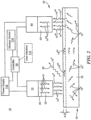
- Fig. 1 shows one embodiment of contactless system 10 for assessing of tissue viability and other hemodynamic parameters.
- System 10 preferably includes one or more light sources 12 configured to emit light 14 at a predetermined wavelength sensitive to hemoglobin concentration associated with spontaneous hemodynamic oscillations at tissue 16 in predetermined area 18 of a human subject 20 having a burn wound or similar type wound where the tissue viability of human subject 20 needs to be determined, as discussed in the Background section above.
- Tissue 16 in predetermined area 18 may be any tissue in any area on human subject 20 having a burn wound or similar type wound, e.g., such as diabetic ulcers or similar type wounds.
- predetermined area 18 is located on the face, neck, and upper chest of human subject 20.
- predetermined area 18 may be any area of the human subject 20 having a burn wound or similar type wound where tissue viability needs to be determined.
- One or more light sources 12 are preferably placed above and proximate tissue 16 in predetermined area 18 and emit or illuminate light 14 having one or more wavelengths sensitive to hemoglobin concentration spontaneous oscillations and capable of probing the human tissue without being completely absorbed, as discussed in further detail below.
- one or more light sources 12 preferably emit or illuminate light 14 having wavelengths in an electromagnetic (EM) spectrum, e.g., in the range of about 500 nm to about 1000 nm.
- EM electromagnetic
- one or more light sources 12 may include near infrared (NIR) sensors and/or one or more near infrared spectroscopy (NIRS) sensors.
- NIR near infrared
- NIRS near infrared spectroscopy
- System 10 also includes one or more polarizers each coupled to one or more light sources.
- Fig. 2 shows an example of polarizer 22 coupled to light source 12.
- Each of the one or more light sources 12 shown in Fig. 1 similarly has polarizer 22 coupled thereto.
- Each polarizer 22, Fig. 2 coupled to light source 12 is configured to polarize light 14 to polarized light 14 p in a polarized state such that polarized light 14 p in the polarized state diffuses into tissue 16 in predetermined area 18 and polarized light 14 p is maintained in the polarized state at predetermined depth d-24.
- depth d-24 is in the range of about 0.1 mm to about 0.5 mm.
- polarized light 14 p when polarized light 14 p is incident on tissue 16 in predetermined area 18, some of the photons polarized light 14 p will reflect off the surface of tissue 16 and some photons will penetrate into tissue 16 where the photons will either be scattered or absorbed as shown. If light polarized 14 p incident light is reflected off the surface of the tissue 16, e.g., indicated at 26, the polarization state is perfectly maintained. However, the polarization state of the penetrating photons of polarized light 14 p may be affected by scattering events in tissue 16 which may be divided into two categories: polarization maintaining or depolarized.
- the degree of polarization can be maintained to discriminate the depth of penetration of light into the tissue of tissue 16, e.g., polarized light 14 pd at depth d-24, e.g., is about 0.1 mm to about 0.5 mm. Such a depth is typically needed for real-time assessment of tissue viability of tissue 16 in predetermined area 18 by clinicians in an objective manner, as discussed below.
- Polarized light 14 p emitted from each polarizer 22 provides a relatively low-cost solution to enable real-time assessment of the tissue viability and other hemodynamic parameters of tissue 16 in predetermined area 18.
- polarized light 14 p transversely propagates through time and space, it contains both oscillating orthogonal electric and magnetic field vectors.
- the polarization of polarized light 14 p as disclosed herein refers to the direction and manipulation of the oscillating electric field vector. Polarization may be produced and manipulated by polarizer 22 coupled to one or more light sources 12.
- Polarizer 22 may be placed in any desired position along path of light 14 from detectors 12, Figs. 1 and 2 , to tissue 16 in predetermined area 18.
- Polarized light 14 provided by one or more light sources 12 and polarizer 22 coupled thereto may include linearly polarized light 14', Fig. 3 , circular polarized 14" or elliptical polarized light 14′′′, depending on the arrangement of the optical components used.
- Linearly polarized light 14' may be produced when a single electric field oscillation plane is isolated using polarizer 22 configured as linear polarizer, where one oscillation plane is dictated by the polarizing axis. The resulting electric field vector is considered to oscillate in one plane in which the orthogonal Ex-30 and Ey-32 components are maintained the same phase and amplitude as shown.
- Circularly polarized light 14" may be provided by polarizer 22 coupled to one or more light sources 12 when one of the two Ex-30 and Ey-32 components of the linearly polarized electric field vector becoming out of phase by exactly ⁇ 90 from the other as shown.
- Circularly polarized light 14" may be provided by polarizer 22 coupled to one or more light sources 12 when polarizer 22 is configured as a quarter-wave plate rotated 45 degrees relative to the polarizing axis of the linear polarizer.
- the shape of the propagation may be considered as a helix rotating either clockwise or counter-clockwise, which is denoted as right-handed or left-handed respectively.
- Elliptically polarized light 14′′′ is provided by polarizer 22 coupled to one or more light sources 12 when linearly polarized light passing through polarizer 22 is configured as a wave plate or birefringent material where the electric field vector components become out of phase by any amount other than ⁇ 90 degrees.
- Polarized light 14', polarized light 14" or polarized light 14′′′ provided by polarizer 36 coupled to one or more light sources 12 under these different polarization states will respond differently when focused on a turbid media, such as tissue 16, Fig. 1 , of human subject 20 in predetermined area 18.
- polarized light 14 p and polarized light 14 pd may be one or more of polarized light 14', 14", and/or 14′′′, Fig. 3 .
- System 10 may also include one or more light filtering lenses coupled to one or more light sources 12, e.g., light filtering lens 46 shown coupled to polarizer 22.
- Light filtering lens 46 is preferably configured to be transmissive within the desired operating spectrum discussed above and configured to block EM waves outside of the desired spectrum.
- System 10 also includes one or more detectors 40, Figs. 1 and 2 , which each include detector polarizer 42, Fig. 2 , coupled thereto.
- one or more detectors 40 preferably include one or more high-quality CCD cameras, one or more CMOS cameras, or similar type detectors.
- One or more detectors 40 may each include sensors having an analog amplifier and filter configured to increase the gain on the signal and reduces background noise to create clean images.
- Each of detector polarizer 42 are configured to discriminate between polarized light 14 pd maintained in the polarized state and at the predetermined depth, d-24, in from tissue 16 and polarized light 14 p reflected from tissue 16 which has not been maintained in the polarized state and at the predetermined depth.
- each detector polarizer 42 coupled to detector 40 discriminates between polarized light 14 pd that has been maintained in the polarized state at predetermined depth, d-24, in tissue 16 and polarized light 14 p which has not been maintained in the polarized state at predetermined depth, d-24.
- One or more detectors 40, Figs. 1 and 2 are configured to generate a plurality of frames of tissue 16, Figs. 1 and 2 , in predetermined area 18 from discriminated polarized light 14 pd reflected from tissue 16 in predetermined area 18 at predetermined depth, d-24, Fig. 2 , e.g., plurality of frames 40, Fig. 4 , at different points in time ranging from, t 1 , t 2 , t 3 ... t N .
- System 10 also includes controller 50, Figs. 1 and 2 , coupled to one or more light sources 12 and one or more detectors 40.
- Controller 50 may be a processor, one or more processors, an application-specific integrated circuit (ASIC), firmware, hardware, and/or software (including firmware, resident software, micro-code, and the like) or a combination of both hardware and software that may all generally be referred to herein as a "controller", which may be part of contactless system 10 and method thereof for assessing tissue viability and other hemodynamic parameters.
- ASIC application-specific integrated circuit
- Computer program code for the programs for carrying out the instructions or operation of controller 50 may be written in any combination of one or more programming languages, including an object oriented programming language, e.g., C++, Smalltalk, Java, and the like, or conventional procedural programming languages, such as the "C" programming language or similar programming languages.
- object oriented programming language e.g., C++, Smalltalk, Java, and the like
- conventional procedural programming languages such as the "C" programming language or similar programming languages.
- controller 50 uses equation (1) below to averages the number of pixels within each ROI-52: ⁇ N ⁇ 1 n ROI NPIXELS where n is the number of pixels in the selected ROI and N is the number of acquired frames.
- Controller 50 then detrends raw reference signal 56, indicated at 58, to create detrended raw reference signal 50.
- Controller 50 then performs frequency domain analysis of detrended raw reference signal 60 and identifies a frequency band of interest associated with the spontaneous hemodynamic oscillations.
- controller 50 has identified the frequency band of interest between F 1 -62 and F 2 -64 associated with spontaneous hemodynamic oscillations 66.
- the frequency band of interest associated with the spontaneous hemodynamic oscillations is typically in the range of 0.05 Hz to about 1.0 Hz, as discussed above.
- Controller 50 then performs inverse fast Fourier transform (iFFT), indicated at 68, within the frequency band of interest, F 1 -62 to F 2 -64, to generate reference signal (R s ) 70 indicative of blood volume oscillations at selected hemodynamic oscillations.
- iFFT inverse fast Fourier transform
- controller 50 For each sample of reference signal 70 at a predetermined point in time, controller 50 multiplies the sample by each pixel of a frame at the same predetermined point in time to generate three-dimensional correlation matrix 72 which includes a plurality of correlation matrix frames 74 at each predetermined point in time. As discussed above, each of the plurality of frames 40 is acquired at a various point of time, e.g., time ranging from t 1 , t 2 , t 3 , ... t N .
- Reference signal 70 shown in greater detail in Fig. 5 , includes the same number of samples as the number of plurality of frames 40, Fig. 4 , e.g., sample-80, Fig.
- Controller 50 multiplies each sample by each pixel of each of the plurality of frames 40 to generate correlation matrix 72 with a plurality of correlation matrix frames 74.
- correlation matrix 72 is generated using equation (2): FRAME i ⁇ R Si where FRAME 1 is each individual pixels in specific frame at time i , e.g., t 1 , t 2 , t 3 , ... t N ., and R Si is a sample at time i of the Reference Signal, e.g., t 1 , t 2 , t 3 , ... t N .
- Controller 50 then adds the plurality of correlation matrix frames 74 at each predetermined point in time to generate two-dimensional hemodynamic map 100, Fig. 4 , indicative of the strength of spontaneous hemodynamic oscillations to assess the viability of tissue 16 in predetermined area 18.
- N is the total amount of acquired frames, and CMx is the hemodynamic map showing areas of viable tissue.
- system 10, Fig. 1 preferably includes display device 102 coupled electronically or wirelessly to controller 50, e.g., a computer monitor, a smart phone, a tablet, or similarly type device, which displays two-dimensional hemodynamic map 100.
- controller 50 e.g., a computer monitor, a smart phone, a tablet, or similarly type device, which displays two-dimensional hemodynamic map 100.
- system 10 provides hemodynamic map 100, Figs. 1 and 2 , of tissue 16 in predetermined area 18 and at a depth of about 0.1 mm to about 0.5 mm needed for real-time assessment of the viability of tissue 16 in predetermined area 18 or other hemodynamic parameters, e.g., heart rate, resting heart rate, heart rate variability, tissue saturation for patients suffering from diminished blood circulation, and the like.
- system 10 provides hemodynamic map 100 which shows viable and necrotic tissue areas. If hemodynamic oscillations are detected and shown on hemodynamic map 100, e.g. indicated at 106 in caption 108, or shown in Fig. 4 , the tissue is viable. If hemodynamic oscillations are not shown, and therefore not detected by the procedure described above, on hemodynamic map 100, the tissue is necrotic, e.g., indicated at 108, Figs. 1 and 4 .
- Hemodynamic map 100 Figs. 2 and 4 preferably has a maximum field of view (FOV) of tissue 16 in predetermined area 18 where tissue viability needs to be determined.
- FOV maximum field of view
- the FOV e.g., FOV-104, Fig. 1
- displayed on display device 102 provides a real-time view of tissue 16 in predetermined area 18 needed for real-time assessment of tissue viability in an objective manner.
- FOV-104 of tissue 16 in predetermined area 18 may be about 10 inches by 10 inches. In other examples, FOV-104 of tissue 16 in predetermined area 18 may be larger or smaller than 10 inches by 10 inches as needed.
- Controller 50 is also preferably configured to store data associated with one or more hemodynamic maps 100 created by controller 100 in storage device 110.
- Storage device 110 may include any combination of computer-readable media or memory.
- the computer-readable media or memory may be a computer-readable signal medium or a computer-readable storage medium.
- a computer-readable storage medium or memory may be, an electronic, magnetic, optical, electromagnetic, infrared, or semiconductor system, apparatus, or device, or any suitable combination of the foregoing.
- ⁇ may include an electrical connection having one or more wires, a portable computer diskette, a hard disk, a random access memory (RAM), a read-only memory (ROM), an erasable programmable read-only memory (EPROM or Flash memory), an optical fiber, a portable compact disc read-only memory (CD-ROM), an optical storage device, a magnetic storage device, or any suitable combination of the foregoing.
- the computer-readable storage medium or memory may be any tangible medium that can contain, or store one or more programs for use by or in connection with one or more processors on a computing device such as a computer, a tablet, a cell phone, a smart device, or similar type device. Controller 50 may also be configured to compress the data associated with the hemodynamic maps.
- system 10 and the method thereof may implement spectral estimation techniques of the ambient illumination to remove uncontrolled ambient light changes.
- system 10 and the method thereof may remove ambient lighting artifacts at the acquisition level by removing temporal changes in ambient illumination measured during programmed periods of non-active tissue illumination.
- System 10 also preferably includes user interface 112 coupled to controller 50 electronically or wirelessly which may allow a user of system 10 to visualize and interact with the stored or real-time data. Data may be retrieved from controller 50 and storage device 110 via a data jack or by wireless communication, as known by those skilled in the art.
- System 10 also includes power supply 116 configured to provide power to one or more light sources 12, one or more detectors 20, controller 50, and/or display device 102. In one design, power supply 116 may include batteries for portable applications.
- contactless system 10 and method for assessing tissue viability and other hemodynamic parameters may be a standalone device for operation room, a portable device, or integrated into wearable tools worn by medical personnel.
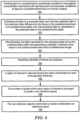
- One example of the method for assessing tissue viability and other hemodynamic parameters includes emitting light at a predetermined wavelength sensitive to hemoglobin concentration associated with spontaneous hemodynamic oscillations at tissue in a predetermined area of a human subject, step 150, Fig. 6 .
- the method also includes polarizing the light to a polarized state such that the polarized light in the polarized state diffuses into the tissue in the predetermined area at a predetermined depth such that the polarized light is maintained in the polarized state at the polarized depth, step 152.
- the method also includes discriminating the light maintained in the polarized state and at the predetermined depth and generating a plurality of frames of the tissue in the predetermined area at the predetermined depth, step 154.
- a plurality of frames are then acquired, step 156.
- a region of interest is then selected having the same coordinates for each of the plurality of frames, step 158.
- the number of pixels within each region of interest is averaged to create a raw reference signal, step 160.
- the raw reference signal is detrended to create a detrended raw reference signal, step 162.
- Frequency domain analysis is performed of the detrended raw reference signal, step 168.
- a frequency band of interest is identified associated with the spontaneous hemodynamic oscillations, step 170.
- An inverse fast Fourier transform (iFFT) is performed within the frequency band of interest to generate a raw reference signal indicative of blood volume oscillations at a selected spontaneous hemodynamic oscillation, step 172.
- iFFT inverse fast Fourier transform
- the sample For each sample of the raw reference signal at a predetermined point in time, the sample is multiplied by each pixel of a frame at the same predetermined point in time to generate a three-dimensional coordinate matrix including a plurality of correlation matrix frames at each predetermined point in time, step 174.
- the plurality of correlation matrix frames at each predetermined point in time are added to generate a two-dimensional hemodynamic map indicative of the strength of the spontaneous hemodynamic oscillations to assess the viability of tissue in the predetermined area or assess the viability of other hemodynamic parameters, step 176.
- system 10 and the method thereof provides a contactless real-time assessment of tissue viability and other hemodynamic parameters that allows a user to quantitatively assess the tissue health to provide objective metrics to support and guide accurate tissue excision of a burn wound or similar type wound.
- System 10 and the method thereof allows clinicians to selecting a level of debridement of a burn wound at a desired depth to minimize inflammation and determine the optimal treatment and remove virtually all the necrotic tissue in the burn wound or similar type wound in a time efficient manner.
- System 10 and the method thereof eliminates the need for intrusive tissue contact and preferably provides for long distance tissue viability assessment monitoring when compared to more conventional invasive imaging systems and methods discussed in the Background section.
- System 10 and the method thereof may provide opportunities in settings where multi-individual assessment may be extremely difficult or not feasible, such as intensive care units, emergency rooms, or where the condition of the patient may not allow for contact measurements.
- system 10 and the method thereof relying on spontaneous hemodynamic oscillation measurements discussed above with reference to one or more of Fig. 1-6 , rather than absolute concentration measurements of chromophores present in the cardiovascular system, is an optical path length factor approximation is not required by system 10 and the method thereof. This may eliminate the need to rely on estimation errors.
- System 10 and method thereof unlike conventional near infrared spectroscopy (NIRS) techniques, preferably does not require absolute concentration retrieval of the chromophores present in the cardiovascular system of tissue 16 of predetermined area 18 of human subject 16. Instead, system 10 and the method thereof preferably utilizes controller 50, one or more light sources 12, and one or more detectors 20. In one example.
- NIRS near infrared spectroscopy
Landscapes
- Health & Medical Sciences (AREA)
- Life Sciences & Earth Sciences (AREA)
- Physics & Mathematics (AREA)
- Engineering & Computer Science (AREA)
- Cardiology (AREA)
- Animal Behavior & Ethology (AREA)
- Public Health (AREA)
- Pathology (AREA)
- Veterinary Medicine (AREA)
- Biomedical Technology (AREA)
- Heart & Thoracic Surgery (AREA)
- Medical Informatics (AREA)
- Molecular Biology (AREA)
- Surgery (AREA)
- Biophysics (AREA)
- General Health & Medical Sciences (AREA)
- Physiology (AREA)
- Computer Vision & Pattern Recognition (AREA)
- Spectroscopy & Molecular Physics (AREA)
- Optics & Photonics (AREA)
- Mathematical Physics (AREA)
- Artificial Intelligence (AREA)
- Pulmonology (AREA)
- Psychiatry (AREA)
- Signal Processing (AREA)
- Hematology (AREA)
- Dermatology (AREA)
- Measurement Of The Respiration, Hearing Ability, Form, And Blood Characteristics Of Living Organisms (AREA)
- Investigating Or Analysing Materials By Optical Means (AREA)
Claims (14)
- Système sans contact destiné à évaluer la viabilité d'un tissu et d'autres paramètres hémodynamiques, le système comprenant :une ou plusieurs sources de lumière configurées pour émettre de la lumière à une longueur d'onde prédéterminée sensible à la concentration d'hémoglobine associée à des oscillations hémodynamiques spontanées au niveau d'un tissu dans une zone prédéterminée d'un sujet humain ;un ou plusieurs polariseurs chacun couplés à une ou plusieurs des une ou plusieurs sources de lumière configurés pour polariser la lumière vers un état polarisé de sorte que la lumière polarisée dans l'état polarisé se diffuse jusque dans le tissu dans la zone prédéterminée à une profondeur prédéterminée et la lumière polarisée est maintenue dans l'état polarisé à la profondeur prédéterminée ;un ou plusieurs détecteurs incluant chacun un polariseur de détecteur couplé à ceux-là, chaque polariseur de détecteur configuré pour distinguer la lumière polarisée réfléchie maintenue dans l'état polarisé et à la profondeur prédéterminée de la lumière polarisée réfléchie qui n'a pas été maintenue dans l'état polarisé et à la profondeur prédéterminée, chacun des un ou plusieurs détecteurs configuré pour générer une pluralité de cadres du tissu dans la zone prédéterminée à la profondeur prédéterminée ; etun dispositif de commande couplé aux une ou plusieurs sources de lumière et aux un ou plusieurs détecteurs, le dispositif de commande configuré pour :acquérir la pluralité de cadre ;sélectionner une région d'intérêt ayant les mêmes coordonnées pour chacun de la pluralité de cadres ;établir la moyenne du nombre de pixels au sein de chaque région d'intérêt pour créer un signal de référence brut ;éliminer la tendance dans le signal de référence brut pour créer un signal de référence brut dont la tendance a été éliminée ;réaliser une analyse de domaine fréquentiel du signal de référence brut dont la tendance a été éliminée,identifier une bande de fréquences d'intérêt associée aux oscillations hémodynamiques spontanées ;réaliser une transformée de Fourier rapide inverse au sein de la bande de fréquences d'intérêt pour générer un signal de référence représentatif d'oscillations de volume sanguin à une oscillation hémodynamique spontanée sélectionnée ;pour chaque échantillon du signal de référence à un point prédéterminé dans le temps, multiplier l'échantillon par chaque pixel d'un cadre au même point prédéterminé dans le temps pour générer une matrice de coordonnées tridimensionnelle incluant une pluralité de cadres de matrice de corrélation à chaque point prédéterminé dans le temps ; etajouter la pluralité de cadres de matrice de corrélation à chaque point prédéterminé dans le temps pour générer la carte hémodynamique bidimensionnelle représentative de la force de l'oscillation hémodynamique spontanée pour évaluer la viabilité du tissu dans la zone prédéterminée.
- Système selon la revendication 1 dans lequel les oscillations hémodynamiques spontanées ont une fréquence dans la plage de 0,05 Hz à environ 1,5 Hz.
- Système selon la revendication 1 dans lequel la longueur d'onde prédéterminée est dans la plage d'environ 500 nm à environ 1 000 nm.
- Système selon la revendication 1 dans lequel la profondeur prédéterminée est dans la plage d'environ 0,1 mm à environ 0,5 mm.
- Système selon la revendication 1 dans lequel les autres paramètres hémodynamiques incluent un ou plusieurs paramètres parmi : le rythme cardiaque, le rythme cardiaque au repos, la variabilité du rythme cardiaque, et la saturation tissulaire pour des patients souffrant d'une circulation sanguine diminuée.
- Système selon la revendication 1 dans lequel les un ou plusieurs détecteurs incluent une caméra CCD ou une caméra CMOS.
- Système selon la revendication 1 dans lequel la zone prédéterminée inclut une zone de brûlure d'un sujet humain ou une zone de plaie d'un sujet humain.
- Système selon la revendication 1 incluant en outre une lentille filtrant la lumière couplée à une ou plusieurs sources de lumière.
- Procédé sans contact destiné à évaluer la viabilité d'un tissu et d'autres paramètres hémodynamiques, le procédé comprenant :l'émission de lumière à une longueur d'onde prédéterminée sensible à la concentration d'hémoglobine associée à des oscillations hémodynamiques spontanées au niveau d'un tissu dans une zone prédéterminée d'un sujet humain ;la polarisation de la lumière vers un état polarisé de sorte que la lumière polarisée dans l'état polarisé se diffuse jusque dans le tissu dans la zone prédéterminée à une profondeur prédéterminée et la lumière polarisée est maintenue dans l'état polarisé à la profondeur polarisée ;la distinction de la lumière polarisée réfléchie maintenue dans l'état polarisé et à la profondeur prédéterminée de la lumière polarisée réfléchie qui n'a pas été maintenue dans l'état polarisé et à la profondeur prédéterminée et la génération d'une pluralité de cadres du tissu dans la zone prédéterminée à la profondeur prédéterminée ;l'acquisition de la pluralité de cadres ;la sélection d'une région d'intérêt ayant les mêmes coordonnées pour chacun de la pluralité de cadres ;l'établissement de la moyenne du nombre de pixels au sein de chaque région d'intérêt pour créer un signal de référence brut ;l'élimination de la tendance dans le signal de référence brut pour créer un signal de référence brut dont la tendance a été éliminée ;la réalisation d'une analyse de domaine fréquentiel du signal de référence brut dont la tendance a été éliminée ;l'identification d'une bande de fréquences d'intérêt associée aux oscillations hémodynamiques spontanées ;la réalisation d'une transformée de Fourier rapide inverse au sein de la bande de fréquences d'intérêt pour générer un signal de référence représentatif d'oscillations de volume sanguin à une oscillation hémodynamique spontanée sélectionnée ;pour chaque échantillon du signal de référence à un point déterminé dans le temps, la multiplication de l'échantillon par chaque pixel d'un cadre au même point prédéterminé dans le temps pour générer une matrice de coordonnées tridimensionnelle incluant une pluralité de cadres de matrice de corrélation à chaque point prédéterminé dans le temps ; etl'ajout de la pluralité de cadres de matrice de corrélation à chaque point prédéterminé dans le temps pour générer une carte hémodynamique bidimensionnelle représentative de la force de l'oscillation hémodynamique spontanée pour évaluer la viabilité du tissu dans la zone prédéterminée.
- Procédé selon la revendication 9 dans lequel l'ajout de la pluralité de cadres de matrice de corrélation à chaque point prédéterminé dans le temps pour générer une carte hémodynamique bidimensionnelle représentative de la force de l'oscillation hémodynamique spontanée évalue la viabilité d'autres paramètres hémodynamiques incluant un ou plusieurs paramètres parmi : le rythme cardiaque, le rythme cardiaque au repos, la variabilité du rythme cardiaque, et la saturation tissulaire pour des patients souffrant d'une circulation sanguine diminuée.
- Procédé selon la revendication 9 dans lequel les oscillations hémodynamiques spontanées ont une fréquence dans la plage de 0,05 Hz à environ 1,5 Hz.
- Procédé selon la revendication 9 dans lequel la longueur d'onde prédéterminée est dans la plage d'environ 500 nm à environ 1 000 nm.
- Procédé selon la revendication 9 dans lequel la profondeur prédéterminée est dans la plage d'environ 0,1 mm à environ 0,5 mm.
- Procédé selon la revendication 9 dans lequel la zone prédéterminée inclut une zone de brûlure d'un sujet humain ou une zone de plaie d'un sujet humain.
Applications Claiming Priority (2)
| Application Number | Priority Date | Filing Date | Title |
|---|---|---|---|
| US201862621873P | 2018-01-25 | 2018-01-25 | |
| PCT/US2019/012323 WO2019152133A1 (fr) | 2018-01-25 | 2019-01-04 | Système sans contact et procédé d'évaluation de la viabilité d'un tissu et d'autres paramètres hémodynamiques |
Publications (4)
| Publication Number | Publication Date |
|---|---|
| EP3742964A1 EP3742964A1 (fr) | 2020-12-02 |
| EP3742964A4 EP3742964A4 (fr) | 2021-10-27 |
| EP3742964C0 EP3742964C0 (fr) | 2024-11-27 |
| EP3742964B1 true EP3742964B1 (fr) | 2024-11-27 |
Family
ID=67299567
Family Applications (1)
| Application Number | Title | Priority Date | Filing Date |
|---|---|---|---|
| EP19747421.6A Active EP3742964B1 (fr) | 2018-01-25 | 2019-01-04 | Système sans contact et procédé d'évaluation de la viabilité d'un tissu et d'autres paramètres hémodynamiques |
Country Status (3)
| Country | Link |
|---|---|
| US (3) | US10448835B2 (fr) |
| EP (1) | EP3742964B1 (fr) |
| WO (1) | WO2019152133A1 (fr) |
Families Citing this family (3)
| Publication number | Priority date | Publication date | Assignee | Title |
|---|---|---|---|---|
| EP3742964B1 (fr) * | 2018-01-25 | 2024-11-27 | Vivonics, Inc. | Système sans contact et procédé d'évaluation de la viabilité d'un tissu et d'autres paramètres hémodynamiques |
| US11426076B2 (en) | 2019-11-27 | 2022-08-30 | Vivonics, Inc. | Contactless system and method for assessing and/or determining hemodynamic parameters and/or vital signs |
| CA3228473A1 (fr) * | 2021-08-11 | 2023-02-16 | Kimani Toussaint | Determination optique d'un parametre de variabilite cardiovasculaire independant de contributions cutanees |
Family Cites Families (9)
| Publication number | Priority date | Publication date | Assignee | Title |
|---|---|---|---|---|
| BR9611136A (pt) * | 1995-10-23 | 1999-09-14 | Cytometrics Inc | Processo e aparelho para análise de imagem refletida |
| CA2541297C (fr) * | 2003-10-03 | 2013-12-10 | Academisch Medisch Centrum | Systeme et methode de representation en images de la reflectance d'un substrat |
| WO2006058306A2 (fr) * | 2004-11-29 | 2006-06-01 | Hypermed, Inc. | Imagerie medicale en hyperespace spectral destinee a l'evaluation de tissus et de tumeurs |
| US20070100246A1 (en) | 2005-10-31 | 2007-05-03 | Hyde Christopher T | Heart rate based bioassessment method and apparatus |
| WO2009005748A1 (fr) * | 2007-06-29 | 2009-01-08 | The Trustees Of Columbia University In The City Ofnew York | Systèmes et procédés d'imagerie optique ou de spectroscopie |
| US20100210931A1 (en) | 2008-04-04 | 2010-08-19 | Modulate Imaging Inc. | Method for performing qualitative and quantitative analysis of wounds using spatially structured illumination |
| US8182425B2 (en) * | 2010-05-18 | 2012-05-22 | Johnson & Johnson Consumer Companies, Inc. | Method for measuring skin hydration |
| WO2016094439A1 (fr) * | 2014-12-08 | 2016-06-16 | Munoz Luis Daniel | Dispositif, système et procédés d'évaluation de structures, de pathologie, et de cicatrisation tissulaires |
| EP3742964B1 (fr) * | 2018-01-25 | 2024-11-27 | Vivonics, Inc. | Système sans contact et procédé d'évaluation de la viabilité d'un tissu et d'autres paramètres hémodynamiques |
-
2019
- 2019-01-04 EP EP19747421.6A patent/EP3742964B1/fr active Active
- 2019-01-04 WO PCT/US2019/012323 patent/WO2019152133A1/fr not_active Ceased
- 2019-01-04 US US16/239,734 patent/US10448835B2/en not_active Ceased
-
2020
- 2020-10-28 US US17/082,680 patent/USRE49639E1/en active Active
-
2023
- 2023-08-02 US US18/363,802 patent/US20230389800A1/en not_active Abandoned
Also Published As
| Publication number | Publication date |
|---|---|
| EP3742964A4 (fr) | 2021-10-27 |
| US20230389800A1 (en) | 2023-12-07 |
| WO2019152133A1 (fr) | 2019-08-08 |
| US10448835B2 (en) | 2019-10-22 |
| EP3742964A1 (fr) | 2020-12-02 |
| EP3742964C0 (fr) | 2024-11-27 |
| USRE49639E1 (en) | 2023-09-05 |
| US20190223730A1 (en) | 2019-07-25 |
Similar Documents
| Publication | Publication Date | Title |
|---|---|---|
| US20230389800A1 (en) | Contactless System and Method for Assessing Tissue Viability and Other Hemodynamic Parameters | |
| Boas et al. | Laser speckle contrast imaging in biomedical optics | |
| Murray et al. | Laser Doppler imaging: a developing technique for application in the rheumatic diseases | |
| EP0850018B1 (fr) | Appareil spectroscopique pour l'evaluation des lesions de la peau par brulure | |
| US6889075B2 (en) | Optical imaging of subsurface anatomical structures and biomolecules | |
| JP5340648B2 (ja) | 被検体情報算出装置及び被検体情報算出方法 | |
| CA2333565C (fr) | Processus de modulation tissulaire destine a l'analyse spectroscopique quantitative non invasive in vivo des tissus | |
| US20180158187A1 (en) | Methods and systems for characterizing tissue of a subject | |
| Šćepanović et al. | Multimodal spectroscopy detects features of vulnerable atherosclerotic plaque | |
| Mennes et al. | Novel optical techniques for imaging microcirculation in the diabetic foot | |
| US20130286379A1 (en) | Combined light source photoacoustic system | |
| EP3033005A2 (fr) | Systèmes et procédés d'évaluation de revascularisation | |
| US10265544B2 (en) | Real-time tumor perfusion imaging during radiation therapy delivery | |
| Zhao et al. | Noncontact speckle contrast diffuse correlation tomography of blood flow distributions in burn wounds: a preliminary study | |
| US10149620B2 (en) | Methods and systems using LED sources to create contrast agents for mid-infrared imaging of blood vessels | |
| US20240324881A1 (en) | Optical sensor for monitoring temperature-induced changes in biological tissues | |
| Jakovels et al. | Noncontact monitoring of vascular lesion phototherapy efficiency by RGB multispectral imaging | |
| JP6378311B2 (ja) | 物体を特徴付ける方法とシステム | |
| Hren et al. | Laser speckle contrast imaging of perfusion in oncological clinical applications: a literature review. | |
| Li et al. | A reflectance model for non-contact mapping of venous oxygen saturation using a CCD camera | |
| Kacprzak et al. | Application of a time-resolved optical brain imager for monitoring cerebral oxygenation during carotid surgery | |
| Park et al. | Multi-wavelength imaging photoplethysmography for non-invasive and non-contact assessment of burn severity | |
| Schlosser et al. | Application of a new laser Doppler imaging system in planning and monitoring of surgical flaps | |
| Sowa | SnapshotNIR: a handheld multispectral imaging system for tissue viability assessment | |
| Li et al. | An upgraded camera-based imaging system for mapping venous blood oxygenation in human skin tissue |
Legal Events
| Date | Code | Title | Description |
|---|---|---|---|
| STAA | Information on the status of an ep patent application or granted ep patent |
Free format text: STATUS: THE INTERNATIONAL PUBLICATION HAS BEEN MADE |
|
| PUAI | Public reference made under article 153(3) epc to a published international application that has entered the european phase |
Free format text: ORIGINAL CODE: 0009012 |
|
| STAA | Information on the status of an ep patent application or granted ep patent |
Free format text: STATUS: REQUEST FOR EXAMINATION WAS MADE |
|
| 17P | Request for examination filed |
Effective date: 20200817 |
|
| AK | Designated contracting states |
Kind code of ref document: A1 Designated state(s): AL AT BE BG CH CY CZ DE DK EE ES FI FR GB GR HR HU IE IS IT LI LT LU LV MC MK MT NL NO PL PT RO RS SE SI SK SM TR |
|
| AX | Request for extension of the european patent |
Extension state: BA ME |
|
| DAV | Request for validation of the european patent (deleted) | ||
| DAX | Request for extension of the european patent (deleted) | ||
| A4 | Supplementary search report drawn up and despatched |
Effective date: 20210923 |
|
| RIC1 | Information provided on ipc code assigned before grant |
Ipc: A61B 5/026 20060101ALI20210917BHEP Ipc: A61B 5/349 20210101ALI20210917BHEP Ipc: A61B 5/1455 20060101ALI20210917BHEP Ipc: A61B 5/0205 20060101ALI20210917BHEP Ipc: A61B 5/02 20060101AFI20210917BHEP |
|
| 19U | Interruption of proceedings before grant |
Effective date: 20221030 |
|
| 19W | Proceedings resumed before grant after interruption of proceedings |
Effective date: 20230301 |
|
| STAA | Information on the status of an ep patent application or granted ep patent |
Free format text: STATUS: EXAMINATION IS IN PROGRESS |
|
| 17Q | First examination report despatched |
Effective date: 20240117 |
|
| GRAP | Despatch of communication of intention to grant a patent |
Free format text: ORIGINAL CODE: EPIDOSNIGR1 |
|
| STAA | Information on the status of an ep patent application or granted ep patent |
Free format text: STATUS: GRANT OF PATENT IS INTENDED |
|
| INTG | Intention to grant announced |
Effective date: 20240716 |
|
| GRAJ | Information related to disapproval of communication of intention to grant by the applicant or resumption of examination proceedings by the epo deleted |
Free format text: ORIGINAL CODE: EPIDOSDIGR1 |
|
| STAA | Information on the status of an ep patent application or granted ep patent |
Free format text: STATUS: EXAMINATION IS IN PROGRESS |
|
| GRAP | Despatch of communication of intention to grant a patent |
Free format text: ORIGINAL CODE: EPIDOSNIGR1 |
|
| STAA | Information on the status of an ep patent application or granted ep patent |
Free format text: STATUS: GRANT OF PATENT IS INTENDED |
|
| GRAS | Grant fee paid |
Free format text: ORIGINAL CODE: EPIDOSNIGR3 |
|
| GRAA | (expected) grant |
Free format text: ORIGINAL CODE: 0009210 |
|
| STAA | Information on the status of an ep patent application or granted ep patent |
Free format text: STATUS: THE PATENT HAS BEEN GRANTED |
|
| INTC | Intention to grant announced (deleted) | ||
| AK | Designated contracting states |
Kind code of ref document: B1 Designated state(s): AL AT BE BG CH CY CZ DE DK EE ES FI FR GB GR HR HU IE IS IT LI LT LU LV MC MK MT NL NO PL PT RO RS SE SI SK SM TR |
|
| INTG | Intention to grant announced |
Effective date: 20241023 |
|
| REG | Reference to a national code |
Ref country code: GB Ref legal event code: FG4D |
|
| REG | Reference to a national code |
Ref country code: CH Ref legal event code: EP |
|
| REG | Reference to a national code |
Ref country code: IE Ref legal event code: FG4D |
|
| REG | Reference to a national code |
Ref country code: DE Ref legal event code: R096 Ref document number: 602019062589 Country of ref document: DE |
|
| U01 | Request for unitary effect filed |
Effective date: 20241127 |
|
| U07 | Unitary effect registered |
Designated state(s): AT BE BG DE DK EE FI FR IT LT LU LV MT NL PT RO SE SI Effective date: 20241203 |
|
| U20 | Renewal fee for the european patent with unitary effect paid |
Year of fee payment: 7 Effective date: 20241223 |
|
| PG25 | Lapsed in a contracting state [announced via postgrant information from national office to epo] |
Ref country code: IS Free format text: LAPSE BECAUSE OF FAILURE TO SUBMIT A TRANSLATION OF THE DESCRIPTION OR TO PAY THE FEE WITHIN THE PRESCRIBED TIME-LIMIT Effective date: 20250327 Ref country code: HR Free format text: LAPSE BECAUSE OF FAILURE TO SUBMIT A TRANSLATION OF THE DESCRIPTION OR TO PAY THE FEE WITHIN THE PRESCRIBED TIME-LIMIT Effective date: 20241127 |
|
| PG25 | Lapsed in a contracting state [announced via postgrant information from national office to epo] |
Ref country code: ES Free format text: LAPSE BECAUSE OF FAILURE TO SUBMIT A TRANSLATION OF THE DESCRIPTION OR TO PAY THE FEE WITHIN THE PRESCRIBED TIME-LIMIT Effective date: 20241127 |
|
| PG25 | Lapsed in a contracting state [announced via postgrant information from national office to epo] |
Ref country code: NO Free format text: LAPSE BECAUSE OF FAILURE TO SUBMIT A TRANSLATION OF THE DESCRIPTION OR TO PAY THE FEE WITHIN THE PRESCRIBED TIME-LIMIT Effective date: 20250227 |
|
| PG25 | Lapsed in a contracting state [announced via postgrant information from national office to epo] |
Ref country code: GR Free format text: LAPSE BECAUSE OF FAILURE TO SUBMIT A TRANSLATION OF THE DESCRIPTION OR TO PAY THE FEE WITHIN THE PRESCRIBED TIME-LIMIT Effective date: 20250228 |
|
| PG25 | Lapsed in a contracting state [announced via postgrant information from national office to epo] |
Ref country code: PL Free format text: LAPSE BECAUSE OF FAILURE TO SUBMIT A TRANSLATION OF THE DESCRIPTION OR TO PAY THE FEE WITHIN THE PRESCRIBED TIME-LIMIT Effective date: 20241127 |
|
| PG25 | Lapsed in a contracting state [announced via postgrant information from national office to epo] |
Ref country code: RS Free format text: LAPSE BECAUSE OF FAILURE TO SUBMIT A TRANSLATION OF THE DESCRIPTION OR TO PAY THE FEE WITHIN THE PRESCRIBED TIME-LIMIT Effective date: 20250227 |
|
| PG25 | Lapsed in a contracting state [announced via postgrant information from national office to epo] |
Ref country code: SM Free format text: LAPSE BECAUSE OF FAILURE TO SUBMIT A TRANSLATION OF THE DESCRIPTION OR TO PAY THE FEE WITHIN THE PRESCRIBED TIME-LIMIT Effective date: 20241127 |
|
| PG25 | Lapsed in a contracting state [announced via postgrant information from national office to epo] |
Ref country code: SK Free format text: LAPSE BECAUSE OF FAILURE TO SUBMIT A TRANSLATION OF THE DESCRIPTION OR TO PAY THE FEE WITHIN THE PRESCRIBED TIME-LIMIT Effective date: 20241127 |
|
| PG25 | Lapsed in a contracting state [announced via postgrant information from national office to epo] |
Ref country code: CZ Free format text: LAPSE BECAUSE OF FAILURE TO SUBMIT A TRANSLATION OF THE DESCRIPTION OR TO PAY THE FEE WITHIN THE PRESCRIBED TIME-LIMIT Effective date: 20241127 |
|
| REG | Reference to a national code |
Ref country code: CH Ref legal event code: PL |
|
| PG25 | Lapsed in a contracting state [announced via postgrant information from national office to epo] |
Ref country code: MC Free format text: LAPSE BECAUSE OF FAILURE TO SUBMIT A TRANSLATION OF THE DESCRIPTION OR TO PAY THE FEE WITHIN THE PRESCRIBED TIME-LIMIT Effective date: 20241127 |
|
| PLBE | No opposition filed within time limit |
Free format text: ORIGINAL CODE: 0009261 |
|
| STAA | Information on the status of an ep patent application or granted ep patent |
Free format text: STATUS: NO OPPOSITION FILED WITHIN TIME LIMIT |
|
| PG25 | Lapsed in a contracting state [announced via postgrant information from national office to epo] |
Ref country code: CH Free format text: LAPSE BECAUSE OF NON-PAYMENT OF DUE FEES Effective date: 20250131 |
|
| 26N | No opposition filed |
Effective date: 20250828 |
|
| PGFP | Annual fee paid to national office [announced via postgrant information from national office to epo] |
Ref country code: GB Payment date: 20251209 Year of fee payment: 8 |
|
| U20 | Renewal fee for the european patent with unitary effect paid |
Year of fee payment: 8 Effective date: 20251209 |
|
| PG25 | Lapsed in a contracting state [announced via postgrant information from national office to epo] |
Ref country code: IE Free format text: LAPSE BECAUSE OF NON-PAYMENT OF DUE FEES Effective date: 20250104 |