EP3744164B1 - Dispositif de coupe pour un mécanisme de coupe agricole ou forestier - Google Patents
Dispositif de coupe pour un mécanisme de coupe agricole ou forestier Download PDFInfo
- Publication number
- EP3744164B1 EP3744164B1 EP19177104.7A EP19177104A EP3744164B1 EP 3744164 B1 EP3744164 B1 EP 3744164B1 EP 19177104 A EP19177104 A EP 19177104A EP 3744164 B1 EP3744164 B1 EP 3744164B1
- Authority
- EP
- European Patent Office
- Prior art keywords
- cutting
- knife
- assembly according
- cutting assembly
- edge
- Prior art date
- Legal status (The legal status is an assumption and is not a legal conclusion. Google has not performed a legal analysis and makes no representation as to the accuracy of the status listed.)
- Active
Links
Images
Classifications
-
- A—HUMAN NECESSITIES
- A01—AGRICULTURE; FORESTRY; ANIMAL HUSBANDRY; HUNTING; TRAPPING; FISHING
- A01D—HARVESTING; MOWING
- A01D34/00—Mowers; Mowing apparatus of harvesters
- A01D34/01—Mowers; Mowing apparatus of harvesters characterised by features relating to the type of cutting apparatus
- A01D34/02—Mowers; Mowing apparatus of harvesters characterised by features relating to the type of cutting apparatus having reciprocating cutters
- A01D34/13—Cutting apparatus
- A01D34/14—Knife-bars
-
- A—HUMAN NECESSITIES
- A01—AGRICULTURE; FORESTRY; ANIMAL HUSBANDRY; HUNTING; TRAPPING; FISHING
- A01D—HARVESTING; MOWING
- A01D34/00—Mowers; Mowing apparatus of harvesters
- A01D34/01—Mowers; Mowing apparatus of harvesters characterised by features relating to the type of cutting apparatus
- A01D34/02—Mowers; Mowing apparatus of harvesters characterised by features relating to the type of cutting apparatus having reciprocating cutters
- A01D34/13—Cutting apparatus
- A01D34/18—Guard fingers; Ledger-plates
Definitions
- the invention relates to a cutting arrangement for an agricultural or forestry cutter, comprising: a lower part and an upper part which together form at least one finger which extends along a longitudinal axis, a blade gap being formed between the lower part and the upper part, a knife which is guided back and forth in the blade gap in a drive direction transversely to the longitudinal axis and which has at least one cutting edge.
- Cutting assemblies are known, for example, in mowers, which usually have a finger bar on which several fingers are arranged. A knife is guided in an oscillating manner relative to the finger bar, the knife comprising a knife rail to which a plurality of knife blades are attached. The knife blades form cutting edges that work together with shearbars formed by the mowing fingers.
- a corresponding mowing finger arrangement is in the publication EP 2 366 274 A2 described.
- the US 196107A describes a cutting or mowing mechanism with a mowing finger, in which a blade gap is formed, with a knife being guided back and forth in the blade gap, which has a cutting edge which has a lower cutting bevel and an upper cutting bevel.
- the DE 32 29 743 A1 shows a finger bar mower for harvesting machines with a reciprocating mowing knife made of knife blades arranged on a knife bar, which interact with the mowing fingers as counter-blades.
- a lower part and an upper part together form a mowing finger, with a blade gap being formed between the lower part and the upper part.
- the knife blades have a cutting edge which has a cutting bevel facing the upper part.
- the lower part is in two parts executed, wherein a guide part and a carrier together form the lower part and the guide part is arranged in sections between carrier and upper part.
- the U.S. 1,945,301 A refers to a blade guard of mowers and harvesters.
- the guard finger has an upper, rearwardly extending shield which serves to protect the knife blade and to provide an upper edge on each side against which the grass can rest under the action of the knives.
- the blade is provided with serrations on its side edges forming teeth which engage the grass or the like to ensure the grass or the like is held in the correct position for shearing.
- the U.S. 2002/005035 A1 relates to a mowing finger for an agricultural mowing machine of the kind commonly used in grass, grain and vegetable cutting machines, having two equal and parallel juxtaposed fingers formed by two superimposed hardened steel plates which are spaced in their rear and central portions exhibit. The front areas are connected, forming sharp points that curve upwards. A cutting gap is formed in the central portions to allow for the oscillating movement of the cutting blades, the blades of which act with serrated side edges to produce the shear cuts.
- a disadvantage of the cutting arrangements provided for mowing or for cutting crops is that they are limited to cutting stalks.
- An object of the invention is to provide a cutting arrangement which allows cutting of plant parts with greater strength and/or hardness.
- the cutting arrangement according to the invention for an agricultural or forestry cutter comprises a lower part and an upper part which together form at least one finger which extends along a longitudinal axis, with a blade gap being formed between the lower part and the upper part, and a knife which is Blade gap is guided back and forth in a drive direction transverse to the longitudinal axis and which has at least one cutting edge.
- the cutting edge has a lower cutting bevel facing the lower part and an upper cutting bevel facing the upper part.
- the cutting edge does not work together with a counter blade at the blade gap.
- the cutting edge therefore does not perform a scissor cut in conjunction with the finger.
- the finger advantageously serves as a counter-holder and the knife cuts through the material to be cut in the manner of a wedge cut or ax cut by means of the cutting edge with the lower cutting bevel and the upper cutting bevel. This allows clippings of greater thickness and strength to be cut through, such as branches.
- the lower cutting bevel and the upper cutting bevel preferably meet at a cutting edge and preferably enclose an acute cutting edge angle.
- the designations lower part and upper part do not refer to a specific orientation of the cutterbar in relation to a ground or a working machine, but only define top and bottom with regard to the cutterbar itself.
- the longitudinal axis of the finger extends in a Cartesian coordinate system with three spatial directions X, Y and Z in the X-direction, while the driving direction of the knife is in particular in the Z-direction.
- the bottom and the top are spaced apart in the Y-direction.
- the designations of components as upper and lower components are spaced apart in the Y-direction, with the upper components being located closer to the top than the bottom and with the bottom components being located closer to the bottom than the top.
- the part of the material to be cut is on the side of the upper part when cutting.
- the knife has a lower contact surface facing the lower part, to which the lower cutting bevel is arranged running at an angle, and that the knife has an upper contact surface facing the upper part, to which the upper cutting bevel is arranged running at an angle.
- the lower contact surface and the upper contact surface are preferably arranged parallel to one another.
- the cutting edge is preferably arranged in a thickness direction of the blade between the lower contact surface and the upper contact surface.
- the lower part is designed in two parts, with a guide part and a carrier together forming the lower part and with the guide part being arranged at least in sections between the carrier and the upper part.
- the guide part has a lower guide surface that delimits the knife gap and the upper part has an upper guide surface that also delimits the knife gap, the lower guide surface and the upper guide surface being arranged parallel to one another.
- the guide part has at least one lower counter-edge and the upper part has at least one upper counter-edge, which the cutting edge is guided past during the reciprocating movement of the knife, the upper counter-edge being toothed and the lower counter-edge being straight.
- the guide part preferably has lower mating edges on both sides of the longitudinal axis and the upper part has upper mating edges on both sides of the longitudinal axis.
- the lower part and the upper part form two or more fingers, the fingers being arranged parallel to one another and via at least one web on the lower part and/or on the upper part are connected to each other.
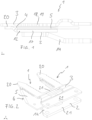
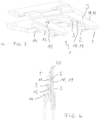
- the cutting assembly according to the invention for an agricultural or forestry cutter comprises a lower part 2 and an upper part 3, which together form at least one finger 1, the extends along a longitudinal axis.
- the lower part 2 and the upper part 3 form two fingers 1, the fingers 1 being arranged parallel to one another and connected to one another via at least one web 21 on the lower part 2 and/or on the upper part 3.
- This embodiment is also called double finger.
- two webs 21 are provided on the upper part 3 and one web 21 on the lower part 2, as in FIG figure 2 is recognizable.
- the lower part 2 and the upper part 3 are connected to one another at the tips 20 of the fingers 1 .
- the arrangement of the finger 1 by means of fastening means on a finger bar (not shown) is known to a person skilled in the art.
- the longitudinal axes of the two fingers 1 (not shown) extend parallel to one another in the X direction in a Cartesian coordinate system with three spatial directions X, Y and Z.
- a blade gap 4 is formed between the lower part 2 and the upper part 3 .
- a knife 5 is guided back and forth in a drive direction transverse to the longitudinal axis.
- the driving direction of the knife corresponds in particular to the Z-direction.
- the bottom part 2 and the top part 3 are spaced apart in the Y-direction.
- the Y-direction corresponds to a thickness direction Y of the blade 5.
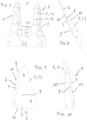
- the blade 5 has at least one cutting edge 6, which is described below with reference to FIG Figures 8 to 10 is described in more detail.
- the cutting edge 6 has a lower cutting bevel 7 facing the lower part 2 and an upper cutting bevel 8 facing the upper part 3 .
- the cutting edge 11 does not work together with a shearbar on the blade gap 4.
- the cutting edge 11 therefore does not perform a scissor cut in conjunction with the finger 1.
- the finger 1 serves as a counter-holder and the knife cuts through the material to be cut in the manner of a wedge cut or ax cut using the cutting edge 11. This allows cutting material of greater strength and strength to be severed, for example branches.
- the knife 5 preferably consists of a plurality of knife blades 22, each of which has at least one cutting edge 6, only one knife blade 22 being shown here.
- the skilled person is the arrangement of several knife blades 22 means Fastening means known on a cutter bar, not shown, to form the knife 5.
- the knife blade 22 preferably has two cutting edges 6 facing away from one another.
- the lower cutting bevel 7 and the upper cutting bevel 8 preferably abut one another at a cutting edge 11 and preferably enclose an acute cutting edge angle.
- the knife 5 has a lower contact surface 9 which faces the lower part 2 and to which the lower cutting bevel 7 is arranged running at an angle.
- An upper contact surface 10 of the blade 5 facing the upper part 3 is arranged at an angle to the upper cutting bevel 8 .
- the lower contact surface 9 and the upper contact surface 10 are preferably arranged parallel to one another.
- the cutting edge 6 is arranged between the lower contact surface 9 and the upper contact surface 10 in the thickness direction Y of the blade 5 .
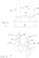
- the lower bearing surface 9 and the upper bearing surface 10 interact with the blade gap 4, which is described below with reference to FIG Figures 5 to 7 is explained in more detail.
- the lower part 2 is designed in two parts, with a guide part 12 and a carrier 14 forming the lower part 2 together.
- the guide part 12 is arranged in sections between the carrier 14 and the upper part 3 .
- the carrier 14 and the guide part 12 are in particular firmly connected to one another.
- the guide part 12 has a lower guide surface 15 which delimits the blade gap 4 together with an upper guide surface 16 on the upper part 3 .
- the lower guide surface 15 and the upper guide surface 16 are arranged parallel to one another.
- the guide part 12 has at least one lower counter-edge 17 and the upper part 3 has at least one upper counter-edge 18, past which the cutting edge 6 is guided during the reciprocating movement of the knife 5.
- the guide part 12 has four lower counter-edges 17, namely two per finger 1.
- the upper part 3 accordingly has four upper counter-edges 18.
- the upper counter-edges 18 have teeth 19, while the lower counter-edges 17 are straight.
- the toothing 19 advantageously holds the material to be cut during cutting.
- the material to be cut is fanned out by the teeth 19 only in the sections where no special requirements are placed on the cut.
- the part of the clippings remaining on the plant is advantageously given a clean cut by the straight counter-edges 17, as a result of which regrowth and/or penetration of fungi is prevented.
Landscapes
- Life Sciences & Earth Sciences (AREA)
- Environmental Sciences (AREA)
- Harvester Elements (AREA)
- Knives (AREA)
Claims (13)
- Dispositif de coupe pour un mécanisme de coupe agricole ou forestier comprenant :une partie inférieure (2) et une partie supérieure (3), qui forment en commun au moins un doigt, qui s'étend le long d'un axe longitudinal, sachant qu'un interstice pour lame est constitué entre la partie inférieure et la partie supérieure etun couteau (5),qui est guidé dans une direction d'entraînement en mouvement de va-et-vient dans l'interstice pour lame transversalement à l'axe longitudinal et qui comporte au moins un tranchant, sachant que le tranchant comporte un chanfrein de coupe inférieur tourné vers la partie inférieure et un chanfrein de coupe supérieur tourné vers la partie supérieure,sachant que la partie inférieure est exécutée en deux parties, sachant qu'une partie de guidage et un support (14) forment en commun la partie inférieure et sachant que la partie de guidage est disposée au moins par segments entre le support et la partie supérieure,sachant que la partie de guidage (12) comporte au moins une contre-arête inférieure et la partie supérieure comporte au moins une contre-arête supérieure sur lesquelles le tranchant est passé lors du mouvement de va-et-vient du couteau,et sachant que la contre-arête supérieure est dentée et la contre-arête inférieure est rectiligne.
- Dispositif de coupe selon la revendication 1,
caractérisé en ce que
le couteau (5) comporte une surface d'appui inférieure tournée vers la partie inférieure en direction de laquelle est disposé le chanfrein de coupe inférieur en formant un angle et en ce que le couteau comporte une surface d'appui supérieure tournée vers la partie supérieure en direction de la quelle est disposé le chanfrein de coupe supérieur en formant un angle. - Dispositif de coupe selon la revendication 2,
caractérisé en ce que
la surface d'appui inférieure et la surface d'appui supérieure sont disposées parallèlement l'une par rapport à l'autre. - Dispositif de coupe selon l'une quelconque des revendications 1 à 3,
caractérisé en ce que
le chanfrein de coupe inférieur et le chanfrein de coupe supérieur viennent en butée l'un contre l'autre sur une arête tranchante (11) et forment un angle de coupe aigu. - Dispositif de coupe selon la revendication 4,
caractérisé en ce que
l'arête tranchante (11) est disposée dans une direction d'épaisseur du couteau entre la surface d'appui inférieure et la surface d'appui supérieure. - Dispositif de coupe selon la revendication 1
caractérisé en ce que
la partie de guidage comporte une surface de guidage inférieure qui délimite l'interstice pour lame et en ce que la partie supérieure (3) comporte une surface de guidage supérieure, qui délimite l'interstice pour lame, sachant que la surface de guidage inférieure et la surface de guidage supérieure sont disposées parallèlement l'une par rapport à l'autre. - Dispositif de coupe selon l'une quelconque des revendications 1 à 6,
caractérisé en ce que
la partie de guidage (12) comporte des contre-arêtes inférieures des deux côtés de l'axe longitudinal et la partie supérieure comporte des contre-arêtes supérieures des deux côtés de l'axe longitudinal. - Dispositif de coupe selon l'une quelconque des revendications 1 à 7,
caractérisé en ce que
la partie inférieure (2) et la partie supérieure (3) sont reliées entre elles à une extrémité pointue. - Dispositif de coupe selon l'une quelconque des revendications 1 à 8,
caractérisé en ce que
la partie inférieure (2) et la partie supérieure (3) forment deux doigts ou plus, sachant que les doigts sont disposés parallèlement les uns par rapport aux autres et sont reliés entre eux sur la partie inférieure et/ou la partie supérieure par le biais d'au moins une barrette de montage. - Dispositif de coupe selon l'une quelconque des revendications 1 à 9,
caractérisé en ce que
le couteau (5) comporte des lames de couteau, qui comportent au moins un tranchant. - Dispositif de coupe selon la revendication 10,
caractérisé en ce que
les lames de couteau (22) comportent deux tranchants opposés l'un à l'autre. - Utilisation d'un dispositif de coupe selon la revendication 1 pour la coupe de branches.
- Utilisation selon la revendication 12,
caractérisée en ce que
la partie inférieure (2) est tournée vers la partie des branches restant sur la plante après la coupe.
Priority Applications (11)
| Application Number | Priority Date | Filing Date | Title |
|---|---|---|---|
| ES19177104T ES2949624T3 (es) | 2019-05-28 | 2019-05-28 | Disposición de corte para un mecanismo de corte agrícola o forestal |
| EP19177104.7A EP3744164B1 (fr) | 2019-05-28 | 2019-05-28 | Dispositif de coupe pour un mécanisme de coupe agricole ou forestier |
| PL19177104.7T PL3744164T3 (pl) | 2019-05-28 | 2019-05-28 | Układ tnący do rolniczego lub leśnego zespołu tnącego |
| JP2021570802A JP2022534599A (ja) | 2019-05-28 | 2020-05-27 | 農林業用の切断機構のための切断アセンブリ |
| AU2020281826A AU2020281826B2 (en) | 2019-05-28 | 2020-05-27 | Cutting assembly for an agricultural or forestry cutter |
| CN202080039973.XA CN113950242B (zh) | 2019-05-28 | 2020-05-27 | 用于农业或林业切割器的切割组件 |
| PCT/EP2020/064776 WO2020239879A1 (fr) | 2019-05-28 | 2020-05-27 | Système de coupe pour un appareil de coupe agricole ou forestier |
| CA3142111A CA3142111C (fr) | 2019-05-28 | 2020-05-27 | Systeme de coupe pour un appareil de coupe agricole ou forestier |
| US17/595,865 US12279551B2 (en) | 2019-05-28 | 2020-05-27 | Cutting assembly for an agricultural or forestry cutter |
| BR112021023745A BR112021023745A2 (pt) | 2019-05-28 | 2020-05-27 | Disposição de corte para uma unidade de corte agrícola ou florestal |
| UAA202106606A UA126998C2 (uk) | 2019-05-28 | 2020-05-27 | Ріжучий блок для ріжучого апарата, який застосовують у сільському або лісовому господарстві |
Applications Claiming Priority (1)
| Application Number | Priority Date | Filing Date | Title |
|---|---|---|---|
| EP19177104.7A EP3744164B1 (fr) | 2019-05-28 | 2019-05-28 | Dispositif de coupe pour un mécanisme de coupe agricole ou forestier |
Publications (3)
| Publication Number | Publication Date |
|---|---|
| EP3744164A1 EP3744164A1 (fr) | 2020-12-02 |
| EP3744164C0 EP3744164C0 (fr) | 2023-06-07 |
| EP3744164B1 true EP3744164B1 (fr) | 2023-06-07 |
Family
ID=66676273
Family Applications (1)
| Application Number | Title | Priority Date | Filing Date |
|---|---|---|---|
| EP19177104.7A Active EP3744164B1 (fr) | 2019-05-28 | 2019-05-28 | Dispositif de coupe pour un mécanisme de coupe agricole ou forestier |
Country Status (11)
| Country | Link |
|---|---|
| US (1) | US12279551B2 (fr) |
| EP (1) | EP3744164B1 (fr) |
| JP (1) | JP2022534599A (fr) |
| CN (1) | CN113950242B (fr) |
| AU (1) | AU2020281826B2 (fr) |
| BR (1) | BR112021023745A2 (fr) |
| CA (1) | CA3142111C (fr) |
| ES (1) | ES2949624T3 (fr) |
| PL (1) | PL3744164T3 (fr) |
| UA (1) | UA126998C2 (fr) |
| WO (1) | WO2020239879A1 (fr) |
Families Citing this family (4)
| Publication number | Priority date | Publication date | Assignee | Title |
|---|---|---|---|---|
| EP4094560A1 (fr) * | 2021-05-27 | 2022-11-30 | SMF - Holding GmbH | Couteau, en particulier pour une barre de coupe d'une machine agricole |
| DE102024126062A1 (de) | 2024-09-11 | 2026-03-12 | Betek Gmbh & Co. Kg | Schneidwerkzeug |
| DE202024002701U1 (de) | 2024-09-11 | 2026-01-30 | Betek Gmbh & Co. Kg | Schneidwerkzeug |
| DE102024126063A1 (de) | 2024-09-11 | 2026-03-12 | Betek Gmbh & Co. Kg | Schneidwerkzeug |
Family Cites Families (21)
| Publication number | Priority date | Publication date | Assignee | Title |
|---|---|---|---|---|
| US195907A (en) * | 1877-10-09 | thomson | ||
| GB191114070A (en) * | 1910-11-22 | 1911-12-14 | Albert J Seger | Improvements in and relating to Cutting Mechanisms for Mowing Machines and the like |
| US1959070A (en) * | 1932-03-07 | 1934-05-15 | Deere & Co | Cotton harvester |
| US1945301A (en) * | 1933-07-21 | 1934-01-30 | Wilson Ira Herbert | Guard for mowing and analogous machines |
| DE1690130U (de) * | 1954-07-06 | 1954-12-30 | Hermann Lederle | Vierschneidige maehmesserklinge. |
| AU1555066A (en) | 1966-12-20 | 1969-06-12 | Keech Castings Pty. Ltd | Finger and cutter base for mowers and headers |
| US3566592A (en) * | 1969-08-13 | 1971-03-02 | Emil A Jerman | Mower guard |
| JPS4864352U (fr) * | 1971-11-25 | 1973-08-15 | ||
| DE2855234C2 (de) * | 1978-12-21 | 1986-02-20 | Gustav Schumacher Ii | Doppelmähfinger für Fingerbalkenmähwerke |
| JPS5618026U (fr) | 1979-07-19 | 1981-02-17 | ||
| DE2945960A1 (de) * | 1979-11-14 | 1981-05-27 | Gustav Schumacher Ii | Maehfinger fuer fingerbalkenmaehwerke |
| DE3229743A1 (de) * | 1982-08-10 | 1984-02-16 | K G S - Maschinenbau GmbH, 5239 Unnau | Maehbalken |
| AU3200984A (en) * | 1983-08-16 | 1985-02-21 | Donald George Brooks | Knife guard filler fingers |
| JPS60133807A (ja) | 1983-12-21 | 1985-07-17 | 松下電工株式会社 | 刈込機 |
| US4519192A (en) * | 1984-03-05 | 1985-05-28 | National-Standard Company | Hold-down sickle guard |
| CA1316356C (fr) * | 1989-07-13 | 1993-04-20 | John Verbeek | Doigts produits par moulage par injection |
| AR025540A1 (es) * | 2000-06-29 | 2002-12-04 | Ind Alazan De Hovsepian Y Cia S R L | Unidad puntonera para maquina cortadora agricola. |
| PL2238822T3 (pl) | 2009-04-06 | 2012-07-31 | Erfindergemeinschaft Gustav Und Fred Schumacher Gbr | Układ palca koszącego |
| DE102010011941A1 (de) * | 2010-03-18 | 2011-09-22 | Gebr. Schumacher Gerätebaugesellschaft mbH | Mähfingeranordnung |
| CA2805967C (fr) * | 2013-02-15 | 2021-10-19 | Dave Dietrich | Barre coupante munie de tiges montee sur des cuves divisees |
| CA2839311C (fr) * | 2013-12-12 | 2014-10-21 | Macdon Industries Ltd. | Systeme de coupe en faucille avec elements de maintien a nombres de doigts differents |
-
2019
- 2019-05-28 EP EP19177104.7A patent/EP3744164B1/fr active Active
- 2019-05-28 ES ES19177104T patent/ES2949624T3/es active Active
- 2019-05-28 PL PL19177104.7T patent/PL3744164T3/pl unknown
-
2020
- 2020-05-27 UA UAA202106606A patent/UA126998C2/uk unknown
- 2020-05-27 AU AU2020281826A patent/AU2020281826B2/en active Active
- 2020-05-27 CN CN202080039973.XA patent/CN113950242B/zh active Active
- 2020-05-27 WO PCT/EP2020/064776 patent/WO2020239879A1/fr not_active Ceased
- 2020-05-27 US US17/595,865 patent/US12279551B2/en active Active
- 2020-05-27 JP JP2021570802A patent/JP2022534599A/ja active Pending
- 2020-05-27 BR BR112021023745A patent/BR112021023745A2/pt unknown
- 2020-05-27 CA CA3142111A patent/CA3142111C/fr active Active
Also Published As
| Publication number | Publication date |
|---|---|
| US12279551B2 (en) | 2025-04-22 |
| CN113950242B (zh) | 2024-02-27 |
| PL3744164T3 (pl) | 2023-10-23 |
| AU2020281826B2 (en) | 2025-04-10 |
| UA126998C2 (uk) | 2023-03-01 |
| JP2022534599A (ja) | 2022-08-02 |
| EP3744164C0 (fr) | 2023-06-07 |
| CA3142111C (fr) | 2024-04-02 |
| EP3744164A1 (fr) | 2020-12-02 |
| AU2020281826A1 (en) | 2021-12-23 |
| BR112021023745A2 (pt) | 2022-01-04 |
| WO2020239879A1 (fr) | 2020-12-03 |
| US20220312671A1 (en) | 2022-10-06 |
| CN113950242A (zh) | 2022-01-18 |
| CA3142111A1 (fr) | 2020-12-03 |
| ES2949624T3 (es) | 2023-10-02 |
Similar Documents
| Publication | Publication Date | Title |
|---|---|---|
| EP3744164B1 (fr) | Dispositif de coupe pour un mécanisme de coupe agricole ou forestier | |
| DE102007007985B4 (de) | Schneidwerk zum Abschneiden von stängeligem Schnittgut | |
| WO2000041554A1 (fr) | Lame pour debroussailleuse | |
| DE19749338A1 (de) | Häcksler zum Zerkleinern von Halmgut, vorzugsweise von Stroh | |
| EP3791709A1 (fr) | Lame de couteau pour un dispositif de coupe | |
| EP3664593B1 (fr) | Lame pour couteau d'une moissonneuse agricole | |
| DE4020114A1 (de) | Doppelmesser-schneidwerk | |
| EP2574226B1 (fr) | Agencement de doigts de coupe | |
| DE102018119326B3 (de) | Doppelmesser-Schneidsystem | |
| EP3462830B1 (fr) | Lame de coupe pour système à doubles lames oscillantes | |
| DE2945960A1 (de) | Maehfinger fuer fingerbalkenmaehwerke | |
| WO1996020585A1 (fr) | Forme de tranchant | |
| EP1728415B1 (fr) | Méthode et appareil pour couper des matières coupées avec une barre de coupe | |
| DE102022103843B4 (de) | Laubschneidevorrichtung | |
| DE2164548B2 (de) | Vorrichtung zum Schneiden von Hecken | |
| DE3826984A1 (de) | Maehscheibe | |
| EP4321009B1 (fr) | Système de coupe à double couteau | |
| EP4241552A1 (fr) | Appareil de coupe portatif manuel | |
| DE3733063C2 (fr) | ||
| DE120792C (fr) | ||
| CH627047A5 (en) | Mowing appliance | |
| EP4442098A1 (fr) | Système de coupe pour une barre de coupe | |
| EP4282245A1 (fr) | Chaussure extérieure | |
| DE1657044A1 (de) | Maehwerk fuer Maehmaschinen | |
| EP2179825A1 (fr) | Dispositif accessoire d'une scie à chaîne pour l'utilisation simultanée de cette scie à chaîne comme taille-haie |
Legal Events
| Date | Code | Title | Description |
|---|---|---|---|
| PUAI | Public reference made under article 153(3) epc to a published international application that has entered the european phase |
Free format text: ORIGINAL CODE: 0009012 |
|
| STAA | Information on the status of an ep patent application or granted ep patent |
Free format text: STATUS: THE APPLICATION HAS BEEN PUBLISHED |
|
| AK | Designated contracting states |
Kind code of ref document: A1 Designated state(s): AL AT BE BG CH CY CZ DE DK EE ES FI FR GB GR HR HU IE IS IT LI LT LU LV MC MK MT NL NO PL PT RO RS SE SI SK SM TR |
|
| AX | Request for extension of the european patent |
Extension state: BA ME |
|
| STAA | Information on the status of an ep patent application or granted ep patent |
Free format text: STATUS: REQUEST FOR EXAMINATION WAS MADE |
|
| 17P | Request for examination filed |
Effective date: 20210602 |
|
| RBV | Designated contracting states (corrected) |
Designated state(s): AL AT BE BG CH CY CZ DE DK EE ES FI FR GB GR HR HU IE IS IT LI LT LU LV MC MK MT NL NO PL PT RO RS SE SI SK SM TR |
|
| STAA | Information on the status of an ep patent application or granted ep patent |
Free format text: STATUS: EXAMINATION IS IN PROGRESS |
|
| 17Q | First examination report despatched |
Effective date: 20210809 |
|
| GRAP | Despatch of communication of intention to grant a patent |
Free format text: ORIGINAL CODE: EPIDOSNIGR1 |
|
| STAA | Information on the status of an ep patent application or granted ep patent |
Free format text: STATUS: GRANT OF PATENT IS INTENDED |
|
| INTG | Intention to grant announced |
Effective date: 20221220 |
|
| GRAS | Grant fee paid |
Free format text: ORIGINAL CODE: EPIDOSNIGR3 |
|
| GRAA | (expected) grant |
Free format text: ORIGINAL CODE: 0009210 |
|
| STAA | Information on the status of an ep patent application or granted ep patent |
Free format text: STATUS: THE PATENT HAS BEEN GRANTED |
|
| AK | Designated contracting states |
Kind code of ref document: B1 Designated state(s): AL AT BE BG CH CY CZ DE DK EE ES FI FR GB GR HR HU IE IS IT LI LT LU LV MC MK MT NL NO PL PT RO RS SE SI SK SM TR |
|
| REG | Reference to a national code |
Ref country code: GB Ref legal event code: FG4D Free format text: NOT ENGLISH |
|
| REG | Reference to a national code |
Ref country code: CH Ref legal event code: EP Ref country code: AT Ref legal event code: REF Ref document number: 1571850 Country of ref document: AT Kind code of ref document: T Effective date: 20230615 Ref country code: DE Ref legal event code: R096 Ref document number: 502019007876 Country of ref document: DE |
|
| U01 | Request for unitary effect filed |
Effective date: 20230619 |
|
| U07 | Unitary effect registered |
Designated state(s): AT BE BG DE DK EE FI FR IT LT LU LV MT NL PT SE SI Effective date: 20230627 |
|
| REG | Reference to a national code |
Ref country code: LT Ref legal event code: MG9D |
|
| REG | Reference to a national code |
Ref country code: ES Ref legal event code: FG2A Ref document number: 2949624 Country of ref document: ES Kind code of ref document: T3 Effective date: 20231002 |
|
| PG25 | Lapsed in a contracting state [announced via postgrant information from national office to epo] |
Ref country code: NO Free format text: LAPSE BECAUSE OF FAILURE TO SUBMIT A TRANSLATION OF THE DESCRIPTION OR TO PAY THE FEE WITHIN THE PRESCRIBED TIME-LIMIT Effective date: 20230907 |
|
| PG25 | Lapsed in a contracting state [announced via postgrant information from national office to epo] |
Ref country code: RS Free format text: LAPSE BECAUSE OF FAILURE TO SUBMIT A TRANSLATION OF THE DESCRIPTION OR TO PAY THE FEE WITHIN THE PRESCRIBED TIME-LIMIT Effective date: 20230607 Ref country code: HR Free format text: LAPSE BECAUSE OF FAILURE TO SUBMIT A TRANSLATION OF THE DESCRIPTION OR TO PAY THE FEE WITHIN THE PRESCRIBED TIME-LIMIT Effective date: 20230607 Ref country code: GR Free format text: LAPSE BECAUSE OF FAILURE TO SUBMIT A TRANSLATION OF THE DESCRIPTION OR TO PAY THE FEE WITHIN THE PRESCRIBED TIME-LIMIT Effective date: 20230908 |
|
| PG25 | Lapsed in a contracting state [announced via postgrant information from national office to epo] |
Ref country code: SK Free format text: LAPSE BECAUSE OF FAILURE TO SUBMIT A TRANSLATION OF THE DESCRIPTION OR TO PAY THE FEE WITHIN THE PRESCRIBED TIME-LIMIT Effective date: 20230607 |
|
| PG25 | Lapsed in a contracting state [announced via postgrant information from national office to epo] |
Ref country code: IS Free format text: LAPSE BECAUSE OF FAILURE TO SUBMIT A TRANSLATION OF THE DESCRIPTION OR TO PAY THE FEE WITHIN THE PRESCRIBED TIME-LIMIT Effective date: 20231007 |
|
| PG25 | Lapsed in a contracting state [announced via postgrant information from national office to epo] |
Ref country code: SM Free format text: LAPSE BECAUSE OF FAILURE TO SUBMIT A TRANSLATION OF THE DESCRIPTION OR TO PAY THE FEE WITHIN THE PRESCRIBED TIME-LIMIT Effective date: 20230607 Ref country code: SK Free format text: LAPSE BECAUSE OF FAILURE TO SUBMIT A TRANSLATION OF THE DESCRIPTION OR TO PAY THE FEE WITHIN THE PRESCRIBED TIME-LIMIT Effective date: 20230607 Ref country code: RO Free format text: LAPSE BECAUSE OF FAILURE TO SUBMIT A TRANSLATION OF THE DESCRIPTION OR TO PAY THE FEE WITHIN THE PRESCRIBED TIME-LIMIT Effective date: 20230607 Ref country code: IS Free format text: LAPSE BECAUSE OF FAILURE TO SUBMIT A TRANSLATION OF THE DESCRIPTION OR TO PAY THE FEE WITHIN THE PRESCRIBED TIME-LIMIT Effective date: 20231007 Ref country code: CZ Free format text: LAPSE BECAUSE OF FAILURE TO SUBMIT A TRANSLATION OF THE DESCRIPTION OR TO PAY THE FEE WITHIN THE PRESCRIBED TIME-LIMIT Effective date: 20230607 |
|
| REG | Reference to a national code |
Ref country code: DE Ref legal event code: R097 Ref document number: 502019007876 Country of ref document: DE |
|
| PLBE | No opposition filed within time limit |
Free format text: ORIGINAL CODE: 0009261 |
|
| STAA | Information on the status of an ep patent application or granted ep patent |
Free format text: STATUS: NO OPPOSITION FILED WITHIN TIME LIMIT |
|
| 26N | No opposition filed |
Effective date: 20240308 |
|
| U20 | Renewal fee for the european patent with unitary effect paid |
Year of fee payment: 6 Effective date: 20240516 |
|
| REG | Reference to a national code |
Ref country code: CH Ref legal event code: PL |
|
| PG25 | Lapsed in a contracting state [announced via postgrant information from national office to epo] |
Ref country code: MC Free format text: LAPSE BECAUSE OF FAILURE TO SUBMIT A TRANSLATION OF THE DESCRIPTION OR TO PAY THE FEE WITHIN THE PRESCRIBED TIME-LIMIT Effective date: 20230607 |
|
| PG25 | Lapsed in a contracting state [announced via postgrant information from national office to epo] |
Ref country code: MC Free format text: LAPSE BECAUSE OF FAILURE TO SUBMIT A TRANSLATION OF THE DESCRIPTION OR TO PAY THE FEE WITHIN THE PRESCRIBED TIME-LIMIT Effective date: 20230607 Ref country code: CH Free format text: LAPSE BECAUSE OF NON-PAYMENT OF DUE FEES Effective date: 20240531 |
|
| U20 | Renewal fee for the european patent with unitary effect paid |
Year of fee payment: 7 Effective date: 20250516 |
|
| PGFP | Annual fee paid to national office [announced via postgrant information from national office to epo] |
Ref country code: PL Payment date: 20250519 Year of fee payment: 7 |
|
| PGFP | Annual fee paid to national office [announced via postgrant information from national office to epo] |
Ref country code: GB Payment date: 20250522 Year of fee payment: 7 Ref country code: ES Payment date: 20250616 Year of fee payment: 7 |
|
| PGFP | Annual fee paid to national office [announced via postgrant information from national office to epo] |
Ref country code: IE Payment date: 20250522 Year of fee payment: 7 |
|
| PG25 | Lapsed in a contracting state [announced via postgrant information from national office to epo] |
Ref country code: CY Free format text: LAPSE BECAUSE OF FAILURE TO SUBMIT A TRANSLATION OF THE DESCRIPTION OR TO PAY THE FEE WITHIN THE PRESCRIBED TIME-LIMIT; INVALID AB INITIO Effective date: 20190528 |
|
| PG25 | Lapsed in a contracting state [announced via postgrant information from national office to epo] |
Ref country code: HU Free format text: LAPSE BECAUSE OF FAILURE TO SUBMIT A TRANSLATION OF THE DESCRIPTION OR TO PAY THE FEE WITHIN THE PRESCRIBED TIME-LIMIT; INVALID AB INITIO Effective date: 20190528 |