EP3744192B1 - Releasing mechanism, aerosol generating device, releasing method, and smoke producing article - Google Patents
Releasing mechanism, aerosol generating device, releasing method, and smoke producing article Download PDFInfo
- Publication number
- EP3744192B1 EP3744192B1 EP18901048.1A EP18901048A EP3744192B1 EP 3744192 B1 EP3744192 B1 EP 3744192B1 EP 18901048 A EP18901048 A EP 18901048A EP 3744192 B1 EP3744192 B1 EP 3744192B1
- Authority
- EP
- European Patent Office
- Prior art keywords
- aerosol
- forming substrate
- heating body
- rotary portion
- along
- Prior art date
- Legal status (The legal status is an assumption and is not a legal conclusion. Google has not performed a legal analysis and makes no representation as to the accuracy of the status listed.)
- Active
Links
Images


Classifications
-
- A—HUMAN NECESSITIES
- A24—TOBACCO; CIGARS; CIGARETTES; SIMULATED SMOKING DEVICES; SMOKERS' REQUISITES
- A24F—SMOKERS' REQUISITES; MATCH BOXES; SIMULATED SMOKING DEVICES
- A24F40/00—Electrically operated smoking devices; Component parts thereof; Manufacture thereof; Maintenance or testing thereof; Charging means specially adapted therefor
- A24F40/40—Constructional details, e.g. connection of cartridges and battery parts
-
- A—HUMAN NECESSITIES
- A24—TOBACCO; CIGARS; CIGARETTES; SIMULATED SMOKING DEVICES; SMOKERS' REQUISITES
- A24D—CIGARS; CIGARETTES; TOBACCO SMOKE FILTERS; MOUTHPIECES OF CIGARS OR CIGARETTES; MANUFACTURE OF TOBACCO SMOKE FILTERS OR MOUTHPIECES
- A24D1/00—Cigars; Cigarettes
- A24D1/20—Cigarettes specially adapted for simulated smoking devices
-
- A—HUMAN NECESSITIES
- A24—TOBACCO; CIGARS; CIGARETTES; SIMULATED SMOKING DEVICES; SMOKERS' REQUISITES
- A24F—SMOKERS' REQUISITES; MATCH BOXES; SIMULATED SMOKING DEVICES
- A24F40/00—Electrically operated smoking devices; Component parts thereof; Manufacture thereof; Maintenance or testing thereof; Charging means specially adapted therefor
- A24F40/40—Constructional details, e.g. connection of cartridges and battery parts
- A24F40/46—Shape or structure of electric heating means
-
- A—HUMAN NECESSITIES
- A24—TOBACCO; CIGARS; CIGARETTES; SIMULATED SMOKING DEVICES; SMOKERS' REQUISITES
- A24F—SMOKERS' REQUISITES; MATCH BOXES; SIMULATED SMOKING DEVICES
- A24F40/00—Electrically operated smoking devices; Component parts thereof; Manufacture thereof; Maintenance or testing thereof; Charging means specially adapted therefor
- A24F40/50—Control or monitoring
- A24F40/51—Arrangement of sensors
-
- A—HUMAN NECESSITIES
- A24—TOBACCO; CIGARS; CIGARETTES; SIMULATED SMOKING DEVICES; SMOKERS' REQUISITES
- A24F—SMOKERS' REQUISITES; MATCH BOXES; SIMULATED SMOKING DEVICES
- A24F40/00—Electrically operated smoking devices; Component parts thereof; Manufacture thereof; Maintenance or testing thereof; Charging means specially adapted therefor
- A24F40/20—Devices using solid inhalable precursors
Definitions
- the present invention relates to a technical field of aerosol generation, and in particular to a releasing mechanism, an aerosol generating device, a releasing method and a smoking producing article.
- the aerosol generating device comprises: a cavity having a cavity case and a cavity accommodating space formed by the cavity case, wherein the cavity accommodating space is used for accommodating a medium to be heated, and a top of the cavity is provided with filter cotton; a sealing cover disposed at a bottom of the cavity to seal at the bottom of the cavity, wherein a bottom of the sealing cover is formed with a penetrated part; an air deflector disposed below the sealing cover and having a guiding groove and a guiding hole, wherein the guiding hole is disposed correspondingly to the penetrated part; and a heater including a heater bottom cover and a heating ceramic sheet, wherein the heater bottom cover is disposed below the air deflector, and the heating ceramic sheet is fixed to the heater bottom cover, passes through the guiding hole, and pierces the penetrated part to penetrate into the cavity accommodating space.
- Chinese Patent Publication No. CN103974640A provides an aerosol generating device configured to receive an aerosol-forming substrate and configured to heat the aerosol-forming substrate using both an internal heater positioned within the substrate, and an external heater positioned outside of the substrate.
- the use of both the internal heater and the external heater allows each heater to operate at a lower temperature than it may be required when using either the internal heater or the external heater alone.
- the substrate can be heated to have a relatively uniform temperature distribution while the external temperature of the device can be kept to an acceptably low level.
- WO 2015/155289 A1 discloses an aerosol-generating device with a helix shaped heater.
- the heater is coupled to the aerosol-generating device by a freely-rotating joint, which allows the heater to drill in an aerosol-forming substrate inserted translationally into a substrate-receiving cavity of the aerosol-generating device like a cork-screw.
- the aerosol-forming substrate may be translationally pulled out of the substrate-receiving cavity with the helix shaped heater rotating in the opposed direction as compared to the insertion of the aerosol-forming substrate. Due to friction, residues adhered to the heater are scraped off in this process.
- EP 3 718 419 A1 discloses an axially rotating electric heating device for extracting tobacco.
- the document shows a combination of a releasing-mechanism, a smoke producing article comprising an aerosol-forming substrate and a heating body for heating up the aerosol-forming substrate.
- the aerosol-forming substrate may be rotated circumferentially around the heating body before axially pulling out the smoke producing article of a rotary portion.
- Existing aerosol generating device generally heats an aerosol-forming substrate by a heater to generate aerosol which is to be suctioned by a user.
- the aerosol-forming substrate will stick to the heater when the user pulls out the aerosol-forming substrate after completing suctioning.
- the aerosol-forming substrate is difficult to be pulled out from the aerosol generating device, which is inconvenient to use and affects experience feeling in use of consumers.
- an object of the present invention is to provide a combination of an aerosol generating device, a releasing mechanism and a smoke producing article comprising an aerosol-forming substrate with the features of claim 1.
- the present invention also provides a method of releasing an aerosol-forming substrate according to claim 24.
- Optional features of the claimed method are mentioned in dependent claim 25.
- the present invention also provides a smoking producing article according to claim 26.
- the present invention provides a releasing mechanism for an aerosol generating device provided with a heating body inserted into an aerosol-forming substrate placed on the releasing mechanism.
- the releasing mechanism comprises a rotary portion on which the aerosol-forming substrate is placed.
- the rotary portion is connected to the aerosol generating device rotatably between a first position and a second position.
- the aerosol-forming substrate and the heating body are relatively movable in a circumferential direction during switching from the first position to the second position.
- the aerosol-forming substrate When a user is suctioning, the aerosol-forming substrate is placed on the rotary portion, and the heating body is inserted into the aerosol-forming substrate. At this time, the rotary portion is in the first position, the aerosol-forming substrate is in contact with the heating body, and the heating body is controlled to heat the aerosol-forming substrate to generate an aerosol for the user to suction.
- the rotary portion When the user completes suctioning, the rotary portion is controlled to be rotationally switched from the first position to the second position along the circumferential direction with respect to the aerosol generating device before the aerosol-forming substrate is pulled out. At this time, the aerosol-forming substrate is in contact with the heating body, and the aerosol-forming substrate and the heating body are relatively moved in the circumferential direction.
- the aerosol-forming substrate being adhered to the heating body is released from the heating body during the relative movement in circumferential direction between the aerosol-forming substrate and the heating body.
- the aerosol-forming substrate can be easily pulled out from the heating body by the user, and it is convenient to use and also convenient for the user to clean the aerosol generating device. Meanwhile, since the heating body and the aerosol-forming substrate are relatively moved in the circumferential direction and have no relatively movement in the axial direction, the heating body has no movement in the axial direction during pulling out the aerosol-forming substrate, such that the stability of the connection between the heating body and the aerosol generating device is maintained and the life of the heating body is extended.
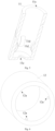
- the present invention provides a releasing mechanism 10 for producing an aerosol generating device which is provided with a heating body 30.
- the heating body 30 is inserted into an aerosol-forming substrate 20 placed on the releasing mechanism.
- the releasing mechanism comprises a rotary portion 11 on which the aerosol-forming substrate 20 is placed.
- a specific shape of the rotary portion 11 is not limited as long as the aerosol-forming substrate 20 can be placed thereon.
- the rotary portion 11 is a cavity, and the rotary portion 11 has a cylindrical shape as a whole, and has an accommodating chamber 11a.
- it may be of other shapes, for example, it has a disk body on which two clamping portions are convexly formed, and the aerosol-forming substrate is clamped by the clamping portions, so that the aerosol-forming substrate can also be placed on the rotary portion.
- a specific material of the rotary portion 11 is not limited, and for example, the rotary portion 11 can be formed from a high temperature resistant material such as metal, ceramic or high molecular material.
- the rotary portion 11 of the present invention is rotatably connected to the aerosol generating device between a first position and a second position.
- the aerosol-forming substrate 20 and the heating body 30 of the present invention are relatively moved in a circumferential direction (shown in a Z direction in Fig. 1 ) during switching from the first position to the second position.
- the aerosol-forming substrate 20 When a user is suctioning, the aerosol-forming substrate 20 is placed in the accommodating chamber 11a of the rotary portion 11, and the heating body 30 is inserted into the aerosol-forming substrate 20. When the rotary portion 11 is in the first position, the aerosol-forming substrate 20 is in contact with the heating body 30.
- the aerosol-forming substrate 20 has a first axial position with respect to the heating body 30, and the heating body 30 is controlled to heat the aerosol-forming substrate 20 to generate an aerosol for the user to suction.
- the rotary portion 11 When the user completes suctioning, the rotary portion 11 is controlled to be rotationally switched from the first position to the second position along the circumferential direction (shown in the Z direction in Fig. 1 ) with respect to the aerosol generating device before the aerosol-forming substrate 20 is pulled out.
- the rotary portion 11 can perform a clockwise rotation, perform a counterclockwise rotation, or perform the clockwise rotation and the counterclockwise rotation alternately along the circumferential direction.
- the aerosol-forming substrate 20 is in contact with and in connection with the heating body 30, and the aerosol-forming substrate 20 and the heating body 30 are relatively movable in the circumferential direction (shown in the Z direction in Fig. 1 ).
- the aerosol-forming substrate 20 In the second position, the aerosol-forming substrate 20 has a second axial position with respect to the heating body 30.
- the first axial position is the same as the second axial position.
- the aerosol-forming substrate and the heating body have no relative movement in an axial direction during switching from the first position to the second position.
- the rotary portion 11 can be prevented from applying an axial force to the heating body 30 during the rotation and thus it is advantageous for stabilizing the connection of the heating body 30 with the aerosol generating device and extending the life of the heating body 30.
- the heating body 30 and the aerosol-forming substrate 20 are relatively moved in the circumferential direction and have no relative movement in the axial direction, a high temperature part of the heating body 30 (a tip end part of the heating body 30) can be prevented from coming into contact with the releasing mechanism, so that aging of the releasing mechanism is delayed, and the life of the releasing mechanism is extended.
- the aerosol-forming substrate 20 has the first axial position with respect to the heating body 30 in the first position; the aerosol-forming substrate 20 has the second axial position with respect to the heating body 30 in the second position, and the first axial position is the same as the second axial position. That is, both in the first position and in the second position, the aerosol-forming substrate 20 is in contact with the heating body 30 and there is no relative movement in the axial direction.
- the rotary portion 11 rotates along the circumferential direction, and the heating body 30 remains stationary; in other embodiments, the heating body may rotate along the circumferential direction, and the rotary portion 11 may remain stationary, as long as in the second position, the aerosol-forming substrate 20 and the heating body 30 are relatively moved in the circumferential direction.
- the heating body may be rotated synchronously with the aerosol generating device at which the heating body is located, or alternatively, the heating body also may be rotated while the aerosol generating device at which the heating body is located may remain stationary.
- a specific type of the aerosol-forming substrate 20 of the present invention is not limited, as long as it can generate an aerosol for the user to suction after being heated by the heating body 30.
- the aerosol-forming substrate 20 can be heated but not burned during the heating body 30 heating the aerosol-forming substrate 20.
- the aerosol-forming substrate 20 is a solid aerosol-forming substrate containing a tobacco component, and the aerosol-forming substrate 20 is wrapped by an outer package (for example, an aluminum foil layer).
- a specific shape of the heating body 30 is not limited.
- the heating body 30 has a columnar shape with a circular cross section.
- the heating body 30 may have a quadrilateral, triangular or polygonal cross section.
- the aerosol-forming substrate 20 is more easily released from the heating body 30 during the relative movement in circumferential direction between the heating body 30 and the aerosol-forming substrate 20.
- the amount of the aerosol-forming substrate 20 remaining on the heating body 30 is less, which is more advantageous for the user to clean the aerosol generating device.
- a specific material of the heating body 30 is not limited, as long as it can generate heat after being energized, so as to heat the aerosol-forming substrate 20 to generate an aerosol.
- the material of the heating body 30 includes ceramic.
- the aerosol-forming substrate 20 is rotatable to the second position along the circumferential direction in synchronization with the rotary portion 11. At the same time, in the second position, the aerosol-forming substrate 20 is rotatable along the circumferential direction in synchronization with the rotary portion 11. In other embodiments, in the second position, the aerosol-forming substrate may not rotate synchronously with the rotary portion along the circumferential direction, as long as the aerosol-forming substrate and the heating body are relatively movable in the circumferential direction. In this embodiment, the aerosol-forming substrate 20 is subjected to a radial pressing force in the second position.
- the aerosol-forming substrate 20 and the heating body 30 are adhered together after the aerosol-forming substrate 20 is heated by the heating body 30, therefore under the radial pressing force, on one hand, an outer package of the aerosol-forming substrate 20 may be rotated along the circumferential direction in synchronization with the rotary portion 11 and the aerosol-forming substrate 20 is brought to move with respect to the heating body 30; and on the other hand, the aerosol-forming substrate 20 is not easily separated from the outer package.
- the aerosol-forming substrate 20 is not synchronously rotated while the outer package of the aerosol-forming substrate 20 is prevented from rotating synchronously with the rotary portion 11 along the circumferential direction. Therefore, the radial pressing force to which the aerosol-forming substrate 20 is subjected facilitates generating a relative movement of the aerosol-forming substrate 20 with respect to the heating body 30.
- the amount of the aerosol-forming substrate 20 remaining on the heating body 30 is less, which is more advantageous for the user to clean the aerosol generating device, when the aerosol-forming substrate 20 is pulled out from the heating body 30 along the axial direction after the aerosol-forming substrate 20 is rotated by a sufficient distance along the circumferential direction in synchronization with the rotary portion 11, that is, after the aerosol-forming substrate 20 is moved by a sufficient distance along the circumferential direction from the heating body 30, under the radial pressing force.
- a pressing mechanism for applying the radial pressing force to the aerosol-forming substrate is disposed on the rotary portion.
- the pressing mechanism is a pressing elastic piece disposed to face the aerosol-forming substrate.
- the pressing elastic piece is deformed after being pressed so as to apply the radial pressing force to the aerosol-forming substrate.
- the pressing elastic piece is disposed around the aerosol-forming substrate 20, and an outer surface of the rotary portion 11 at least partially comprises the pressing elastic piece. That is, a part of the outer surface of the rotary portion 11 is made from the pressing elastic piece.
- At least one first through-hole 11f communicating with the accommodating chamber 11a of the rotary portion 11 is disposed on the rotary portion 11.
- the outer surface of the rotary portion 11 is provided with a pressing mechanism 13 extending in the axial direction (shown in an X direction in Fig. 1 ) which coincides with an inserting direction of the heating body 30.
- the pressing mechanism 13 may not extend in the axial direction.
- a specific shape of the pressing mechanism 13 is not limited as long as the radial pressing force can be applied to the aerosol-forming substrate 20.
- the pressing mechanism 13 has a sheet shape.
- the pressing mechanism 13 is connected to the rotary portion 11, and one end of the pressing mechanism 13 is inserted into the first through-hole 11f along the radial direction (shown in a Y direction in Fig. 1 ) to apply the radial pressing force to the aerosol-forming substrate 20.
- the pressing mechanism 13 When the user completes suctioning, before the aerosol-forming substrate 20 is pulled out, the pressing mechanism 13 is operable to be inserted into the first through-hole 11f along the radial direction so as to press the aerosol-forming substrate 20, and the pressing mechanism 13 clamps the aerosol-forming substrate 20 such that the aerosol-forming substrate 20 is subjected to the radial pressing force under the pressing mechanism 13.
- the rotary portion 11 is then gripped to be switched from the first position to the second position along the circumferential direction.
- the aerosol-forming substrate 20 is connected to contacted with the heating body 30.
- the aerosol-forming substrate 20 is rotated in synchronization with the rotary portion 11, and the aerosol-forming substrate 20 and the heating body 30 are relatively moved along the circumferential direction, such that the aerosol-forming substrate 20 is released from the heating body 30.
- the releasing mechanism 10 of this embodiment further comprises a first case 12.
- the first case 12 is sleeved on the rotary portion 11, and is movable along the axial direction to press the pressing mechanism 13 into the first through-hole 11f. That is, in this embodiment, when the user completes suctioning, before the aerosol-forming substrate 20 is pulled out, the first case 12 is operable to move along the axial direction to press the pressing mechanism 13 into the first through-hole 11f so as to press the aerosol-forming substrate 20, and the aerosol-forming substrate 20 is subjected to the radial pressing force by the pressing mechanism 13.
- An axial movement direction of the first case 12 is not limited.
- the first case 12 may be axially moved along a direction which coincides with an inserting direction of the heating body 30, or may be axially moved along a direction that opposites to the inserting direction of the heating body 30, as long as the first case 12 can press the pressing mechanism 13 into the first through-hole 11f after the axial movement.
- the direction of axial movement of the first case 12 is opposite to the inserting direction of the heating body 30.
- the first case 12 in the first position, the first case 12 is sleeved on the rotary portion 11 and is unable to be disengaged from the rotary portion 11 along the axial direction, and in the second position, the first case 12 is movable along the axial direction to press the pressing mechanism 13 into the first through-hole 11f.
- the first case 12 can be connected to the rotary portion 11 in the axial direction by a spring (not shown.), and along the axial direction, one end of the spring is connected to the rotary portion 11 and the other end of the spring is connected to the first case 12.
- connection manners may be used as long as the following conditions are met: in the first position, the first case 12 is sleeved on the rotary portion 11 and is unable to be disengaged from the rotary portion 11 along the axial direction, and in the second position, the first case 12 is movable along the axial direction to press the pressing mechanism 13 into the first through-hole 11f.
- the rotary portion 11 comprises an abutting surface.
- a portion between one end and other end of the pressing mechanism 13 is abutted against the abutting surface, and the other end of the pressing mechanism 13 is connected to the rotary portion 11 by an elastic element 14.
- the pressing mechanism 13 can perform a lever movement with an intersection point, where the portion between the one end and the other end of the pressing mechanism 13 is abutted against the abutting surface of the rotary portion 11, as a fulcrum.
- the first case 12 is released after the rotary portion 11 is rotated by a certain distance along the circumferential direction, and then the first case 12 is returned back along the direction which coincides with the inserting direction of the heating body 30 under an elastic force of the elastic element 14.
- the pressing mechanism 13 also can be returned back to be separated from the aerosol-forming substrate 20 along the radial direction such that the user can pull out the aerosol-forming substrate 20 at this time.
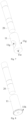
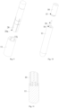
- the pressing mechanism 13 is a plurality of pressing mechanisms. As shown in Fig. 3 , four pressing mechanisms 13 are equally spaced apart along the circumferential direction, and the pressing mechanisms 13 also may be unequally spaced apart. Referring to Fig. 2 and Fig. 3 , in this embodiment, the elastic element 14 is sleeved on the outer surface of the rotary portion 11 and clamps the other end of the pressing mechanism 13.
- the pressing mechanism 13 is provided with an accommodating groove 13c for accommodating the elastic element 14.
- a specific material of the elastic element 14 is not limited and may be a material such as elastic steel or highly elastic silicone.
- a material of the first case 12 is not limited and may be metal or plastic.
- the material of the pressing mechanism 13 may be high temperature resistant metal, ceramic or high molecular material.
- the pressing mechanism 13 has a first convex portion 13b extending along the radial direction, and the first convex portion 13b is abutted against an inner wall of the first case12 along the axial direction.
- An acting force is applied to the first convex portion 13b of the pressing mechanism 13 when the first case 12 moves along the axial direction, which is advantageous for inserting the pressing mechanism 13 into the first through-hole 11f along the radial direction to press the aerosol-forming substrate 20.
- a portion of the first convex portion 13b facing the first case 12 has a first inclined surface 13ba and a second inclined surface 13bc.
- the first inclined surface 13ba is tightly engaged with the first case 12 along the axial direction
- the second inclined surface 13bc is tightly engaged with the first case 12 along the radial direction.
- Such design is advantageous for applying an acting force to the pressing mechanism 13 in the axial direction by the first case 12 so as to drive the pressing mechanism 13 to be inserted into the first through-hole 11f along the radial direction.
- the abutting surface of the rotary portion 11 is provided with a second convex portion 11b, and a portion between the one end and the other end of the pressing mechanism 13 is provided with a first concave portion 13a against which the second convex portion 111b is abutted.
- the second convex portion 11b serves as a fulcrum for a lever movement of the lever mechanism 13.
- the abutting surface of the rotary portion 11 is provided with a first concave portion, and a portion between the one end and the other end of the pressing mechanism 13 is provided with a second convex portion which is abutted against the first concave portion.
- the pressing mechanism 13 can also perform a lever movement when one of the abutting surface of the rotary portion 11 and a portion between the one end and the other end of the pressing mechanism 13 is provided with a convex portion and the other is a smooth surface.
- this embodiment provides the radial pressing force to the aerosol-forming substrate 20 by operating the pressing mechanism 13.
- the pressing mechanism 13 When the aerosol-forming substrate 20 is inserted into the accommodating chamber 11a of the rotary portion 11, that is, when the rotary portion 11 is in the first position, the pressing mechanism 13 will not provide the radial pressing force to the aerosol-forming substrate 20. It can be ensured that the process of inserting the aerosol-forming substrate 20 into the accommodating chamber 11a of the rotary portion is smooth and the resistance is small.
- the pressing mechanism 13 is further operated to provide the radial pressing force to the aerosol-forming substrate 20, so that the aerosol-forming substrate 20 can rotate synchronously with the rotary portion 11. It is advantageous for the relative movement of aerosol-forming substrate 20 with respect to the heating body 30 along the circumferential direction.
- the elastic piece When the aerosol-forming substrate 20 is inserted into the accommodating chamber 11a of the rotary portion 11, the elastic piece is pressed to move toward a chamber wall of the accommodating chamber 11a of the rotary portion 11 along an radial direction, so as to facilitate inserting the aerosol-forming substrate 20 into the accommodating chamber 11a of the rotary portion 11 smoothly.
- the elastic piece After the aerosol-forming substrate 20 is inserted into the heating body 30 and completely passes through the elastic piece, the elastic piece is returned back and applies the radial pressing force to the aerosol-forming substrate 20 so that the aerosol-forming substrate 20 can rotate synchronously with the rotary portion 11
- the elastic piece extends along an axial direction.
- the elastic piece will be pressed to produce an inclined surface when the aerosol-forming substrate 20 is inserted into the accommodating chamber 11a of the rotary portion 11, and the presence of the inclined surface allows the aerosol-forming substrate 20 to be smoothly inserted into the accommodating chamber 11a.
- the elastic piece also will be pressed to produce an inclined surface when the aerosol-forming substrate 20 is pulled out from the accommodating chamber 11a, and the presence of the inclined surface allows the aerosol-forming substrate 20 to be smoothly pulled out from the accommodating chamber 11a.
- the elastic piece has a first end and a second end which are respectively connected to the wall of the rotary portion 11, a portion between the first end and the second end is radially protruded outward along a direction from the first end to the second end, and a surface area of a top of the portion radially protruded outward is smaller than a surface area of the first end and a surface area of the second end respectively. That is, a contact area of the top of the portion of the elastic piece radially protruded outward with the aerosol-forming substrate 20 is smaller.
- the radial pressing force between the top of the portion of the elastic piece radially protruded outward and the aerosol-forming substrate 20 can be increased, and the aerosol-forming substrate 20 can be clamped better by the top of the portion of the elastic piece radially protruded outward, which is advantageous for releasing the aerosol-forming substrate 20 from the heating body 30.
- the releasing mechanism 10 of this embodiment further comprises a first case 12 which is sleeved on the rotary portion 11 and is movable along the axial direction, which coincides with the inserting direction of the heating body 30, to drive the rotary portion 11 to rotate along the circumferential direction.
- a specific implementation of the first case 12 to drive the rotary portion 11 to move along the circumferential direction is not limited.
- an outer surface of the rotary portion 11 is provided with three spiral grooves 11c extending along the axial direction, and three third convex portions 12a are disposed within a case wall of the first case 12.
- the third convex portions 12a are disposed in the spiral grooves 11c and are slidable within the spiral grooves 11c.
- an outer surface of the rotary portion is provided with at least one spiral groove extending along the axial direction, and at least one third convex portion is disposed within a case wall of the first case; or alternatively the outer surface of the rotary portion is provided with the at least one third convex portion, and an inner surface of the case wall of the first case is provided with the at least one spiral groove extending along the axial direction; the third convex portion is disposed in the spiral groove and is slidable within the spiral groove.
- the third convex portion 12a is a plurality of third convex portions spaced apart along the same circumferential direction, which is more advantageous for driving the rotary portion 11 to rotate along the circumferential direction.
- third convex portions may not be spaced apart along the same circumferential direction, as long as the third convex portions slide within the spiral grooves to drive the rotary portion to rotate along the circumferential direction during movement of the first case along the axial direction.
- the rotary portion 11 is in the first position and the rotary portion 11 is subjected to the radial pressing force while the aerosol-forming substrate 20 is inserted into the accommodating chamber 11a of the rotary portion 11.
- the rotary portion 11 may not be subjected to the radial pressing force when the rotary portion 11 is in the first position, which is advantageous for smoothly inserting the aerosol-forming substrate 20 into the heating body 30.
- the aerosol-forming substrate 20 is subjected to the radial pressing force while the rotary portion 11 is switched from the first position to the second position. That is, the radial pressing force, to which the rotary portion 11 is subjected, is generated by a circumferential movement of the rotary portion 11.
- a portion of the rotary portion 11 adjacent to the heating body 30 is provided with at least one second through-hole 11g communicating with the accommodating chamber 11a of the rotary portion 11, and the aerosol-forming substrate 20 is exposed by the second through-hole 11g.
- two second through-holes 11g communicating with the accommodating chamber 11a of the rotary portion 11 are disposed on the rotary portion 11. After the user completes suctioning, the aerosol-forming substrate 20 is pinched and clamped at the second through-hole 11g by a user's fingers.
- the aerosol-forming substrate 20 is rotated in synchronization with the rotary portion 11 by the radial pressing force applied by the fingers, and the rotary portion 11 is switched from the first position to the second position. After rotating by a certain distance, the fingers leave the second through-hole 11g and pull out the aerosol-forming substrate 20 from the accommodating chamber 11a of the rotary portion 11.
- no convex portion is provided when the aerosol-forming substrate 20 is inserted into the accommodating chamber 11a of the rotary portion 11, that is, when the rotary portion 11 is in the first position.
- the process of inserting the aerosol-forming substrate 20 into the accommodating chamber 11a of the rotary portion 11 is smooth, and the resistance is small.
- a pressing mechanism is disposed at the second through-hole for applying the radial pressing force to the aerosol-forming substrate 20 along the radial direction.
- a specific shape and arrangement of the pressing mechanism can be referred to the description of the first embodiment, and the details are not described herein again.
- an outer surface of the rotary portion 11 is provided with a gear 11h extending along the circumferential direction, and a power source is disposed on the releasing mechanism 10 for driving the gear 11h to rotate along the circumferential direction.
- the gear 11h may be driven to be rotated along the circumferential direction by an electric motor or a gear-rack drive, and then the rotary portion 11 is driven to be switched from the first position to the second position.
- a chamber wall of the accommodating chamber 11a of the rotary portion 11 is also provided with at least one convex portion 11d for applying a radial pressing force to the aerosol-forming substrate 20.
- the arrangement and working principle of the convex portion 11d can be referred to the description of the second embodiment, and the details are not described herein again.
- the movement of the aerosol-forming substrate 20 in the circumferential direction is restricted after the aerosol-forming substrate 20 is placed on the rotary portion 11 along an axial direction, which coincides with an extending direction of the heating body 30.
- an inner wall of the accommodating chamber 11a of the rotary portion 11 is provided with at least one fourth convex portion 11j extending along the axial direction, which coincides with the extending direction of the heating body 30.
- Four fourth convex portion 11j spaced apart along the circumferential direction are shown. In other embodiments, other numbers of the fourth convex portion 11j may be selected.
- the outer surface of the aerosol-forming substrate 20 is provided with at least one concave portion 20a extending along the axial direction.
- the fourth convex portion 11j is inserted into the second concave portion 20a along the axial direction.
- the aerosol-forming substrate 20 can also rotate along the circumferential direction in synchronization with the rotary portion 11 when the rotary portion 11 is rotationally switched from the first position to the second position.
- the inner wall of the accommodating chamber of the rotary portion is provided with at least one second concave portion extending along the axial direction, which coincides with the extending direction of the heating body.
- the outer surface of the aerosol-forming substrate is provided with at least one fourth convex portion extending along the axial direction, and the fourth convex portion is inserted in the second concave portion along the axial direction.
- the second concave portion and the fourth convex portion may not extend along the axial direction, as long as the movement of aerosol-forming substrate along the circumferential direction can be restricted after the aerosol-forming substrate is placed on the rotary portion along the axial direction.
- the inner wall of the accommodating chamber of the rotary portion is provided with the second concave portion
- the outer surface of the aerosol-forming substrate is provided with the fourth convex portion.
- the fourth convex portion and the second concave portion are engaged, and the movement of the aerosol-forming substrate along the circumferential direction is restricted after being placed on the rotary portion along the axial direction.
- no convex portion is provided when the aerosol-forming substrate 20 is inserted into the accommodating chamber 11a of the rotary portion 11, that is, when the rotary portion 11 is in the first position.
- the process of inserting the aerosol-forming substrate 20 into the accommodating chamber 11a of the rotary portion 11 is smooth, and the resistance is small.
- the convex portion disposed on the inner chamber wall of the accommodating chamber 11a of the rotary portion 11 is an elastic piece
- the elastic piece is provided with a deformation sensor for detecting the aerosol-forming substrate 20 inserted into the accommodating chamber 11a in accordance with the deformation of the elastic piece. It is possible to prevent a minor from operating the heating body 30 by mistake after the deformation sensor is provided.
- the heating body 30 is heated only when the aerosol-forming substrate 20 is inserted into the accommodating chamber 11a of the rotary portion. Thus, a protective effect is achieved.
- the rotary portion 11 is provided with a hole 11e through which the heating body 30 is inserted, and the hole 11e has an aperture which is not smaller than an outer diameter of the heating body 30.
- the aperture of the hole 11e is larger than the outer diameter of the heating body 30, after the releasing mechanism 10 of the above embodiment is rotationally connected to the aerosol generating device, the heating body 30 heats the aerosol-forming substrate 20 to generate an aerosol and then the inside of the accommodating chamber 11a of the rotary portion communicates with the outside atmosphere through the hole 11e so that the user can suction the aerosol generated by the aerosol-forming substrate 20.
- this embodiment provides an aerosol generating device, comprising: the heating body 30; and the releasing mechanism 10 of any one of the above embodiments.
- the rotary portion 11 is connected to the aerosol generating device rotatably between the first position and the second position, and is limited to the aerosol generating device along the axial direction.
- the heating body 30 is inserted into the accommodating chamber 11a of the rotary portion 11.
- the aerosol generating device further comprises a body portion 40 on which the heating body 30 is disposed via a heating body holder 31.
- the rotary portion 11 is disposed on the body portion 40, connected with the body portion 40 rotatably in the circumferential direction, and has no relative movement in the axial direction with the body portion 40.
- the rotary portion 11 rotates along the circumferential direction, and the body portion 40 remains stationary; or alternatively, the body portion 40 rotates along the circumferential direction and the heating body 30 rotates synchronously with the body portion 40 while the rotary portion 11 remains stationary. Both cases can achieve a relative movement of the aerosol-forming substrate 20 with respect to the heating body 30 in the circumferential direction (shown in the Z direction in Fig. 1 ).
- the rotary portion disposed on the body portion is connected to the heating body rotatably in the circumferential direction, such as with the heating body holder 31, and has no relative movement in the axial direction with the heating body.
- the rotary portion 11 rotates along the circumferential direction, and the heating body 30 remains stationary; or alternatively, the heating body 30 rotates along the circumferential direction and the body portion does not rotate synchronously with the heating body while the rotary portion 11 remains stationary. Both cases can achieve a relative movement of the aerosol-forming substrate 20 with respect to the heating body 30 in the circumferential direction (shown in the Z direction in Fig. 1 ).
- a first slot 15 is disposed on the releasing mechanism 10
- a second slot 16 is disposed on the body portion 40.
- the first slot 15 and the second slot 16 are engaged to engage the rotary portion 11 to the body portion 40.
- the rotary portion 11 and the body portion 40 may be engaged in other forms, as long as the rotary portion 11 is engaged to the body portion 40.
- a control circuit 41, an indicator light 45, a button 44, a battery 42, and a charging control circuit 43 are also disposed on the body portion 40.
- the heating body 30 is connected to the control circuit 41 connected to the battery 42, and the charging control circuit 43 is connected to the battery 42 and the control circuit 41. Start and stop of the heating body 30 can be controlled by pressing the button 44.
- the indicator light 45 on the button 44 can indicate an operating status of the aerosol generating device.
- the control circuit 41 and the heating body 30 cooperate to control the temperature of the heating body 30 between 200 degrees Centigrade and 500 degrees Centigrade, which ensures that the heated aerosol-forming substrate 20 can volatilize a stable aerosol.
- the charging control circuit 43 can perform a control for charging the battery 42.
- the aerosol-forming substrate 20 is inserted into the accommodating chamber 11a of the rotary portion 11, and the heating body 30 is inserted into the aerosol-forming substrate 20.
- the rotary portion 11 is in the first position, the aerosol-forming substrate 20 is in contact with the heating body 30, and both remain relatively stationary.
- the heating body 30 is controlled to heat the aerosol-forming substrate 20 to generate the aerosol for the user to suction.
- the rotary portion 11 is controlled to be rotationally switched from the first position to the second position along the circumferential direction before the aerosol-forming substrate 20 is pulled out.
- the aerosol-forming substrate 20 is connected to and contacted with the heating body 30, and the aerosol-forming substrate 20 and the heating body 30 are relatively moved in the circumferential direction.
- the aerosol-forming substrate 20 changes from being adhered to the heating body 30 to being released from the heating body 30 during the relative movement in circumferential direction between the aerosol-forming substrate 20 and the heating body 20.
- the aerosol-forming substrate 20 can be easily pulled out from the heating body 30 by the user, and it is convenient to use and also convenient for the user to clean the aerosol generating device.
- the surface of the heating body 30 is provided with a glaze layer in order to make the relative movement of the heating body 30 with the aerosol-forming substrate 20 in the circumferential direction smoother.
- the glaze layer is disposed, the resistance suffered when the heating body 30 and the aerosol-forming substrate 20 are relatively moved in the circumferential direction is smaller, which is advantageous for releasing the aerosol-forming substrate 20 from the heating body 30.
- the present invention provides a method of releasing the aerosol-forming substrate 20, comprising: causing the aerosol-forming substrate 20 being rotatable from the first position to the second position along the circumferential direction with respect to the heating body 30 after the heating body 30 of an aerosol generating device is inserted into the aerosol-forming substrate 20, wherein the aerosol-forming substrate 20 and the heating body 30 are relatively movable in the circumferential direction during switching from the first position to the second position.
- the aerosol-forming substrate 20 In the first position, the aerosol-forming substrate 20 is connected to and contacted with the heating body 30 and has a first axial position with respect to the heating body 30; in the second position, the aerosol-forming substrate is connected to and contacted with the heating body 30 and has a second axial position with respect to the heating body 30, and the aerosol-forming substrate 20 and the heating body 30 are relatively moved in the circumferential direction.
- the first axial position is the same as the second axial position.
- the aerosol-forming substrate 20 being adhered to the heating body 30 is released from the heating body 30 during the relative movement in circumferential direction between the aerosol-forming substrate 20 and the heating body 30.
- the aerosol-forming substrate 20 can be easily removed from the heating body 30 by the user, and it is convenient to use.
- this embodiment uses the releasing mechanism described in any one of the above embodiments to release the aerosol-forming substrate 20.
- the aerosol-forming substrate 20 can be synchronously rotated to the second position along the circumferential direction with the rotary portion 11, so that the aerosol-forming substrate 20 can rapidly come into being relatively moved in the circumferential direction with respect to the heating body 30 to release.
- the aerosol-forming substrate 20 is subjected to the radial pressing force while the rotary portion 11 is switched from the first position to the second position. That is, in the first position, the rotary portion 11 is not subjected to the radial pressing force, which is advantageous for smoothly inserting the aerosol-forming substrate 20 into the heating body 30.
- the aerosol-forming substrate 20 is subjected to the radial pressing force while the rotary portion 11 is switched from the first position to the second position. Under the radial pressing force, the aerosol-forming substrate 20 and the heating body 30 are caused to move relative to each other, and the aerosol-forming substrate 20 can be smoothly removed.
- the present invention also provides a smoking producing article comprising the aerosol-forming substrate 20 which is usable to the above releasing mechanism.
- the movement of the aerosol-forming substrate 20 in the circumferential direction is restricted after the aerosol-forming substrate 20 is placed on the rotary portion 11 of the releasing mechanism along an axial direction, which coincides with the extending direction of the heating body 30.
- the outer surface of the aerosol-forming substrate is provided with the fourth convex portion or the second concave portion 20a. Further descriptions of the aerosol-forming substrate 20 can be referred to the fifth embodiment, and the details are not described herein again.
- the aerosol-forming substrate 20 of the smoking producing article is inserted into the rotary portion 11 of the releasing mechanism along the axial direction by the fourth convex portion or the second concave portion 20a, the aerosol-forming substrate 20 is also rotatable in synchronization with the rotary portion 11 in the circumferential direction when the rotary portion 11 is rotationally switched from the first position to the second position.
Landscapes
- Containers And Packaging Bodies Having A Special Means To Remove Contents (AREA)
- Disinfection, Sterilisation Or Deodorisation Of Air (AREA)
- Catching Or Destruction (AREA)
Applications Claiming Priority (2)
| Application Number | Priority Date | Filing Date | Title |
|---|---|---|---|
| CN201810060869.3A CN108451028B (zh) | 2018-01-22 | 2018-01-22 | 松脱机构、气雾产生装置、松脱方法及发烟制品 |
| PCT/CN2018/077765 WO2019140749A1 (zh) | 2018-01-22 | 2018-03-01 | 松脱机构、气雾产生装置、松脱方法及发烟制品 |
Publications (4)
| Publication Number | Publication Date |
|---|---|
| EP3744192A1 EP3744192A1 (en) | 2020-12-02 |
| EP3744192A4 EP3744192A4 (en) | 2021-10-27 |
| EP3744192B1 true EP3744192B1 (en) | 2025-01-08 |
| EP3744192C0 EP3744192C0 (en) | 2025-01-08 |
Family
ID=63238403
Family Applications (1)
| Application Number | Title | Priority Date | Filing Date |
|---|---|---|---|
| EP18901048.1A Active EP3744192B1 (en) | 2018-01-22 | 2018-03-01 | Releasing mechanism, aerosol generating device, releasing method, and smoke producing article |
Country Status (7)
| Country | Link |
|---|---|
| US (1) | US11559082B2 (pl) |
| EP (1) | EP3744192B1 (pl) |
| JP (1) | JP6876871B2 (pl) |
| KR (1) | KR102416544B1 (pl) |
| CN (2) | CN108451028B (pl) |
| PL (1) | PL3744192T3 (pl) |
| WO (1) | WO2019140749A1 (pl) |
Families Citing this family (35)
| Publication number | Priority date | Publication date | Assignee | Title |
|---|---|---|---|---|
| WO2019238812A1 (en) * | 2018-06-14 | 2019-12-19 | Philip Morris Products S.A. | Retracable heater for aerosol-generating device |
| CN108783605B (zh) | 2018-08-07 | 2024-02-13 | 上海新型烟草制品研究院有限公司 | 一种松脱机构及气雾产生装置 |
| HUE070438T2 (hu) * | 2018-10-12 | 2025-06-28 | Jt Int Sa | Aeroszolképzõ eszköz és hevítõkamra |
| KR20220002288A (ko) * | 2019-04-29 | 2022-01-06 | 필립모리스 프로덕츠 에스.에이. | 가열 구역 절연부를 갖는 에어로졸 발생 장치 |
| CN112335941A (zh) * | 2019-08-07 | 2021-02-09 | 吴高升 | 一种具有转动功能的电加热装置 |
| CN110301683A (zh) * | 2019-08-09 | 2019-10-08 | 深圳市讴可电子科技有限公司 | 一种电子烟的控制方法、装置及电子烟 |
| US20220295894A1 (en) | 2019-08-28 | 2022-09-22 | Philip Morris Products S.A. | Flared susceptor heating arrangement for aerosol-generating device |
| EP4025082A1 (en) * | 2019-09-06 | 2022-07-13 | JT International SA | Aerosol generation device and heating chamber therefor |
| CN110584215B (zh) * | 2019-09-26 | 2024-10-15 | 深圳麦时科技有限公司 | 烘烤烟具 |
| KR102363396B1 (ko) * | 2019-10-16 | 2022-02-15 | 주식회사 케이티앤지 | 추출기를 포함하는 에어로졸 생성 장치 |
| KR20260036608A (ko) | 2020-01-29 | 2026-03-17 | 필립모리스 프로덕츠 에스.에이. | 에어로졸 발생 장치용 조정 가능한 유지 부재 |
| KR102793114B1 (ko) * | 2020-02-27 | 2025-04-09 | 니뽄 다바코 산교 가부시키가이샤 | 흡연 시스템, 디바이스, 및 소모품 |
| CN116268583A (zh) * | 2020-02-28 | 2023-06-23 | 深圳御烟实业有限公司 | 一种双向退烟机构及气溶胶产生装置 |
| WO2021186880A1 (ja) * | 2020-03-18 | 2021-09-23 | 日本たばこ産業株式会社 | 吸引装置、情報処理方法、及びプログラム |
| CN111359884B (zh) * | 2020-03-27 | 2024-06-07 | 陕西中烟工业有限责任公司 | 用于卷烟机中梗丝分选通道的自动调节装置 |
| KR102535305B1 (ko) * | 2020-06-17 | 2023-05-22 | 주식회사 케이티앤지 | 에어로졸 생성 장치 |
| CN111904030B (zh) * | 2020-06-29 | 2025-05-30 | 深圳市吉迩科技有限公司 | 提烟机构及气溶胶产生装置 |
| EP4260728B1 (en) * | 2020-12-11 | 2025-08-13 | Japan Tobacco Inc. | Flavor inhaler and method for producing flavor inhaler |
| GB202101461D0 (en) * | 2021-02-03 | 2021-03-17 | Nicoventures Trading Ltd | Aerosol provision system |
| EP4321042A4 (en) * | 2021-04-09 | 2025-01-29 | Japan Tobacco Inc. | FLAVOR INHALER AND SMOKING SYSTEM |
| WO2022215256A1 (ja) * | 2021-04-09 | 2022-10-13 | 日本たばこ産業株式会社 | 香味吸引器及び喫煙システム |
| WO2022230087A1 (ja) * | 2021-04-28 | 2022-11-03 | 日本たばこ産業株式会社 | 香味吸引器および喫煙システム |
| WO2022238295A1 (en) | 2021-05-10 | 2022-11-17 | Jt International Sa | Aerosol generation device and set |
| CN113598428A (zh) * | 2021-08-17 | 2021-11-05 | 深圳御烟实业有限公司 | 气溶胶生成装置 |
| WO2023026322A1 (ja) * | 2021-08-23 | 2023-03-02 | 日本たばこ産業株式会社 | エアロゾル生成システム |
| US12419350B2 (en) * | 2021-09-10 | 2025-09-23 | Imperial Tobacco Limited | Aerosol generating apparatus having a push-push mechanism |
| CN113876035B (zh) * | 2021-10-26 | 2023-10-24 | 湖北中烟工业有限责任公司 | 一种具有烟支夹紧装置的烟具 |
| KR20240064687A (ko) * | 2021-11-22 | 2024-05-13 | 니뽄 다바코 산교 가부시키가이샤 | 향미 흡인기 및 향미 흡인 시스템 |
| EP4437881A4 (en) * | 2021-11-22 | 2025-09-10 | Japan Tobacco Inc | AROMA INHALER AND AROMA INHALATION SYSTEM |
| KR102603883B1 (ko) * | 2021-11-26 | 2023-11-20 | 주식회사 케이티앤지 | 에어로졸 발생 장치 및 시스템 |
| CN116210968A (zh) * | 2021-12-02 | 2023-06-06 | 深圳市合元科技有限公司 | 气溶胶生成装置及气溶胶生成装置的控制方法 |
| CN119212578A (zh) | 2022-05-19 | 2024-12-27 | 日本烟草产业株式会社 | 气溶胶生成系统 |
| WO2024018012A1 (en) * | 2022-07-21 | 2024-01-25 | Nicoventures Trading Limited | Aerosol provision device |
| CN220157579U (zh) * | 2023-05-30 | 2023-12-12 | 思摩尔国际控股有限公司 | 气溶胶产生制品及气溶胶生成装置 |
| CN119908524A (zh) * | 2023-10-31 | 2025-05-02 | 深圳麦时科技有限公司 | 气溶胶生成装置 |
Citations (1)
| Publication number | Priority date | Publication date | Assignee | Title |
|---|---|---|---|---|
| EP3718419A1 (en) * | 2017-11-29 | 2020-10-07 | Hubei China Tobacco Industry Co., Ltd. | Axially rotating electric heating device for extracting tobacco |
Family Cites Families (27)
| Publication number | Priority date | Publication date | Assignee | Title |
|---|---|---|---|---|
| FR940447A (fr) * | 1946-02-11 | 1948-12-13 | Fume-cigarette ou cigare | |
| US5878752A (en) * | 1996-11-25 | 1999-03-09 | Philip Morris Incorporated | Method and apparatus for using, cleaning, and maintaining electrical heat sources and lighters useful in smoking systems and other apparatuses |
| ES2312862T3 (es) * | 2003-01-20 | 2009-03-01 | Japan Tobacco Inc. | Paquete para articulos para fumar similares a varillas. |
| JP5362591B2 (ja) * | 2007-03-09 | 2013-12-11 | イーライ リリー アンド カンパニー | 自動注入装置用遅延機構 |
| CN101487101B (zh) | 2008-01-17 | 2011-05-11 | 宝山钢铁股份有限公司 | 一种ct70级连续油管用钢 |
| CN101634001B (zh) | 2008-07-24 | 2011-07-20 | 宝山钢铁股份有限公司 | 一种ct90级连续油管用钢及其制造方法 |
| CN101944682A (zh) * | 2009-07-07 | 2011-01-12 | 技嘉科技股份有限公司 | 连接座总成 |
| KR101057774B1 (ko) * | 2010-12-13 | 2011-08-19 | 신종수 | 전자담배 |
| CA3079706C (en) * | 2011-11-21 | 2023-08-01 | Philip Morris Products S.A. | Ejector for an aerosol-generating device |
| EP2608298B1 (de) | 2011-12-22 | 2018-07-04 | Umicore AG & Co. KG | Elektrokatalysator für Brennstoffzellen sowie Verfahren zu seiner Herstellung |
| MY168355A (en) * | 2011-12-30 | 2018-10-31 | Philip Morris Products Sa | Aerosol generating device with improved temperature distribution |
| AR089607A1 (es) * | 2012-01-03 | 2014-09-03 | Philip Morris Products Sa | Sistema de suministro de energia para un dispositivo portatil generador de aerosol |
| CN202528361U (zh) * | 2012-01-19 | 2012-11-14 | 江苏益尔机电有限公司 | 用于双模轮胎定型硫化机的快速更换模具机构 |
| WO2015155289A1 (en) * | 2014-04-10 | 2015-10-15 | Philip Morris Products S.A. | Aerosol-generating device with helix-shaped heater |
| CN104544569B (zh) * | 2014-05-30 | 2017-10-31 | 深圳麦克韦尔股份有限公司 | 电子烟 |
| WO2016023172A1 (zh) * | 2014-08-12 | 2016-02-18 | 刘水根 | 一种烟草蒸发器 |
| CN104451427B (zh) | 2014-12-11 | 2016-08-24 | 宝鸡石油钢管有限责任公司 | 一种无焊接缺陷连续油管及制造方法 |
| WO2016124550A1 (en) * | 2015-02-06 | 2016-08-11 | Philip Morris Products S.A. | Improved extractor for an aerosol-generating device |
| CN104770895B (zh) * | 2015-03-13 | 2017-08-08 | 云南中烟工业有限责任公司 | 用于烟制品的加热装置以及烟雾发生器 |
| CN205432131U (zh) * | 2015-10-28 | 2016-08-10 | 深圳麦克韦尔股份有限公司 | 电子烟雾化器 |
| CN205597118U (zh) * | 2016-03-14 | 2016-09-28 | 深圳市合元科技有限公司 | 烟支加热装置及电子烟 |
| CN206025202U (zh) * | 2016-08-30 | 2017-03-22 | 云南中烟工业有限责任公司 | 一种自动退出烟蒂的装置 |
| CN106376975B (zh) | 2016-09-18 | 2023-10-31 | 上海烟草集团有限责任公司 | 气雾产生装置及其使用方法 |
| CN206187398U (zh) * | 2016-11-11 | 2017-05-24 | 陈金柱 | 紧固装置 |
| CN207940349U (zh) * | 2018-01-22 | 2018-10-09 | 上海新型烟草制品研究院有限公司 | 松脱机构、气雾产生装置及发烟制品 |
| JP7266750B2 (ja) * | 2019-08-28 | 2023-04-28 | フィリップ・モーリス・プロダクツ・ソシエテ・アノニム | エアロゾル発生装置のための弾性封止要素 |
| KR20260036608A (ko) * | 2020-01-29 | 2026-03-17 | 필립모리스 프로덕츠 에스.에이. | 에어로졸 발생 장치용 조정 가능한 유지 부재 |
-
2018
- 2018-01-22 CN CN201810060869.3A patent/CN108451028B/zh active Active
- 2018-01-22 CN CN202411187747.2A patent/CN119014593A/zh active Pending
- 2018-03-01 EP EP18901048.1A patent/EP3744192B1/en active Active
- 2018-03-01 KR KR1020207008029A patent/KR102416544B1/ko active Active
- 2018-03-01 JP JP2020517184A patent/JP6876871B2/ja active Active
- 2018-03-01 WO PCT/CN2018/077765 patent/WO2019140749A1/zh not_active Ceased
- 2018-03-01 PL PL18901048.1T patent/PL3744192T3/pl unknown
- 2018-03-01 US US16/652,965 patent/US11559082B2/en active Active
Patent Citations (1)
| Publication number | Priority date | Publication date | Assignee | Title |
|---|---|---|---|---|
| EP3718419A1 (en) * | 2017-11-29 | 2020-10-07 | Hubei China Tobacco Industry Co., Ltd. | Axially rotating electric heating device for extracting tobacco |
Also Published As
| Publication number | Publication date |
|---|---|
| EP3744192A1 (en) | 2020-12-02 |
| CN108451028A (zh) | 2018-08-28 |
| EP3744192A4 (en) | 2021-10-27 |
| JP2021502800A (ja) | 2021-02-04 |
| KR102416544B1 (ko) | 2022-07-05 |
| JP6876871B2 (ja) | 2021-05-26 |
| CN108451028B (zh) | 2024-10-15 |
| CN119014593A (zh) | 2024-11-26 |
| PL3744192T3 (pl) | 2025-04-07 |
| KR20200044047A (ko) | 2020-04-28 |
| WO2019140749A1 (zh) | 2019-07-25 |
| US20200323270A1 (en) | 2020-10-15 |
| EP3744192C0 (en) | 2025-01-08 |
| US11559082B2 (en) | 2023-01-24 |
Similar Documents
| Publication | Publication Date | Title |
|---|---|---|
| EP3744192B1 (en) | Releasing mechanism, aerosol generating device, releasing method, and smoke producing article | |
| EP3818856B1 (en) | Releasing mechanism for an aerosol generating device and corresponding device | |
| JP7096895B2 (ja) | 発熱体用の、プロングを有する掃除ツール | |
| US11849766B2 (en) | Aerosol-generating device | |
| KR102576939B1 (ko) | 기어가 있는 가열 요소용 청소 도구 | |
| CN207940349U (zh) | 松脱机构、气雾产生装置及发烟制品 | |
| JP7395713B2 (ja) | 低温喫煙具 | |
| JP2022508065A (ja) | エアロゾル生成装置 | |
| CN210538933U (zh) | 带旋转门的低温烟具 | |
| CN113876035A (zh) | 一种具有烟支夹紧装置的烟具 | |
| CN209219258U (zh) | 一种气雾产生装置及气雾产生系统 | |
| JP3102406U (ja) | 電気プラグ | |
| CN111165894B (zh) | 一种气雾产生装置 | |
| CN111820473B (zh) | 具有烟支抱紧结构的低温烟具 | |
| WO2020078134A1 (zh) | 一种气雾产生装置及气雾产生系统 | |
| CN208286372U (zh) | 一种松脱机构以及气雾产生装置 | |
| CN215124309U (zh) | 气溶胶产生装置 | |
| CN110584215B (zh) | 烘烤烟具 | |
| CN221410422U (zh) | 一种加热不燃烧器具 | |
| CN111165895B (zh) | 一种气雾产生装置 | |
| CN218527705U (zh) | 一种具有童锁功能的气溶胶发生装置 | |
| CN119632301A (zh) | 一种加热不燃烧器具 |
Legal Events
| Date | Code | Title | Description |
|---|---|---|---|
| STAA | Information on the status of an ep patent application or granted ep patent |
Free format text: STATUS: THE INTERNATIONAL PUBLICATION HAS BEEN MADE |
|
| PUAI | Public reference made under article 153(3) epc to a published international application that has entered the european phase |
Free format text: ORIGINAL CODE: 0009012 |
|
| STAA | Information on the status of an ep patent application or granted ep patent |
Free format text: STATUS: REQUEST FOR EXAMINATION WAS MADE |
|
| 17P | Request for examination filed |
Effective date: 20200310 |
|
| AK | Designated contracting states |
Kind code of ref document: A1 Designated state(s): AL AT BE BG CH CY CZ DE DK EE ES FI FR GB GR HR HU IE IS IT LI LT LU LV MC MK MT NL NO PL PT RO RS SE SI SK SM TR |
|
| AX | Request for extension of the european patent |
Extension state: BA ME |
|
| DAV | Request for validation of the european patent (deleted) | ||
| DAX | Request for extension of the european patent (deleted) | ||
| REG | Reference to a national code |
Ref country code: DE Ref legal event code: R079 Free format text: PREVIOUS MAIN CLASS: A24F0047000000 Ipc: A24F0040400000 Ref country code: DE Ref legal event code: R079 Ref document number: 602018078446 Country of ref document: DE Free format text: PREVIOUS MAIN CLASS: A24F0047000000 Ipc: A24F0040400000 |
|
| A4 | Supplementary search report drawn up and despatched |
Effective date: 20210924 |
|
| RIC1 | Information provided on ipc code assigned before grant |
Ipc: A24F 40/20 20200101ALN20210920BHEP Ipc: A24D 1/20 20200101ALI20210920BHEP Ipc: A24F 40/51 20200101ALI20210920BHEP Ipc: A24F 40/46 20200101ALI20210920BHEP Ipc: A24F 40/40 20200101AFI20210920BHEP |
|
| STAA | Information on the status of an ep patent application or granted ep patent |
Free format text: STATUS: EXAMINATION IS IN PROGRESS |
|
| 17Q | First examination report despatched |
Effective date: 20230720 |
|
| GRAP | Despatch of communication of intention to grant a patent |
Free format text: ORIGINAL CODE: EPIDOSNIGR1 |
|
| STAA | Information on the status of an ep patent application or granted ep patent |
Free format text: STATUS: GRANT OF PATENT IS INTENDED |
|
| INTG | Intention to grant announced |
Effective date: 20241008 |
|
| GRAS | Grant fee paid |
Free format text: ORIGINAL CODE: EPIDOSNIGR3 |
|
| GRAA | (expected) grant |
Free format text: ORIGINAL CODE: 0009210 |
|
| STAA | Information on the status of an ep patent application or granted ep patent |
Free format text: STATUS: THE PATENT HAS BEEN GRANTED |
|
| AK | Designated contracting states |
Kind code of ref document: B1 Designated state(s): AL AT BE BG CH CY CZ DE DK EE ES FI FR GB GR HR HU IE IS IT LI LT LU LV MC MK MT NL NO PL PT RO RS SE SI SK SM TR |
|
| REG | Reference to a national code |
Ref country code: GB Ref legal event code: FG4D |
|
| REG | Reference to a national code |
Ref country code: CH Ref legal event code: EP |
|
| REG | Reference to a national code |
Ref country code: DE Ref legal event code: R096 Ref document number: 602018078446 Country of ref document: DE |
|
| REG | Reference to a national code |
Ref country code: IE Ref legal event code: FG4D |
|
| U01 | Request for unitary effect filed |
Effective date: 20250131 |
|
| U07 | Unitary effect registered |
Designated state(s): AT BE BG DE DK EE FI FR IT LT LU LV MT NL PT RO SE SI Effective date: 20250205 |
|
| U20 | Renewal fee for the european patent with unitary effect paid |
Year of fee payment: 8 Effective date: 20250225 |
|
| PGFP | Annual fee paid to national office [announced via postgrant information from national office to epo] |
Ref country code: PL Payment date: 20250220 Year of fee payment: 8 |
|
| PG25 | Lapsed in a contracting state [announced via postgrant information from national office to epo] |
Ref country code: RS Free format text: LAPSE BECAUSE OF FAILURE TO SUBMIT A TRANSLATION OF THE DESCRIPTION OR TO PAY THE FEE WITHIN THE PRESCRIBED TIME-LIMIT Effective date: 20250408 |
|
| PG25 | Lapsed in a contracting state [announced via postgrant information from national office to epo] |
Ref country code: ES Free format text: LAPSE BECAUSE OF FAILURE TO SUBMIT A TRANSLATION OF THE DESCRIPTION OR TO PAY THE FEE WITHIN THE PRESCRIBED TIME-LIMIT Effective date: 20250108 |
|
| PG25 | Lapsed in a contracting state [announced via postgrant information from national office to epo] |
Ref country code: IS Free format text: LAPSE BECAUSE OF FAILURE TO SUBMIT A TRANSLATION OF THE DESCRIPTION OR TO PAY THE FEE WITHIN THE PRESCRIBED TIME-LIMIT Effective date: 20250508 Ref country code: NO Free format text: LAPSE BECAUSE OF FAILURE TO SUBMIT A TRANSLATION OF THE DESCRIPTION OR TO PAY THE FEE WITHIN THE PRESCRIBED TIME-LIMIT Effective date: 20250408 |
|
| PG25 | Lapsed in a contracting state [announced via postgrant information from national office to epo] |
Ref country code: HR Free format text: LAPSE BECAUSE OF FAILURE TO SUBMIT A TRANSLATION OF THE DESCRIPTION OR TO PAY THE FEE WITHIN THE PRESCRIBED TIME-LIMIT Effective date: 20250108 |
|
| PG25 | Lapsed in a contracting state [announced via postgrant information from national office to epo] |
Ref country code: GR Free format text: LAPSE BECAUSE OF FAILURE TO SUBMIT A TRANSLATION OF THE DESCRIPTION OR TO PAY THE FEE WITHIN THE PRESCRIBED TIME-LIMIT Effective date: 20250409 |
|
| PG25 | Lapsed in a contracting state [announced via postgrant information from national office to epo] |
Ref country code: SM Free format text: LAPSE BECAUSE OF FAILURE TO SUBMIT A TRANSLATION OF THE DESCRIPTION OR TO PAY THE FEE WITHIN THE PRESCRIBED TIME-LIMIT Effective date: 20250108 |
|
| PG25 | Lapsed in a contracting state [announced via postgrant information from national office to epo] |
Ref country code: MC Free format text: LAPSE BECAUSE OF FAILURE TO SUBMIT A TRANSLATION OF THE DESCRIPTION OR TO PAY THE FEE WITHIN THE PRESCRIBED TIME-LIMIT Effective date: 20250108 |
|
| PG25 | Lapsed in a contracting state [announced via postgrant information from national office to epo] |
Ref country code: CZ Free format text: LAPSE BECAUSE OF FAILURE TO SUBMIT A TRANSLATION OF THE DESCRIPTION OR TO PAY THE FEE WITHIN THE PRESCRIBED TIME-LIMIT Effective date: 20250108 |
|
| REG | Reference to a national code |
Ref country code: CH Ref legal event code: H13 Free format text: ST27 STATUS EVENT CODE: U-0-0-H10-H13 (AS PROVIDED BY THE NATIONAL OFFICE) Effective date: 20251023 |
|
| PG25 | Lapsed in a contracting state [announced via postgrant information from national office to epo] |
Ref country code: SK Free format text: LAPSE BECAUSE OF FAILURE TO SUBMIT A TRANSLATION OF THE DESCRIPTION OR TO PAY THE FEE WITHIN THE PRESCRIBED TIME-LIMIT Effective date: 20250108 |
|
| PLBE | No opposition filed within time limit |
Free format text: ORIGINAL CODE: 0009261 |
|
| STAA | Information on the status of an ep patent application or granted ep patent |
Free format text: STATUS: NO OPPOSITION FILED WITHIN TIME LIMIT |
|
| 26N | No opposition filed |
Effective date: 20251009 |
|
| PG25 | Lapsed in a contracting state [announced via postgrant information from national office to epo] |
Ref country code: CH Free format text: LAPSE BECAUSE OF NON-PAYMENT OF DUE FEES Effective date: 20250331 |
|
| PG25 | Lapsed in a contracting state [announced via postgrant information from national office to epo] |
Ref country code: IE Free format text: LAPSE BECAUSE OF NON-PAYMENT OF DUE FEES Effective date: 20250301 |
|
| U20 | Renewal fee for the european patent with unitary effect paid |
Year of fee payment: 9 Effective date: 20260226 |
|
| PGFP | Annual fee paid to national office [announced via postgrant information from national office to epo] |
Ref country code: GB Payment date: 20260323 Year of fee payment: 9 |