EP3744201A1 - Helm und öse - Google Patents
Helm und öse Download PDFInfo
- Publication number
- EP3744201A1 EP3744201A1 EP20176527.8A EP20176527A EP3744201A1 EP 3744201 A1 EP3744201 A1 EP 3744201A1 EP 20176527 A EP20176527 A EP 20176527A EP 3744201 A1 EP3744201 A1 EP 3744201A1
- Authority
- EP
- European Patent Office
- Prior art keywords
- base
- operation member
- helmet
- shutters
- opening
- Prior art date
- Legal status (The legal status is an assumption and is not a legal conclusion. Google has not performed a legal analysis and makes no representation as to the accuracy of the status listed.)
- Granted
Links
Images

Classifications
-
- A—HUMAN NECESSITIES
- A42—HEADWEAR
- A42B—HATS; HEAD COVERINGS
- A42B3/00—Helmets; Helmet covers ; Other protective head coverings
- A42B3/04—Parts, details or accessories of helmets
- A42B3/28—Ventilating arrangements
- A42B3/281—Air ducting systems
- A42B3/283—Air inlets or outlets, with or without closure shutters
Definitions
- the following description relates to a helmet and a grommet.
- a helmet includes a vent to ventilate the inside of the helmet and prevent fogging of an inner surface of a shield.
- the vent is configured to be opened and closed and connects the inside of the helmet and an outer surface of the helmet.
- Japanese Laid-Open Patent Publication No. 10-121317 describes a helmet including recesses extending into a shell of the helmet. A vent connecting the inside and outside of the shell is open in the recess. Further, a base including a connection hole is fitted and fixed to the recess in order to connect the recess and the vent. Then, a vertically pivotal shutter is coupled to the base to open and close the vent.
- Japanese Laid-Open Utility Model Publication No. 2-87027 describes a helmet including a knob that is moved left and right to open and close a vent using a shutter.
- the vent of the helmet is opened and closed by the shutter.
- the helmet needs to include a shutter open-close mechanism. It is desirable that the shutter open-close mechanism has a simplified structure and occupies only a small amount of space.
- the mechanism that pivots the shutter is complicated and requires many parts. This lowers the efficiency for connecting the mechanism to the helmet.
- the helmet of Japanese Laid-Open Utility Model Publication No. 2-87027 uses one shutter to open and close two vents.
- the shutter open-close mechanism occupies a large amount of space.
- Such a shutter open-close mechanism adversely affects the exterior design of the helmet. Therefore, it is desirable that the shutter open-close mechanism occupy less space.
- One object of the following description is to provide a grommet for a vent and a helmet that allow an open-close mechanism of the vent to have a simplified structure that occupies less space.
- a helmet in one general aspect, includes a shell and a grommet.
- the shell has a through hole extending from an outer side of the shell to an inner side of the shell.
- the grommet is arranged on the shell where the through hole is located, and forming a vent that draws outside air into the shell.
- the grommet includes a base, an operation member, and a plurality of shutters.
- the base is coupled to the shell where the through hole is located and the base has an opening at a position overlapping the through hole.
- the operation member is rotatably coupled to the base.
- the plurality of shutters is configured to open and close the opening when the operation member is rotated relative to the base.
- a grommet When the grommet is coupled to a shell of a helmet, the grommet forms a vent in the helmet to draw outside air into the helmet.
- the grommet includes a base, an operation member, and a plurality of shutters.
- the base is configured to be coupled to the shell of the helmet where a through hole is located.
- the base includes an opening that overlaps the through hole when the base is coupled to the shell of the helmet where the through hole is located.
- the operation member is rotatably coupled to the base.
- the plurality of the shutters is configured to open and close the opening when the operation member is rotated relative to the base.
- Exemplary embodiments may have different forms, and are not limited to the examples described. However, the examples described are thorough and complete, and convey the full scope of the disclosure to one of ordinary skill in the art.
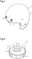
- a helmet 1 includes a spherical shell 2.
- the shell 2 forms an outer shell of the helmet.
- the shell 2 is a semispherical plastic member.
- the material of the shell 2 is selected from, for example, acrylonitrile-butadiene-styrene copolymer (ABS), polycarbonate (PC), and a thermosetting resin impregnated with reinforcement fibers.
- the shell 2 may accommodate, for example, an impact absorption liner that is an interior member for absorbing impacts. Further, the shell 2 may accommodate various types of pads having a lower resilience than the impact absorption liner to, for example, cushion the head.
- the shell 2 includes an open portion 3 to provide a field of view.
- the helmet 1 may include a shield that is a transparent and colorless plate having light-transmissivity. At a closed position, the shield prevents flying foreign objects, rain, and wind from entering the front of the helmet 1 and improves the view of a wearer.
- vents are formed above the open portion 3 to ventilate the inside of the shell 2.
- the vent which connects the inside of the shell 2 and an outer surface of the shell 2, includes a shutter.
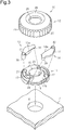
- Each vent is formed by a grommet 10 that is inserted into a through hole 4 of the shell 2.
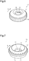
- the grommet 10 includes a base 11, an operation member 12, a first shutter 13, and a second shutter 14.
- the base 11 is coupled to the corresponding through hole 4 of the shell 2.
- the operation member 12 is rotatably coupled to the base 11.
- the first shutter 13 and the second shutter 14 are moved when the operation member 12 is rotated.
- the through hole 4 extends through the shell 2 in a thickness-wise direction. That is, the through hole 4 extends from the outer side of the shell 2 to the inner side of the shell 2.
- the base 11 is coupled to the shell 2 surrounding the through hole 4.
- the base 11 is a circular plate having a larger diameter than the through hole 4 and includes a central portion through which a first opening 16 extends in correspondence with the through hole 4.
- the first opening 16 is a circular through hole having substantially the same size as the through hole 4.
- the base 11 includes a rear surface 11a and a front surface 11b.
- the rear surface 11a is attached to the shell 2.
- the front surface 11b is located at a side opposite to the rear surface 11a and includes the shutters 13 and 14.
- the rear surface 11a includes a fitting wall 17 arranged around the first opening 16.
- the first opening 16 is formed at an inner side of the fitting wall 17, and the fitting wall 17 is fitted into the through hole 4.
- the base 11 includes the fitting wall 17, which is fitted into the through hole 4, and a portion outside the through hole 4.
- the circumferential edge of the rear surface 11a includes rotation guides 18 that guide the rotation of the operation member 12 relative to the base 11 and determines a rotation range of the operation member 12.
- Each rotation guide 18 is a groove having the form of a recess extending in the circumferential direction over the rotation range of the operation member 12, that is, a range in which the first and second shutters 13 and 14 open and close.
- the front surface 11b of the base 11 includes a first main guide groove 21 and a second main guide groove 22.
- the first main guide groove 21 guides movement of the first shutter 13, and the second main guide groove 22 guides movement of the second shutter 14.
- the first and second main guide grooves 21 and 22 are grooves each having the form of a recess and are engaged with first and second main guide protrusions 36 and 37, respectively.
- the first and second main guide protrusions 36 and 37 are arranged on first ends of the first and second shutters 13 and 14, respectively.
- the first and second main guide grooves 21 and 22 each have the shape of an arc extending in the circumferential direction of the first opening 16 at an outer side of the first opening 16.
- the front surface 11b of the base 11 includes a first sub-guide groove 23, which guides movement of the first shutter 13, and a second sub-guide groove 24, which guides movement of the second shutter 14.
- the first and second sub-guide grooves 23 and 24 are engaged with first and second sub-guide protrusions 38 and 39 arranged on second ends of the first and second shutters 13 and 14, respectively.
- the first and second sub-guide grooves 23 and 24 are each configured by a recess extending in a direction that intersects with the first and second main guide grooves 21 and 22. In other words, the first and second main guide grooves 21 and 22 extend in a circumferential direction while the first and second sub-guide grooves 23 and 24 extend in a radial direction.
- the operation member 12 is rotatably arranged relative to the base 11 and covers the base 11. That is, the operation member 12 is a cover that covers the base 11 and is rotated relative to the base 11.
- the operation member 12 includes a circular top plate 26 and a circumferential wall 27 extending along the circumference of the top plate 26.
- the top plate 26 includes a recessed central portion.
- a second opening 28 extends through the center of the central portion in correspondence with the first opening 16. That is, the operation member 12 includes the second opening 28 at a position corresponding to the first opening 16.
- the second opening 28 is a circular hole having the same size as the first opening 16.
- the first and second openings 16 and 28 form the vent that connects the inside and the outside of the helmet 1.
- the operation member 12 is annular.
- the first and second shutters 13 and 14 open and close the first opening 16 in accordance with the rotation of the operation member 12 relative to the base 11 in the circumferential direction.
- the top plate 26 includes an inner surface in which a first cam groove 31 and a second cam groove 32 are arranged in an inner surface of the top plate 26 outward from the second opening 28.
- the first cam groove 31 and the second cam groove 32 extend along a straight line extending through the center of the second opening 28.
- the first cam groove 31 is a recessed groove engaged with a first driven protrusion 41 of the first shutter 13
- the second cam groove 32 is a recessed groove engaged with a second driven protrusion 42 of the second shutter 14.
- the first cam groove 31 and the second cam groove 32 are each formed by an elongated hole so that the operation member 12 is rotatable.
- the outer circumferential surface of the circumferential wall 27 includes ridges and valleys extending in a height direction.
- the ridges and valleys form an operation portion 29 that is operated to rotate the operation member 12 relative to the base 11.
- the operation portion 29 allows the operation member 12 to be smoothly rotated with a user's fingers.
- two engagement portions 33 are formed in the distal end of the circumferential wall 27 for engagement with the rotation guides 18.
- the two engagement portions 33 oppose each other.
- Each engagement portion 33 is an engagement piece projecting from the distal end of the circumferential wall 27 toward the inner side of the circumferential wall 27.
- the engagement of the engagement portions 33 and the grooves of the rotation guides 18 of the base 11 guides the rotation of the operation member 12 and sets the rotation range in which opening and closing actions of the first and second shutters 13 and 14 are allowed.
- the first and second shutters 13 and 14 are elongated and sized so that when the first shutter 13 and the second shutter 14 abut each other, the first shutter 13 and the second shutter 14 cooperate to close the first opening 16 and the second opening 28. Further, the first and second shutters 13 and 14 are shaped to be located outward from the first opening 16 and the second opening 28 when opening the first opening 16 and the second opening 28.
- the first shutter 13 has a side extending straight in the longitudinal direction that defines an abutment portion 13a
- the second shutter 14 has a side extending straight in the longitudinal direction that defines an abutment portion 14a.
- the abutment portion 13a of the first shutter 13 and the abutment portion 14a of the second shutter 14 can abut each other.
- the first and second shutters 13 and 14 include arcuate portions extending in the longitudinal direction at the opposite side of the abutment portions 13a and 14a.
- the first shutter 13 includes the first main guide protrusion 36 at a first end in the longitudinal direction, and the first main guide protrusion 36 is projected toward the base 11 and engaged with the first main guide groove 21.
- the second shutter 14 includes the second main guide protrusion 37 at a first end in the longitudinal direction.
- the second main guide protrusion 37 is projected toward the base 11 and engaged with the second main guide groove 22.
- the first shutter 13 includes the first sub-guide protrusion 38 at a second end in the longitudinal direction.
- the first sub-guide protrusion 38 is projected toward the base 11 and engaged with the first sub-guide groove 23.
- the second shutter 14 includes the second sub-guide protrusion 39 at a second end in the longitudinal direction.
- the second sub-guide protrusion 39 is projected toward the base 11 and engaged with the second sub-guide groove 24.
- the first shutter 13 includes the first driven protrusion 41 projecting toward the operation member 12.
- the first driven protrusion 41 is engaged with the first cam groove 31 at the first end in the longitudinal direction.
- the second shutter 14 includes the second driven protrusion 42 projecting toward the operation member 12.
- the second driven protrusion 42 is engaged with the second cam groove 32 at the first end in the longitudinal direction.
- the first and second shutters 13 and 14 each include the first end and the second end located at a side opposite to the first end.
- the second end is held by the base 11 in a state in which movement relative to the base 11 is restricted in the circumferential direction.
- the first end is held by the base 11 in a state in which movement relative to the base 11 is allowed in the circumferential direction.
- the first end is held by the operation member 12 in a state in which movement relative to the operation member 12 is restricted in the circumferential direction.
- the first and second main guide protrusions 36 and 37, the first and second main guide grooves 21 and 22, the first and second sub-guide protrusions 38 and 39, the first and second sub-guide grooves 23 and 24, the first cam groove 31, the second cam groove 32, and the first and second driven protrusions 41 and 42 configure an open-close mechanism of the first and second shutters 13 and 14.
- the grommet 10 is attached to the shell 2, for example, by fitting the fitting wall 17 of the base 11 into the through hole 4.
- the abutment portions 13a and 14a of the first and second shutters 13 and 14 abut each other over the first and second openings 16 and 28 so that the first and second shutters 13 and 14 close the first opening 16 and the second opening 28.
- the first and second main guide protrusions 36 and 37 of the first and second shutters 13 and 14 are located at first ends of the first and second main guide grooves 21 and 22.
- the first and second sub-guide protrusions 38 and 39 of the first and second shutters 13 and 14 are located at first ends of the first and second sub-guide grooves 23 and 24.
- the first and second openings 16 and 28 are opened to draw outside air into the helmet 1.
- the user holds the operation portion 29 of the operation member 12 and rotates the operation member 12 in a first direction (direction indicated by arrow D in Fig. 2 ).
- the first shutter 13 is moved by the first driven protrusion 41 and the first cam groove 31 in a direction that opens the first and second openings 16 and 28.
- the second shutter 14 is moved by the second driven protrusion 42 and the second cam groove 32 in the direction that opens the first and second openings 16 and 28.
- first and second main guide protrusions 36 and 37 of the first and second shutters 13 and 14 are moved from the first ends to second ends of the first and second main guide grooves 21 and 22, respectively.
- first and second sub-guide protrusions 38 and 39 of the first and second shutters 13 and 14 are moved from the first ends to second ends of the first and second sub-guide grooves 23 and 24, respectively.
- the first and second shutters 13 and 14 are moved away from the first and second openings 16 and 28 and allow the inside of the shell 2 to be ventilated.
- the amount of the first and second openings 16 and 28 are opened is changed in accordance with the amount of the operation member 12 is rotated. That is, the first and second shutters 13 and 14 are moved when the operation member 12 is rotated. This adjusts the amount of air flowing into the shell 2. Further, when closing the first and second openings 16 and 28, the operation member 12 is rotated in a second direction to move the first and second shutters 13 and 14 in a direction that closes the first and second openings 16 and 28.
- the second direction is a direction opposite to the direction indicated by arrow D in Fig. 6 . In this case, the operation member 12 is in a state in which the abutment portions 13a and 14a of the first and second shutters 13 and 14 abut each other over the first and second openings 16 and 28.
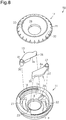
- a grommet 50 of the second embodiment includes the base 11 and the operation member 12 that differ in shape from the base 11 and the operation member 12 of the first embodiment.
- the base 11 includes a bottom plate 11c and a circumferential wall 11d.
- the bottom plate 11c includes the first opening 16, around which the first main guide groove 21, the second main guide groove 22, the first sub-guide groove 23, and the second sub-guide groove 24 are arranged.
- the circumferential wall 11d includes the rotation guides 18 that are slits extending through the circumferential wall 11d in a circumferential direction.
- the operation member 12 includes a recessed central portion.
- the second opening 28 corresponding to the first opening 16 extends through the center of the central portion.
- An inclination surface that is inclined downward extends from the outer side of the recessed central portion. Further, ridges and valleys are formed in the inclination surface in a circumferential direction. This forms the operation portion 29 that is rotated to rotate the operation member 12 relative to the base 11.
- the first and second main guide protrusions 36 and 37 of the first and second shutters 13 and 14 are engaged with the first and second main guide grooves 21 and 22 of the base 11, and the first and second sub-guide protrusions 38 and 39 are engaged with the first and second sub-guide grooves 23 and 24. Further, the first and second driven protrusions 41 and 42 of the first and second shutters 13 and 14 are engaged with the first and second cam grooves 31 and 32 of the operation member 12.
- the grommet 50 also has the same advantages as the grommet 10 of the first embodiment.
- the number of shutters is not limited to two as long as the number is more than one.
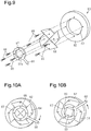
- One example of a grommet 60 in accordance with a third embodiment including four shutters is shown in Figs 9, 10A, and 10B .
- the grommet 60 includes a base 62.
- the base 62 is a circular plate having a larger diameter than the through hole 4 and includes a central portion having a first opening 63 corresponding to the through hole 4.
- the four shutters 64 are pivotally coupled to the base 62 by screws 65. Each of the four shutters 64 is pivotal relative to the base 62 about the corresponding screw 65. The first opening 63 is opened and closed by pivoting the four shutters 64.
- the four shutters 64 are operated and pivoted by an operation member 66.
- the operation member 66 includes an annular portion 67 and a rod-shaped operation portion 68 arranged on the annular portion 67.
- the inner side of the annular portion 67 defines a second opening 67a, and the second opening 67a has a diameter that is equal to, larger than, or smaller than the first opening 63.
- the four shutters 64 are pivotally coupled to the annular portion 67 by screws 69.
- Each of the four shutters 64 is pivotal relative to the annular portion 67 about the corresponding screw 69.
- each shutter 64 is pivoted to open or close the first opening 63.
- the first opening 63 is closed when the operation portion 68 is moved downward, and the first opening 63 is opened when the operation portion 68 is moved upward.
- a square vent is formed.
- the rotation guides 18 and the engagement portions 33 may be omitted. That is, the rotation of the operation member 12 relative to the base 11 may be guided without the rotation guides 18 and the engagement portions 33.
- the circumferential wall of the operation member 12 may be fitted into the inner side of the circumferential wall of the base 11 so as to guide the rotation.
- the circumferential wall of the operation member 12 may be fitted to the outer side of the circumferential wall of the base 11 so as to guide the rotation.
- the rotation of the operation member 12 relative to the base 11 is guided by the engagement portions 33 and the rotation guides 18, and the engagement portions 33 and the rotation guides 18 set the rotation range of the operation member 12 relative to the base 11.
- the rotation of the operation member 12 relative to the base 11 may be guided in a configuration in which the rotation range of the operation member 12 relative to the base 11 is not set.
- the shutter does not have to be completely covered by the operation member 12 (refer to Figs 9, 10A, and 10B ).
- the operation member may be located at a positioned separated from the first opening 16 and does not have to include the second opening 28.
- the shutter may be overlapped with part of the first opening 16 even in a fully open state.
- the first and second main guide protrusions 36 and 37, the first and second sub-guide protrusions 38 and 39, and the first and second driven protrusions 41 and 42 may be arranged at any position.
- center axes of the first and second main guide protrusions 36 and 37 do not have to coincide with center axes of the first and second driven protrusions 41 and 42.
- one set of the first and second main guide protrusions 36 and 37 and the first and second driven protrusions 41 and 42 may be arranged on the first ends of the first and second shutters 13 and 14, and the other set of the first and second main guide protrusions 36 and 37 and the first and second driven protrusions 41 and 42 may be arranged between the first ends and the second ends of the first and second shutters 13 and 14. Further, the first and second sub-guide protrusions 38 and 39 may be arranged between the first ends and the second ends of the first and second shutters 13 and 14 instead of being arranged on the second ends.
- the first and second sub-guide protrusions 38 and 39 may be omitted from the first and second shutters 13 and 14, and the first and second shutters 13 and 14 may include only the first and second main guide protrusions 36 and 37. The movement of the first and second shutters 13 and 14 may be guided only by the first and second main guide protrusions 36 and 37.
- the number of vents formed by the grommet is not limited to two like in Fig. 1 . That is, the number of vents may be one or three or more. A larger number of vents improves ventilation. Further, the helmet may include a vent formed by a different mechanism in addition to the vent formed by the grommet.
- the helmet 1 may include a shield that is a transparent and colorless plate having light-transmissivity. At a closed position, the shield prevents flying foreign objects, rain, and wind from entering the front helmet 1 and improves the field of view of a wearer.
- the helmet may be a helmet for a bicycle or an automobile in addition to a motorcycle.
- a helmet may be used for construction work, light labor, or electric work.
Landscapes
- Helmets And Other Head Coverings (AREA)
Applications Claiming Priority (1)
| Application Number | Priority Date | Filing Date | Title |
|---|---|---|---|
| JP2019102839A JP7265935B2 (ja) | 2019-05-31 | 2019-05-31 | ヘルメットおよびグロメット |
Publications (2)
| Publication Number | Publication Date |
|---|---|
| EP3744201A1 true EP3744201A1 (de) | 2020-12-02 |
| EP3744201B1 EP3744201B1 (de) | 2023-01-25 |
Family
ID=70857080
Family Applications (1)
| Application Number | Title | Priority Date | Filing Date |
|---|---|---|---|
| EP20176527.8A Active EP3744201B1 (de) | 2019-05-31 | 2020-05-26 | Helm und öse |
Country Status (3)
| Country | Link |
|---|---|
| EP (1) | EP3744201B1 (de) |
| JP (1) | JP7265935B2 (de) |
| CN (1) | CN112006371B (de) |
Citations (3)
| Publication number | Priority date | Publication date | Assignee | Title |
|---|---|---|---|---|
| JPH0287027U (de) | 1988-12-22 | 1990-07-10 | ||
| JPH10121317A (ja) | 1996-10-17 | 1998-05-12 | Arai Helmet:Kk | ヘルメットの換気構造 |
| KR20000047448A (ko) * | 1998-12-10 | 2000-07-25 | 홍완기 | 헬멧용 에어벤트 |
Family Cites Families (15)
| Publication number | Priority date | Publication date | Assignee | Title |
|---|---|---|---|---|
| CN1253756A (zh) * | 1998-11-13 | 2000-05-24 | 洪完基 | 用于头盔的护罩连接器 |
| JP2002309430A (ja) * | 2001-04-10 | 2002-10-23 | Takikiyo Kk | ヘルメット用風防開閉金具及び風防付きヘルメット |
| KR100468348B1 (ko) * | 2003-03-24 | 2005-01-27 | 주식회사 홍진에이치제이씨 | 헬멧용 에어벤트 |
| JP4826376B2 (ja) * | 2006-07-24 | 2011-11-30 | 住友電装株式会社 | レバー式コネクタ |
| JP3135177U (ja) * | 2007-06-25 | 2007-09-06 | 株式会社ベスト | 錠前装置 |
| CN101559612B (zh) * | 2009-05-19 | 2011-04-13 | 廖一臣 | 一种组合式刨刀的改进结构 |
| JP3155192U (ja) | 2009-06-17 | 2009-11-12 | 有限会社アクショントゥールズ | 外部音聴取装置を備えた乗車用ヘルメット |
| JP5468469B2 (ja) * | 2010-06-03 | 2014-04-09 | 株式会社Shoei | シールドへの防曇シート取り付け構造 |
| JP6173128B2 (ja) * | 2013-08-28 | 2017-08-02 | 株式会社アライヘルメット | ヘルメットにおけるシールドの支持構造 |
| JP2015157674A (ja) * | 2014-02-24 | 2015-09-03 | 株式会社日立製作所 | エレベータ装置 |
| JP6411904B2 (ja) * | 2015-01-26 | 2018-10-24 | 株式会社Shoei | シールドへの防曇シート取り付け構造 |
| JP2017072739A (ja) * | 2015-10-08 | 2017-04-13 | キヤノン株式会社 | 電子機器 |
| JP6849998B2 (ja) * | 2017-04-17 | 2021-03-31 | 株式会社日本アルファ | 操作装置 |
| CN107891892B (zh) * | 2017-11-30 | 2019-09-27 | 新晃老蔡食品有限责任公司 | 牛肉加工用中转车 |
| CN113080559B (zh) * | 2018-07-30 | 2023-12-22 | 安徽省旌德飞迅安全设备有限公司 | 一种智能调节型安全帽 |
-
2019
- 2019-05-31 JP JP2019102839A patent/JP7265935B2/ja active Active
-
2020
- 2020-05-20 CN CN202010429558.7A patent/CN112006371B/zh active Active
- 2020-05-26 EP EP20176527.8A patent/EP3744201B1/de active Active
Patent Citations (3)
| Publication number | Priority date | Publication date | Assignee | Title |
|---|---|---|---|---|
| JPH0287027U (de) | 1988-12-22 | 1990-07-10 | ||
| JPH10121317A (ja) | 1996-10-17 | 1998-05-12 | Arai Helmet:Kk | ヘルメットの換気構造 |
| KR20000047448A (ko) * | 1998-12-10 | 2000-07-25 | 홍완기 | 헬멧용 에어벤트 |
Also Published As
| Publication number | Publication date |
|---|---|
| CN112006371B (zh) | 2023-01-17 |
| EP3744201B1 (de) | 2023-01-25 |
| JP7265935B2 (ja) | 2023-04-27 |
| CN112006371A (zh) | 2020-12-01 |
| JP2020196968A (ja) | 2020-12-10 |
Similar Documents
| Publication | Publication Date | Title |
|---|---|---|
| US10660392B2 (en) | Helmet | |
| US9994155B2 (en) | Vehicle side-view mirror | |
| KR102312200B1 (ko) | 송풍기 | |
| KR101535039B1 (ko) | 자동차의 에어벤트 | |
| JPWO2010082663A1 (ja) | 保護帽 | |
| CN111156679A (zh) | 出风组件及空调器 | |
| EP3744201B1 (de) | Helm und öse | |
| HK1207802A1 (en) | Shield support structure of helmet | |
| JP5870236B2 (ja) | 換気口 | |
| CN212538049U (zh) | 一种具有前面板空调的中框 | |
| US20040019958A1 (en) | Supporting structure of chin-ventilation shutter for full-face type helmet | |
| KR101156276B1 (ko) | 자동차용 회전식 에어벤트 | |
| HK40032814B (en) | Helmet and grommet | |
| HK40032814A (en) | Helmet and grommet | |
| EP3900563B1 (de) | Schirmvorrichtung und helm | |
| JP5928932B2 (ja) | レジスタ | |
| CN113757142A (zh) | 空气调节器用风扇装置 | |
| JP6842346B2 (ja) | レジスタ | |
| CN213754029U (zh) | 盒体、耳机充电盒以及无线耳机组件 | |
| KR20220026319A (ko) | 헬멧용 선바이저 제어수단 | |
| JP4425077B2 (ja) | カップホルダ | |
| CN223939626U (zh) | 摆风组件及空气调度设备 | |
| CN109151291B (zh) | 摄像头装置和空调室内机 | |
| JP4951236B2 (ja) | 風向調整装置 | |
| KR20190084400A (ko) | 에어컨 |
Legal Events
| Date | Code | Title | Description |
|---|---|---|---|
| PUAI | Public reference made under article 153(3) epc to a published international application that has entered the european phase |
Free format text: ORIGINAL CODE: 0009012 |
|
| STAA | Information on the status of an ep patent application or granted ep patent |
Free format text: STATUS: THE APPLICATION HAS BEEN PUBLISHED |
|
| AK | Designated contracting states |
Kind code of ref document: A1 Designated state(s): AL AT BE BG CH CY CZ DE DK EE ES FI FR GB GR HR HU IE IS IT LI LT LU LV MC MK MT NL NO PL PT RO RS SE SI SK SM TR |
|
| AX | Request for extension of the european patent |
Extension state: BA ME |
|
| STAA | Information on the status of an ep patent application or granted ep patent |
Free format text: STATUS: REQUEST FOR EXAMINATION WAS MADE |
|
| 17P | Request for examination filed |
Effective date: 20201210 |
|
| RBV | Designated contracting states (corrected) |
Designated state(s): AL AT BE BG CH CY CZ DE DK EE ES FI FR GB GR HR HU IE IS IT LI LT LU LV MC MK MT NL NO PL PT RO RS SE SI SK SM TR |
|
| GRAP | Despatch of communication of intention to grant a patent |
Free format text: ORIGINAL CODE: EPIDOSNIGR1 |
|
| STAA | Information on the status of an ep patent application or granted ep patent |
Free format text: STATUS: GRANT OF PATENT IS INTENDED |
|
| INTG | Intention to grant announced |
Effective date: 20220816 |
|
| GRAS | Grant fee paid |
Free format text: ORIGINAL CODE: EPIDOSNIGR3 |
|
| GRAA | (expected) grant |
Free format text: ORIGINAL CODE: 0009210 |
|
| STAA | Information on the status of an ep patent application or granted ep patent |
Free format text: STATUS: THE PATENT HAS BEEN GRANTED |
|
| AK | Designated contracting states |
Kind code of ref document: B1 Designated state(s): AL AT BE BG CH CY CZ DE DK EE ES FI FR GB GR HR HU IE IS IT LI LT LU LV MC MK MT NL NO PL PT RO RS SE SI SK SM TR |
|
| REG | Reference to a national code |
Ref country code: GB Ref legal event code: FG4D |
|
| REG | Reference to a national code |
Ref country code: CH Ref legal event code: EP |
|
| REG | Reference to a national code |
Ref country code: DE Ref legal event code: R096 Ref document number: 602020007772 Country of ref document: DE |
|
| REG | Reference to a national code |
Ref country code: AT Ref legal event code: REF Ref document number: 1545381 Country of ref document: AT Kind code of ref document: T Effective date: 20230215 Ref country code: IE Ref legal event code: FG4D |
|
| REG | Reference to a national code |
Ref country code: LT Ref legal event code: MG9D |
|
| REG | Reference to a national code |
Ref country code: NL Ref legal event code: MP Effective date: 20230125 |
|
| REG | Reference to a national code |
Ref country code: AT Ref legal event code: MK05 Ref document number: 1545381 Country of ref document: AT Kind code of ref document: T Effective date: 20230125 |
|
| P01 | Opt-out of the competence of the unified patent court (upc) registered |
Effective date: 20230522 |
|
| PG25 | Lapsed in a contracting state [announced via postgrant information from national office to epo] |
Ref country code: NL Free format text: LAPSE BECAUSE OF FAILURE TO SUBMIT A TRANSLATION OF THE DESCRIPTION OR TO PAY THE FEE WITHIN THE PRESCRIBED TIME-LIMIT Effective date: 20230125 |
|
| PG25 | Lapsed in a contracting state [announced via postgrant information from national office to epo] |
Ref country code: RS Free format text: LAPSE BECAUSE OF FAILURE TO SUBMIT A TRANSLATION OF THE DESCRIPTION OR TO PAY THE FEE WITHIN THE PRESCRIBED TIME-LIMIT Effective date: 20230125 Ref country code: PT Free format text: LAPSE BECAUSE OF FAILURE TO SUBMIT A TRANSLATION OF THE DESCRIPTION OR TO PAY THE FEE WITHIN THE PRESCRIBED TIME-LIMIT Effective date: 20230525 Ref country code: NO Free format text: LAPSE BECAUSE OF FAILURE TO SUBMIT A TRANSLATION OF THE DESCRIPTION OR TO PAY THE FEE WITHIN THE PRESCRIBED TIME-LIMIT Effective date: 20230425 Ref country code: LV Free format text: LAPSE BECAUSE OF FAILURE TO SUBMIT A TRANSLATION OF THE DESCRIPTION OR TO PAY THE FEE WITHIN THE PRESCRIBED TIME-LIMIT Effective date: 20230125 Ref country code: LT Free format text: LAPSE BECAUSE OF FAILURE TO SUBMIT A TRANSLATION OF THE DESCRIPTION OR TO PAY THE FEE WITHIN THE PRESCRIBED TIME-LIMIT Effective date: 20230125 Ref country code: HR Free format text: LAPSE BECAUSE OF FAILURE TO SUBMIT A TRANSLATION OF THE DESCRIPTION OR TO PAY THE FEE WITHIN THE PRESCRIBED TIME-LIMIT Effective date: 20230125 Ref country code: ES Free format text: LAPSE BECAUSE OF FAILURE TO SUBMIT A TRANSLATION OF THE DESCRIPTION OR TO PAY THE FEE WITHIN THE PRESCRIBED TIME-LIMIT Effective date: 20230125 Ref country code: AT Free format text: LAPSE BECAUSE OF FAILURE TO SUBMIT A TRANSLATION OF THE DESCRIPTION OR TO PAY THE FEE WITHIN THE PRESCRIBED TIME-LIMIT Effective date: 20230125 |
|
| PG25 | Lapsed in a contracting state [announced via postgrant information from national office to epo] |
Ref country code: SE Free format text: LAPSE BECAUSE OF FAILURE TO SUBMIT A TRANSLATION OF THE DESCRIPTION OR TO PAY THE FEE WITHIN THE PRESCRIBED TIME-LIMIT Effective date: 20230125 Ref country code: PL Free format text: LAPSE BECAUSE OF FAILURE TO SUBMIT A TRANSLATION OF THE DESCRIPTION OR TO PAY THE FEE WITHIN THE PRESCRIBED TIME-LIMIT Effective date: 20230125 Ref country code: IS Free format text: LAPSE BECAUSE OF FAILURE TO SUBMIT A TRANSLATION OF THE DESCRIPTION OR TO PAY THE FEE WITHIN THE PRESCRIBED TIME-LIMIT Effective date: 20230525 Ref country code: GR Free format text: LAPSE BECAUSE OF FAILURE TO SUBMIT A TRANSLATION OF THE DESCRIPTION OR TO PAY THE FEE WITHIN THE PRESCRIBED TIME-LIMIT Effective date: 20230426 Ref country code: FI Free format text: LAPSE BECAUSE OF FAILURE TO SUBMIT A TRANSLATION OF THE DESCRIPTION OR TO PAY THE FEE WITHIN THE PRESCRIBED TIME-LIMIT Effective date: 20230125 |
|
| REG | Reference to a national code |
Ref country code: DE Ref legal event code: R097 Ref document number: 602020007772 Country of ref document: DE |
|
| PG25 | Lapsed in a contracting state [announced via postgrant information from national office to epo] |
Ref country code: SM Free format text: LAPSE BECAUSE OF FAILURE TO SUBMIT A TRANSLATION OF THE DESCRIPTION OR TO PAY THE FEE WITHIN THE PRESCRIBED TIME-LIMIT Effective date: 20230125 Ref country code: RO Free format text: LAPSE BECAUSE OF FAILURE TO SUBMIT A TRANSLATION OF THE DESCRIPTION OR TO PAY THE FEE WITHIN THE PRESCRIBED TIME-LIMIT Effective date: 20230125 Ref country code: EE Free format text: LAPSE BECAUSE OF FAILURE TO SUBMIT A TRANSLATION OF THE DESCRIPTION OR TO PAY THE FEE WITHIN THE PRESCRIBED TIME-LIMIT Effective date: 20230125 Ref country code: DK Free format text: LAPSE BECAUSE OF FAILURE TO SUBMIT A TRANSLATION OF THE DESCRIPTION OR TO PAY THE FEE WITHIN THE PRESCRIBED TIME-LIMIT Effective date: 20230125 Ref country code: CZ Free format text: LAPSE BECAUSE OF FAILURE TO SUBMIT A TRANSLATION OF THE DESCRIPTION OR TO PAY THE FEE WITHIN THE PRESCRIBED TIME-LIMIT Effective date: 20230125 |
|
| PG25 | Lapsed in a contracting state [announced via postgrant information from national office to epo] |
Ref country code: SK Free format text: LAPSE BECAUSE OF FAILURE TO SUBMIT A TRANSLATION OF THE DESCRIPTION OR TO PAY THE FEE WITHIN THE PRESCRIBED TIME-LIMIT Effective date: 20230125 |
|
| PLBE | No opposition filed within time limit |
Free format text: ORIGINAL CODE: 0009261 |
|
| STAA | Information on the status of an ep patent application or granted ep patent |
Free format text: STATUS: NO OPPOSITION FILED WITHIN TIME LIMIT |
|
| REG | Reference to a national code |
Ref country code: CH Ref legal event code: PL |
|
| 26N | No opposition filed |
Effective date: 20231026 |
|
| PG25 | Lapsed in a contracting state [announced via postgrant information from national office to epo] |
Ref country code: MC Free format text: LAPSE BECAUSE OF FAILURE TO SUBMIT A TRANSLATION OF THE DESCRIPTION OR TO PAY THE FEE WITHIN THE PRESCRIBED TIME-LIMIT Effective date: 20230125 |
|
| REG | Reference to a national code |
Ref country code: BE Ref legal event code: MM Effective date: 20230531 |
|
| PG25 | Lapsed in a contracting state [announced via postgrant information from national office to epo] |
Ref country code: SI Free format text: LAPSE BECAUSE OF FAILURE TO SUBMIT A TRANSLATION OF THE DESCRIPTION OR TO PAY THE FEE WITHIN THE PRESCRIBED TIME-LIMIT Effective date: 20230125 Ref country code: MC Free format text: LAPSE BECAUSE OF FAILURE TO SUBMIT A TRANSLATION OF THE DESCRIPTION OR TO PAY THE FEE WITHIN THE PRESCRIBED TIME-LIMIT Effective date: 20230125 Ref country code: LU Free format text: LAPSE BECAUSE OF NON-PAYMENT OF DUE FEES Effective date: 20230526 Ref country code: LI Free format text: LAPSE BECAUSE OF NON-PAYMENT OF DUE FEES Effective date: 20230531 Ref country code: CH Free format text: LAPSE BECAUSE OF NON-PAYMENT OF DUE FEES Effective date: 20230531 |
|
| REG | Reference to a national code |
Ref country code: IE Ref legal event code: MM4A |
|
| PG25 | Lapsed in a contracting state [announced via postgrant information from national office to epo] |
Ref country code: IE Free format text: LAPSE BECAUSE OF NON-PAYMENT OF DUE FEES Effective date: 20230526 |
|
| PG25 | Lapsed in a contracting state [announced via postgrant information from national office to epo] |
Ref country code: IE Free format text: LAPSE BECAUSE OF NON-PAYMENT OF DUE FEES Effective date: 20230526 |
|
| PG25 | Lapsed in a contracting state [announced via postgrant information from national office to epo] |
Ref country code: BE Free format text: LAPSE BECAUSE OF NON-PAYMENT OF DUE FEES Effective date: 20230531 |
|
| PG25 | Lapsed in a contracting state [announced via postgrant information from national office to epo] |
Ref country code: BG Free format text: LAPSE BECAUSE OF FAILURE TO SUBMIT A TRANSLATION OF THE DESCRIPTION OR TO PAY THE FEE WITHIN THE PRESCRIBED TIME-LIMIT Effective date: 20230125 |
|
| PG25 | Lapsed in a contracting state [announced via postgrant information from national office to epo] |
Ref country code: BG Free format text: LAPSE BECAUSE OF FAILURE TO SUBMIT A TRANSLATION OF THE DESCRIPTION OR TO PAY THE FEE WITHIN THE PRESCRIBED TIME-LIMIT Effective date: 20230125 |
|
| PGFP | Annual fee paid to national office [announced via postgrant information from national office to epo] |
Ref country code: DE Payment date: 20250519 Year of fee payment: 6 |
|
| PGFP | Annual fee paid to national office [announced via postgrant information from national office to epo] |
Ref country code: IT Payment date: 20250530 Year of fee payment: 6 |
|
| PGFP | Annual fee paid to national office [announced via postgrant information from national office to epo] |
Ref country code: FR Payment date: 20250521 Year of fee payment: 6 |
|
| PG25 | Lapsed in a contracting state [announced via postgrant information from national office to epo] |
Ref country code: CY Free format text: LAPSE BECAUSE OF FAILURE TO SUBMIT A TRANSLATION OF THE DESCRIPTION OR TO PAY THE FEE WITHIN THE PRESCRIBED TIME-LIMIT; INVALID AB INITIO Effective date: 20200526 |
|
| PG25 | Lapsed in a contracting state [announced via postgrant information from national office to epo] |
Ref country code: HU Free format text: LAPSE BECAUSE OF FAILURE TO SUBMIT A TRANSLATION OF THE DESCRIPTION OR TO PAY THE FEE WITHIN THE PRESCRIBED TIME-LIMIT; INVALID AB INITIO Effective date: 20200526 |
|
| PG25 | Lapsed in a contracting state [announced via postgrant information from national office to epo] |
Ref country code: TR Free format text: LAPSE BECAUSE OF FAILURE TO SUBMIT A TRANSLATION OF THE DESCRIPTION OR TO PAY THE FEE WITHIN THE PRESCRIBED TIME-LIMIT Effective date: 20230125 |
|
| PGFP | Annual fee paid to national office [announced via postgrant information from national office to epo] |
Ref country code: GB Payment date: 20260324 Year of fee payment: 7 |