EP3744209B1 - Elastisches armband mit gliedern - Google Patents
Elastisches armband mit gliedern Download PDFInfo
- Publication number
- EP3744209B1 EP3744209B1 EP19177095.7A EP19177095A EP3744209B1 EP 3744209 B1 EP3744209 B1 EP 3744209B1 EP 19177095 A EP19177095 A EP 19177095A EP 3744209 B1 EP3744209 B1 EP 3744209B1
- Authority
- EP
- European Patent Office
- Prior art keywords
- links
- bracelet
- rods
- passages
- elastic
- Prior art date
- Legal status (The legal status is an assumption and is not a legal conclusion. Google has not performed a legal analysis and makes no representation as to the accuracy of the status listed.)
- Active
Links
Images



Classifications
-
- A—HUMAN NECESSITIES
- A44—HABERDASHERY; JEWELLERY
- A44C—PERSONAL ADORNMENTS, e.g. JEWELLERY; COINS
- A44C5/00—Bracelets; Wrist-watch straps; Fastenings for bracelets or wrist-watch straps
- A44C5/0053—Flexible straps
- A44C5/0069—Flexible straps extensible
-
- A—HUMAN NECESSITIES
- A44—HABERDASHERY; JEWELLERY
- A44C—PERSONAL ADORNMENTS, e.g. JEWELLERY; COINS
- A44C5/00—Bracelets; Wrist-watch straps; Fastenings for bracelets or wrist-watch straps
- A44C5/02—Link constructions
- A44C5/04—Link constructions extensible
- A44C5/08—Link constructions extensible having separate links
Definitions
- the present invention relates to an elastic link bracelet, in particular for a watch, comprising two rows of lateral links, each link of a row of lateral links being connected to a link of the other row of lateral links by two rods arranged perpendicular to the longitudinal direction of the bracelet, and comprising at least one row of central links each articulated on two rods connected to different lateral links, the central links each comprising a tubular envelope which is oriented parallel to the rods and which is closed on at least one side by an insert in which has been arranged at least one passage arranged to allow the two rods on which the central link is articulated to pass through the insert, at least one of the two rods on which the central link is articulated being further stressed, in direction of the other rod, by at least one elastic element housed in the tubular casing.
- the patent document CH 648 818 in particular describes an elastic link bracelet conforming to the above definition and each central link of which has a central housing passing right through the link perpendicular to the longitudinal direction of the bracelet.
- the housing is partially closed on one side by a wall pierced with a first longitudinal slot, and an insert pierced with a second longitudinal slot is provided to allow the other side of the housing to be partially closed as well.
- Two screws which are connected to pairs of different side links enter the central housing through the first longitudinal slot, and exit through the second slot, so that they pass right through the central link.
- Two compression springs are still arranged inside the housing central. These springs are arranged parallel to the longitudinal direction of the bracelet, in the extension of one another.
- the two screws which pass through the central link are inserted so that the springs are respectively compressed between the two ends of the central housing, on the one hand, and the two screws, on the other hand.
- the two screws on which the central link is articulated have the possibility of shifting transversely (parallel to the longitudinal direction of the bracelet) so as to deviate more or less l 'against each other against the two compression springs. It will be understood that this last characteristic allows this known bracelet to lengthen under the effect of a tensile force.
- the elastic link bracelet of the prior art which has just been described has certain defects. Indeed, the two screws on which a central link is articulated penetrate and emerge on either side of the central housing by borrowing the same two longitudinal slots. Thus, the only terminal limiting the transverse offset of a screw along the longitudinal slots is the presence of the other screw which is itself urged in the other direction by the spring associated with it. The two screws can therefore in theory abut one against the other at mid-length of the longitudinal slots. One might think that the presence of the lateral links of the bracelet would make it possible to prevent such approximation of the screws.
- An aim of the present invention is to remedy the drawbacks of the prior art which have just been explained.
- the present invention achieves this and other object by providing an elastic link bracelet according to the appended claim 1.
- the inserts which close at least one side of each central link have two passages arranged so as to each receive one of the two rods which pass through the insert. At least one of the two passages is dimensioned so as to receive and guide the rod with a certain clearance oriented parallel to the longitudinal direction of the bracelet.
- the two passages are separated from one another by an in-between delimited by two bearing surfaces oriented back to back. It will be understood that the two bearing surfaces of an insert play the role of stops making it possible to maintain the two rods, on which a central link is articulated, away from each other. Thanks to this characteristic, an elastic link bracelet according to the invention has the same appearance as an ordinary bracelet when it is not worn.
- the elastic elements which are housed in the tubular envelopes of the central links are prestressed, so that the force with which they recall at least one of the two rods on which the central links are articulated against the surface of corresponding support is equal to at least half of the total weight of the bracelet, including the weight of any accessory attached to the strap (for example, in the case of a watch strap, the weight of the wristwatch as a whole). It will be understood that due to this characteristic, a tensile force exerted on the bracelet must exceed the force with which the elastic members are preloaded before the bracelet begins to elongate.
- the tensile force exerted by gravity on the links of the bracelet, when it is suspended by its clasp is equal to half of the total weight of the bracelet. It will therefore be understood that the fact that the springs are preloaded allows the bracelet to retain its minimum length when it is suspended by its clasp.
- the bracelet of the invention is always adjusted in a manner that is both aesthetic and comfortable.
- the figure 1 is an exploded perspective view of a portion of an elastic metal link bracelet which conforms to an exemplary embodiment of the invention.
- the strap of the present example is a watch strap. It can be seen that this bracelet comprises two rows of lateral links (respectively referenced 4a and 4b), and that each link 4a of a row of lateral links is designed to be connected to a link 4b of the other row of lateral links by two rods or pins (referenced 3) arranged perpendicular to the longitudinal direction of the bracelet.
- the bracelet also comprises a row of central links each articulated on two pins connected to different lateral links 4a, 4b.
- the central links comprise a tubular envelope 1 oriented perpendicular to the longitudinal direction of the bracelet.
- these tubular envelopes are made of metal, preferably of precious metal. Note that it is possible to make envelopes 1 of relatively easy way. They can for example be obtained by extrusion and then cut to the desired length and polished.
- each central link of the bracelet contains a compartment 5 which is arranged in the middle part of the tubular casing 1 between the two inserts 2a and 2b (a single compartment 5 is shown in the figure 1 inside the third central link which is shown in cutaway).
- the two inserts occupy approximately 60% of the empty space inside the tubular casing 1, and the compartment 5 occupy the remaining 40%.
- the inserts 2a, 2b each have two passages 11 which are arranged in the extension of the two passages of the other insert, so as to allow the two rods 3 which are inserted in a central link to pass through the two inserts.
- the ends of the pins 3 have longitudinal ridges which are designed to be forced out into blind holes in the lateral links 4a, 4b. It will be noted that two pins 3 which pass through the same central link are each driven by force into two lateral links 4a and two different lateral links 4b, so as to form the chain of the bracelet.
- the ends of the rods could be made integral with the side links in another way. The rods could for example be welded or glued, or else be threaded and screwed into threaded holes of the side links.
- the figures 2A and 2B are two partial cross-sectional views, respectively vertical and horizontal, which show the same assembly consisting of a central link, two pins 3a, 3b and two side links 4a, 4b of the bracelet of the figure 1 ; the central link being articulated on one of the two pins (referenced 3a), and the two pins each being fixed by their two ends to the two lateral links 4a, 4b.
- the central link is formed of a tubular envelope 1 and two inserts 2a and 2b.
- the two passages 11 provided in each of the inserts 2a, 2b consist of two profiled and through holes which are parallel to one another.
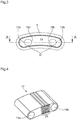
- the figure 3 further shows that the cross-sectional profile of the two passages is oblong-shaped. It can also be seen that the two oblongs are turned so that their longitudinal axis coincides with a horizontal axis AA which connects the centers of the two pins 3 which pass through the inserts 2a, 2b ( figure 2A and 3 ).
- the insert 2a comprises two bearing surfaces 15a, 15b arranged between the passages 11 and oriented back to back.
- the two bearing surfaces are provided as stops for the two pins which pass through the inserts 2a, 2b (only one of these pins (referenced 3a) being shown in the figures 2A and 2B ).
- the presence of the two bearing surfaces 15 makes it possible to maintain the two pins 3 which pass through the same central link at least a minimum distance from each other.
- the bearing surfaces 15 are each formed by the portion of the edge of a passage 11 which is closest to the other passage 11.
- each pin thus has the possibility of pivoting. axially on itself inside the central link which it passes through, so that the assembly formed by the pin and the two passages 11 which it passes through to enter and to emerge from a central link, constitutes a kind hinge arranged to fulfill a function of articulation between a central link and a pair of lateral links 2a, 2b of the bracelet.
- the pins 3 due to the oblong shape of the profile of each passage 11, the pins 3 also have the possibility of ripping with greasy friction, inside the passages, in the longitudinal direction of the bracelet.
- this characteristic gives the possibility of varying the distance separating the two pins 3 between a minimum distance which corresponds to a situation where the two pins are respectively in abutment against the bearing surfaces 15a and 15b, and a maximum distance which corresponds to a contrary situation (not shown), where the two pins abut respectively against the parts (respectively referenced 13a and 13b) of the walls of the two passages 11 which are located opposite the bearing surfaces 15a, 15b.
- the difference between the minimum value and the maximum value of the distance between the two pins 3 could be about 0.6mm.
- each pin 3 has the possibility of ripping transversely over a distance of 0.3mm inside the passage 11 in which it is inserted.
- the two passages 11 which pass through an insert (2a or 2b) have the same dimensions and the same profile. It will be understood, however, that, in accordance with other embodiments of the invention, the profiles of the two passages could be different.
- the passages could be shaped so that only one of the two pins has the possibility of ripping parallel to the longitudinal axis of the bracelet. The other pin would then be inserted into a passage having a circular profile and the diameter of which would be adjusted to that of the pin. This second pin would therefore have the possibility of pivoting axially on itself, but would not have the possibility of ripping transversely.
- each of the two pins 3 on which a central link is articulated is biased, by an elastic element, against one of the two bearing surfaces 15a, 15b of the insert which closes one side of the tubular casing 1 of said central link.
- each of the two sides of the tubular casing is closed by insert, and each central link of the bracelet contains a compartment 5 which is arranged in the middle part of the tubular casing 1 between the two inserts 2a, 2b .
- the compartment 5 is designed to serve as a housing for at least one elastic element arranged to urge at least one of the two pins 3, in the direction of the other pin.
- the figure 4 is a perspective view of a tension spring 17, which constitutes a first variant of said at least one elastic element adapted to be housed in the tubular casing 1 of each of the central links of the bracelet.
- the general external shape of the tension spring 17 is that of a rectangular parallelepiped, the dimensions of which are chosen so as to allow it to be housed in the compartment 5 inside a central link.
- the spring 17 illustrated is a tension spring and its two ends are arranged to be hooked to the two pins 3 which pass through the central link. To this end, the ends of the spring 17 each comprise a cylindrical passage (respectively referenced 19a and 19b) in which is inserted one of the two pins 3.
- the cylindrical passages 19a and 19b are oriented parallel to the two pins. large faces (the lower face and the upper face of the rectangular parallelepiped formed by the spring), and also oriented parallel to the two small faces (the two opposite ends of the rectangular parallelepiped).
- the tension spring 17 comprises an elastic part 21, in the form of rectangular coil, which is interposed between the two cylindrical passages 19a, 19b.
- the spring 17 and its coil can for example be made from a section of rectangular profile.
- the elastic element of the invention could not be constituted by a spring, or even by several springs.
- the elastic element could be constituted by an elastomeric tape in the form of a loop (in other words an “elastic”), the loop of which would be arranged to elastically link the two pins. which cross a central link.
- FIGS. 2A and 2B show in particular that the width of the spring 17 is adapted to that of the compartment 5 so that the tension spring occupies substantially the entire width available between the two inserts 2a, 2b.
- the compartment 5 is appreciably longer than the spring 17, so that the spring is free to lengthen when the two pins 3 to which it is attached move away from one another.
- the non-cylindrical shape of the passages 11 gives the possibility for the two pins 3 to move apart by approximately 0.6mm when they pass from the situation illustrated, in which they abut against the bearing surfaces 15a.
- the tension spring 17 is prestressed. In other words, it is dimensioned so that, in the absence of constraints, its length is appreciably less than the minimum distance which separates the pins 3 hooked to both ends of the spring.
- the spring 17 is sufficiently pre-stressed to return the two pins 3 against the bearing surfaces 15 with a force at least equal to half the total weight of the wristwatch.
- the tensile force exerted by gravity on the links of a bracelet, when it is suspended by its clasp is equal to half of the total weight of the wristwatch. For example, a wristwatch with a total mass of 123 grams is pulled down with a force of 1.2 Newton, and the force to which each central link is subjected is 0.6 Newton.
- the two rods 3 which pass through a central link are biased against the bearing surfaces 15 with a force at least equal to half the total weight of the bracelet, the latter can be worn stretched around the wrist.
- the preload of the springs 17 defines a triggering threshold for the extension of the springs. It is only when the bracelet is subjected to a tensile force which exceeds this threshold value, that the pins which pass through the same central link move away from one another, and thus cause the bracelet to lengthen.
- the figure 5 is a perspective view of a double compression spring 67 which constitutes a second variant of said at least one elastic element adapted to be housed in the tubular casing 1 of each of the central links of the bracelet which is the subject of this present description.
- the figure 6 is a vertical sectional view illustrating the arrangement of the spring 67 inside the tubular casing 1 of one of the central links of the bracelet.
- the spring 67 is formed from a single rectangular flexible sheet, two opposite ends of which have been plastically deformed so as to return them each by about 270 ° on itself. As shown in the figure 6 , the two curved ends of the spring 67 are adapted to serve as contact surfaces (referenced 69a and 69b) for the two pins 3 on which the central link is articulated. The figure also shows that the spring 67 is dimensioned so as to adjust, over almost its entire length, to the contours of the rigid inner wall of the tubular casing 1. Only the ends constituting the two contact surfaces 69a, 69b of the spring emerge from the inner wall, and it will be understood that these ends are the only parts of the spring which have the possibility to flex elastically in the event of stress.
- the length of the spring 67 does not change when it is subjected to a stress, but its two curved ends each have the possibility of deforming elastically when they are pushed back by a pin 3 in the direction of a portion of the wall of the cylindrical element 1 against which the curved end in question rests.
- the two curved ends of the spring 67 behave like two compression springs each arranged so as to urge one of the pins 3 in the direction of the corresponding bearing surface 15a, 15b. This is the reason why the spring 67 is referred to as a "double compression spring".
Landscapes
- Adornments (AREA)
Claims (10)
- Elastisches Gliederarmband mit zwei Reihen seitlicher Glieder (4a, 4b), wobei jedes Glied einer Reihe seitlicher Glieder mit einem Glied der anderen Reihe seitlicher Glieder durch zwei rechtwinklig zur Längsrichtung des Armbandes angeordnete Stifte (3) verbunden ist, und mit mindestens einer Reihe mittlerer Glieder, die jeweils an zwei mit verschiedenen seitlichen Gliedern (4a, 4b) verbundenen Stiften (3) angelenkt sind, wobei die zentralen Glieder jeweils eine tubuläre Ummantelung (1) umfassen, die parallel zu den Stiften ausgerichtet ist und die auf mindestens einer Seite durch einen Einsatz (2a, 2b) verschlossen ist, wobei mindestens ein Durchgang (11) in dem Einsatz so angeordnet ist, dass die beiden Stifte (3), an denen das zentrale Glied angelenkt ist, den Einsatz durchragen können, wobei ferner mindestens einer der beiden Stifte (3), an dem das zentrale Verbindungsglied angelenkt ist, durch mindestens ein in der tubulären Ummantelung (1) aufgenommenes elastisches Element (17) in Richtung des anderen Stifts vorgespannt ist; dadurch gekennzeichnet, dass der Einsatz (2a, 2b) zwei Durchgänge (11) aufweist, die dazu eingerichtet sind, jeweils einen der beiden Stifte (3), an denen das zentrale Glied angelenkt ist, aufzunehmen und zu führen, wobei mindestens einer der beiden Durchgänge so dimensioniert ist, dass er den genannten Stift mit einem gewissen Spiel in Längsrichtung des Armbands aufnimmt und führt, wobei die beiden Durchgänge (11) durch einen Zwischenraum voneinander getrennt sind, der zwei Rücken an Rücken ausgerichtete Anlageflächen (15) aufweist, die dazu eingerichtet sind, als Widerlager für die beiden den Einsatz (2a, 2b) durchragenden Stifte (3) zu dienen, um diese voneinander beabstandet zu halten, und dass das mindestens eine elastische Element (17) so vorgespannt ist, dass mindestens einer der beiden den Einsatz (2a, 2b) durchragenden Stifte (3) mit einer Kraft gegen eine der beiden Anlageflächen (15) zurückgezogen wird, die mindestens der Hälfte des Gesamtgewichts des Armbands entspricht.
- Elastisches Gliederarmband nach Anspruch 1, dadurch gekennzeichnet, dass die mittleren Glieder jeweils zwei Einsätze (2a, 2b) aufweisen, welche die tubuläre Ummantelung (1) beidseitig verschließen, wobei die beiden Einsätze jeweils zwei Durchgänge (11) aufweisen, die in Verlängerung der beiden Durchgänge des jeweils anderen Einsatzes angeordnet sind.
- Elastisches Gliederarmband nach Anspruch 2, dadurch gekennzeichnet, dass das mindestens eine elastische Element (17) in einem Abschnitt (5) aufgenommen ist, der im mittleren Teil der tubulären Ummantelung (1) zwischen den beiden Einsätzen (2a, 2b) angeordnet ist.
- Elastisches Gliederarmband nach einem der Ansprüche 1, 2 und 3, dadurch gekennzeichnet, dass die beiden Durchgänge (11), die der mindestens eine Einsatz (2a, 2b) aufweist, parallel zueinander angeordnete Durchgangslöcher sind, und dass das Querschnittsprofil mindestens eines der Durchgangslöcher länglich ist.
- Elastisches Gliederarmband nach Anspruch 4, dadurch gekennzeichnet, dass die beiden Durchgänge (11) das gleiche längliche Profil aufweisen und dass die Durchgänge (11) so ausgerichtet sind, dass die Hauptachsen ihrer jeweiligen länglichen Profile in der gleichen Ebene liegen, wobei diese Ebene auch die beiden Stifte (3) enthält, an denen das zentrale Glied angelenkt ist.
- Elastisches Gliederarmband nach einem der vorangehenden Ansprüche, dadurch gekennzeichnet, dass die Breite der länglichen Durchgänge (11) und der Außendurchmesser der Stifte (3) so beschaffen sind, dass sie ein Gleiten der Stifte in den Durchgängen mit Fettreibung in Längsrichtung des Armbandes ermöglichen, um den Abstand zwischen den beiden Stiften (3), an denen ein zentrales Glied angelenkt ist, zu variieren, wobei mindestens einer der beiden Durchgänge so dimensioniert ist, dass er den Stift mit einem gewissen Spiel in Längsrichtung des Armbandes aufnimmt und führt.
- Elastisches Gliederarmband nach einem der vorangehenden Ansprüche, dadurch gekennzeichnet, dass der Abschnitt (5) lediglich ein elastisches Element (17) enthält, das aus einer Zugfeder oder einem schlaufenförmigen Elastomerband besteht, wobei sich das einzige elastische Element (17) zwischen den beiden Stiften (3), an denen das zentrale Glied angelenkt ist, erstreckt und an letzteren befestigt ist.
- Elastisches Gliederarmband nach Anspruch 7, dadurch gekennzeichnet, dass die Zugfeder (17) als Metallplatte mit einem rechteckigen wendeiförmigen Abschnitt (21) ausgebildet ist.
- Elastisches Gliederarmband nach einem der vorangehenden Ansprüche, dadurch gekennzeichnet, dass es das Armband einer Armbanduhr ist.
- Elastisches Gliederarmband nach Anspruch 9, dadurch gekennzeichnet, dass das mindestens eine elastische Element (17) ausreichend vorgespannt ist, so dass der mindestens eine Stift (3) gegen eine der beiden Anlageflächen (15) mit einer Kraft vorgespannt ist, die mindestens der Hälfte des Gesamtgewichts der Armbanduhr entspricht.
Priority Applications (1)
| Application Number | Priority Date | Filing Date | Title |
|---|---|---|---|
| EP19177095.7A EP3744209B1 (de) | 2019-05-28 | 2019-05-28 | Elastisches armband mit gliedern |
Applications Claiming Priority (1)
| Application Number | Priority Date | Filing Date | Title |
|---|---|---|---|
| EP19177095.7A EP3744209B1 (de) | 2019-05-28 | 2019-05-28 | Elastisches armband mit gliedern |
Publications (2)
| Publication Number | Publication Date |
|---|---|
| EP3744209A1 EP3744209A1 (de) | 2020-12-02 |
| EP3744209B1 true EP3744209B1 (de) | 2021-10-13 |
Family
ID=66676265
Family Applications (1)
| Application Number | Title | Priority Date | Filing Date |
|---|---|---|---|
| EP19177095.7A Active EP3744209B1 (de) | 2019-05-28 | 2019-05-28 | Elastisches armband mit gliedern |
Country Status (1)
| Country | Link |
|---|---|
| EP (1) | EP3744209B1 (de) |
Families Citing this family (2)
| Publication number | Priority date | Publication date | Assignee | Title |
|---|---|---|---|---|
| EP4154752B1 (de) | 2021-09-24 | 2025-04-30 | Roventa-Henex SA | Erweiterbare komfortlasche |
| EP4298949B1 (de) * | 2022-06-30 | 2025-02-26 | Comadur SA | Armband mit kettengliedern aus hartem material |
Family Cites Families (3)
| Publication number | Priority date | Publication date | Assignee | Title |
|---|---|---|---|---|
| GB349530A (en) * | 1929-05-02 | 1931-05-21 | Emrich G M B H I | An improved expanding bracelet |
| US2591778A (en) * | 1949-01-18 | 1952-04-08 | Frederich L Brecht | Expansible bracelet |
| DE3040632A1 (de) | 1980-10-29 | 1982-05-27 | Merck Patent Gmbh, 6100 Darmstadt | Cyclohexylphenylderivate, diese enthaltende dielektrika und elektrooptisches anzeigeelement |
-
2019
- 2019-05-28 EP EP19177095.7A patent/EP3744209B1/de active Active
Also Published As
| Publication number | Publication date |
|---|---|
| EP3744209A1 (de) | 2020-12-02 |
Similar Documents
| Publication | Publication Date | Title |
|---|---|---|
| EP2709482B1 (de) | Armband für uhren | |
| EP0834099B1 (de) | Brillengestell mit elastischem scharnier | |
| EP0807844B1 (de) | Abnehmbares Federscharnier für Brille | |
| EP1190642B1 (de) | Rucksack mit einem Winkeldämpfer zwischen der Rückseite des Rucksackes und Schultergurten- und/oder Gürteleinheit | |
| EP1566110A1 (de) | Armband aus starren Gliedern auf einer flexiblen Seele | |
| EP1646297B1 (de) | Bandförmiges verbindungsteil, insbesondere uhrarmband, das durch abschneiden gekürzt werden kann | |
| EP0661938B1 (de) | Faltverschluss für armbänder | |
| EP3744209A1 (de) | Elastisches armband mit gliedern | |
| FR2515510A1 (fr) | Element de massage pour dispositif de massage mecanique | |
| WO2005016066A1 (fr) | Sac a dos avec une sangle abdominale a pivotement angulaire | |
| EP1731053B1 (de) | Nichtausdehnbares Gliedarmband | |
| EP3941300B1 (de) | Schnalle für ein uhrenband oder armband | |
| CH690520A5 (fr) | Dispositif de store mobile pour pièce d'horlogerie. | |
| EP1925227A1 (de) | Faltverschluss für Armbänder | |
| EP1047982A1 (de) | Uhrengehäuse | |
| FR2619292A1 (fr) | Fermoir pour bracelet | |
| EP4154752B1 (de) | Erweiterbare komfortlasche | |
| EP1646792A1 (de) | Profilleiste zur befestigung eines gespannten tuchs | |
| CH718994A2 (fr) | Maillon confort extensible. | |
| WO2012100833A1 (fr) | Bracelet a maillons et son procede d'assemblage | |
| WO2023170128A1 (fr) | Fermoir a boucle deployante | |
| FR2569957A1 (fr) | Ensemble destine a etre porte au poignet | |
| CH719481B1 (fr) | Fermoir à boucle déployante | |
| FR2915508A1 (fr) | Agencement occultant comprenant une barre de guidage | |
| EP2547840A1 (de) | Abdeckvorrichtung |
Legal Events
| Date | Code | Title | Description |
|---|---|---|---|
| PUAI | Public reference made under article 153(3) epc to a published international application that has entered the european phase |
Free format text: ORIGINAL CODE: 0009012 |
|
| STAA | Information on the status of an ep patent application or granted ep patent |
Free format text: STATUS: THE APPLICATION HAS BEEN PUBLISHED |
|
| AK | Designated contracting states |
Kind code of ref document: A1 Designated state(s): AL AT BE BG CH CY CZ DE DK EE ES FI FR GB GR HR HU IE IS IT LI LT LU LV MC MK MT NL NO PL PT RO RS SE SI SK SM TR |
|
| AX | Request for extension of the european patent |
Extension state: BA ME |
|
| STAA | Information on the status of an ep patent application or granted ep patent |
Free format text: STATUS: REQUEST FOR EXAMINATION WAS MADE |
|
| 17P | Request for examination filed |
Effective date: 20210125 |
|
| RBV | Designated contracting states (corrected) |
Designated state(s): AL AT BE BG CH CY CZ DE DK EE ES FI FR GB GR HR HU IE IS IT LI LT LU LV MC MK MT NL NO PL PT RO RS SE SI SK SM TR |
|
| GRAP | Despatch of communication of intention to grant a patent |
Free format text: ORIGINAL CODE: EPIDOSNIGR1 |
|
| STAA | Information on the status of an ep patent application or granted ep patent |
Free format text: STATUS: GRANT OF PATENT IS INTENDED |
|
| RIC1 | Information provided on ipc code assigned before grant |
Ipc: A44C 5/00 20060101AFI20210528BHEP Ipc: A44C 5/08 20060101ALI20210528BHEP |
|
| INTG | Intention to grant announced |
Effective date: 20210614 |
|
| GRAS | Grant fee paid |
Free format text: ORIGINAL CODE: EPIDOSNIGR3 |
|
| GRAA | (expected) grant |
Free format text: ORIGINAL CODE: 0009210 |
|
| STAA | Information on the status of an ep patent application or granted ep patent |
Free format text: STATUS: THE PATENT HAS BEEN GRANTED |
|
| AK | Designated contracting states |
Kind code of ref document: B1 Designated state(s): AL AT BE BG CH CY CZ DE DK EE ES FI FR GB GR HR HU IE IS IT LI LT LU LV MC MK MT NL NO PL PT RO RS SE SI SK SM TR |
|
| REG | Reference to a national code |
Ref country code: GB Ref legal event code: FG4D Free format text: NOT ENGLISH |
|
| REG | Reference to a national code |
Ref country code: CH Ref legal event code: EP |
|
| REG | Reference to a national code |
Ref country code: DE Ref legal event code: R096 Ref document number: 602019008275 Country of ref document: DE |
|
| REG | Reference to a national code |
Ref country code: IE Ref legal event code: FG4D Free format text: LANGUAGE OF EP DOCUMENT: FRENCH |
|
| REG | Reference to a national code |
Ref country code: AT Ref legal event code: REF Ref document number: 1437479 Country of ref document: AT Kind code of ref document: T Effective date: 20211115 |
|
| REG | Reference to a national code |
Ref country code: LT Ref legal event code: MG9D |
|
| REG | Reference to a national code |
Ref country code: NL Ref legal event code: MP Effective date: 20211013 |
|
| REG | Reference to a national code |
Ref country code: AT Ref legal event code: MK05 Ref document number: 1437479 Country of ref document: AT Kind code of ref document: T Effective date: 20211013 |
|
| PG25 | Lapsed in a contracting state [announced via postgrant information from national office to epo] |
Ref country code: RS Free format text: LAPSE BECAUSE OF FAILURE TO SUBMIT A TRANSLATION OF THE DESCRIPTION OR TO PAY THE FEE WITHIN THE PRESCRIBED TIME-LIMIT Effective date: 20211013 Ref country code: LT Free format text: LAPSE BECAUSE OF FAILURE TO SUBMIT A TRANSLATION OF THE DESCRIPTION OR TO PAY THE FEE WITHIN THE PRESCRIBED TIME-LIMIT Effective date: 20211013 Ref country code: FI Free format text: LAPSE BECAUSE OF FAILURE TO SUBMIT A TRANSLATION OF THE DESCRIPTION OR TO PAY THE FEE WITHIN THE PRESCRIBED TIME-LIMIT Effective date: 20211013 Ref country code: BG Free format text: LAPSE BECAUSE OF FAILURE TO SUBMIT A TRANSLATION OF THE DESCRIPTION OR TO PAY THE FEE WITHIN THE PRESCRIBED TIME-LIMIT Effective date: 20220113 Ref country code: AT Free format text: LAPSE BECAUSE OF FAILURE TO SUBMIT A TRANSLATION OF THE DESCRIPTION OR TO PAY THE FEE WITHIN THE PRESCRIBED TIME-LIMIT Effective date: 20211013 |
|
| PG25 | Lapsed in a contracting state [announced via postgrant information from national office to epo] |
Ref country code: IS Free format text: LAPSE BECAUSE OF FAILURE TO SUBMIT A TRANSLATION OF THE DESCRIPTION OR TO PAY THE FEE WITHIN THE PRESCRIBED TIME-LIMIT Effective date: 20220213 Ref country code: SE Free format text: LAPSE BECAUSE OF FAILURE TO SUBMIT A TRANSLATION OF THE DESCRIPTION OR TO PAY THE FEE WITHIN THE PRESCRIBED TIME-LIMIT Effective date: 20211013 Ref country code: PT Free format text: LAPSE BECAUSE OF FAILURE TO SUBMIT A TRANSLATION OF THE DESCRIPTION OR TO PAY THE FEE WITHIN THE PRESCRIBED TIME-LIMIT Effective date: 20220214 Ref country code: PL Free format text: LAPSE BECAUSE OF FAILURE TO SUBMIT A TRANSLATION OF THE DESCRIPTION OR TO PAY THE FEE WITHIN THE PRESCRIBED TIME-LIMIT Effective date: 20211013 Ref country code: NO Free format text: LAPSE BECAUSE OF FAILURE TO SUBMIT A TRANSLATION OF THE DESCRIPTION OR TO PAY THE FEE WITHIN THE PRESCRIBED TIME-LIMIT Effective date: 20220113 Ref country code: NL Free format text: LAPSE BECAUSE OF FAILURE TO SUBMIT A TRANSLATION OF THE DESCRIPTION OR TO PAY THE FEE WITHIN THE PRESCRIBED TIME-LIMIT Effective date: 20211013 Ref country code: LV Free format text: LAPSE BECAUSE OF FAILURE TO SUBMIT A TRANSLATION OF THE DESCRIPTION OR TO PAY THE FEE WITHIN THE PRESCRIBED TIME-LIMIT Effective date: 20211013 Ref country code: HR Free format text: LAPSE BECAUSE OF FAILURE TO SUBMIT A TRANSLATION OF THE DESCRIPTION OR TO PAY THE FEE WITHIN THE PRESCRIBED TIME-LIMIT Effective date: 20211013 Ref country code: GR Free format text: LAPSE BECAUSE OF FAILURE TO SUBMIT A TRANSLATION OF THE DESCRIPTION OR TO PAY THE FEE WITHIN THE PRESCRIBED TIME-LIMIT Effective date: 20220114 Ref country code: ES Free format text: LAPSE BECAUSE OF FAILURE TO SUBMIT A TRANSLATION OF THE DESCRIPTION OR TO PAY THE FEE WITHIN THE PRESCRIBED TIME-LIMIT Effective date: 20211013 |
|
| REG | Reference to a national code |
Ref country code: DE Ref legal event code: R097 Ref document number: 602019008275 Country of ref document: DE |
|
| PG25 | Lapsed in a contracting state [announced via postgrant information from national office to epo] |
Ref country code: SM Free format text: LAPSE BECAUSE OF FAILURE TO SUBMIT A TRANSLATION OF THE DESCRIPTION OR TO PAY THE FEE WITHIN THE PRESCRIBED TIME-LIMIT Effective date: 20211013 Ref country code: SK Free format text: LAPSE BECAUSE OF FAILURE TO SUBMIT A TRANSLATION OF THE DESCRIPTION OR TO PAY THE FEE WITHIN THE PRESCRIBED TIME-LIMIT Effective date: 20211013 Ref country code: RO Free format text: LAPSE BECAUSE OF FAILURE TO SUBMIT A TRANSLATION OF THE DESCRIPTION OR TO PAY THE FEE WITHIN THE PRESCRIBED TIME-LIMIT Effective date: 20211013 Ref country code: EE Free format text: LAPSE BECAUSE OF FAILURE TO SUBMIT A TRANSLATION OF THE DESCRIPTION OR TO PAY THE FEE WITHIN THE PRESCRIBED TIME-LIMIT Effective date: 20211013 Ref country code: DK Free format text: LAPSE BECAUSE OF FAILURE TO SUBMIT A TRANSLATION OF THE DESCRIPTION OR TO PAY THE FEE WITHIN THE PRESCRIBED TIME-LIMIT Effective date: 20211013 Ref country code: CZ Free format text: LAPSE BECAUSE OF FAILURE TO SUBMIT A TRANSLATION OF THE DESCRIPTION OR TO PAY THE FEE WITHIN THE PRESCRIBED TIME-LIMIT Effective date: 20211013 |
|
| PLBE | No opposition filed within time limit |
Free format text: ORIGINAL CODE: 0009261 |
|
| STAA | Information on the status of an ep patent application or granted ep patent |
Free format text: STATUS: NO OPPOSITION FILED WITHIN TIME LIMIT |
|
| 26N | No opposition filed |
Effective date: 20220714 |
|
| PG25 | Lapsed in a contracting state [announced via postgrant information from national office to epo] |
Ref country code: AL Free format text: LAPSE BECAUSE OF FAILURE TO SUBMIT A TRANSLATION OF THE DESCRIPTION OR TO PAY THE FEE WITHIN THE PRESCRIBED TIME-LIMIT Effective date: 20211013 |
|
| PG25 | Lapsed in a contracting state [announced via postgrant information from national office to epo] |
Ref country code: SI Free format text: LAPSE BECAUSE OF FAILURE TO SUBMIT A TRANSLATION OF THE DESCRIPTION OR TO PAY THE FEE WITHIN THE PRESCRIBED TIME-LIMIT Effective date: 20211013 |
|
| REG | Reference to a national code |
Ref country code: DE Ref legal event code: R119 Ref document number: 602019008275 Country of ref document: DE |
|
| REG | Reference to a national code |
Ref country code: BE Ref legal event code: MM Effective date: 20220531 |
|
| PG25 | Lapsed in a contracting state [announced via postgrant information from national office to epo] |
Ref country code: MC Free format text: LAPSE BECAUSE OF FAILURE TO SUBMIT A TRANSLATION OF THE DESCRIPTION OR TO PAY THE FEE WITHIN THE PRESCRIBED TIME-LIMIT Effective date: 20211013 Ref country code: LU Free format text: LAPSE BECAUSE OF NON-PAYMENT OF DUE FEES Effective date: 20220528 |
|
| PG25 | Lapsed in a contracting state [announced via postgrant information from national office to epo] |
Ref country code: IE Free format text: LAPSE BECAUSE OF NON-PAYMENT OF DUE FEES Effective date: 20220528 Ref country code: FR Free format text: LAPSE BECAUSE OF NON-PAYMENT OF DUE FEES Effective date: 20220531 |
|
| PG25 | Lapsed in a contracting state [announced via postgrant information from national office to epo] |
Ref country code: IT Free format text: LAPSE BECAUSE OF FAILURE TO SUBMIT A TRANSLATION OF THE DESCRIPTION OR TO PAY THE FEE WITHIN THE PRESCRIBED TIME-LIMIT Effective date: 20211013 Ref country code: DE Free format text: LAPSE BECAUSE OF NON-PAYMENT OF DUE FEES Effective date: 20221201 Ref country code: BE Free format text: LAPSE BECAUSE OF NON-PAYMENT OF DUE FEES Effective date: 20220531 |
|
| P01 | Opt-out of the competence of the unified patent court (upc) registered |
Effective date: 20230521 |
|
| GBPC | Gb: european patent ceased through non-payment of renewal fee |
Effective date: 20230528 |
|
| PG25 | Lapsed in a contracting state [announced via postgrant information from national office to epo] |
Ref country code: MK Free format text: LAPSE BECAUSE OF FAILURE TO SUBMIT A TRANSLATION OF THE DESCRIPTION OR TO PAY THE FEE WITHIN THE PRESCRIBED TIME-LIMIT Effective date: 20211013 Ref country code: CY Free format text: LAPSE BECAUSE OF FAILURE TO SUBMIT A TRANSLATION OF THE DESCRIPTION OR TO PAY THE FEE WITHIN THE PRESCRIBED TIME-LIMIT Effective date: 20211013 Ref country code: GB Free format text: LAPSE BECAUSE OF NON-PAYMENT OF DUE FEES Effective date: 20230528 |
|
| PG25 | Lapsed in a contracting state [announced via postgrant information from national office to epo] |
Ref country code: HU Free format text: LAPSE BECAUSE OF FAILURE TO SUBMIT A TRANSLATION OF THE DESCRIPTION OR TO PAY THE FEE WITHIN THE PRESCRIBED TIME-LIMIT; INVALID AB INITIO Effective date: 20190528 |
|
| PG25 | Lapsed in a contracting state [announced via postgrant information from national office to epo] |
Ref country code: TR Free format text: LAPSE BECAUSE OF FAILURE TO SUBMIT A TRANSLATION OF THE DESCRIPTION OR TO PAY THE FEE WITHIN THE PRESCRIBED TIME-LIMIT Effective date: 20211013 |
|
| PG25 | Lapsed in a contracting state [announced via postgrant information from national office to epo] |
Ref country code: MT Free format text: LAPSE BECAUSE OF FAILURE TO SUBMIT A TRANSLATION OF THE DESCRIPTION OR TO PAY THE FEE WITHIN THE PRESCRIBED TIME-LIMIT Effective date: 20211013 |
|
| PGFP | Annual fee paid to national office [announced via postgrant information from national office to epo] |
Ref country code: CH Payment date: 20250601 Year of fee payment: 7 |