EP3744352B1 - Circuit de surveillance indépendant pour un système de désinfection - Google Patents
Circuit de surveillance indépendant pour un système de désinfection Download PDFInfo
- Publication number
- EP3744352B1 EP3744352B1 EP20159060.1A EP20159060A EP3744352B1 EP 3744352 B1 EP3744352 B1 EP 3744352B1 EP 20159060 A EP20159060 A EP 20159060A EP 3744352 B1 EP3744352 B1 EP 3744352B1
- Authority
- EP
- European Patent Office
- Prior art keywords
- radiation
- disinfection
- interior volume
- processing unit
- chamber
- Prior art date
- Legal status (The legal status is an assumption and is not a legal conclusion. Google has not performed a legal analysis and makes no representation as to the accuracy of the status listed.)
- Active
Links
Images


Classifications
-
- A—HUMAN NECESSITIES
- A61—MEDICAL OR VETERINARY SCIENCE; HYGIENE
- A61L—METHODS OR APPARATUS FOR STERILISING MATERIALS OR OBJECTS IN GENERAL; DISINFECTION, STERILISATION OR DEODORISATION OF AIR; CHEMICAL ASPECTS OF BANDAGES, DRESSINGS, ABSORBENT PADS OR SURGICAL ARTICLES; MATERIALS FOR BANDAGES, DRESSINGS, ABSORBENT PADS OR SURGICAL ARTICLES
- A61L2/00—Disinfection or sterilisation of materials or objects, in general; Accessories therefor
- A61L2/02—Disinfection or sterilisation of materials or objects, in general; Accessories therefor using physical processes
- A61L2/08—Radiation
- A61L2/10—Ultraviolet [UV] radiation
-
- A—HUMAN NECESSITIES
- A61—MEDICAL OR VETERINARY SCIENCE; HYGIENE
- A61L—METHODS OR APPARATUS FOR STERILISING MATERIALS OR OBJECTS IN GENERAL; DISINFECTION, STERILISATION OR DEODORISATION OF AIR; CHEMICAL ASPECTS OF BANDAGES, DRESSINGS, ABSORBENT PADS OR SURGICAL ARTICLES; MATERIALS FOR BANDAGES, DRESSINGS, ABSORBENT PADS OR SURGICAL ARTICLES
- A61L2/00—Disinfection or sterilisation of materials or objects, in general; Accessories therefor
- A61L2/24—Apparatus using programmed or automatic operation
-
- A—HUMAN NECESSITIES
- A61—MEDICAL OR VETERINARY SCIENCE; HYGIENE
- A61L—METHODS OR APPARATUS FOR STERILISING MATERIALS OR OBJECTS IN GENERAL; DISINFECTION, STERILISATION OR DEODORISATION OF AIR; CHEMICAL ASPECTS OF BANDAGES, DRESSINGS, ABSORBENT PADS OR SURGICAL ARTICLES; MATERIALS FOR BANDAGES, DRESSINGS, ABSORBENT PADS OR SURGICAL ARTICLES
- A61L2/00—Disinfection or sterilisation of materials or objects, in general; Accessories therefor
- A61L2/26—Accessories
- A61L2/28—Devices for testing the effectiveness or completeness of sterilisation or disinfection, e.g. indicators which change colour
-
- A—HUMAN NECESSITIES
- A61—MEDICAL OR VETERINARY SCIENCE; HYGIENE
- A61L—METHODS OR APPARATUS FOR STERILISING MATERIALS OR OBJECTS IN GENERAL; DISINFECTION, STERILISATION OR DEODORISATION OF AIR; CHEMICAL ASPECTS OF BANDAGES, DRESSINGS, ABSORBENT PADS OR SURGICAL ARTICLES; MATERIALS FOR BANDAGES, DRESSINGS, ABSORBENT PADS OR SURGICAL ARTICLES
- A61L2103/00—Materials or objects being the target of disinfection or sterilisation
- A61L2103/15—Laboratory, medical or dentistry appliances, e.g. catheters or sharps
-
- A—HUMAN NECESSITIES
- A61—MEDICAL OR VETERINARY SCIENCE; HYGIENE
- A61L—METHODS OR APPARATUS FOR STERILISING MATERIALS OR OBJECTS IN GENERAL; DISINFECTION, STERILISATION OR DEODORISATION OF AIR; CHEMICAL ASPECTS OF BANDAGES, DRESSINGS, ABSORBENT PADS OR SURGICAL ARTICLES; MATERIALS FOR BANDAGES, DRESSINGS, ABSORBENT PADS OR SURGICAL ARTICLES
- A61L2202/00—Aspects relating to methods or apparatus for disinfecting or sterilising materials or objects
- A61L2202/10—Apparatus features
- A61L2202/11—Apparatus for generating biocidal substances, e.g. vaporisers, UV lamps
-
- A—HUMAN NECESSITIES
- A61—MEDICAL OR VETERINARY SCIENCE; HYGIENE
- A61L—METHODS OR APPARATUS FOR STERILISING MATERIALS OR OBJECTS IN GENERAL; DISINFECTION, STERILISATION OR DEODORISATION OF AIR; CHEMICAL ASPECTS OF BANDAGES, DRESSINGS, ABSORBENT PADS OR SURGICAL ARTICLES; MATERIALS FOR BANDAGES, DRESSINGS, ABSORBENT PADS OR SURGICAL ARTICLES
- A61L2202/00—Aspects relating to methods or apparatus for disinfecting or sterilising materials or objects
- A61L2202/10—Apparatus features
- A61L2202/12—Apparatus for isolating biocidal substances from the environment
- A61L2202/122—Chambers for sterilisation
-
- A—HUMAN NECESSITIES
- A61—MEDICAL OR VETERINARY SCIENCE; HYGIENE
- A61L—METHODS OR APPARATUS FOR STERILISING MATERIALS OR OBJECTS IN GENERAL; DISINFECTION, STERILISATION OR DEODORISATION OF AIR; CHEMICAL ASPECTS OF BANDAGES, DRESSINGS, ABSORBENT PADS OR SURGICAL ARTICLES; MATERIALS FOR BANDAGES, DRESSINGS, ABSORBENT PADS OR SURGICAL ARTICLES
- A61L2202/00—Aspects relating to methods or apparatus for disinfecting or sterilising materials or objects
- A61L2202/10—Apparatus features
- A61L2202/14—Means for controlling sterilisation processes, data processing, presentation and storage means, e.g. sensors, controllers, programs
Definitions
- the present disclosure generally relates to an independent monitoring circuit. More particularly, but not exclusively, the present disclosure relates to a disinfection system having a radiation sensor circuit to control a disinfection dose and an independent monitoring circuit to validate the operation of the radiation sensor circuit.
- CDC Centers for Disease Control
- critical items are devices that contact sterile tissue and include surgical instruments, implants, and ultrasound probes used in sterile body cavities. These devices must be sterilized prior to use.
- Semi critical items typically contact mucous membranes or non-intact skin.
- Exemplary semi critical items include such devices as probes used in vaginal, rectal, and urological exams, equipment for respiratory therapy and anesthesia, and certain endoscopes. These medical devices should be free from all microorganisms; however, some small numbers of bacterial spores are considered permissible.
- Semi critical items require at least high-level disinfection (HLD).
- Noncritical items are those that come in contact with non-mucous membranes of intact skin (e.g., blood pressure cuffs and stethoscopes). In contrast to critical and some semi critical items, most noncritical reusable items may be decontaminated where they are used to achieve intermediate or low levels of disinfection and these items typically do not need to be transported to a central processing area for service.
- HFD high-level disinfection
- Some common methods for achieving sterilization or high-level disinfection include treatments using steam and/or chemical disinfectants. Chemical treatments are often used where the article to be treated is heat sensitive, and chemical disinfectants suitable for use in sterilizing or disinfecting medical devices include, for example, glutaraldehyde, hydrogen peroxide, ortho-phthalaldehyde, and peracetic acid with hydrogen peroxide.
- chemical bath method for semi-critical items may include soaking for shorter periods of time than would be required to assure complete sterilization.
- Some companies provide devices and systems that can achieve high-level disinfection of target articles that are reusable, in a short time, at a low temperature, and done locally within the clinical setting of use.
- U.S. Patent No. 9,364,573 which names at least one common inventor with the present disclosure, and which is assigned to the same assignee as the present disclosure, describes a disinfection method and system using a disinfection chamber with a radiation source, wherein high-level disinfection is achieved within 10 minutes ( i.e ., 600 seconds or less).
- the temperature within the disinfection chamber is maintained at a low level.
- One or both of the ambient temperature within the disinfection chamber and the surface temperature of the target article to be disinfected are monitored so that a threshold temperature, e.g ., somewhere between 35°C to 55°C, will be met and will not be exceeded.
- the computer instructions comprise further computer instructions that, when executed by the processing unit, cause the processing unit to: direct the at least one radiation source to begin emitting the radiation into the interior volume of the disinfection chamber; generate an accumulated radiation value, the accumulated radiation value representing an amount of radiation detected by the at least one radiation sensor; verify that the accumulated radiation value reaches a first radiation threshold; and direct the at least one radiation source to stop emitting the radiation into the interior volume of the disinfection chamber.
- a second embodiment may be summarized as a disinfection method that comprises: delivering, via at least one radiation source, a disinfection dose of radiation into an interior volume of a disinfection chamber; detecting, via at least one radiation sensor circuit, the radiation within the interior volume of the disinfection chamber; determining, based on how much of the radiation is detected, when said disinfection dose has been delivered; and validating, via an independent monitoring circuit, a proper operation of the at least one radiation sensor circuit.
- the method further comprises: independently executing a first instance of a radiation accumulation algorithm and a second instance of the radiation accumulation algorithm, wherein the first instance of the radiation accumulation algorithm is executed using first radiation information captured by the at least one radiation sensor circuit, and wherein the second instance of the radiation accumulation algorithm is executed using second radiation information captured by the independent monitoring circuit.
- a third embodiment of the present disclosure may be summarized as a system that includes: a disinfection chamber having an interior volume; a radiation source arranged to emit radiation into the interior volume of the disinfection chamber; a radiation sensor circuit arranged to detect the radiation within the interior volume of the disinfection chamber; an independent monitoring circuit arranged to detect the radiation within the interior volume of the disinfection chamber; and a computing device that includes: a memory arranged to store: first radiation values captured by the radiation sensor circuit; second radiation values captured by the independent monitoring circuit; and computer instructions; and; a processing unit arranged to execute the computer instructions which, when executed by the processing unit, cause the processing unit to: direct the radiation source to start emitting the radiation into the interior volume of the disinfection chamber; generate a first accumulated radiation value based on the first radiation values stored in the memory; generate a second accumulated radiation value based on the second radiation values stored in the memory; direct the radiation source to stop emitting the radiation into the interior volume of the disinfection chamber after the first accumulated radiation value has
- the disinfection system may comprise the features of any one of claims 2 to 4.
- a cold spot on the object placed in the disinfection chamber is determined.
- a cold spot for at least the purposes of the example, is a location on the object that will receive a "least" amount of radiation during a disinfection cycle.
- the radiation source When the processing unit executes the computer instructions, the radiation source will be directed to start emitting radiation into the interior volume of the disinfection chamber. A first accumulated radiation value will be generated based on the first radiation values stored in the memory, and a second accumulated radiation value will be generated based on the second radiation values stored in the memory. When the first accumulated radiation value has reached a first radiation threshold, the radiation source will be directed to stop emitting the radiation into the disinfection chamber. A validation result will be determined based on a comparison of the first accumulated radiation value to the second accumulated radiation value, and based on the validation result, a validated disinfection signal or an error signal will be asserted.
- Exemplary embodiments of systems, devices, and methods describe disinfection systems that include radiation sources to disinfect target objects, radiation sensors to control the disinfection dose of radiation delivered to the target object, and at least one independent sensor that measures a parameter directly linked to the efficacy of disinfection (e.g ., the disinfection dose).
- the independent sensor is arranged to validate the proper operation of the radiation sensors that control the disinfection dose, and based on the validation, the disinfection cycle can be either validated or invalidated as the case may be.
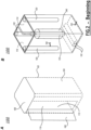
- FIG. 1 shows a disinfection system 100 in an exemplary operating environment.
- Disinfection system 100 includes a disinfection chamber 110 having an interior volume 112.
- One or more radiation sources 120 are coupled to the interior volume 112, and these radiation sources 120 are directed by a processing unit such as controller 140 to emit radiation light rays into interior volume 112 when in operation.
- One or more radiation sensor circuits 130 are physically, communicatively, electronically, or otherwise coupled within interior volume 112 and arranged to detect radiation within interior volume 112.
- One or more non-radiation detection sensor circuits 132 are physically, communicatively, electronically, or otherwise coupled within interior volume 112 and arranged to detect non-radiation parameters such as intensity, time, volume, and the like within interior volume 112.
- Also arranged within the interior volume is at least one independent monitoring circuit 134.
- the independent monitoring circuit 134 is arranged to validate the proper operation of the at least one radiation sensor circuit 130.
- the one or more sensor circuits 130, 132, and monitoring circuits 134 may be arranged in a manner specifically for a certain type of target article 240 ( FIG. 2B ) to be disinfected in disinfection chamber 110.
- sensor circuits 130 may be arranged in a manner suitable for detecting radiation intensity information on the surface portions of a target article 240.
- sensor circuits arranged to detect disinfection radiation are referred to herein as sensor circuits 130, and sensor circuits that are arranged to validate the operation of the sensor circuits 130 are referred to herein as independent monitoring circuits 134.
- the independent monitoring circuits 134 are also arranged to detect disinfection radiation.
- sensor circuits arranged to detect other non-disinfection-radiation phenomena such as temperature, time, vibration, weight, humidity, liquid, continuity, and the like, are referred to herein as sensor circuits 132.
- the disinfection chamber 110 may also include one or more temperature sensor circuits, one or more foreign object detection sensor circuits (e.g ., infrared emitters and detectors, cameras, accelerometers, load cells, or the like), one or more "door open” sensor circuits (e.g ., normally-open or normally closed switches, light detectors, continuity circuits, or the like), or any other types of non-disinfection-radiation sensor circuits.
- These other, non-disinfection-radiation sensor circuits may each, individually or collectively, be referred to as sensor circuits 132.
- Controller 140 includes a disinfection exposure determination unit 142 and a disinfection operation control unit 144 arranged to execute a generated disinfection program. Besides the data exchange with disinfection chamber 110, radiation sources 120, sensor circuits 130, 132, and monitoring circuits 134, controller 140 may also communicate with one or more databases 124 and/or disinfection requirement inputs 122 in achieving its functions and operations.
- FIGS. 2A-2E are exemplary disinfection chambers, each of which may be referred to as an exemplary disinfection system 100.
- FIGS. 2A- 2E may be referred to collectively as FIG. 2 .
- components retain the same reference number, and in some cases, to avoid obscuring certain features, some of the reference numbers are shown in one figure, while the same reference numbers are not shown in other figures even when the particular component is present.
- disinfection system 100 is a high-level disinfection device that includes a disinfection chamber 110 having an interior volume 112 and one or more radiation sources 120 configured to emit radiation into the interior volume 112 of the disinfection chamber 110. At least some of the radiation sources 120 represented in FIG. 2 are optional. In FIG. 2B , for example, two optional radiation sources 120 at the bottom of the interior volume 112 are shown in dashed lines. In some cases, the two radiation sources 120 at the bottom of the interior volume 112 are included, in some cases, other radiation sources 120 are optionally included or omitted.
- the interior volume 112 of the disinfection chamber 110 may include one or more reflective surfaces 114 arranged to facilitate reflections of radiation light rays emitted from radiation sources 120 such that a rapid and low temperature disinfection is achieved.
- the reflective surface 114 is typically formed from one or more materials having at least 30% reflectivity. By “at least 30% reflectivity,” it is meant that no more than 70% of the incident UV radiation, particularly in the UV-C range, will be absorbed, and the rest of the incident radiation will be reflected via one or both diffuse and specular reflection.
- Reflective materials that may be particularly useful in a disinfection chamber include, but are not limited to, aluminum, glass, magnesium, stainless steel, polyvinyl alcohol, polytetrafluoroethylene, substrate materials treated with barium sulfate-containing paints, and alloys, derivatives, and copolymers thereof.
- the reflective surface comprises aluminum, polished to a "Grand Brilliant" condition.
- the reflective surface may be formed using polytetrafluoroethylene PTFE, or PTFE and similar polymers may be coated by various means onto another substrate, to form the reflective surface.
- the reflective interior surfaces of the disinfection chamber are formed to be as reflective as available manufacturing techniques provide. Such an approach facilitates disinfection processes that utilize high intensity disinfection radiation carried out at low temperatures.
- the interior surfaces of the interior volume 112 may be positioned and shaped to reduce the absorption of UV radiation by the interior surfaces and instead reflect and redirect the UV radiation within the interior volume 112 of disinfection chamber 110 and onto the one or more target articles 240 positioned within the interior volume 112.
- the material choice and configuration of the interior volume 112 of disinfection chamber 110 may be selected to promote preferential extinction of certain UV or other wavelengths of electromagnetic energy that can contribute to increased temperatures within the interior volume 112 ( i.e ., longer wavelengths of radiation). That is, the shape of the interior volume 112 may contribute to the quick and efficient directing of radiation to the target article 240.
- the radiation passing through the middle of the interior volume 112 of the disinfection chamber 110, where the target article 240 is to be positioned, and the reflective material(s) employed in the interior volume 112 may contribute to the reflection (e.g., re-radiation or re-emission) of radiation with low loss (i.e ., approximately the same amount of energy returns from the surface as was incident).
- the interior walls of the interior volume 112 are constructed and configured to provide low loss of UV-C radiation emitted from the one or more UV radiation sources 120 (not specifically shown in FIG. 2A for simplicity purposes).
- Such embodiments increase the likelihood that radiation (e.g ., UV-C radiation) useful for disinfection will be reflected one or more times inside the chamber until the radiation impinges upon the article to be disinfected where it may be absorbed and extinguished, reflected, or re-emitted.
- an improved utility is made of the useful radiation band energy (e.g ., UV-C radiation band energy) in disinfecting the target article 240 ( e.g ., medical device or instrument), while reducing the amount of thermal heating of the target article 240.
- the disinfecting radiation utilized can be UV-C radiation, and in embodiments that utilize UV-C radiation, the one or more radiation sources 120 may be any commercially available device suitable for emitting sufficient UV-C radiation to carry out high-level disinfection. Where one source 120 of UV-C radiation is coupled to the disinfection chamber 110, that source 120 will emit sufficient UV-C radiation into the interior volume 112 of the disinfection chamber 110 to carry out high-level disinfection as detailed herein. Where two or more sources of UV-C radiation are coupled to the disinfection chamber 110, the UV-C radiation sources 120 may each be capable of emitting sufficient UV-C radiation to carry out high-level disinfection.
- such radiation sources 120 may each, on their own, emit insufficient UV-C radiation to achieve high-level disinfection, but when the individual outputs of UV-C radiation emitted from the two or more sources 120 are combined, the total output of UV-C radiation is sufficient to achieve high-level disinfection.
- Each radiation source 120 may be coupled to interior volume 112 through various approaches.
- radiation source 120 may be locally attached to interior volume 112 to emit UV-C radiation rays into interior volume 112, as shown in FIG. 2B for illustrative purposes.
- a radiation source 120 may be remotely coupled to interior volume 112.
- radiation source 120 may be a standard laser, or solid state laser photodiode, and may be employed as a source of disinfecting energy for a stand-alone disinfection chamber 110, along with appropriate optical conductors and couplers to emit UV-C radiation rays into interior volume 112.
- a direct or conducted source of UV radiation could be steered, via a mirror or other device, or scanned along a target article 240 positioned within interior volume 112.
- disinfection chamber 110 may include a moveable attachment assembly, which is not specifically shown to avoid unnecessarily cluttering the figure, within interior volume 112 such that a target article 240 may be positioned on the moveable base and may be moved past a stationary radiation emission region.
- a processing unit of controller 140 may control the radiation source 120 and the moveable base to rotate or move in opposite directions to provide preferential exposure of the target article 240 to the UV radiation.
- UV-C radiation As the disinfecting radiation within the disinfection chamber, this is for illustrative purposes only.
- the radiation or energy used in the disinfection system 100 may also be or include UV-A radiation, UV-B radiation, or even non-UV radiation, alone or in various combinations. It is to be further understood that, within the interior volume 112, exposure of the articles to UV radiation may be carried out in a variety of ways.
- a flash source of energy emits extremely high intensity disinfecting radiation.
- the flash source of energy can provide high-level disinfection of one or more contaminated articles in an acceptably short period of time.
- a flash source of energy may deliver disinfecting radiation to the one or more articles at such a high rate that high-level disinfection is achieved in period of time selected from 10 seconds or less, 5 seconds or less, 3 seconds or less, and 2 seconds or less.
- a flash source of energy as contemplated herein may be selected to deliver any selected disinfecting radiation.
- one radiation source 120 of disinfecting radiation may be all that is needed in the interior volume 112 of disinfection chamber 110.
- the radiation emitted by the flash source may first strike a surface that will spread and distribute the radiation before hitting the target.
- the target will receive primarily indirect rather than direct, illumination.
- the disinfection device could be configured so that the source or sources, of any appropriate type, are located in a different part of the device than the target. Since the energy spectrum emitted by some types of flash sources may be broad, it may be helpful to interpose a filter between the source and the target so only the spectrum of interest is allowed to pass to the disinfection chamber.
- the one or more UV radiation sources 120, the one or more UV radiation sensor circuits 130, and/or the one or more independent monitoring circuits 134 are positioned within the interior volume 112 of disinfection chamber 110 in a manner that facilitates and validates rapid, low temperature disinfection.
- the configuration of the disinfection chamber, the sources of disinfecting radiation, and the sensors detecting disinfecting radiation will be selected to provide and confirm a selected exposure of the one or more articles to radiation and/or optimize transmission of radiation from the one or more sources to efficiently and reproducibly target an article.
- a disinfection chamber 110 may be coupled to a single radiation source 120 of disinfecting radiation, such as one UV-C radiation source.
- the radiation source may be positioned on a top or bottom of the chamber.
- the single radiation source 120 may be positioned on a side of the disinfection chamber or, where the disinfection chamber includes multiple sides, at an intersection formed at an intersection of two sides.
- the devices and systems described herein are not limited to disinfection chambers having a single source of disinfecting radiation.
- the disinfection chamber 110 included in the devices and systems 100 according to the present description may utilize multiple radiation sources 120, of the same or different variety, and different embodiments of a disinfection chamber 100 having multiple sources 120 of disinfecting radiation are detailed herein and illustrated in the accompanying figures. Such embodiments may be advantageous where the surface of the one or more target articles 240 to be disinfected are more complex than a single flat surface.
- a target article 240 to be disinfected such as an endotracheal probe or an ultrasound probe, may have two or more of a front, back, lateral, and dorsal and/or ventral surface that require disinfection.
- the radiation sources 120, and other structures are arranged to disinfect one particular type of target. That is, the sources 120 and/or other structures may provide illumination to each surface of the specific target, but the device would not function effectively if a different type of target was placed in the disinfection chamber.
- one or more lasers or photodiodes, or arrays of sources, or combinations of types of sources designed to emit UV-C light may be used to deliver disinfecting radiation within the disinfecting chamber.
- the one or more sources of UV-C radiation included in the disinfection chambers 110 described herein provide a total UV-C output within the interior volume 112 of the disinfection chamber 110 that is selected to be at least 5 Watts of radiant power. Selection of such a radiation source, which can deliver a high-power dose of radiation, may be preferred to shorten a disinfection cycle. That is, by selecting a high-power radiation source, the energy is delivered rapidly, which may reduce the duration of radiation exposure and also reduce the amount of heat generated by the radiation.
- the one or more radiation sources 120 may be selected to provide a total UV-C output within the chamber's interior volume 112 selected from at least 10 W, at least 15 W, at least 20 W, at least 25 W, at least 30 W, at least 40 W, at least 50 W, at least 75 W, at least 90 W, and at least 100 W of radiant power.
- the frequency band of UV-C light emitted from the one or more sources may be selected from between about 240 nm and about 270 nm and between about 255 nm and about 265 nm.
- FIGS. 2C, 2D, and 2E are additional exemplary disinfection chambers.
- a processing unit of the controller 140 ( FIG. 1 ) is arranged to execute computer instructions that, when executed by the processing unit, cause the processing unit to direct a delivery of a disinfection dose of the radiation into the interior volume 112 of the disinfection chamber 110.
- Each of the embodiments in FIGS. 2C-2E includes two radiation sensor circuits 130 configured to detect the radiation within the interior volume 112 of the disinfection chamber 110. The radiation sensor circuits 130 are further configured, based on how much of the radiation is detected, to determine when said disinfection dose has been delivered.
- the processing unit of controller 140 executes computer instructions that cause the processing unit to direct at least one radiation source 130 to begin emitting the radiation into the interior volume 112 of the disinfection chamber 110.
- the radiation sensor circuits 130 work cooperatively with the controller 140 to accumulate radiation samples, mathematically combine (e.g., generate an accumulated radiation value via an average or in some other way) the accumulated samples, apply one or more calibration factors, scaling factors, or other factors, and determine whether or not the disinfection dose of radiation has been achieved.
- the accumulated radiation value at one or more radiation sensor circuits represents an amount of radiation detected by the at least one radiation sensor circuit, and a comparison if performed to verify that the accumulated radiation value, which may be representative of a single radiation sensor circuit or a collection of radiation sensor circuits, reaches a first radiation threshold. If the radiation threshold is reached, the processing unit of the controller 140 will direct the at least one radiation source 120 to stop emitting the radiation into the interior volume 112 of the disinfection chamber 110.
- the independent monitoring circuit 134 is arranged along the lines of the radiation sensor circuits 130.
- the independent monitoring circuits 134 and radiation sensor circuits 130 are formed along the same lines, but data from the two different types of circuits is processed differently.
- a disinfection chamber 100 is arranged with two radiation sensor circuits 130 and one independent monitoring circuit 134.
- Each of the circuits may include a photodiode circuit which may include operative voltage divider circuitry, power supply circuitry, analog-to-digital conversion circuitry, and other such circuitry.
- each photodiode circuit may receive and accumulate a different amount of radiation.
- the difference in received radiation may be proportionally determined, calculated, or otherwise known. In this way, it is possible to determine how much accumulated radiation is received at each photodiode, and using these accumulated values, it can be determined within a selected validation threshold if the other photodiodes received the "proper" or otherwise correct amount of radiation.
- the first location of the first radiation sensor circuit 130 e.g ., photodiode
- the second location of the second radiation sensor circuit 130 e.g ., photodiode
- the third location of the independent monitoring circuit 134 are separated and not in close proximity.
- the first location of the first radiation sensor circuit (e.g ., photodiode) and the third location of the independent monitoring circuit 134 are in close proximity.
- the second location of the second radiation sensor circuit 130 (e.g ., photodiode) and the third location of the independent monitoring circuit 134 are in close proximity.
- the monitoring sensor 134 is arranged to operate independently from the radiation sensor circuits 130.
- the processing unit of controller 140 ( FIG. 1 ) is arranged to receive first radiation information from at least one of the radiation sensor circuits 130 and arranged to not receive second radiation information from the independent monitoring circuit 134.
- a second independent processing unit may be arranged to receive radiation information from the independent monitoring circuit 134 and arranged to not receive radiation information from the at least one of the radiation sensor circuits. That is, each of the radiation sensor circuits 130 and independent monitoring circuits 134 communicates its accumulated radiation values to different processing units. In at least one case, information regarding the accumulated radiation values may be communicated to different processing units, various resulting information may be communicated back to a common processing unit.
- the radiation sensor circuits 130 and independent monitoring circuits 134 may have separate and distinct power supplies.
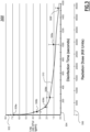
- FIG. 3 is an exemplary kill curve 300.
- Energy Fluence Rate may be understood by those of skill in the art as the flow of energy in watts per square meter (Watts/m 2 ), which in the present disclosure is photonic energy in the UV wavelength range, coming from all directions through or across an infinitesimally small sphere of unit area (1) within the interior volume 112 of the disinfection chamber 110. Integrating this energy flow over this surface and over time calculates a "dose" in Joules (J) that has been delivered from the radiation sources 120 and delivered, presumably, at the surface of the target article 240.
- Joules J
- This energy may be absorbed and extinguished, re-emitted, reflected/scattered, or captured and transported elsewhere.
- the dose of energy delivered to the point or surface is the integral (i.e ., summation) of the irradiance over the total exposure.
- irradiance in W/m2
- fluence in a situation where all inbound radiation is coming from a single direction and impinging onto a surface, irradiance and fluence are identical.
- the terms "fluence” and "irradiance” may be used interchangeably, although it is recognized that amongst the two terms, there are differences.
- the present disclosure in at least some embodiments, is concerned with radiation impinging on an elemental unit of surface from one side, entering from a hemisphere of angle. That is, radiation is not reaching the surface from the rear as it is blocked by the target object. Inbound radiation can impinge on the surface substantially normal ( i.e ., perpendicular) to the surface element, as well as at all other angles of incidence up to +/- 90°.
- a broad or narrow range of angles of inbound radiation may be suitable sampled. When the angle is narrow, fluence is essentially identical to irradiance.
- a detector When measuring radiative power at a location within the chamber to assess the amount of total (e.g ., aggregated) energy impinging on a surface, a detector with a very wide angle of acceptance may be selected. Further, inlet optics on detectors may be fitted with filters to permit passage and thus measurement only of radiation of the desired disinfecting wavelength. This information is then incorporated into the algorithms and models when correcting the predicted fluence levels with those measured in the chamber or at the surface of a test device.
- a target article ratio can be established between the radiation dose received at a specific point (e.g ., a region of interest such as a determined "cold spot") on the target article 240 and the dose measured by sensors 130 inside the interior volume 112 of the disinfection chamber 110 (e.g. , average dose, accumulated dose, point-specific dose, or the like).
- a specific point e.g ., a region of interest such as a determined "cold spot
- the dose measured by sensors 130 inside the interior volume 112 of the disinfection chamber 110 e.g. , average dose, accumulated dose, point-specific dose, or the like.
- the proportionality of irradiance ratios in the disinfection chamber 110 are then used to adjust (e.g ., increase or decrease) a base radiation dose that would acceptably disinfect a standard surface (e.g ., a test carrier inoculated with a known amount of a particular pathogen, distributed over a defined surface, during disinfectant potency testing) to a determined confidence level that a sufficient dose of radiation is received at the surface of the target article 240 (e.g., an ultrasound probe) intended for disinfection.
- a standard surface e.g a test carrier inoculated with a known amount of a particular pathogen, distributed over a defined surface, during disinfectant potency testing
- Disinfection of target article 240 placed in the center of the disinfection chamber 110 is achieved when the surfaces of the target article 240 that are intended for disinfection actually receive sufficient fluence to achieve high-level disinfection (i.e., a desired log reduction of viable pathogen).
- the value of the fluence received at each point on the target article's surface at a particular point in time may be measured by optical instrumentation and a discrete step-wise mapping process.
- Embodiments of the disinfection system 100 have been characterized by such mapping where irradiance levels were measured at multiple locations. This mapping provides confirmation of the incoming radiation arriving at locations where the surfaces of particular target articles 240 (e.g ., ultrasound probes) would be positioned.
- FIG. 3 the results of at least one study of effectiveness of the disinfection system 100 discussed in the present disclosure are illustrated.
- the inventors have performed detailed and extensive testing of such effectiveness against a number of pathogens including Bacillus subtilis , Clostridium sporogenes , and many others. Exemplary results are presented in FIG. 3 , and the exact spore represented by the kill curve 300 is not relevant to the discussion. Instead, the teaching of FIG. 3 illustrates that the radiation used in the present disinfection systems kills very rapidly early in the disinfection cycle as the pathogen is directly impinged upon by the radiation. As time passes, killing off the last 2 logs of viable pathogen survivors may require extension of the disinfection cycle.
- One theory for this is that the pathogen entities neutralized early in the disinfection cycle physically shield surviving pathogen spores from at least some inbound radiation. Neutralizing these remaining survivors that are "buried" beneath the earliest affected spores requires longer radiation exposure.
- a vertical axis 302 is a logarithmic representation of a number of viable pathogen spores present in a determined area of a target article (i.e., a negative binomial distribution of colony forming units (nb.CFU)) per target article 240 (tgtArt).
- a first horizontal axis 304 represents an elapse of time (e.g ., a disinfection cycle duration) over which a disinfection cycle is performed. The first horizontal axis 304 is measured in seconds, but other time units could also have been selected.
- a second horizontal axis 306 of the kill curve 300 in FIG. 3 which is below the first horizontal axis 304, represents an accumulation of radiation dose (e.g ., energy fluence integrated over the exposure) delivered to a surface of target article 240 during a disinfection cycle.
- the accumulation of radiation is generally linear over time in FIG. 3 , but it is recognized that other disinfection programs may alter the delivery of radiation in any way, which could change the distribution of energy fluence over time.
- the measure of radiation dose in FIG. 3 is disinfection or "kill units," which is purposefully a non-limiting, non-standard unit chosen for the exemplary illustration.
- the disinfecting action of a type of radiation may sterilize a pathogen leaving it alive but non-viable, which at least in the present disclosure means that it cannot reproduce. Hence the pathogen is disinfected, but not necessarily "dead.”
- the term kill unit may be understood as an accumulation of "counts” that describes the overall radiation exposure delivered in the interior volume 112 of the disinfection chamber 110 over a given cycle.
- data signals from radiation sensor circuits 130 e.g ., photodiodes
- These values may be corrected by one or more calibration factors and summed over the course of the radiation exposure using, for example, a processing unit of the controller 140.
- a determined amount of radiation e.g ., a total amount of radiation to a selected surface in Joules, or in some cases, an area-specific dose in e.g ., Joules/cm 2
- the term, kill units has been selected to convey the relevant teaching of FIG. 3 .
- kill curve 300 may sometimes also be referred to in the art as a "survivor curve.”
- one reason to deliver a high-power dose of radiation is to shorten a disinfection cycle time. This is because radiation very rapidly kills/disinfects a substantial portion of the pathogen early in the disinfection cycle. By applying radiation at high power levels, the energy can be delivered quickly, which can shorten the disinfection cycle time. This has the added advantage of reduced opportunity for thermal heating of the target article 240.
- a mean 5 log 10 reduction of pathogen is achieved in the first 150 seconds via delivery of about 5000 KU
- a mean 6 log 10 reduction of viable pathogen is achieved in after only 650 seconds and delivery of about 9300 KU.
- each radiation source 120 may have characteristics that cause the respective source to radiate at different power levels even when the output power of two or more radiation sources 120 is otherwise expected to be the same.
- Each radiation source 120 may also emit radiation light rays at different angles, substantially parallel to each other, or a combination of attitudes in operation.
- a plurality of radiation sources may be controlled with common signals and common parameters.
- two or more radiation sources may be independently controlled via independent control signals and parameters.
- a disinfection chamber 110 as described herein may be configured to create a plurality of disinfection regions within the interior volume 112.
- the disinfection chamber 110 and/or one or more target articles 240 to be disinfected can be further configured such that the one or more target articles 240 to be disinfected are positioned within the disinfection regions in selected positions, alignments, orientations, or the like.
- the term "disinfection region" refers to a region within the disinfection chamber wherein a certain intensity of disinfecting radiation is delivered over the course of a disinfection operation.
- substantially uniform surface irradiation refers to a disinfecting region wherein the intensity at which the disinfecting radiation is delivered to the surface(s) of the article to be disinfected does not vary across any portion of those surface(s) by more than an amount selected from ⁇ 30%, ⁇ 25%, ⁇ 20%, ⁇ 15%, ⁇ 10%, and ⁇ 5% or another like value.
- the disinfection regions may be re-defined or custom-tuned for different types of target articles 240, different regions of target articles 240 intended for disinfection, different operational states of radiation sources 120, or for other reasons. Further, the disinfection regions may be dynamically adjusted, collectively adjusted, independently adjusted, or adjusted in some other way.
- sources 120 of disinfecting radiation can be positioned on or within any sidewall, top wall, bottom wall, or at any junction between any of two or more sidewalls, a sidewall and a bottom wall, and a sidewall and a top wall.
- a generated disinfection program may control one or more radiation sources 120 to deliver one or more desired levels of radiation to one or more different disinfection regions defined in the interior volume 112 of the disinfecting chamber 110. And the radiation intensity delivered to one disinfection region may concurrently be different from the radiation intensity delivered to another disinfection region.
- the interior volume 112, or portions thereof may be shaped as a circle, a parabola, a double ellipse, or some other shape.
- interior walls 230 of the interior volume 112 may be added, removed, or alternatively or in addition re-positioned so that a disinfection chamber having an interior volume defined by a first cross-sectional shape is modified to have an interior volume defined by a second, different cross-sectional shape.
- the rated total power delivered by the source tubes may range from about 20 W to about 200 W.
- the input electrical power consumed by disinfecting radiation source(s) 120 e.g., UV tubes
- the input electrical power consumed by disinfecting radiation source(s) 120 is related and informative of the output UV power delivered from these sources, but it is noted that the relationship is not linear, and the relationship will generally change over time.
- the input power for UV tubes used in a disinfection chamber as described herein may be selected from, for example, 20 W, 25 W, 30 W, 35 W, 40 W, 45 W, 50 W, 55 W, 60 W, 65 W, 70 W, 75 W, 80 W, 85 W, 90 W, 95 W, 100 W, 135 W, 150 W, or another like value.
- one or more sources 120 of disinfecting radiation may be positioned at one or more corners of the sidewalls.
- the disinfection chamber includes at least one top or bottom wall or surface
- one or more sources 120 of disinfecting radiation can be positioned at a top and/or bottom wall or surface to provide a certain level of irradiance of disinfecting radiation directed into one or more disinfection regions formed within the interior volume 112.
- the disinfection chamber 110 can be provided with a moveable base, e.g ., a suspension assembly, which positions one or more target articles 240, e.g., an ultrasound probe or other medical instrument, within the chamber.
- a suspension assembly as described herein works to position one or more articles to be disinfected consistently within the disinfection chamber.
- the disinfection chamber is designed to create one or more disinfection regions, providing a suspension assembly allows consistent, repeatable positioning of the one or more articles to be disinfected within disinfection region(s), thereby ensuring the one or more articles are subjected to high intensity radiation during a disinfection cycle.
- interior volume 112 the positions of the shape and size of interior volume 112, the position, shape, and light reflective properties of reflective interior sidewalls that define interior volume 112, the amount and positions of radiation sources 120, the movement of moveable base and other structural configurations of interior volume 112 may all affect the radiation intensity delivered to a disinfection region within interior volume 112.
- structural configurations all such structural configurations of and/or within interior volume 112 are referred to as "structural configurations" of interior volume 112.
- Each of the one or more radiation sensor circuits 130, other non-radiation-based circuits132, and independent monitoring circuits 134 included in the interior volume 112 may be capable of detecting and communicating information such as a total radiation dose, a rate of exposure over time, and the like, to a processing unit of controller 140 ( FIG. 1 ).
- the radiation sensor circuits 130 may sense the UV-C dose received by the target article 240 and/or the amount of UV-C radiation emitted by one or more UV-C sources 120 included in the disinfection device.
- FIG. 4 is a system embodiment of a disinfection system 100A with an independent monitor circuit.
- the embodiment of FIG. 4 is arranged to illustrate the flexibility of the present teaching.
- An independent monitoring circuit 134 is arranged to monitor 134M the operations of the one or more radiation sensor circuits 130.
- the one or more radiation sensor circuits 130 are arranged to determine, based on how much of the radiation is detected, when a sufficient disinfection dose has been delivered to an object in the disinfection chamber, and the independent monitoring circuit 134 will validate the proper operation of the one or more radiation sensor circuits 130.
- a controller 140 is represented in FIG. 4 .
- the controller 140 is optionally arranged to include one or more cooperative or independent processing units including a processing unit 140A and a second processing unit 140B.
- Bidirectional control signals, data signals, or control signals and data signals are communicated between the controller 140 and the independent monitoring circuit 134 via a bus 140C.
- the bus 140C includes direct, peer-to-peer communication link such as a serial peripheral interface (SPI) communication link.
- SPI serial peripheral interface
- Other forms of bus communication means are also contemplated.
- the disinfection device of the embodiment in FIG. 4 may be configured and optionally reconfigured in any suitable way.
- controller 140 may include only a single processing unit such as processing unit 140A.
- the single processing unit 140A will carry out the operations of the independent monitoring circuit 134 and the one or more radiation sensor circuits 130.
- the single processing unit 140A in this case will manage the operations of the circuits to direct the at least one radiation source 120 to begin emitting the radiation into the interior volume of the disinfection chamber, and later direct the at least one radiation source 120 to stop emitting the radiation into the interior volume of the disinfection chamber.
- the single processing unit 140A may also generate an accumulated radiation value that represents an amount of the radiation detected by the at least one radiation sensor 130, and verify via the independent monitoring circuit 134 that the accumulated radiation value has reached a first radiation threshold.
- the single processing unit 140A may execute concurrent instances of the same algorithm to generate dose information based on collected radiation data. That is a first set of radiation data may be collected by the independent monitoring circuit 134, and a second set of radiation data may be collected by the one or more radiation sensor circuits 130.
- the two sets of radiation data may be stored in the same or different repositories. In this way, the single processing unit 140A may independently execute a first instance of a radiation accumulation algorithm and a second instance of the radiation accumulation algorithm.
- the first instance of the radiation accumulation algorithm can be executed using first radiation information captured by the at least one radiation sensor circuit 130, and the second instance of the radiation accumulation algorithm can be executed using second radiation information captured by the independent monitoring circuit 130.
- the single processing unit 140A can determine a validation result based on a comparison of the first accumulated radiation value to the second accumulated radiation value, and based on the validation result, the single processing unit 140A can assert a validated disinfection signal, an error signal, or some other signal.
- a system may selectively separate functions of the independent monitoring circuit 134 and the one or more radiation sensor circuits 130. Such a selective separation may be based on a more efficient or otherwise improved use of computing resource, a government regulation, or some for some other reason.
- a first processing unit 140A is arranged to detect and otherwise capture radiation information from the interior volume of the disinfection chamber via the independent monitoring circuit 134. The captured information may then be presented to a single processing unit of the controller 140 that carries out the disinfection operations of the disinfection chamber, including the operations of the one or more radiation sensor circuits 130, and also carries out the monitoring operations of the independent monitoring circuit 134.
- a second processing unit 140B may be optionally arranged to detect and otherwise capture radiation information from the interior volume of the disinfection chamber via the one or more radiation sensor circuits 130. The captured information may then be presented to a single processing unit of the controller 140 that carries out the disinfection operations of the disinfection chamber, including the operations of the one or more radiation sensor circuits 130, and also carries out the monitoring operations of the independent monitoring circuit 134.
- a first processing unit 140A is arranged to carry out all of the computing functions of the independent monitoring circuit 134
- a second processing unit 140B is arranged to carry out all of the one or more radiation sensor circuits 130.
- any one of the processing units of controller 140 may compare the generated values and determine a validation result. In some cases, if the two independently determined radiation dose values are within ten percent (10%) of each other, then the disinfection operation is deemed a success, and a validated-disinfection-signal is asserted. In these cases, if the two independently determined radiation dose values are not within ten percent (10%) of each other, then the disinfection operation is deemed a failure. A signal indicating success or failure, as the case may be, can then be asserted.
- determining a successful disinfection dose delivery may be based on any suitable "closeness" of the determined accumulated radiation value of the independent monitoring circuit 134 to the determined accumulated radiation value of the one or more radiation circuits 130.
- a successful determination of a valid disinfection dose delivery may be based on a closeness of two percent (2%) or less, five percent (5%) or less, or twenty percent (20%) or less. Any other desirable closeness or mechanism to determine such closeness may be implemented.
- an independent monitoring circuit 134 is coupled to a first processing unit 140A, and one or more radiation sensor circuits 130 are coupled to a second processing unit 140B.
- the first and second processing units 140A, 140B are separate and distinct in this embodiment.
- a medical practitioner has started a disinfection process and a target object is in the disinfection chamber.
- the determination of a disinfection dose is made as described herein, and the controller 140, via one of the first and second processing units 140A, 140B, or via some other processing unit will pass communication signals 140E, 140F to direct a module 148A to begin the disinfection cycle.
- the one or more radiation sources 120 Upon receiving such signal, the one or more radiation sources 120 will perform local safety checks (e.g ., disinfection chamber door closed, an absence of foreign objects in the disinfection chamber, and other such safety checks, and direct the one or more radiation sources 120 to begin emitting radiation.
- the second processing unit will administer the operations of the one or more radiation sensor circuits 130.
- a first logic module 140A and a second logic module 140F will monitor the disinfection cycle, which may include accumulating radiation data values with first and second photodiode circuits, respectively.
- One or more calibration factors may be applied during the generation of an accumulated radiation value.
- the raw or accumulated radiation values from a first radiation sensor circuit e.g ., at a first logic module 140A
- Processing in a first radiation sensor circuit falls via 140B to a determination module 140C, and processing in a second radiation sensor circuit falls via 140G to a determination module 140H.
- the determination module or module 140C, 140H cooperate to determine whether or not the accumulated radiation value has reached a first radiation threshold.
- the first radiation threshold will represent the minimum dose of radiation as described in the present disclosure. If the minimum dose has been delivered (i.e., the accumulated radiation value has reached the first radiation threshold), then the controller 140 will direct a logic module 148B to direct the at least one radiation source 120 to stop emitting radiation into the interior volume of the disinfection chamber. Control is passed to the controller 140 via signals 140D, 1041, or signals 140D and 1401.
- Processing in the independent monitoring circuit 134 in the present embodiment is administered by the first processing unit 140A.
- the independent monitoring circuit 134 will also accumulate radiation information using, for example, a third photodiode circuit arranged to capture radiation reading from the interior volume of the disinfection chamber.
- the accumulated radiation information may be processed by the application of one or more calibration values, scale factors, or any other suitable adjustment mechanism.
- the system includes a disinfection chamber 110 ( FIG. 1 ) having an interior volume 112 ( FIG. 1 ), a radiation source 120 configured to emit radiation into the interior volume 112 of the disinfection chamber 110, a radiation sensor circuit 130 to detect the radiation within the interior volume 112 of the disinfection chamber 110, an independent monitoring circuit 134 arranged to detect the radiation within the interior volume 112 of the disinfection chamber 110, and a computing device such as controller 140.
- the controller 140 includes a memory arranged to store first radiation values captured by the radiation sensor circuit 130, second radiation values captured by the independent monitoring circuit 134, and computer instructions.
- the computer instructions are executed by a processing unit (e.g ., any one or more of controller 140, first processing unit 140A, and second processing unit 140B), which causes the processing unit to direct the radiation source 120 to start emitting the radiation into the interior volume 112 of the disinfection chamber 110.
- the processing unit will also generate a first accumulated radiation value based on the first radiation values stored in the memory, and generate a second accumulated radiation value based on the second radiation values stored in the memory.
- the processing unit will direct the radiation source 120 to stop emitting the radiation into the interior volume 112 of the disinfection chamber 110 after the first accumulated radiation value has reached a first radiation threshold.
- the processing unit will determine a validation result based on a comparison of the first accumulated radiation value to the second accumulated radiation value, and the processing unit will assert at least one of a validated disinfection signal and an error signal based on the validation result.
- a first photodiode is arranged in the radiation sensor circuit, a second photodiode is arranged in the radiation sensor circuit, and a third photodiode is arranged in the independent monitoring circuit.
- the processing unit is further arranged to execute the computer instructions which, when executed by the processing unit, cause the processing unit to generate the first accumulated radiation value from a mathematical combination of first radiation information captured by at least the first and second photodiodes, and generate the second accumulated radiation value from second radiation information captured by the third photodiode.
- the processing unit will first apply at least one first calibration factor during the generation of the first accumulated radiation value, and apply at least one second calibration factor during the generation of the second accumulated radiation value.
- the processing unit includes at least two different processors, and the at least two different processors include a first processor arranged to receive first radiation information from the radiation sensor circuit and a second processor arranged to receive second radiation information from the independent monitoring circuit.
- FIG. 5 is another system embodiment of a disinfection system 100B with an independent monitor circuit.
- each disinfection system 100, 100A, 100B embodiment may be referred to as a disinfection system 100 except where the context of such embodiment is clearly directed to one of the embodiments discussed in the present disclosure.
- the disinfection system 100B includes a controller 140 embodiment and a set of hardware circuitry 180.
- Other components of the disinfection system 100B such as the housing, interior volume, target device hanging mechanism, and the like are included in the disinfection system 100B as would be understood by one of ordinary skill in the art, but these components are not shown to avoid obscuring the features of interest discussed in FIG. 5 .
- a controller 140 includes any number of processing units 140A, 140B, 140N, which for brevity may be referred to individually or collectively as a processing unit 140.
- the controller 140 also includes a memory 160, which may be a single memory device or a plurality of memory devices, of any suitable architecture, in any suitable arrangement.
- the memory 160 is along the lines of memory discussed herein, which may be local to the controller 140, remote from the controller 140, distributed amongst a plurality of computing devices, or arranged in another way.
- the memory 160 includes computer instructions (e.g ., software, firmware, microcode, or the like) executable by one or more of the processing units 140, parameters, and any other selected information (e.g ., security information, encrypted or otherwise protected information, device identification information, default parametric information, and the like).
- the memory 160 includes any number of logic modules arranged to carry out the functions of the disinfection system 100B. In some cases, at least some of the logic modules are grouped or otherwise arranged. For example, memory 160 in FIG. 5 is illustrated as including one or more sensor circuit controls 130B and one or more independent monitoring circuit controls 134B.
- the one or more independent monitoring circuit controls 134B are represented in dashed lines indicating that such controls may optionally be arranged in the same memory as other functions of the disinfection system 100B, or the one or more independent monitoring circuit controls 134B may retain additional independence when arranged in a separate and distinct memory device.
- the memory 160 may include any number of logic modules.
- the memory 160 includes at least a dose calculation logic module 174, a user interface logic module 176, and an additional control logic module 178.
- the one or more sensor circuit controls 130B include logic modules to operate or otherwise control the various sensors (e.g ., radiation detection sensors 130, non-radiation detection sensors 132) of the disinfection system 100B.
- the logic modules include a calibration logic module 162, an accumulate-radiation-information module 164, and a determine-disinfection-dose-delivered module 166.
- the one or more independent monitoring circuit controls 134B include logic modules to operate or otherwise control the circuitry of one or more independent monitoring sensors.
- the logic modules include an accumulate-radiation-information module 168, a validate-radiation-sensor-circuits module 170, and a take-action module 172.
- the disinfection system 100B of FIG. 5 includes operative hardware logic 180.
- the operative hardware logic 180 may include any number of radiation sources 120 and any number of radiation detection sensors 130 as described in the present disclosure, and the hardware logic 180 may further include power supply circuitry 146 ( e.g., a single power supply or two or more shared or independent power supply circuits) as discussed in the present disclosure.
- the hardware logic may further include a user interface 182, analog-to-digital conversion (ADC) circuitry 184, any number of shared or independent clock circuits 186, and other circuits 188.
- ADC analog-to-digital conversion
- the user interface 182 hardware cooperates with the user interface logic module 176 to permit human or programmatic interaction with disinfection system 100.
- the interaction may be arranged to accept input such as target device identification information, timed-dose information (e.g ., a manually entered time that directs how long a target device in the disinfection chamber will be exposed to radiation), and other selectable information.
- the interaction may be further or alternatively arranged to communicate success or failure information, history information identifying operations of the disinfection system 100, system parameters, system results, and the like.
- the user interface 182 and user interface control logic module 176 may include or otherwise control input/output (I/O) circuitry and user interface (UI) circuitry that includes, without limitation, serial ports, parallel ports, universal serial bus (USB) ports, IEEE 802.11 transceivers and other transceivers compliant with protocols administered by one or more standard-setting bodies, displays, projectors, printers, keyboards, computer mice, microphones, micro-electro-mechanical (MEMS) devices such as accelerometers, and the like.
- the user interface 182 and user interface control logic module 176 may further include or otherwise control buttons, keypads, computer mice, memory cards, serial ports, bio-sensor readers, touch screens, and the like. These devices may, for example, input control information into the system.
- Displays, printers, memory cards, LED indicators, temperature sensors, audio devices (e.g ., speakers, piezo device, etc.), vibrators, and the like are all optionally included in the disinfection systems 100 described herein and useful to present output information to a medical practitioner operating the disinfection system 100.
- the input and output devices are directly coupled to the controller 140 and electronically coupled to a processing unit 140 or other operative circuitry.
- these user interface 182 devices pass information via one or more communication ports (e.g., RS-232, RS-485, infrared, USB, etc.).
- the analog-to-digital conversion (ADC) circuitry 184 is used to convert analog data to digital data.
- each radiation detection sensor 130 includes at least one photodiode and ADC circuitry 184 to repeatedly generate digital information that represents of the volume, strength, or other such photonic information detected and otherwise captured by the respective one or more photodiodes.
- Information from the ADC circuitry 184 is operatively used in at least the calibration logic module 162, accumulate-radiation-information module 164, and determine-disinfection-dose-delivered module 166.
- Such ADC information may also be used in the accumulate-radiation-information module 168, validate-radiation-sensor-circuits module 170, take-action module 172, and other modules of the disinfection system 100.
- the disinfection systems 100 described in the present disclosure may implement any number of shared or independent clock circuits 186, Clock circuits 186 may be used to measure timed doses of radiation, to limit sensor-based disinfection cycles for safety, to control user interface operations (e.g ., duration of audio output signals, a screen or display timeout, and the like), and to monitor or otherwise control other operations.
- Clock circuits 186 may be used to measure timed doses of radiation, to limit sensor-based disinfection cycles for safety, to control user interface operations (e.g ., duration of audio output signals, a screen or display timeout, and the like), and to monitor or otherwise control other operations.
- the other circuits 188 of the disinfection systems 100 described in the teaching herein may include, without limitation, door sensor circuits, illumination circuits, correct-target-device-placement circuits, foreign object detection circuits, scanner circuits, security circuits, automation circuits, memory controller circuits, and any other circuits included in the disinfection system 100.
- the dose calculation logic module 174 may be arranged to implement the minimum dose determination logic taught in the present disclosure. Accordingly, the dose calculation logic module 174 may account for determined cold spots on a particular target device, identification information representing a type of device, the placement of a target device in the disinfection chamber, the age or other parameters of the radiation sources 120, and any other information as described herein.
- the additional control logic module 178 is arranged to control other operations of the disinfection systems 100 that are not otherwise described herein, but which are known to one of ordinary skill in the art.
- Such other operations may include security operations (e.g. , encryption, decryption, time-in-service, calibration, fault detection, and the like), environmental sensor operations, operating system features, memory allocation and other such features, built-in-self-test (BIST) features, and the like.
- the accumulate-radiation-information module 168 and validate-radiation-sensor-circuits module 170 of the one or more independent monitoring circuit controls 134B are described throughout the present disclosure. As one of skill in the art will recognize, such features may implemented in any useful way to ensure with an acceptable level of confidence (e.g ., 98% certainty, 99% certainty, 100% certainty within a statistical margin of error established by a regulatory agency, and the like) that the one or more radiation detection sensors 130 have accurately determined that a minimum dose of disinfection radiation has been delivered to a target device.
- an acceptable level of confidence e.g ., 98% certainty, 99% certainty, 100% certainty within a statistical margin of error established by a regulatory agency, and the like
- HLD high-level disinfection
- a minimum dose of radiation is determined to be delivered to a device in the chamber, and in particular, the minimum dose of radiation is determined to be delivered to at least one region of interest (e.g ., a determined cold spot) of the device.
- This determination may be made, at least in part, using one or more sensors arranged to control the radiation delivery means in a way that confirms, with acceptable certainty, that the correct minimum dose was delivered during the cycle.
- systems according to the present description are operated according to one or more algorithms of the generated disinfection program for determining, calibrating, or adjusting one or more of the system conditions that cooperate to deliver the determined minimum dose to the target article.
- the one or more algorithms may include provisions to determine whether the minimum dose has been reached on all portions of a target article intended for disinfection.
- the one or more algorithms may be arranged to determine where, when, and how the disinfection conditions may be terminated (i.e., the "termination point" or "point for termination”).
- the one or more algorithms may be arranged to extend the process for irradiating the target article, or for signaling a point at which the disinfection conditions are terminated in order to avoid unwanted damage to the one or more target articles being processed.
- the disinfection system can be operated manually such that one or more operators are directed by a generated disinfection program to load one or more test articles within the disinfection device, initiate a disinfection cycle, monitor the system parameters necessary for execution of an algorithm utilized to determine the termination point for the cycle, and terminate the disinfection cycle according to the algorithm.
- the disinfection system can be operated semi-automated such that one or more of the tasks required for operation, such as, for example, monitoring of the system parameters, applying an algorithm to determine the termination point for a given disinfection cycle, or terminating a disinfection cycle, is automated or otherwise directed by a generated disinfection program.
- the disinfection system can be operated fully automated.
- a fully automated system is one in which, once a generated disinfection program is initiated by an operator, each of the subsequent steps through termination of the disinfection cycle are automated.
- the minimum dosage may be calculated based on any one or more of the radiation intensity map, the type of contaminants, the disinfection requirement and characteristics of the target article, the characteristics of the disinfection chamber, measured and/or calculated real-time data (e.g ., sensor data), and other such factors as discussed in the present disclosure.
- Methods for determining acceptable disinfection conditions for a given target article, microorganism, or type of contamination are also provided.
- methods described herein provide for setting and confirming operational parameters of the disinfection devices and systems described herein using test data collected for targeted microorganisms.
- the chosen or otherwise determined minimum dosage of radiation exposure serves to provide acceptable disinfection and serves to mitigate or otherwise reduce degradation of component materials and or joints or connections between components of the test articles being disinfected.
- the methods, devices, and systems provided are suited to eliminating a non-limiting, non-exhaustive range of microorganisms ("contaminants"), including, for example, mycobacterium species, Escherichia coli, Staphylococcus aureus, Tricophyton mentagrophytes, Pseudomonas aeruginosa, Enterococcus hirae, Bacillus subtilis, Bacillus cereus, Clostridium sporogenes, Candida albicans, orthopoxvirus, enterovirus, adenovirus type 5, and human papilloma virus.
- contaminants including, for example, mycobacterium species, Escherichia coli, Staphylococcus aureus, Tricophyton mentagrophytes, Pseudomonas aer
- the minimum dosage may be calculated based on any one or more of the radiation intensity map, the type of contaminants, the disinfection requirement and characteristics of the target article, the characteristics of the disinfection chamber, measured and/or calculated real-time data (e.g., sensor data), and other such factors as discussed in the present disclosure.
- Methods for determining acceptable disinfection conditions for a given target article, microorganism, or type of contamination are also provided.
- methods described herein provide for setting and confirming operational parameters of the disinfection devices and systems described herein using test data collected for targeted microorganisms.
- Example A-1 is a disinfection device, comprising: a disinfection chamber having an interior volume; at least one radiation source configured to emit radiation into the interior volume of the disinfection chamber; a processing unit arranged to execute computer instructions that, when executed by the processing unit, cause the processing unit to direct a delivery of a disinfection dose of the radiation into the interior volume of the disinfection chamber; at least one radiation sensor circuit configured to detect the radiation within the interior volume of the disinfection chamber and further configured, based on how much of the radiation is detected, to determine when said disinfection dose has been delivered; and an independent monitoring circuit arranged to validate a proper operation of the at least one radiation sensor circuit.
- the processing unit processes radiation information from the independent monitoring circuit.
- a second separate and distinct processing unit processes radiation information from the independent monitoring circuit.
- Example A-7 may include the subject matter of any of Examples A-1 to A-6, and alternatively or additionally any other example herein, wherein the at least one radiation sensor circuit and the independent monitoring circuit communicate radiation information to different processing units.
- Example A-8 described herein only as way of example, may include the subject matter of any of Examples A-1 to A-7, and alternatively or additionally any other example herein, wherein the processing unit is communicatively coupled to both the at least one radiation sensor circuit and the independent monitoring circuit.
- Example A-10 may include the subject matter of any of Examples A-1 to A-9, and alternatively or additionally any other example herein, and further comprise: a power supply circuit electrically coupled to only one of the at least one radiation sensor circuit and the independent monitoring circuit.
- Example A-12 may include the subject matter of any of Examples A-1 to A-11, and alternatively or additionally any other example herein, and further comprise: a dedicated communication bus coupling the independent radiation sensor circuit to a respective processing unit.
- Example A-17 may include the subject matter of any of Examples A-1 to A-16, and alternatively or additionally any other example herein, wherein the radiation is ultraviolet radiation.
- Example A-19 may include the subject matter of Example A-2, and alternatively or additionally any other example herein, wherein the further computer instructions include a radiation accumulation algorithm that accumulates radiation values representing the amount of radiation detected by the at least one radiation sensor, and wherein second computer instructions, when executed by a second processing unit, cause the second processing unit to independently execute the radiation accumulation algorithm to accumulate second radiation values representing a second amount of radiation detected by the independent monitoring circuit.
- the further computer instructions include a radiation accumulation algorithm that accumulates radiation values representing the amount of radiation detected by the at least one radiation sensor
- second computer instructions when executed by a second processing unit, cause the second processing unit to independently execute the radiation accumulation algorithm to accumulate second radiation values representing a second amount of radiation detected by the independent monitoring circuit.
- Example A-20 may include the subject matter of Example A-2, and alternatively or additionally any other example herein, wherein the processing unit and the second processing unit are different processing units.
- Example B-1 is disinfection method, comprising: delivering, via at least one radiation source, a disinfection dose of radiation into an interior volume of a disinfection chamber; detecting, via at least one radiation sensor circuit, the radiation within the interior volume of the disinfection chamber; determining, based on how much of the radiation is detected, when said disinfection dose has been delivered; and validating, via an independent monitoring circuit, a proper operation of the at least one radiation sensor circuit.
- Example B-3 may include the subject matter of any of Examples B-1 to B-2, and alternatively or additionally any other example herein, and may further comprise: independently executing a first instance of a radiation accumulation algorithm and a second instance of the radiation accumulation algorithm, wherein the first instance of the radiation accumulation algorithm is executed using first radiation information captured by the at least one radiation sensor circuit, and wherein the second instance of the radiation accumulation algorithm is executed using second radiation information captured by the independent monitoring circuit.
- Example B-4 may include the subject matter of Example B-3, and alternatively or additionally any other example herein, wherein the first instance of the radiation accumulation algorithm is executed via a first processing unit and the second instance of the radiation accumulation algorithm is executed via a second processing unit, wherein the first and second processing units are different processing units.
- Example B-5 may include the subject matter of any of Examples B-1 to B-4, and alternatively or additionally any other example herein, wherein determining how much of the radiation is detected includes applying a calibration factor to radiation information received by at least one photodiode of the at least one radiation sensor circuit.
- Example C-1 is a system, comprising: a disinfection chamber having an interior volume; a radiation source arranged to emit radiation into the interior volume of the disinfection chamber; a radiation sensor circuit arranged to detect the radiation within the interior volume of the disinfection chamber; an independent monitoring circuit arranged to detect the radiation within the interior volume of the disinfection chamber; and a computing device that includes: a memory arranged to store: first radiation values captured by the radiation sensor circuit; second radiation values captured by the independent monitoring circuit; and computer instructions; and; a processing unit arranged to execute the computer instructions which, when executed by the processing unit, cause the processing unit to: direct the radiation source to start emitting the radiation into the interior volume of the disinfection chamber; generate a first accumulated radiation value based on the first radiation values stored in the memory; generate a second accumulated radiation value based on the second radiation values stored in the memory; direct the radiation source to stop emitting the radiation into the interior volume of the disinfection chamber after the first accumulated radiation value has reached a first radiation threshold; determine a validation result
- Example C-3 may include the subject matter of Example C-2, and alternatively or additionally any other example herein, wherein the processing unit is arranged to execute the computer instructions which, when executed by the processing unit, may cause the processing unit further to: generate the first accumulated radiation value from a mathematical combination of first radiation information captured by at least the first and second photodiodes; and generate the second accumulated radiation value from second radiation information captured by the third photodiode.
- Example C-4 may include the subject matter of Example C-3, and alternatively or additionally any other example herein, wherein the processing unit is arranged to execute the computer instructions which, when executed by the processing unit, may cause the processing unit further to: apply at least one first calibration factor during the generation of the first accumulated radiation value; and apply at least one second calibration factor during the generation of the second accumulated radiation value.
- Example D-2 may include the subject matter of Example D-1, and alternatively or additionally any other example herein, and determining how much of the radiation has been delivered to at least a portion of a target object may comprise setting a value representing a duration of time in the electronic circuit; directing the at least one radiation source to begin emitting the radiation into the interior volume of the disinfection chamber; detecting an expiration of the duration of time; and based on the detecting, directing the at least one radiation source to stop emitting the radiation into the interior volume of the disinfection chamber.
- Example D-5 may include the subject matter of any of Examples D-1 to D-4, and alternatively or additionally any other example herein, wherein the independent monitoring circuit includes at least one photodiode arranged in at least one radiation sensor circuit.
- Example E-1 is disinfection method, comprising: delivering, via at least one radiation source, a dose of radiation into an interior volume of a disinfection chamber; determining, via at least electronic circuit, how much of the radiation has been delivered to at least a portion of a target object within the interior volume of the disinfection chamber; based on the determining, stopping delivery of the radiation into the interior volume of the disinfection chamber; and validating, via an independent monitoring circuit, a proper delivery of minimum dose of radiation to at least the portion of the target object.
- the computing devices described herein have electronic memory accessible by at least one processing unit within the device.
- the memory is programmed with software that directs the one or more processing units. Some of the software modules in the memory control the operation of the computing device with respect to generation, collection, and distribution or other use of data. In some cases, software directs the collection of individual datums, and in other cases, software directs the collection of sets of data.
- Software may include a fully executable software program, a simple configuration data file, a link to additional directions, or any combination of known software types.
- the computing server updates software
- the update may be small or large.
- a computing server downloads a small configuration data file to as part of software, and in other cases, computing server completely replaces all of the present software on the computing device with a fresh version.
- software, data, or software and data is encrypted, encoded, and/or otherwise compressed for reasons that include security, privacy, data transfer speed, data cost, or the like.
- processors include central processing units (CPU's), microprocessors, microcontrollers (MCU), digital signal processors (DSP), application specific integrated circuits (ASIC), state machines, and the like.
- CPU's central processing units
- MCU microcontrollers
- DSP digital signal processors
- ASIC application specific integrated circuits
- a processor as described herein includes any device, system, or part thereof that controls at least one operation, and such a device may be implemented in hardware, firmware, or software, or some combination of at least two of the same.
- the functionality associated with any particular processor may be centralized or distributed, whether locally or remotely.
- a processor may interchangeably refer to any type of electronic control circuitry configured to execute programmed software instructions.
- the computing devices illustrated herein may further include operative software found in a conventional computing device such as an operating system or task loop, software drivers to direct operations through I/O circuitry, networking circuitry, and other peripheral component circuitry.
- the computing devices may include operative application software such as network software for communicating with other computing devices, database software for building and maintaining databases, and task management software where appropriate for distributing the communication and/or operational workload amongst various processors.
- the computing device is a single hardware machine having at least some of the hardware and software listed herein, and in other cases, the computing device is a networked collection of hardware and software machines working together in a server farm to execute the functions of one or more embodiments described herein.
- memory may be used in one configuration or another.
- the memory may be configured to store data.
- the memory may be a non-transitory computer readable medium (CRM) wherein the CRM is configured to store instructions executable by a processor.
- CRM computer readable medium
- the instructions may be stored individually or as groups of instructions in files.
- the files may include functions, services, libraries, and the like.
- the files may include one or more computer programs or may be part of a larger computer program.
- each file may include data or other computational support material useful to carry out the computing functions of the systems, methods, and apparatus described in the present disclosure.
- module refers to an electronic circuit, a processor unit (e.g. , shared, dedicated, group, single core, multicore, or the like) and memory operative to execute one or more software or firmware programs, an application specific integrated circuit (ASIC), a combinational logic circuit, or some other individual or cooperative coupling of suitable components (either hardware or software) that provides the functionally described with respect to the module.
- processor unit e.g. , shared, dedicated, group, single core, multicore, or the like
- ASIC application specific integrated circuit
- suitable components either hardware or software
- real-time or “real time,” as used herein and in the claims that follow, are not intended to imply instantaneous processing, transmission, reception, or otherwise as the case may be. Instead, the terms, “real-time” and “real time” imply that the activity occurs over an acceptably short period of time (e . g ., over a period of microseconds or milliseconds), and that the activity may be performed on an ongoing basis ( e . g ., measuring radiation with sensors, determining if a minimum dose of radiation has been delivered, and the like).
- An example of an activity that is not real-time is one that occurs over an extended period of time ( e . g ., hours or days) or that occurs based on intervention or direction by a person or other activity.
Landscapes
- Health & Medical Sciences (AREA)
- Epidemiology (AREA)
- Life Sciences & Earth Sciences (AREA)
- Animal Behavior & Ethology (AREA)
- General Health & Medical Sciences (AREA)
- Public Health (AREA)
- Veterinary Medicine (AREA)
- Apparatus For Disinfection Or Sterilisation (AREA)
Claims (4)
- Système (100), comprenant :une chambre de désinfection (110) présentant un volume intérieur (112) ;une source de rayonnement (120) conçue pour émettre un rayonnement dans le volume intérieur (112) de la chambre de désinfection (110) ;un circuit de capteur de rayonnement (130) conçu pour détecter le rayonnement dans le volume intérieur (112) de la chambre de désinfection (110) ;un circuit de surveillance indépendant (134) conçu pour détecter le rayonnement dans le volume intérieur (112) de la chambre de désinfection (110) ; etun dispositif informatique (140) qui comprend :une mémoire (160) conçue pour stocker :de premières valeurs de rayonnement capturées par le circuit du capteur de rayonnement (130) ;de deuxièmes valeurs de rayonnement capturées par le circuit du capteur de surveillance indépendant (134) ; etdes instructions informatiques ; etune unité de traitement conçue pour exécuter les instructions informatiques qui, lorsqu'elles sont exécutées par l'unité de traitement, amènent l'unité de traitement à :ordonner à la source de rayonnement de commencer à émettre le rayonnement dans le volume intérieur (112) de la chambre de désinfection (110) ;générer une première valeur de rayonnement cumulée sur la base des premières valeurs de rayonnement stockées dans la mémoire (160) ;générer une deuxième valeur de rayonnement cumulée sur la base des deuxièmes valeurs de rayonnement stockées dans la mémoire (160) ;ordonner à la source de rayonnement (120) d'arrêter d'émettre le rayonnement dans le volume intérieur (112) de la chambre de désinfection (110) après que la première valeur de rayonnement cumulée a atteint un premier seuil de rayonnement ;déterminer un résultat de validation basé sur la deuxième valeur de rayonnement cumulée en comparant la première valeur de rayonnement cumulée à la deuxième valeur de rayonnement cumulée ; etaffirmer, sur la base du résultat de la validation, au moins l'un des signaux de désinfection validés et un signal d'erreur ;dans lequel l'unité de traitement comprend au moins deux processeurs différents (140A, 140B), les au moins deux processeurs différents (140A, 140B) comprenant :- un premier processeur (140A) conçu pour recevoir des informations de rayonnement du circuit de détection de rayonnement (130) et conçu pour ne pas recevoir d'informations de rayonnement du circuit de surveillance indépendant (134), et- un deuxième processeur (140B) conçu pour recevoir des informations de rayonnement du circuit de détection de rayonnement (134) et conçu pour ne pas recevoir d'informations de rayonnement du circuit de surveillance indépendant (130).
- Système (100) selon la revendication 1, dans lequel le système (100) comprend une première photodiode disposée dans le circuit du capteur de rayonnement (130) ; une deuxième photodiode dans le circuit du capteur de rayonnement (130) ; et une troisième photodiode dans le circuit de surveillance indépendant (134).
- Système (100) selon la revendication 2, dans lequel l'unité de traitement est conçue pour exécuter les instructions informatiques qui, lorsqu'elles sont exécutées par l'unité de traitement, amènent l'unité de traitement à : générer la première valeur de rayonnement cumulée à partir d'une combinaison mathématique des premières informations de rayonnement capturées par au moins la première et la deuxième photodiode ; et générer la deuxième valeur de rayonnement cumulée à partir des deuxièmes informations de rayonnement capturées par la troisième photodiode.
- Système (100) selon la revendication 3, dans lequel l'unité de traitement est conçue pour exécuter les instructions informatiques qui, lorsqu'elles sont exécutées par l'unité de traitement, amènent l'unité de traitement à : appliquer au moins un premier facteur d'étalonnage pendant la génération de la première valeur de rayonnement cumulée ; et appliquer au moins un deuxième facteur d'étalonnage pendant la génération de la deuxième valeur de rayonnement cumulée.
Applications Claiming Priority (1)
| Application Number | Priority Date | Filing Date | Title |
|---|---|---|---|
| US201962810859P | 2019-02-26 | 2019-02-26 |
Publications (3)
| Publication Number | Publication Date |
|---|---|
| EP3744352A1 EP3744352A1 (fr) | 2020-12-02 |
| EP3744352B1 true EP3744352B1 (fr) | 2024-07-10 |
| EP3744352C0 EP3744352C0 (fr) | 2024-07-10 |
Family
ID=69844370
Family Applications (1)
| Application Number | Title | Priority Date | Filing Date |
|---|---|---|---|
| EP20159060.1A Active EP3744352B1 (fr) | 2019-02-26 | 2020-02-24 | Circuit de surveillance indépendant pour un système de désinfection |
Country Status (3)
| Country | Link |
|---|---|
| US (1) | US11992572B2 (fr) |
| EP (1) | EP3744352B1 (fr) |
| AU (1) | AU2020201351B2 (fr) |
Families Citing this family (10)
| Publication number | Priority date | Publication date | Assignee | Title |
|---|---|---|---|---|
| US11537973B2 (en) * | 2019-09-30 | 2022-12-27 | Ford Global Technologies, Llc | Food locker sanitation system for autonomous vehicles |
| GB201917625D0 (en) * | 2019-12-03 | 2020-01-15 | Asymptote Ltd | Container sterilising apparatus and method |
| EP4090410A4 (fr) * | 2020-01-17 | 2024-05-08 | UV Light Care, Inc. | Système de stérilisation à capuchon de couplage de lumière |
| US11452788B2 (en) * | 2020-05-20 | 2022-09-27 | Suprema Inc. | Apparatus and method for sterilizing fingerprint recognition area |
| WO2022047238A1 (fr) * | 2020-08-28 | 2022-03-03 | Safeguard Health, Llc | Systèmes et procédés de surveillance de la désinfection |
| US20240189471A1 (en) * | 2021-04-20 | 2024-06-13 | Shanghai Sansi Electronic Engineering Co. Ltd. | Multi-band led disinfection system and multi-band led disinfection lamp |
| US20230024180A1 (en) * | 2021-05-14 | 2023-01-26 | Scican Ltd. | Systems and methods for tracking medical instruments cleaning and sterilization |
| AU2022206751A1 (en) * | 2021-07-23 | 2023-02-09 | Swanson Technologies Corporation | Safe sterilization unit and double-surface sterilization device including same |
| CN114955318B (zh) * | 2022-04-14 | 2024-08-16 | 福建纳仕达电子股份有限公司 | 带冷阴极紫外线灯管除臭的感应垃圾桶电路控制方法 |
| WO2024006223A1 (fr) * | 2022-06-27 | 2024-01-04 | Lin Edward Pei Hong | Dispositif, système et procédé de fermentation pour la production de produits de fermentation améliorés |
Citations (1)
| Publication number | Priority date | Publication date | Assignee | Title |
|---|---|---|---|---|
| US20200179543A1 (en) * | 2018-12-07 | 2020-06-11 | Germitec | Modeling to assist high-level uv-c disinfection |
Family Cites Families (11)
| Publication number | Priority date | Publication date | Assignee | Title |
|---|---|---|---|---|
| US3956201A (en) | 1968-07-01 | 1976-05-11 | Ppg Industries, Inc. | Article of manufacture having thereon a stable reflective coating containing fluorinated aliphatic ring chain addition polymers |
| US3764364A (en) | 1968-07-01 | 1973-10-09 | Ppg Industries Inc | Article of manufacture having thereon a stable reflective coating containing fluorinated aliphatic long chain addition polymers |
| GB9821342D0 (en) * | 1998-10-02 | 1998-11-25 | Common Services Agency | Device for treatment of biological fluids |
| US20030060747A1 (en) * | 2001-05-17 | 2003-03-27 | Fries William M. | Fluid flow path for a fluid treatment system using light for the decontamination of fluid products |
| US20030064001A1 (en) * | 2001-05-17 | 2003-04-03 | Fries William M. | System for the decontamination of fluid products using light |
| US20030030011A1 (en) * | 2001-05-17 | 2003-02-13 | Purepulse Technologies, Inc. | Light treatment control in a fluid treatment system using light for the treatment of fluid products |
| US8296071B2 (en) * | 2004-03-15 | 2012-10-23 | Terumo Bct Biotechnologies, Llc | Methods for uniformly treating biological samples with electromagnetic radiation |
| US20150144575A1 (en) * | 2012-05-21 | 2015-05-28 | Uvcleaning Systems, Inc. | Uva germicidal device |
| WO2014186741A1 (fr) | 2013-05-17 | 2014-11-20 | Germitec SA | Procédés, systèmes et dispositifs permettant d'atteindre un haut niveau de désinfection |
| US10754334B2 (en) * | 2016-05-09 | 2020-08-25 | Strong Force Iot Portfolio 2016, Llc | Methods and systems for industrial internet of things data collection for process adjustment in an upstream oil and gas environment |
| CN206687129U (zh) * | 2017-04-19 | 2017-12-01 | 山东省万兴食品有限公司 | 一种蔬菜脱水筒消毒系统 |
-
2020
- 2020-02-24 EP EP20159060.1A patent/EP3744352B1/fr active Active
- 2020-02-25 AU AU2020201351A patent/AU2020201351B2/en active Active
- 2020-02-26 US US16/801,955 patent/US11992572B2/en active Active
Patent Citations (1)
| Publication number | Priority date | Publication date | Assignee | Title |
|---|---|---|---|---|
| US20200179543A1 (en) * | 2018-12-07 | 2020-06-11 | Germitec | Modeling to assist high-level uv-c disinfection |
Also Published As
| Publication number | Publication date |
|---|---|
| AU2020201351A1 (en) | 2020-09-10 |
| US11992572B2 (en) | 2024-05-28 |
| EP3744352A1 (fr) | 2020-12-02 |
| EP3744352C0 (fr) | 2024-07-10 |
| AU2020201351B2 (en) | 2025-09-18 |
| US20200268921A1 (en) | 2020-08-27 |
Similar Documents
| Publication | Publication Date | Title |
|---|---|---|
| EP3744352B1 (fr) | Circuit de surveillance indépendant pour un système de désinfection | |
| US11660360B2 (en) | Modeling to assist high-level UV-C disinfection | |
| US10111976B2 (en) | Methods, systems, and devices for high-level disinfection | |
| US11458218B2 (en) | Disinfection system for reusable medical instruments | |
| US12011514B2 (en) | Illuminator with ultraviolet and blue-ultraviolet light source | |
| CA2787266C (fr) | Systemes et procedes permettant d'emettre une energie rayonnante |
Legal Events
| Date | Code | Title | Description |
|---|---|---|---|
| PUAI | Public reference made under article 153(3) epc to a published international application that has entered the european phase |
Free format text: ORIGINAL CODE: 0009012 |
|
| STAA | Information on the status of an ep patent application or granted ep patent |
Free format text: STATUS: THE APPLICATION HAS BEEN PUBLISHED |
|
| AK | Designated contracting states |
Kind code of ref document: A1 Designated state(s): AL AT BE BG CH CY CZ DE DK EE ES FI FR GB GR HR HU IE IS IT LI LT LU LV MC MK MT NL NO PL PT RO RS SE SI SK SM TR |
|
| AX | Request for extension of the european patent |
Extension state: BA ME |
|
| STAA | Information on the status of an ep patent application or granted ep patent |
Free format text: STATUS: REQUEST FOR EXAMINATION WAS MADE |
|
| 17P | Request for examination filed |
Effective date: 20210505 |
|
| RBV | Designated contracting states (corrected) |
Designated state(s): AL AT BE BG CH CY CZ DE DK EE ES FI FR GB GR HR HU IE IS IT LI LT LU LV MC MK MT NL NO PL PT RO RS SE SI SK SM TR |
|
| STAA | Information on the status of an ep patent application or granted ep patent |
Free format text: STATUS: EXAMINATION IS IN PROGRESS |
|
| 17Q | First examination report despatched |
Effective date: 20220124 |
|
| P01 | Opt-out of the competence of the unified patent court (upc) registered |
Effective date: 20230505 |
|
| GRAP | Despatch of communication of intention to grant a patent |
Free format text: ORIGINAL CODE: EPIDOSNIGR1 |
|
| STAA | Information on the status of an ep patent application or granted ep patent |
Free format text: STATUS: GRANT OF PATENT IS INTENDED |
|
| INTG | Intention to grant announced |
Effective date: 20240221 |
|
| GRAS | Grant fee paid |
Free format text: ORIGINAL CODE: EPIDOSNIGR3 |
|
| GRAA | (expected) grant |
Free format text: ORIGINAL CODE: 0009210 |
|
| STAA | Information on the status of an ep patent application or granted ep patent |
Free format text: STATUS: THE PATENT HAS BEEN GRANTED |
|
| AK | Designated contracting states |
Kind code of ref document: B1 Designated state(s): AL AT BE BG CH CY CZ DE DK EE ES FI FR GB GR HR HU IE IS IT LI LT LU LV MC MK MT NL NO PL PT RO RS SE SI SK SM TR |
|
| REG | Reference to a national code |
Ref country code: CH Ref legal event code: EP |
|
| REG | Reference to a national code |
Ref country code: DE Ref legal event code: R096 Ref document number: 602020033599 Country of ref document: DE |
|
| U01 | Request for unitary effect filed |
Effective date: 20240808 |
|
| P04 | Withdrawal of opt-out of the competence of the unified patent court (upc) registered |
Free format text: CASE NUMBER: APP_48688/2024 Effective date: 20240826 |
|
| U07 | Unitary effect registered |
Designated state(s): AT BE BG DE DK EE FI FR IT LT LU LV MT NL PT RO SE SI Effective date: 20240902 |
|
| P05 | Withdrawal of opt-out of the competence of the unified patent court (upc) changed |
Free format text: CASE NUMBER: APP_48688/2024 Effective date: 20240902 |
|
| PG25 | Lapsed in a contracting state [announced via postgrant information from national office to epo] |
Ref country code: NO Free format text: LAPSE BECAUSE OF FAILURE TO SUBMIT A TRANSLATION OF THE DESCRIPTION OR TO PAY THE FEE WITHIN THE PRESCRIBED TIME-LIMIT Effective date: 20241010 |
|
| PG25 | Lapsed in a contracting state [announced via postgrant information from national office to epo] |
Ref country code: GR Free format text: LAPSE BECAUSE OF FAILURE TO SUBMIT A TRANSLATION OF THE DESCRIPTION OR TO PAY THE FEE WITHIN THE PRESCRIBED TIME-LIMIT Effective date: 20241011 Ref country code: PL Free format text: LAPSE BECAUSE OF FAILURE TO SUBMIT A TRANSLATION OF THE DESCRIPTION OR TO PAY THE FEE WITHIN THE PRESCRIBED TIME-LIMIT Effective date: 20240710 |
|
| PG25 | Lapsed in a contracting state [announced via postgrant information from national office to epo] |
Ref country code: IS Free format text: LAPSE BECAUSE OF FAILURE TO SUBMIT A TRANSLATION OF THE DESCRIPTION OR TO PAY THE FEE WITHIN THE PRESCRIBED TIME-LIMIT Effective date: 20241110 |
|
| PG25 | Lapsed in a contracting state [announced via postgrant information from national office to epo] |
Ref country code: HR Free format text: LAPSE BECAUSE OF FAILURE TO SUBMIT A TRANSLATION OF THE DESCRIPTION OR TO PAY THE FEE WITHIN THE PRESCRIBED TIME-LIMIT Effective date: 20240710 |
|
| PG25 | Lapsed in a contracting state [announced via postgrant information from national office to epo] |
Ref country code: RS Free format text: LAPSE BECAUSE OF FAILURE TO SUBMIT A TRANSLATION OF THE DESCRIPTION OR TO PAY THE FEE WITHIN THE PRESCRIBED TIME-LIMIT Effective date: 20241010 Ref country code: ES Free format text: LAPSE BECAUSE OF FAILURE TO SUBMIT A TRANSLATION OF THE DESCRIPTION OR TO PAY THE FEE WITHIN THE PRESCRIBED TIME-LIMIT Effective date: 20240710 |
|
| PG25 | Lapsed in a contracting state [announced via postgrant information from national office to epo] |
Ref country code: RS Free format text: LAPSE BECAUSE OF FAILURE TO SUBMIT A TRANSLATION OF THE DESCRIPTION OR TO PAY THE FEE WITHIN THE PRESCRIBED TIME-LIMIT Effective date: 20241010 Ref country code: PL Free format text: LAPSE BECAUSE OF FAILURE TO SUBMIT A TRANSLATION OF THE DESCRIPTION OR TO PAY THE FEE WITHIN THE PRESCRIBED TIME-LIMIT Effective date: 20240710 Ref country code: NO Free format text: LAPSE BECAUSE OF FAILURE TO SUBMIT A TRANSLATION OF THE DESCRIPTION OR TO PAY THE FEE WITHIN THE PRESCRIBED TIME-LIMIT Effective date: 20241010 Ref country code: IS Free format text: LAPSE BECAUSE OF FAILURE TO SUBMIT A TRANSLATION OF THE DESCRIPTION OR TO PAY THE FEE WITHIN THE PRESCRIBED TIME-LIMIT Effective date: 20241110 Ref country code: HR Free format text: LAPSE BECAUSE OF FAILURE TO SUBMIT A TRANSLATION OF THE DESCRIPTION OR TO PAY THE FEE WITHIN THE PRESCRIBED TIME-LIMIT Effective date: 20240710 Ref country code: GR Free format text: LAPSE BECAUSE OF FAILURE TO SUBMIT A TRANSLATION OF THE DESCRIPTION OR TO PAY THE FEE WITHIN THE PRESCRIBED TIME-LIMIT Effective date: 20241011 Ref country code: ES Free format text: LAPSE BECAUSE OF FAILURE TO SUBMIT A TRANSLATION OF THE DESCRIPTION OR TO PAY THE FEE WITHIN THE PRESCRIBED TIME-LIMIT Effective date: 20240710 |
|
| U20 | Renewal fee for the european patent with unitary effect paid |
Year of fee payment: 6 Effective date: 20250217 |
|
| PG25 | Lapsed in a contracting state [announced via postgrant information from national office to epo] |
Ref country code: SM Free format text: LAPSE BECAUSE OF FAILURE TO SUBMIT A TRANSLATION OF THE DESCRIPTION OR TO PAY THE FEE WITHIN THE PRESCRIBED TIME-LIMIT Effective date: 20240710 |
|
| PG25 | Lapsed in a contracting state [announced via postgrant information from national office to epo] |
Ref country code: CZ Free format text: LAPSE BECAUSE OF FAILURE TO SUBMIT A TRANSLATION OF THE DESCRIPTION OR TO PAY THE FEE WITHIN THE PRESCRIBED TIME-LIMIT Effective date: 20240710 |
|
| PG25 | Lapsed in a contracting state [announced via postgrant information from national office to epo] |
Ref country code: SK Free format text: LAPSE BECAUSE OF FAILURE TO SUBMIT A TRANSLATION OF THE DESCRIPTION OR TO PAY THE FEE WITHIN THE PRESCRIBED TIME-LIMIT Effective date: 20240710 |
|
| PLBE | No opposition filed within time limit |
Free format text: ORIGINAL CODE: 0009261 |
|
| STAA | Information on the status of an ep patent application or granted ep patent |
Free format text: STATUS: NO OPPOSITION FILED WITHIN TIME LIMIT |
|
| 26N | No opposition filed |
Effective date: 20250411 |
|
| PG25 | Lapsed in a contracting state [announced via postgrant information from national office to epo] |
Ref country code: MC Free format text: LAPSE BECAUSE OF FAILURE TO SUBMIT A TRANSLATION OF THE DESCRIPTION OR TO PAY THE FEE WITHIN THE PRESCRIBED TIME-LIMIT Effective date: 20240710 |
|
| REG | Reference to a national code |
Ref country code: CH Ref legal event code: PL |
|
| PG25 | Lapsed in a contracting state [announced via postgrant information from national office to epo] |
Ref country code: CH Free format text: LAPSE BECAUSE OF NON-PAYMENT OF DUE FEES Effective date: 20250228 |
|
| GBPC | Gb: european patent ceased through non-payment of renewal fee |
Effective date: 20250224 |
|
| PG25 | Lapsed in a contracting state [announced via postgrant information from national office to epo] |
Ref country code: GB Free format text: LAPSE BECAUSE OF NON-PAYMENT OF DUE FEES Effective date: 20250224 |
|
| PG25 | Lapsed in a contracting state [announced via postgrant information from national office to epo] |
Ref country code: IE Free format text: LAPSE BECAUSE OF NON-PAYMENT OF DUE FEES Effective date: 20250224 |
|
| U20 | Renewal fee for the european patent with unitary effect paid |
Year of fee payment: 7 Effective date: 20260112 |