EP3744428B1 - Chambre d'essai - Google Patents
Chambre d'essai Download PDFInfo
- Publication number
- EP3744428B1 EP3744428B1 EP19177697.0A EP19177697A EP3744428B1 EP 3744428 B1 EP3744428 B1 EP 3744428B1 EP 19177697 A EP19177697 A EP 19177697A EP 3744428 B1 EP3744428 B1 EP 3744428B1
- Authority
- EP
- European Patent Office
- Prior art keywords
- test
- wall
- test chamber
- light
- light conducting
- Prior art date
- Legal status (The legal status is an assumption and is not a legal conclusion. Google has not performed a legal analysis and makes no representation as to the accuracy of the status listed.)
- Active
Links
Images
Classifications
-
- G—PHYSICS
- G01—MEASURING; TESTING
- G01R—MEASURING ELECTRIC VARIABLES; MEASURING MAGNETIC VARIABLES
- G01R31/00—Arrangements for testing electric properties; Arrangements for locating electric faults; Arrangements for electrical testing characterised by what is being tested not provided for elsewhere
- G01R31/44—Testing lamps
-
- F—MECHANICAL ENGINEERING; LIGHTING; HEATING; WEAPONS; BLASTING
- F21—LIGHTING
- F21S—NON-PORTABLE LIGHTING DEVICES; SYSTEMS THEREOF; VEHICLE LIGHTING DEVICES SPECIALLY ADAPTED FOR VEHICLE EXTERIORS
- F21S8/00—Lighting devices intended for fixed installation
- F21S8/02—Lighting devices intended for fixed installation of recess-mounted type, e.g. downlighters
-
- F—MECHANICAL ENGINEERING; LIGHTING; HEATING; WEAPONS; BLASTING
- F21—LIGHTING
- F21S—NON-PORTABLE LIGHTING DEVICES; SYSTEMS THEREOF; VEHICLE LIGHTING DEVICES SPECIALLY ADAPTED FOR VEHICLE EXTERIORS
- F21S8/00—Lighting devices intended for fixed installation
-
- B—PERFORMING OPERATIONS; TRANSPORTING
- B01—PHYSICAL OR CHEMICAL PROCESSES OR APPARATUS IN GENERAL
- B01L—CHEMICAL OR PHYSICAL LABORATORY APPARATUS FOR GENERAL USE
- B01L1/00—Enclosures; Chambers
- B01L1/02—Air-pressure chambers; Air-locks therefor
- B01L1/025—Environmental chambers
-
- F—MECHANICAL ENGINEERING; LIGHTING; HEATING; WEAPONS; BLASTING
- F21—LIGHTING
- F21V—FUNCTIONAL FEATURES OR DETAILS OF LIGHTING DEVICES OR SYSTEMS THEREOF; STRUCTURAL COMBINATIONS OF LIGHTING DEVICES WITH OTHER ARTICLES, NOT OTHERWISE PROVIDED FOR
- F21V17/00—Fastening of component parts of lighting devices, e.g. shades, globes, refractors, reflectors, filters, screens, grids or protective cages
- F21V17/10—Fastening of component parts of lighting devices, e.g. shades, globes, refractors, reflectors, filters, screens, grids or protective cages characterised by specific fastening means or way of fastening
-
- F—MECHANICAL ENGINEERING; LIGHTING; HEATING; WEAPONS; BLASTING
- F21—LIGHTING
- F21V—FUNCTIONAL FEATURES OR DETAILS OF LIGHTING DEVICES OR SYSTEMS THEREOF; STRUCTURAL COMBINATIONS OF LIGHTING DEVICES WITH OTHER ARTICLES, NOT OTHERWISE PROVIDED FOR
- F21V23/00—Arrangement of electric circuit elements in or on lighting devices
- F21V23/06—Arrangement of electric circuit elements in or on lighting devices the elements being coupling devices, e.g. connectors
-
- F—MECHANICAL ENGINEERING; LIGHTING; HEATING; WEAPONS; BLASTING
- F21—LIGHTING
- F21V—FUNCTIONAL FEATURES OR DETAILS OF LIGHTING DEVICES OR SYSTEMS THEREOF; STRUCTURAL COMBINATIONS OF LIGHTING DEVICES WITH OTHER ARTICLES, NOT OTHERWISE PROVIDED FOR
- F21V29/00—Protecting lighting devices from thermal damage; Cooling or heating arrangements specially adapted for lighting devices or systems
- F21V29/50—Cooling arrangements
-
- F—MECHANICAL ENGINEERING; LIGHTING; HEATING; WEAPONS; BLASTING
- F21—LIGHTING
- F21V—FUNCTIONAL FEATURES OR DETAILS OF LIGHTING DEVICES OR SYSTEMS THEREOF; STRUCTURAL COMBINATIONS OF LIGHTING DEVICES WITH OTHER ARTICLES, NOT OTHERWISE PROVIDED FOR
- F21V31/00—Gas-tight or water-tight arrangements
- F21V31/005—Sealing arrangements therefor
-
- G—PHYSICS
- G01—MEASURING; TESTING
- G01N—INVESTIGATING OR ANALYSING MATERIALS BY DETERMINING THEIR CHEMICAL OR PHYSICAL PROPERTIES
- G01N17/00—Investigating resistance of materials to the weather, to corrosion, or to light
- G01N17/002—Test chambers
-
- G—PHYSICS
- G01—MEASURING; TESTING
- G01N—INVESTIGATING OR ANALYSING MATERIALS BY DETERMINING THEIR CHEMICAL OR PHYSICAL PROPERTIES
- G01N21/00—Investigating or analysing materials by the use of optical means, i.e. using sub-millimetre waves, infrared, visible or ultraviolet light
- G01N21/01—Arrangements or apparatus for facilitating the optical investigation
-
- G—PHYSICS
- G01—MEASURING; TESTING
- G01N—INVESTIGATING OR ANALYSING MATERIALS BY DETERMINING THEIR CHEMICAL OR PHYSICAL PROPERTIES
- G01N21/00—Investigating or analysing materials by the use of optical means, i.e. using sub-millimetre waves, infrared, visible or ultraviolet light
- G01N21/01—Arrangements or apparatus for facilitating the optical investigation
- G01N21/03—Cuvette constructions
- G01N21/0332—Cuvette constructions with temperature control
-
- G—PHYSICS
- G01—MEASURING; TESTING
- G01N—INVESTIGATING OR ANALYSING MATERIALS BY DETERMINING THEIR CHEMICAL OR PHYSICAL PROPERTIES
- G01N21/00—Investigating or analysing materials by the use of optical means, i.e. using sub-millimetre waves, infrared, visible or ultraviolet light
- G01N21/84—Systems specially adapted for particular applications
- G01N21/88—Investigating the presence of flaws or contamination
- G01N21/8803—Visual inspection
-
- G—PHYSICS
- G02—OPTICS
- G02B—OPTICAL ELEMENTS, SYSTEMS OR APPARATUS
- G02B6/00—Light guides; Structural details of arrangements comprising light guides and other optical elements, e.g. couplings
- G02B6/0001—Light guides; Structural details of arrangements comprising light guides and other optical elements, e.g. couplings specially adapted for lighting devices or systems
- G02B6/0005—Light guides; Structural details of arrangements comprising light guides and other optical elements, e.g. couplings specially adapted for lighting devices or systems the light guides being of the fibre type
- G02B6/0008—Light guides; Structural details of arrangements comprising light guides and other optical elements, e.g. couplings specially adapted for lighting devices or systems the light guides being of the fibre type the light being emitted at the end of the fibre
-
- H—ELECTRICITY
- H05—ELECTRIC TECHNIQUES NOT OTHERWISE PROVIDED FOR
- H05B—ELECTRIC HEATING; ELECTRIC LIGHT SOURCES NOT OTHERWISE PROVIDED FOR; CIRCUIT ARRANGEMENTS FOR ELECTRIC LIGHT SOURCES, IN GENERAL
- H05B47/00—Circuit arrangements for operating light sources in general, i.e. where the type of light source is not relevant
- H05B47/20—Responsive to malfunctions or to light source life; for protection
-
- F—MECHANICAL ENGINEERING; LIGHTING; HEATING; WEAPONS; BLASTING
- F21—LIGHTING
- F21V—FUNCTIONAL FEATURES OR DETAILS OF LIGHTING DEVICES OR SYSTEMS THEREOF; STRUCTURAL COMBINATIONS OF LIGHTING DEVICES WITH OTHER ARTICLES, NOT OTHERWISE PROVIDED FOR
- F21V2200/00—Use of light guides, e.g. fibre optic devices, in lighting devices or systems
-
- F—MECHANICAL ENGINEERING; LIGHTING; HEATING; WEAPONS; BLASTING
- F21—LIGHTING
- F21W—INDEXING SCHEME ASSOCIATED WITH SUBCLASSES F21K, F21L, F21S and F21V, RELATING TO USES OR APPLICATIONS OF LIGHTING DEVICES OR SYSTEMS
- F21W2131/00—Use or application of lighting devices or systems not provided for in codes F21W2102/00-F21W2121/00
- F21W2131/40—Lighting for industrial, commercial, recreational or military use
- F21W2131/411—Lighting for industrial, commercial, recreational or military use for inspection of the interior of hollow structures, e.g. vessels, tubes
-
- F—MECHANICAL ENGINEERING; LIGHTING; HEATING; WEAPONS; BLASTING
- F21—LIGHTING
- F21Y—INDEXING SCHEME ASSOCIATED WITH SUBCLASSES F21K, F21L, F21S and F21V, RELATING TO THE FORM OR THE KIND OF THE LIGHT SOURCES OR OF THE COLOUR OF THE LIGHT EMITTED
- F21Y2115/00—Light-generating elements of semiconductor light sources
- F21Y2115/10—Light-emitting diodes [LED]
Definitions
- the invention relates to a test chamber for conditioning air, comprising a test chamber that can be closed off from the environment and is temperature-insulated for accommodating test material, and at least one lighting module, as well as a method for converting a test chamber, wherein a temperature in a temperature range of -20 °C to +100 °C, preferably from -60 °C to +180 °C, particularly preferably from -80 °C to +300 °C, can be formed within the test chamber, wherein the lighting module is at least partially arranged in the test chamber and the test chamber can be illuminated with the lighting module, wherein the lighting module comprises a light source and a socket.
- test chambers with lockable test rooms are regularly used in which at least one temperature and other environmental parameters can be set in order to simulate certain climatic or other environmental conditions.
- the test item is exposed to the simulated environmental conditions during a test sequence or a test period.
- the test material In order to ensure that the test item is kept in a stable condition during a test sequence, for example
- the test material must be illuminated within the test chamber. This lighting is usually made up of one or more lighting modules or lights that are arranged within the test chamber and thus enable the test material to be monitored or the test chamber to be inspected by a person.
- the test chamber itself can have one or more windows through which a view into the test chamber is possible.
- the lighting of the test chamber can be used not only during a test sequence, but also when setting up a test configuration within the test chamber, when cleaning the test chamber or for other activities in the test chamber.
- a test chamber is known, for example, from the DE 10 2016 204 378 A1 known.
- Lighting modules or lights are usually arranged on the inside of a wall of the test room in such a way that the test room is adequately illuminated.
- These lighting modules are essentially made up of a socket with a light source in a light housing.
- the light housing is made with a transparent shade and can be sealed off from the environment. This can be necessary because, depending on the test conditions, temperatures below freezing and above 100°C, high humidity or fog and/or corrosive liquids such as brine can occur or be present in the test room as part of a test condition.
- Halogen bulbs have previously been used as light sources because they are inexpensive and easily available. The disadvantage, however, is that light bulbs are also exposed to temperature fluctuations in the test room and only have a short lifespan, and replacing the bulbs is time-consuming.
- the object of the invention is therefore to propose a test chamber with a lighting module which enables reliable lighting of a test room and can be used flexibly for different test chambers.
- test chamber having the features of claim 1 and a method for converting a test chamber having the features of claim 11.
- the test chamber according to the invention for conditioning air comprises a test chamber that can be closed off from the environment and is temperature-insulated for receiving test material, and at least one lighting module comprising a light source and a socket, wherein a temperature in a temperature range of -20 °C to +100 °C, preferably from -60 °C to +180 °C, particularly preferably from -80 °C to +300 °C, can be formed within the test chamber, wherein the lighting module is at least partially arranged in the test chamber and the test chamber can be illuminated with the lighting module, wherein the lighting module comprises a wall feedthrough formed from a tube and a further tube or flange and a light guide device, wherein the further tube or the flange is connected to the tube and is designed to be displaceable on the tube in the manner of a telescopic guide, wherein the wall feedthrough is arranged in a wall delimiting the test chamber, running from an inside to an outside of the wall, wherein the light guide device has a light exit surface and
- the lighting module according to the invention is designed in such a way that it is not arranged on the inside of a wall of the test room, as is known from the prior art, but passes through the wall.
- the wall feedthrough which connects the inside with the outside of the temperature-insulated wall.
- the light guide device is arranged inside the wall feedthrough, on whose light entry surface the lamp is positioned.
- the lamp is held or arranged on the light entry surface by means of the socket, which in turn is attached to the outside end of the wall feedthrough.
- Light or a luminous flux of the lamp can be coupled into the light guide device via the light entry surface and then exits the light guide device at the light exit surface. Since the light exit surface is arranged on the inside end of the wall feedthrough, the test room can be illuminated with the emerging light.
- the lamp is located in the area of the outside end of the wall duct. Since the lamp is spaced from the test room via the light guide device, or is located outside the test room, the lamp is no longer exposed to high temperatures or temperature fluctuations. It can therefore In principle, any conceivable type of light source can be used to form the lighting module. In addition, there is no longer any heat load introduced into the test room via the light source, which enables an energetically advantageous operation of a cooling device in the test chamber. At the same time, it is then also possible to couple a comparatively high luminous flux into the light guide device in order to achieve even better illumination of the test room. Since the light source is no longer exposed to extreme temperatures, the service life of the light source is significantly extended.
- the light source can be easily replaced while the test chamber is in operation.
- the volume of the test room can also be increased by no longer having to arrange a light housing within the test room.
- a gap is formed between the wall feedthrough and the light guide device.
- the light guide device is then thermally decoupled from the wall feedthrough.
- the light guide device can be arranged with spacers in the wall feedthrough so that the gap is created.
- a spacer can, for example, be designed in the form of a circular disk.
- the lighting module comprises a sealing device, wherein the sealing device is arranged on the inner end, wherein the light-guiding device passes through the sealing device and the sealing device seals the light-guiding device at the wall feedthrough.
- the sealing device is designed in the form of a plug that is inserted into the wall feedthrough at the inner end.
- the light-guiding device can be inserted into the plug through a simple hole.
- the light-guiding device can be essentially flush with the inner end of the wall feedthrough or can extend slightly beyond the inner end.
- the sealing device can be made of silicone or another temperature-resistant material, for example.
- the sealing device By designing the sealing device as a plug, it is possible to compensate for different thermal expansion coefficients of the wall feedthrough, sealing device and light guide device by means of an elastic design of the plug while simultaneously creating a sufficient sealing effect.
- the wall duct is made of a pipe.
- the pipe can have a round, rectangular or square cross-section.
- the pipe can then simply be inserted into an opening in the wall that corresponds to the external dimensions of the pipe.
- the pipe has a flange at one end, preferably at the inside end, with which the pipe rests sealingly on one side or inside of the wall.
- the wall duct comprises a further pipe or flange, which is connected to the pipe and is designed to be displaceable on the pipe in the manner of a telescopic guide.
- the two pipes or the flange and the pipe can be screwed together in a form-fitting manner using a threaded connection and/or connected to one another using an adhesive connection. This makes it possible to easily adapt the wall duct to the thickness of the wall.
- a flange can also be formed on the further pipe for compacting the outside of the wall.
- the light guide device can be designed in a rod-like manner at least in sections, whereby the light guide device can consist of glass, preferably borosilicate glass.
- the light guide device can consist of a monolithic body made of glass, whereby the light guide device can also comprise mirrors and prisms as well as other suitable optical elements.
- Borosilicate glass can be used in a temperature range of -270 °C to +500 °C and is insensitive to moisture. Borosilicate glass is also very resistant to highly corrosive media such as acids or alkalis.
- the wall feedthrough and the light guide devices can be arranged coaxially relative to one another.
- the lighting module can be designed to be essentially rotationally symmetrical relative to its longitudinal axis. This makes manufacturing and assembly of the lighting module significantly easier.
- the light source can be a light-emitting diode or a halogen lamp.
- a light-emitting diode has a comparatively low power consumption and a long service life.
- a light-emitting diode can be used to adjust the light color, luminous flux and color rendering as required.
- a voltage supply for the light-emitting diode can be integrally connected to the light-emitting diode, so that no external network is required to operate the lighting module.
- the light-emitting diode can have a standardized base that is inserted into a standardized socket. Accordingly, the light-emitting diode or the light source designed in this way can resemble a conventional light source in terms of its shape. However, the light-emitting diode can also be arranged on a circuit board, which then forms the socket.
- the socket can have a cooling device and electrical connection means.
- the cooling device can be, for example, a heat sink with fins formed thereon for dissipating heat to an environment.
- the electrical connection means can be electrical supply lines that are connected to the socket.
- the lighting module can be arranged flush on the inside of a wall that borders the test room, so that there are no disturbing edges on the inside of the test room. This means that the test room is not unnecessarily reduced in size by a light housing. Since there are then no ignition sources inside the test room, the test chamber can be designed to be ATEX-compliant in accordance with Directive 214/34/EU of the European Union in the version valid on the priority date.
- the test chamber can have walls that delimit and are temperature-insulated in the test space, whereby a thermal insulation material can be arranged between an inner side and an outer side of the respective wall.
- the inner side of the wall can be formed by a stainless steel sheet, whereby the insulation material can be arranged between the outer side of the wall, which can also be formed by a stainless steel sheet.
- the insulation material can therefore essentially fill the wall completely.
- a wall thickness can be > 5 cm, preferably up to 10 cm, particularly preferably 10 cm to 20 cm or more.
- the test chamber can have a temperature control device for controlling the temperature of the test space, whereby a temperature in a temperature range of -20 °C to +100 °C, preferably from -60 °C to +180 °C, particularly preferably from -80 °C to +300 °C, can be created within the test space by means of the temperature control device. It is thus possible to set temperatures in this range in the test space by means of the test chamber and, for example, to carry out a successive temperature change as part of a test sequence.
- the temperature control device can have a cooling device with a coolant, a compressor, a condenser and an expansion valve in a circuit with a first heat exchanger arranged within the test chamber, wherein the coolant can be supplied to the first heat exchanger, wherein the temperature control device can have a heating device with a heater and a second heat exchanger arranged within the test chamber. It is thus possible to cool the test chamber via the first heat exchanger and to heat the test chamber via the second heat exchanger.
- the second heat exchanger can be formed by an electric heater.
- test chamber can be designed to accommodate a corrosive liquid.
- a corrosive liquid can, for example, be a Acid or alkali. It is therefore essential that the inside of a wall in the test room is at least designed to be resistant to the corrosive liquid.
- the inside can also be made corrosion-resistant by means of an appropriate coating, for example.
- the test chamber can have a control device for setting a test condition by controlling and/or regulating an air temperature, air pressure and relative humidity in the test chamber.
- the control device can then be used to control a test sequence.
- the control device can be used to switch the lighting module(s) on and off.
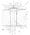
- the figure shows a longitudinal sectional view of a lighting module 10 in a sectioned wall 11 of a test chamber that is not shown in detail here.
- the wall 11 delimits a test space 12 and seals it off from an environment 13.
- the wall 11 is made of metal sheets 14 and 15 that are arranged essentially parallel to one another and that form an intermediate space 16 that is filled with an insulating material 17 for temperature insulation.
- a through hole 18 is formed in the wall 11, into which the lighting module 10 is inserted.
- the lighting module 10 comprises a socket 19 with a light source 21 designed as a light-emitting diode 20, a wall feedthrough 22 and a light guide device 23.
- the wall feedthrough 22 runs from an inner side 24 to an outer side 25 of the wall 11.
- a flange 28 is formed on the inner side 24 or an inner end 26 of a tube 27 of the wall feedthrough 22, which flange lies tightly against the inner side 24.
- An annular flange 30 of the wall duct 22 is attached to the outside 25 at an external end 29 of the wall duct 22.
- the wall duct 22 can be adapted to a thickness of the wall 11 in that the pipe 27 can be moved telescopically within the flange 30.
- the pipe 27 can be connected to the flange 30 by a thread (not shown here), by stretching and/or an adhesive connection.
- the light guide device 23 is arranged within the wall feedthrough 22 and is formed here by a glass rod 31.
- the glass rod 31 is arranged coaxially in the direction of a longitudinal axis 32 of the lighting module 10 relative to the tube 27 or the flange 30 and forms a light exit surface 33 and a light entry surface 34.
- the lighting module 10 also has a sealing device 35 which is designed as a plug 36.
- the glass rod 31 passes through the plug 36 so that the light exit surface 33 is located at the inner end 26 in the test chamber 12.
- the glass rod 31 is also held in the wall feedthrough 22 by circular disks 37 and 38. A gap 39 is thus formed between the wall feedthrough 22 and the glass rod 31.
- the socket 19 is arranged on the outside end 29 and accommodates the LED 20.
- Cooling fins 40 of a cooling device 41 of the socket 19 are formed on the socket 19 and cables 42 are led to the LED 20.
- Light emitted by the LED 20 enters the light entry surface 34 of the glass rod 31 and exits from the light exit surface 33 into the test chamber 12, so that the test chamber 12 is illuminated. Heat emitted by the LED 20 can be emitted to the environment 13 via the cooling device 41. Because the LED 20 is far away from the test chamber 12 via the glass rod 31, and because of the gap 39 and the insulation material 17, the LED 20 is not significantly influenced by the temperatures and ambient conditions prevailing in the test chamber 12, it is not even possible to possible to use the light-emitting diode 20 with a comparatively long service life.
Landscapes
- Physics & Mathematics (AREA)
- General Physics & Mathematics (AREA)
- Life Sciences & Earth Sciences (AREA)
- Health & Medical Sciences (AREA)
- Chemical & Material Sciences (AREA)
- General Engineering & Computer Science (AREA)
- Engineering & Computer Science (AREA)
- Biochemistry (AREA)
- General Health & Medical Sciences (AREA)
- Pathology (AREA)
- Analytical Chemistry (AREA)
- Immunology (AREA)
- Ecology (AREA)
- Environmental Sciences (AREA)
- Environmental & Geological Engineering (AREA)
- Biodiversity & Conservation Biology (AREA)
- Clinical Laboratory Science (AREA)
- Chemical Kinetics & Catalysis (AREA)
- Optics & Photonics (AREA)
- Testing Resistance To Weather, Investigating Materials By Mechanical Methods (AREA)
- Arrangement Of Elements, Cooling, Sealing, Or The Like Of Lighting Devices (AREA)
Claims (11)
- Chambre d'essai pour le conditionnement de l'air, la chambre d'essai comprenant un espace d'essai (12) isolé de la température et pouvant être scellé contre un environnement (13) destiné à recevoir du matériel d'essai, une température allant de -20 °C à +100 °C, de préférence de -60 °C à +180 °C, de préférence encore de -80 °C à +300 °C, pouvant être produite dans l'espace d'essai, le module d'illumination pouvant être disposé au moins partiellement dans l'espace d'essai et l'espace d'essai pouvant être illuminé par le module d'illumination, le module d'illumination comprenant un agent lumineux (21) et une douille (19),
caractérisé en ce que
le module d'illumination comprend un passage de paroi (22) constitué d'un tuyau (27) et d'un autre tuyau ou d'un flasque (30) et un dispositif de conduit de lumière (23), l'autre tuyau ou le flasque étant relié au tuyau et étant conçu à la manière d'un guide de télescope sur le tuyau de manière à pouvoir être déplaçable, le passage de paroi étant disposé dans une paroi (11) entourant l'espace d'essai, le passage de paroi s'étendant d'un côté intérieur (24) à un côté extérieur (25) de la paroi, le dispositif de conduit de lumière ayant une zone de sortie de lumière (33) et une zone d'entrée de lumière (34) et étant disposé dans le passage de paroi où il s'étend d'une extrémité intérieure (26) à une extrémité extérieure (29) du passage de paroi, la douille étant disposée à l'extrémité extérieure et positionnant l'agent lumineux à la zone d'entrée de lumière, la zone de sortie de lumière étant disposée à l'extrémité intérieure, une fente (39) étant formée entre le passage de paroi et le dispositif de conduit de lumière, le module d'illumination (10) comprenant un dispositif d'étanchéité (35) conçu à la manière d'un bouchon (36) qui est inséré dans le passage de paroi à l'extrémité intérieure (26), le dispositif de conduit de lumière étant inséré de telle manière dans le bouchon via un perçage que le dispositif de conduit de lumière traverse le dispositif d'étanchéité et que le dispositif d'étanchéité scelle le dispositif de conduit de lumière au niveau du passage de paroi. - Chambre d'essai selon la revendication 1,
caractérisé en ce que
le dispositif de conduit de lumière (23) est en forme de tige au moins en sections, le dispositif de conduit de lumière étant constitué de verre, de préférence de verre borosilicaté. - Chambre d'essai selon la revendication 1 ou la revendication 2, caractérisé en ce que
le passage de paroi (22) et le dispositif de conduit de lumière (23) sont coaxiaux l'un par rapport à l'autre. - Chambre d'essai selon l'une quelconque des revendications précédentes,
caractérisé en ce que
l'agent lumineux (21) est une diode électroluminescente (20) ou une lampe halogène. - Chambre d'essai selon l'une quelconque des revendications précédentes,
caractérisé en ce que
la douille (19) a un dispositif de refroidissement (41) et des moyens de connexion électriques (42). - Chambre d'essai selon l'une quelconque des revendications précédentes,
caractérisé en ce que
la chambre d'essai comprend des parois (11) isolées thermiquement limitant l'espace d'essai (12), un matériau d'isolation thermique (17) étant disposé entre un côté intérieur (24) et un côté extérieur (25) de la paroi. - Chambre d'essai selon l'une quelconque des revendications précédentes,
caractérisé en ce que
la chambre d'essai comprend un dispositif de régulation de la température de l'espace d'essai (12), une température allant de -20 °C à +100 °C, de préférence de -60 °C à +180 °C, de préférence encore de -80 °C à +300 °C, pouvant être produite à l'intérieur de l'espace d'essai au moyen du dispositif de régulation de la température. - Chambre d'essai selon la revendication 7,
caractérisé en ce que
le dispositif de régulation de la température comprend un dispositif de refroidissement ayant un réfrigérant, un compresseur, un condenseur et un soupape de détente dans un circuit ayant un premier échangeur de chaleur disposé dans l'espace d'essai (12), le réfrigérant pouvant être fourni au premier échangeur de chaleur, le dispositif de régulation de la température comprenant un dispositif de chauffage ayant un chauffage et un deuxième échangeur de chaleur disposé dans l'espace d'essai. - Chambre d'essai selon l'une quelconque des revendications précédentes,
caractérisé en ce
qu'un côté intérieur de la paroi de l'espace d'essai (12) est conçu pour résister à un fluide corrosif. - Chambre d'essai selon l'une quelconque des revendications précédentes,
caractérisé en ce que
la chambre d'essai comprend un dispositif de contrôle pour établir une condition d'essai en contrôlant et/ou en régulant une température de l'air, une pression de l'air et une humidité relative de l'air dans l'espace d'essai (12). - Procédé de modification d'une chambre d'essai ayant un espace d'essai (12) isolé de la température et pouvant être scellé contre un environnement (13) destiné à recevoir du matériel d'essai, une température allant de -20 °C à +100 °C, de préférence de -60 °C à +180 °C, de préférence encore de -80 °C à +300 °C, pouvant être produite à l'intérieur de l'espace d'essai, une lampe dont le boîtier est disposé à l'intérieur de l'espace d'essai sur un côté intérieur (24) d'une paroi (11) isolée thermiquement de la chambre d'essai, qui entoure l'espace d'essai, étant enlevée, un perçage traversant (18) étant formé entre un côté extérieur (25) de la paroi et le côté intérieur, un module d'illumination (10) comprenant un passage de paroi (22), formé par un tuyau (27) et un autre tuyau ou flasque (30), un dispositif de conduit de lumière (23), un agent lumineux (21) et une douille (19) étant inséré dans le perçage traversant de telle sorte que le passage de paroi s'étende du côté intérieur au côté extérieur de la paroi, l'autre tuyau ou la flasque étant conçu de manière à pouvoir être déplaçables à la manière d'un guide de télescope sur le tuyau et étant reliés au tuyau, le dispositif de conduit de lumière ayant une zone de sortie de lumière (33) et une zone d'entrée de lumière (34) et étant disposé à l'intérieur du passage de paroi par lequel il s'étend d'une extrémité intérieure (26) à une extrémité extérieure (29) du passage de paroi, la douille étant disposée à l'extrémité extérieure et positionnant l'agent lumineux à la zone d'entrée de lumière, la zone de sortie de lumière étant disposée à l'extrémité intérieure, une fente (39) étant formée entre le passage de paroi et le dispositif de conduit de lumière, le module d'illumination comprenant un dispositif d'étanchéité (35) conçu à la manière d'un bouchon (36) qui est inséré dans le passage de paroi à l'extrémité intérieure, le dispositif de conduit de lumière étant inséré de telle manière dans le bouchon via un perçage que le dispositif de conduit de lumière traverse le dispositif d'étanchéité et que le dispositif d'étanchéité scelle le dispositif de conduit de lumière au niveau du passage de paroi.
Priority Applications (5)
| Application Number | Priority Date | Filing Date | Title |
|---|---|---|---|
| EP19177697.0A EP3744428B1 (fr) | 2019-05-31 | 2019-05-31 | Chambre d'essai |
| KR1020200057984A KR20200137995A (ko) | 2019-05-31 | 2020-05-14 | 조명 디바이스 및 테스트 챔버 |
| JP2020084877A JP7563894B2 (ja) | 2019-05-31 | 2020-05-14 | 試験室 |
| CN202010460918.XA CN112013298A (zh) | 2019-05-31 | 2020-05-27 | 照明装置和测试腔 |
| US16/887,176 US11506722B2 (en) | 2019-05-31 | 2020-05-29 | Illumination device and test chamber |
Applications Claiming Priority (1)
| Application Number | Priority Date | Filing Date | Title |
|---|---|---|---|
| EP19177697.0A EP3744428B1 (fr) | 2019-05-31 | 2019-05-31 | Chambre d'essai |
Publications (2)
| Publication Number | Publication Date |
|---|---|
| EP3744428A1 EP3744428A1 (fr) | 2020-12-02 |
| EP3744428B1 true EP3744428B1 (fr) | 2024-11-06 |
Family
ID=66751905
Family Applications (1)
| Application Number | Title | Priority Date | Filing Date |
|---|---|---|---|
| EP19177697.0A Active EP3744428B1 (fr) | 2019-05-31 | 2019-05-31 | Chambre d'essai |
Country Status (5)
| Country | Link |
|---|---|
| US (1) | US11506722B2 (fr) |
| EP (1) | EP3744428B1 (fr) |
| JP (1) | JP7563894B2 (fr) |
| KR (1) | KR20200137995A (fr) |
| CN (1) | CN112013298A (fr) |
Families Citing this family (2)
| Publication number | Priority date | Publication date | Assignee | Title |
|---|---|---|---|---|
| CN113759196B (zh) * | 2021-09-08 | 2022-09-13 | 山东大学 | 一种高压电气设备实验装置及其实验方法 |
| DE102022115272A1 (de) | 2022-06-20 | 2023-12-21 | Schott Ag | Sensorkopf für Fluoreszenzspektroskopie |
Citations (1)
| Publication number | Priority date | Publication date | Assignee | Title |
|---|---|---|---|---|
| WO2017157864A1 (fr) * | 2016-03-16 | 2017-09-21 | Weiss Umwelttechnik Gmbh | Chambre d'essai |
Family Cites Families (19)
| Publication number | Priority date | Publication date | Assignee | Title |
|---|---|---|---|---|
| US3813514A (en) * | 1972-10-16 | 1974-05-28 | J Canty | Light piping unit for supplying radiant energy to the interior of a pressure vessel |
| US3984673A (en) * | 1975-06-30 | 1976-10-05 | The United States Of America As Represented By The Secretary Of The Navy | External lighting system for hypobaric and hyperbaric chambers |
| LU87151A1 (de) * | 1988-03-04 | 1989-10-26 | Euratom | Beleuchtungsvorrichtung fuer geschlossene raeume |
| EP0446692A1 (fr) * | 1990-03-15 | 1991-09-18 | Eta Ingenieurgesellschaft Für Energietechnik Und Energieanwendung Mbh | Dispositif d'éclairage avec guides de lumière, en particulier pour chambre froide et chambre antidéflagrante |
| SE9701798L (sv) * | 1997-05-15 | 1998-11-16 | Celsiustech Electronics Ab | Belysningsanordning samt förfarande för montering av belysningsanordningen |
| JP2004093623A (ja) * | 2002-08-29 | 2004-03-25 | Olympus Corp | 照明装置及びそれを用いた表示装置 |
| DE10248899A1 (de) * | 2002-10-18 | 2004-05-06 | Weiss Umwelttechnik Gmbh | Prüfschrank |
| US6984058B2 (en) * | 2003-06-04 | 2006-01-10 | 3M Innovative Properties Company | Optical filters comprising opacified portion |
| DE202004000542U1 (de) * | 2004-01-15 | 2004-04-15 | Storz Endoskop Produktions Gmbh | Beleuchtungseinrichtung für ein endoskopisches System zur Inspektion eines Hohlraumes sowie derartiges endoskopisches System |
| US7458708B2 (en) * | 2006-08-09 | 2008-12-02 | Chen Keng Sheng | Lighting fixture |
| JP4640678B2 (ja) * | 2007-03-12 | 2011-03-02 | 清水建設株式会社 | 照明器具の設置構造 |
| KR100874760B1 (ko) * | 2007-07-06 | 2008-12-19 | 한국원자력연구원 | 핫셀 내의 조명기기 |
| US7874690B2 (en) * | 2008-06-24 | 2011-01-25 | Tyco Electronics Corporation | LED lighting fixture for illuminating a cavity |
| CH701962B1 (de) * | 2009-10-05 | 2014-02-14 | Staub Designlight Ag | Beleuchtungseinrichtung und Lampe für diese. |
| CN104048284B (zh) * | 2014-06-13 | 2016-04-06 | 江苏东九重工股份有限公司 | 高温固体热量回收余热锅炉及回收余热的方法 |
| WO2016089726A1 (fr) * | 2014-12-02 | 2016-06-09 | Innovations In Optics, Inc. | Moteur de lumière à diodes électroluminescentes à rayonnement élevé |
| CN205808550U (zh) * | 2016-06-06 | 2016-12-14 | 深圳市普盛旺科技有限公司 | 光照性能自动测试机 |
| EP3404421B1 (fr) * | 2017-05-15 | 2024-09-25 | Eppendorf SE | Instrument de laboratoire et instrument de réseau insérable |
| JP6913593B2 (ja) * | 2017-09-29 | 2021-08-04 | エスペック株式会社 | 環境形成装置及び窓部構造 |
-
2019
- 2019-05-31 EP EP19177697.0A patent/EP3744428B1/fr active Active
-
2020
- 2020-05-14 KR KR1020200057984A patent/KR20200137995A/ko not_active Withdrawn
- 2020-05-14 JP JP2020084877A patent/JP7563894B2/ja active Active
- 2020-05-27 CN CN202010460918.XA patent/CN112013298A/zh active Pending
- 2020-05-29 US US16/887,176 patent/US11506722B2/en active Active
Patent Citations (1)
| Publication number | Priority date | Publication date | Assignee | Title |
|---|---|---|---|---|
| WO2017157864A1 (fr) * | 2016-03-16 | 2017-09-21 | Weiss Umwelttechnik Gmbh | Chambre d'essai |
Non-Patent Citations (1)
| Title |
|---|
| SAXE STEVEN G: "Solar Energy Materials 19 (1989) 95-109 95 North-Holland, Amsterdam PRISMATIC FILM LIGHT GUIDES: PERFORMANCE AND RECENT DEVELOPMENTS", SOLAR ENERGY MATERIALS, vol. 19, 1 January 1989 (1989-01-01), pages 95 - 109, XP093102992, Retrieved from the Internet <URL:https://pdf.sciencedirectassets.com/272839/1-s2.0-S0165163300X00251/1-s2.0-0165163389900269/main.pdf?X-Amz-Security-Token=IQoJb3JpZ2luX2VjEF4aCXVzLWVhc3QtMSJHMEUCIQCtPH0j5go1kluS6yWZ/8jHFbJ2LScha56NiVDefdmA/gIgcXLdbnHRZlEIx/b+qHkBVLzRiVT6rxC3VoupJw22uOwquwUIp///////////ARAFGgwwNTkwMDM1NDY4NjUiDNYGay> * |
Also Published As
| Publication number | Publication date |
|---|---|
| EP3744428A1 (fr) | 2020-12-02 |
| JP7563894B2 (ja) | 2024-10-08 |
| US11506722B2 (en) | 2022-11-22 |
| US20200379053A1 (en) | 2020-12-03 |
| CN112013298A (zh) | 2020-12-01 |
| JP2020198299A (ja) | 2020-12-10 |
| KR20200137995A (ko) | 2020-12-09 |
Similar Documents
| Publication | Publication Date | Title |
|---|---|---|
| EP2251588B1 (fr) | Lampe pour appareil ménager et appareil ménager, notamment pour la préparation d'aliments, doté d'une lampe | |
| EP3744428B1 (fr) | Chambre d'essai | |
| DE112010005450T5 (de) | Beleuchtungsanordnungen mit einer gesteuerten, gerichteten Wärmeübertragung | |
| DE202011050563U1 (de) | LED-Leuchte | |
| DE102011015161A1 (de) | LED-Beleuchtungseinrichtung | |
| EP0446692A1 (fr) | Dispositif d'éclairage avec guides de lumière, en particulier pour chambre froide et chambre antidéflagrante | |
| DE102009042615B4 (de) | Anschlusselement zur elektrischen Anbindung einer LED | |
| DE4404247A1 (de) | Beleuchtungssystem für die Innenbeleuchtung von Kühlmöbeln, Vitrinen und dergleichen | |
| DE102016113617A1 (de) | Ofenleuchte | |
| WO2010076121A1 (fr) | Système d'éclairage à base de diodes del | |
| WO2011006178A1 (fr) | Luminaire électrique | |
| AT509626B1 (de) | Modulares led beleuchtungssystem mit partieller lichtstärkenanpassung | |
| DE102013108248A1 (de) | Beleuchtungssystem, insbesondere für einen Kraftfahrzeugscheinwerfer mit einem Kühlkörper | |
| DE102012012853A1 (de) | Lampe mit einem zentralen Gewinde und seitlich zur Längsachse des Gewindes strahlendem Licht, dessen Richtung um diese Achse verstellbar ist. | |
| DE102006041959A1 (de) | Beleuchtungssystem zum Erzeugen von Licht und zum Einkoppeln des Lichts in ein proximales Ende eines Lichtleitkabels einer Beobachtungsvorrichtung für die Endoskopie oder Mikroskopie | |
| DE202009014794U1 (de) | Beleuchtungseinrichtung und Lampe für diese | |
| DE202012008928U1 (de) | Beleuchtungsvorrichtung | |
| CH701962B1 (de) | Beleuchtungseinrichtung und Lampe für diese. | |
| DE102011012132B3 (de) | Unterwasserscheinwerfer | |
| DE202010013103U1 (de) | Hinterleuchteter Heizkörper | |
| DE102010027697A1 (de) | Modulare LED-Beleuchtungseinrichtung | |
| DE102014009628A1 (de) | Außenleuchte für ein Fahrzeug | |
| DE202015106203U1 (de) | Leuchte | |
| DE102007037190A1 (de) | Hochleistungs-LED-Lampe | |
| DE202006013696U1 (de) | Beleuchtungssystem zum Erzeugen von Licht und zum Einkoppeln des Lichts in ein proximales Ende eines Lichtleitkabels einer Beobachtungsvorrichtung für die Endoskopie oder Mikroskopie |
Legal Events
| Date | Code | Title | Description |
|---|---|---|---|
| PUAI | Public reference made under article 153(3) epc to a published international application that has entered the european phase |
Free format text: ORIGINAL CODE: 0009012 |
|
| STAA | Information on the status of an ep patent application or granted ep patent |
Free format text: STATUS: THE APPLICATION HAS BEEN PUBLISHED |
|
| AK | Designated contracting states |
Kind code of ref document: A1 Designated state(s): AL AT BE BG CH CY CZ DE DK EE ES FI FR GB GR HR HU IE IS IT LI LT LU LV MC MK MT NL NO PL PT RO RS SE SI SK SM TR |
|
| AX | Request for extension of the european patent |
Extension state: BA ME |
|
| STAA | Information on the status of an ep patent application or granted ep patent |
Free format text: STATUS: REQUEST FOR EXAMINATION WAS MADE |
|
| 17P | Request for examination filed |
Effective date: 20210531 |
|
| RBV | Designated contracting states (corrected) |
Designated state(s): AL AT BE BG CH CY CZ DE DK EE ES FI FR GB GR HR HU IE IS IT LI LT LU LV MC MK MT NL NO PL PT RO RS SE SI SK SM TR |
|
| STAA | Information on the status of an ep patent application or granted ep patent |
Free format text: STATUS: EXAMINATION IS IN PROGRESS |
|
| 17Q | First examination report despatched |
Effective date: 20221006 |
|
| GRAP | Despatch of communication of intention to grant a patent |
Free format text: ORIGINAL CODE: EPIDOSNIGR1 |
|
| STAA | Information on the status of an ep patent application or granted ep patent |
Free format text: STATUS: GRANT OF PATENT IS INTENDED |
|
| RIC1 | Information provided on ipc code assigned before grant |
Ipc: F21W 131/411 20060101ALN20240517BHEP Ipc: F21S 8/02 20060101ALI20240517BHEP Ipc: F21V 33/00 20060101ALI20240517BHEP Ipc: G02B 6/42 20060101ALI20240517BHEP Ipc: F21V 8/00 20060101ALI20240517BHEP Ipc: G01N 17/00 20060101ALI20240517BHEP Ipc: B01L 1/02 20060101AFI20240517BHEP |
|
| INTG | Intention to grant announced |
Effective date: 20240605 |
|
| GRAS | Grant fee paid |
Free format text: ORIGINAL CODE: EPIDOSNIGR3 |
|
| GRAA | (expected) grant |
Free format text: ORIGINAL CODE: 0009210 |
|
| STAA | Information on the status of an ep patent application or granted ep patent |
Free format text: STATUS: THE PATENT HAS BEEN GRANTED |
|
| RAP3 | Party data changed (applicant data changed or rights of an application transferred) |
Owner name: CLIMATS S.A.S. Owner name: WEISS TECHNIK GMBH |
|
| RIN1 | Information on inventor provided before grant (corrected) |
Inventor name: DIETZ, RICARDO Inventor name: REUSCHEL, DENNIS Inventor name: SCHLOSSER, VOLKER Inventor name: HAACK, CHRISTIAN Inventor name: EMON, MATTHIAS |
|
| AK | Designated contracting states |
Kind code of ref document: B1 Designated state(s): AL AT BE BG CH CY CZ DE DK EE ES FI FR GB GR HR HU IE IS IT LI LT LU LV MC MK MT NL NO PL PT RO RS SE SI SK SM TR |
|
| REG | Reference to a national code |
Ref country code: GB Ref legal event code: FG4D Free format text: NOT ENGLISH |
|
| REG | Reference to a national code |
Ref country code: CH Ref legal event code: EP |
|
| REG | Reference to a national code |
Ref country code: DE Ref legal event code: R096 Ref document number: 502019012421 Country of ref document: DE |
|
| REG | Reference to a national code |
Ref country code: IE Ref legal event code: FG4D Free format text: LANGUAGE OF EP DOCUMENT: GERMAN |
|
| P01 | Opt-out of the competence of the unified patent court (upc) registered |
Free format text: CASE NUMBER: APP_62012/2024 Effective date: 20241120 |
|
| RAP2 | Party data changed (patent owner data changed or rights of a patent transferred) |
Owner name: WEISS TECHNIK FRANCE S.A.S. Owner name: WEISS TECHNIK GMBH |
|
| REG | Reference to a national code |
Ref country code: LT Ref legal event code: MG9D |
|
| REG | Reference to a national code |
Ref country code: NL Ref legal event code: MP Effective date: 20241106 |
|
| PG25 | Lapsed in a contracting state [announced via postgrant information from national office to epo] |
Ref country code: HR Free format text: LAPSE BECAUSE OF FAILURE TO SUBMIT A TRANSLATION OF THE DESCRIPTION OR TO PAY THE FEE WITHIN THE PRESCRIBED TIME-LIMIT Effective date: 20241106 Ref country code: PT Free format text: LAPSE BECAUSE OF FAILURE TO SUBMIT A TRANSLATION OF THE DESCRIPTION OR TO PAY THE FEE WITHIN THE PRESCRIBED TIME-LIMIT Effective date: 20250306 Ref country code: IS Free format text: LAPSE BECAUSE OF FAILURE TO SUBMIT A TRANSLATION OF THE DESCRIPTION OR TO PAY THE FEE WITHIN THE PRESCRIBED TIME-LIMIT Effective date: 20250306 |
|
| PG25 | Lapsed in a contracting state [announced via postgrant information from national office to epo] |
Ref country code: FI Free format text: LAPSE BECAUSE OF FAILURE TO SUBMIT A TRANSLATION OF THE DESCRIPTION OR TO PAY THE FEE WITHIN THE PRESCRIBED TIME-LIMIT Effective date: 20241106 Ref country code: NL Free format text: LAPSE BECAUSE OF FAILURE TO SUBMIT A TRANSLATION OF THE DESCRIPTION OR TO PAY THE FEE WITHIN THE PRESCRIBED TIME-LIMIT Effective date: 20241106 |
|
| PG25 | Lapsed in a contracting state [announced via postgrant information from national office to epo] |
Ref country code: BG Free format text: LAPSE BECAUSE OF FAILURE TO SUBMIT A TRANSLATION OF THE DESCRIPTION OR TO PAY THE FEE WITHIN THE PRESCRIBED TIME-LIMIT Effective date: 20241106 |
|
| PG25 | Lapsed in a contracting state [announced via postgrant information from national office to epo] |
Ref country code: ES Free format text: LAPSE BECAUSE OF FAILURE TO SUBMIT A TRANSLATION OF THE DESCRIPTION OR TO PAY THE FEE WITHIN THE PRESCRIBED TIME-LIMIT Effective date: 20241106 |
|
| PG25 | Lapsed in a contracting state [announced via postgrant information from national office to epo] |
Ref country code: NO Free format text: LAPSE BECAUSE OF FAILURE TO SUBMIT A TRANSLATION OF THE DESCRIPTION OR TO PAY THE FEE WITHIN THE PRESCRIBED TIME-LIMIT Effective date: 20250206 |
|
| PG25 | Lapsed in a contracting state [announced via postgrant information from national office to epo] |
Ref country code: LV Free format text: LAPSE BECAUSE OF FAILURE TO SUBMIT A TRANSLATION OF THE DESCRIPTION OR TO PAY THE FEE WITHIN THE PRESCRIBED TIME-LIMIT Effective date: 20241106 Ref country code: GR Free format text: LAPSE BECAUSE OF FAILURE TO SUBMIT A TRANSLATION OF THE DESCRIPTION OR TO PAY THE FEE WITHIN THE PRESCRIBED TIME-LIMIT Effective date: 20250207 |
|
| PG25 | Lapsed in a contracting state [announced via postgrant information from national office to epo] |
Ref country code: PL Free format text: LAPSE BECAUSE OF FAILURE TO SUBMIT A TRANSLATION OF THE DESCRIPTION OR TO PAY THE FEE WITHIN THE PRESCRIBED TIME-LIMIT Effective date: 20241106 |
|
| PG25 | Lapsed in a contracting state [announced via postgrant information from national office to epo] |
Ref country code: RS Free format text: LAPSE BECAUSE OF FAILURE TO SUBMIT A TRANSLATION OF THE DESCRIPTION OR TO PAY THE FEE WITHIN THE PRESCRIBED TIME-LIMIT Effective date: 20250206 |
|
| PG25 | Lapsed in a contracting state [announced via postgrant information from national office to epo] |
Ref country code: SM Free format text: LAPSE BECAUSE OF FAILURE TO SUBMIT A TRANSLATION OF THE DESCRIPTION OR TO PAY THE FEE WITHIN THE PRESCRIBED TIME-LIMIT Effective date: 20241106 |
|
| PGFP | Annual fee paid to national office [announced via postgrant information from national office to epo] |
Ref country code: DE Payment date: 20250528 Year of fee payment: 7 |
|
| PG25 | Lapsed in a contracting state [announced via postgrant information from national office to epo] |
Ref country code: DK Free format text: LAPSE BECAUSE OF FAILURE TO SUBMIT A TRANSLATION OF THE DESCRIPTION OR TO PAY THE FEE WITHIN THE PRESCRIBED TIME-LIMIT Effective date: 20241106 |
|
| PGFP | Annual fee paid to national office [announced via postgrant information from national office to epo] |
Ref country code: GB Payment date: 20250520 Year of fee payment: 7 |
|
| PGFP | Annual fee paid to national office [announced via postgrant information from national office to epo] |
Ref country code: IT Payment date: 20250522 Year of fee payment: 7 |
|
| PG25 | Lapsed in a contracting state [announced via postgrant information from national office to epo] |
Ref country code: EE Free format text: LAPSE BECAUSE OF FAILURE TO SUBMIT A TRANSLATION OF THE DESCRIPTION OR TO PAY THE FEE WITHIN THE PRESCRIBED TIME-LIMIT Effective date: 20241106 |
|
| PGFP | Annual fee paid to national office [announced via postgrant information from national office to epo] |
Ref country code: FR Payment date: 20250526 Year of fee payment: 7 |
|
| PG25 | Lapsed in a contracting state [announced via postgrant information from national office to epo] |
Ref country code: RO Free format text: LAPSE BECAUSE OF FAILURE TO SUBMIT A TRANSLATION OF THE DESCRIPTION OR TO PAY THE FEE WITHIN THE PRESCRIBED TIME-LIMIT Effective date: 20241106 |
|
| PG25 | Lapsed in a contracting state [announced via postgrant information from national office to epo] |
Ref country code: SK Free format text: LAPSE BECAUSE OF FAILURE TO SUBMIT A TRANSLATION OF THE DESCRIPTION OR TO PAY THE FEE WITHIN THE PRESCRIBED TIME-LIMIT Effective date: 20241106 |
|
| PG25 | Lapsed in a contracting state [announced via postgrant information from national office to epo] |
Ref country code: CZ Free format text: LAPSE BECAUSE OF FAILURE TO SUBMIT A TRANSLATION OF THE DESCRIPTION OR TO PAY THE FEE WITHIN THE PRESCRIBED TIME-LIMIT Effective date: 20241106 |
|
| REG | Reference to a national code |
Ref country code: DE Ref legal event code: R097 Ref document number: 502019012421 Country of ref document: DE |
|
| PG25 | Lapsed in a contracting state [announced via postgrant information from national office to epo] |
Ref country code: SE Free format text: LAPSE BECAUSE OF FAILURE TO SUBMIT A TRANSLATION OF THE DESCRIPTION OR TO PAY THE FEE WITHIN THE PRESCRIBED TIME-LIMIT Effective date: 20241106 |
|
| PLBE | No opposition filed within time limit |
Free format text: ORIGINAL CODE: 0009261 |
|
| STAA | Information on the status of an ep patent application or granted ep patent |
Free format text: STATUS: NO OPPOSITION FILED WITHIN TIME LIMIT |
|
| 26N | No opposition filed |
Effective date: 20250807 |
|
| REG | Reference to a national code |
Ref country code: CH Ref legal event code: H13 Free format text: ST27 STATUS EVENT CODE: U-0-0-H10-H13 (AS PROVIDED BY THE NATIONAL OFFICE) Effective date: 20251223 |
|
| PG25 | Lapsed in a contracting state [announced via postgrant information from national office to epo] |
Ref country code: LU Free format text: LAPSE BECAUSE OF NON-PAYMENT OF DUE FEES Effective date: 20250531 |
|
| PG25 | Lapsed in a contracting state [announced via postgrant information from national office to epo] |
Ref country code: CH Free format text: LAPSE BECAUSE OF NON-PAYMENT OF DUE FEES Effective date: 20250531 |
|
| REG | Reference to a national code |
Ref country code: BE Ref legal event code: MM Effective date: 20250531 |
|
| PG25 | Lapsed in a contracting state [announced via postgrant information from national office to epo] |
Ref country code: MC Free format text: LAPSE BECAUSE OF FAILURE TO SUBMIT A TRANSLATION OF THE DESCRIPTION OR TO PAY THE FEE WITHIN THE PRESCRIBED TIME-LIMIT Effective date: 20241106 |
|
| PG25 | Lapsed in a contracting state [announced via postgrant information from national office to epo] |
Ref country code: IE Free format text: LAPSE BECAUSE OF NON-PAYMENT OF DUE FEES Effective date: 20250531 |
|
| PG25 | Lapsed in a contracting state [announced via postgrant information from national office to epo] |
Ref country code: BE Free format text: LAPSE BECAUSE OF NON-PAYMENT OF DUE FEES Effective date: 20250531 |