EP3744437A1 - Biegevorrichtung - Google Patents
Biegevorrichtung Download PDFInfo
- Publication number
- EP3744437A1 EP3744437A1 EP18910850.9A EP18910850A EP3744437A1 EP 3744437 A1 EP3744437 A1 EP 3744437A1 EP 18910850 A EP18910850 A EP 18910850A EP 3744437 A1 EP3744437 A1 EP 3744437A1
- Authority
- EP
- European Patent Office
- Prior art keywords
- bending
- workpiece
- pair
- punch
- support member
- Prior art date
- Legal status (The legal status is an assumption and is not a legal conclusion. Google has not performed a legal analysis and makes no representation as to the accuracy of the status listed.)
- Withdrawn
Links
- 238000005452 bending Methods 0.000 title claims abstract description 94
- 238000003825 pressing Methods 0.000 claims abstract description 15
- 239000011435 rock Substances 0.000 description 16
- 229910052751 metal Inorganic materials 0.000 description 13
- 239000002184 metal Substances 0.000 description 13
- 238000013459 approach Methods 0.000 description 4
- 230000003247 decreasing effect Effects 0.000 description 4
- 238000004519 manufacturing process Methods 0.000 description 4
- 239000000463 material Substances 0.000 description 3
- 230000004048 modification Effects 0.000 description 3
- 238000012986 modification Methods 0.000 description 3
- 238000005299 abrasion Methods 0.000 description 2
- 238000000034 method Methods 0.000 description 2
- 229910000831 Steel Inorganic materials 0.000 description 1
- 229910052782 aluminium Inorganic materials 0.000 description 1
- XAGFODPZIPBFFR-UHFFFAOYSA-N aluminium Chemical compound [Al] XAGFODPZIPBFFR-UHFFFAOYSA-N 0.000 description 1
- 238000010586 diagram Methods 0.000 description 1
- 239000013013 elastic material Substances 0.000 description 1
- 208000037805 labour Diseases 0.000 description 1
- 229910001220 stainless steel Inorganic materials 0.000 description 1
- 239000010935 stainless steel Substances 0.000 description 1
- 239000010959 steel Substances 0.000 description 1
Images



Classifications
-
- B—PERFORMING OPERATIONS; TRANSPORTING
- B21—MECHANICAL METAL-WORKING WITHOUT ESSENTIALLY REMOVING MATERIAL; PUNCHING METAL
- B21D—WORKING OR PROCESSING OF SHEET METAL OR METAL TUBES, RODS OR PROFILES WITHOUT ESSENTIALLY REMOVING MATERIAL; PUNCHING METAL
- B21D5/00—Bending sheet metal along straight lines, e.g. to form simple curves
- B21D5/01—Bending sheet metal along straight lines, e.g. to form simple curves between rams and anvils or abutments
-
- B—PERFORMING OPERATIONS; TRANSPORTING
- B21—MECHANICAL METAL-WORKING WITHOUT ESSENTIALLY REMOVING MATERIAL; PUNCHING METAL
- B21D—WORKING OR PROCESSING OF SHEET METAL OR METAL TUBES, RODS OR PROFILES WITHOUT ESSENTIALLY REMOVING MATERIAL; PUNCHING METAL
- B21D5/00—Bending sheet metal along straight lines, e.g. to form simple curves
- B21D5/02—Bending sheet metal along straight lines, e.g. to form simple curves on press brakes without making use of clamping means
- B21D5/0209—Tools therefor
- B21D5/0263—Die with two oscillating halves
-
- B—PERFORMING OPERATIONS; TRANSPORTING
- B21—MECHANICAL METAL-WORKING WITHOUT ESSENTIALLY REMOVING MATERIAL; PUNCHING METAL
- B21D—WORKING OR PROCESSING OF SHEET METAL OR METAL TUBES, RODS OR PROFILES WITHOUT ESSENTIALLY REMOVING MATERIAL; PUNCHING METAL
- B21D5/00—Bending sheet metal along straight lines, e.g. to form simple curves
- B21D5/02—Bending sheet metal along straight lines, e.g. to form simple curves on press brakes without making use of clamping means
- B21D5/0209—Tools therefor
-
- B—PERFORMING OPERATIONS; TRANSPORTING
- B21—MECHANICAL METAL-WORKING WITHOUT ESSENTIALLY REMOVING MATERIAL; PUNCHING METAL
- B21D—WORKING OR PROCESSING OF SHEET METAL OR METAL TUBES, RODS OR PROFILES WITHOUT ESSENTIALLY REMOVING MATERIAL; PUNCHING METAL
- B21D5/00—Bending sheet metal along straight lines, e.g. to form simple curves
- B21D5/02—Bending sheet metal along straight lines, e.g. to form simple curves on press brakes without making use of clamping means
- B21D5/0281—Workpiece supporting devices
Definitions
- the present invention relates to a bending tool, such as a press brake, which is used to bend a plate-shaped workpiece made of sheet metal or the like into a V shape or the like using a die.
- a bending tool such as a press brake
- a die for bending a metal plate including a base, a pair of die members having a reception face for receiving a metal plate and capable of rocking while distal ends of the reception faces are joined to each other, and a synchronization mechanism for synchronizing and rocking the pair of die members, in which a metal plate is placed on the reception plate in a horizontal position of the pair of die members, and a portion to be bent of the metal plate is pressed by a punch, whereby the pair of die members are moved into an inclined position so that the metal plate is bent (e.g. see Patent Literature 1).
- the base is provided with fulcrum portions which serve as a fulcrum on which the pair of die members rock, a slider block for supporting a back face side of the pair of die members, and a slider guide hole for reciprocatably guiding the slider block.
- one projecting portion is provided, with respect to the fulcrum portion of the base, on each of a distal end side and a proximal end side of the die member (four projecting portions in total) .
- the base is provided with two guide recessed portions on each of the distal end side and the proximal end side which correspond to the projecting portion on the distal end side and the projecting portion on the proximal end side, respectively, and slidably guide an outer face of the respective projecting portions (four guide recessed portions in total).
- the synchronization mechanism is configured to include a guide pin provided to project at positions symmetrical to each other on each of both side face sides of the pair of die members, a guide plate provided along side face sides of the base and having a long hole into which the guide pin is inserted, a cover plate on the surface of the guide plate to stop the guide pin, and the like.
- the pair of die members are rocked from the horizontal position where the reception faces form a plane into a predetermined angle inclined position where the reception faces are inclined mirror-symmetrically to each other with respect to a joined line of the distal ends so that the reception faces form an angle.
- the projecting portion on the distal end side approaches the guide recessed portion on the distal end side and the projecting portion on the proximal end side separates from the guide recessed portion on the proximal end side, whereby the die members on the distal end side lowers. Consequently, the slider block descends in the slider guide hole.
- Patent Literature 1 JP2011-206823A
- a bending tool of the present invention includes: a pair of movable dies arranged such that a bending line of a punch and a workpiece is interposed therebetween; a support member for supporting the pair of movable dies in a manner rotatable into directions opposite to each other in accordance with bending of the workpiece by the punch; and a body for supporting the support member in a manner reciprocatable in a movement direction of the punch in accordance with bending of the workpiece by the punch, in which the pair of movable dies have respective reception faces for the workpiece, respective bending side end portions formed on the respective reception faces in such a manner as to face the bending line of the workpiece, and respective convex circular faces formed to face the support member, and the support member has respective concave circular faces which slidably fit respectively with the convex circular faces, while the bending side end portions of the pair of movable dies are joined to or fit with each other in accordance with bending of the workpiece by the
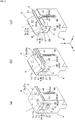
- a bending tool A is a bending press for bending a plate-shaped workpiece W into a V shape or the like in cooperation with a punch P which is an upper die and a pair of movable dies 1, 2 which serve as a lower die.
- the workpiece W for example, a sheet metal of steel, stainless steel, aluminum, etc. or a thin plate similar thereto is used, and both flat plate portions W2, W2 are pushed to be bent (thrusted to be bent), such that a bending line W1 is interposed therebetween, to a certain angle by abutting against a blade portion P1 of the punch P.
- the bending tool A is preferably used to be incorporated in a press brake (unillustrated) or the like.
- a bending angle of the workpiece W is detected during a workpiece W bending process and this bending angle is fed back to a numerical control (NC) wirelessly or wiredly so that the bending angle of the workpiece W can be automatically modified by adjusting a movement amount of the punch P.
- NC numerical control
- the bending tool A includes as main components: a pair of movable dies 1, 2 arranged such that the bending line W1 of the punch P and the workpiece W is interposed therebetween; a support member 3 for supporting the pair of movable dies 1, 2 in a manner rotatable in directions opposite to each other in accordance with bending of the workpiece W by the punch P; and a body 4 for supporting the support member 3 in a manner reciprocatable in a movement direction of the punch P in accordance with bending of the workpiece W by the punch P.
- an elastic member 5 for restoring the pair of movable dies 1, 2 to rotate in directions each opposite to the respective directions of rotation in accordance with bending of the workpiece W by the punch P, and an urging member 6 for urging the support member 3 in a direction opposite to a pressing direction of the workpiece W by the punch P are provided.
- the punch P and the pair of movable dies 1, 2 are typically arranged in such a manner as to face each other in a vertical direction, and the movement direction of the punch P will be hereinafter referred to as "Z direction".
- Z direction A width direction of the pair of movable dies 1, 2 intersecting Z direction will be referred to as "X direction”
- Y direction an arrangement direction (alignment direction) of the pair of movable dies 1, 2 intersecting Z direction
- the pair of movable dies 1, 2 are formed of a hard material, such as metal, and in a belt shape and have respective reception faces 11, 21 which come into contact with both the flat plate portions W2, W2 of the workpiece W placed thereon.
- the reception faces 11, 21 have respective bending side end portions 11a, 21a formed on a front side to face both the flat plate portions W2, W2 of the workpiece W in Z direction and facing the bending line W1 of the workpiece W in Z direction.
- the bending side end portion 11a of the reception face 11 is formed over the entirety of the reception face 11 in X direction.
- the bending side end portion 21a of the reception face 21 is formed over the entirety of the reception face 21 in X direction.
- the pair of movable dies 1, 2 have respective convex circular faces 12, 22 which protrude toward the support member 3 described below, and respective stoppers 13, 23 which abut against a stopping portion 41 of the body 4 described below.
- the convex circular faces 12, 22 and the stoppers 13, 23 are formed in the pair of movable dies 1, 2 on a back side facing the support member 3 and the body 4 described below in Z direction.
- the convex circular faces 12, 22 have a substantially quarter circular side shape as seen from X direction and are formed in a continuous manner in the same shape over the entirety of the pair of movable dies 1, 2 in X direction, respectively.
- the convex circular faces 12, 22 are formed in a substantially quarter circular shape about a rotation fulcrum portions 1o, 2o, respectively, and are configured to have the same size such that respective rotation radii are equal to each other.
- the convex circular faces 12, 22 may be formed in a substantially quarter circular shape such that respective rotation radii are different from each other (have different sizes), and may be modified to a configuration other than that as illustrated in the figures.
- the stopper 13, 23 are configured such that the reception faces 11, 21 are disposed in a horizontal position to form a continuous plane by abutting the stoppers 13, 23 against the stopping portion 41 of the body 4 described below.
- the support member 3 is formed of a hard material, such as metal, and in a prismatic shape, etc. including a square pole and has respective concave circular faces 31, 32 which constantly slidably fit with the convex circular faces 12, 22 of the pair of movable dies 1, 2.
- the concave circular faces 31, 32 have a substantially quarter circular side shape as seen from X direction in such a manner as to slidably fit in a concavo-convex manner with the convex circular faces 12, 22, and are formed in a continuous manner in the same shape over the entirety of the support member 3 in X direction, respectively.
- the convex circular faces 12, 22 are made to slide along the concave circular faces 31, 32, whereby the pair of movable dies 1, 2 as a whole rotate (rock) simultaneously about the rotation fulcrum portions 1o, 2o, respectively, in directions opposite to each other.
- the rotation fulcrum portions 1o, 2o are parallel axial lines each extending in X direction.
- the support member 3 has a synchronization mechanism for synchronizing and rotating (rocking) the pair of movable dies 1, 2.
- the concave circular faces 31, 32 are preferably formed in a continuous manner in a substantially semicircular side shape as seen from X direction.
- the concave circular faces 31, 32 are formed in a substantially quarter circular shape such that respective rotation radii are equal to each other (have the same size) and the concave circular faces 31, 32 are configured to be continuous to have a substantially semicircular shape.
- the rotation fulcrum portions 1o, 2o of the pair of movable dies 1, 2 are disposed in such a manner as to be substantially in agreement with each other at corner positions or at positions adjacent to the corner positions of the bending side end portions 11a, 21a, respectively.
- the concave circular faces 31, 32 may be formed in a substantially quarter circular shape such that respective rotation radii are different from each other (have different sizes), and may be modified to a configuration other than that as illustrated in the figures.
- the support member 3 has a sliding portion 33 which moves in the pressing direction of the punch P relative to the body 4 in accordance with bending of the workpiece W by the punch P.
- the sliding portion 33 is formed on an outer face of the support member 3 in such a manner as to face a guide portion 42 described below in XY direction in a certain area of the body 4 described below in Z direction.
- the rotation fulcrum portions 1o, 2o of the pair of movable dies 1, 2 are disposed at the corner positions of the bending side end portions 11a, 21a, respectively, the corner portions of the bending side end portions 11a, 21a are linearly joined to each other along the bending line W1 of the workpiece W in X direction, and while this joined state is maintained, the reception faces 11, 21 rotate (rock) in directions opposite to each other from the horizontal position toward an inclined position.
- the rugged portions 11b, 21b of the bending side end portions 11a, 21a fit with each other along the bending line W1 of the workpiece W in X direction, and while this fitted state is maintained, the reception faces 11, 21 rotate (rock) in directions opposite to each other from the horizontal position toward the inclined position.
- the bending side end portions 11a, 21a of the pair of movable dies 1, 2 are provided with the plural rectangular rugged portions 11b, 21b at certain intervals in X direction, respectively, and these plural rectangular rugged portions 11b, 21b are made to movably fit with each other in Z direction.
- the body 4 is formed of a hard material, such as metal, and in a hexahedral shape, etc. including a rectangular prism and has the stopping portion 41 to face the stoppers 13, 23 of the pair of movable dies 1, 2 in Z direction, and the guide portion 42 for supporting the support member 3 in a manner reciprocatable in a certain area within the body 4 in Z direction.
- the stopping portion 41 is formed in a surface shape on an upper surface of the body 4 or the like.
- the guide portion 42 is formed on an inner face of the body 4 in such a manner as to abut against or engage with the sliding portion 33 of the support member 3 at least into Y direction in a certain area of the body 4 in Z direction.
- the guide portion 42 is configured such that the support member 3 is not caused by bending of the workpiece W by the punch to be displaced at least in Y direction and movably supported in a certain area of the body 4 in Z direction.
- the body 4 is provided with a movement restriction means for restricting a movement range of the support member 3.
- the guide portion 42 is formed in a recessed shape at an upper side center of the body 4, and the support member 3 is movably supported at an inner side of the guide portion 42 by the guide portion 42 in such a manner as to be not rotatable in X and Y directions and to be movable in Z direction.
- an upper restriction of the support member 3 is made by abutting in Z direction between a follower portion 6a (braking portion 6c) described below which is provided to the support member 3 and reciprocatable in Z direction and a braking face 43 of the body 4.
- a lower restriction of the support member 3 is made by abutting in Z direction between a bottom face 34 of the support member 3 and a recessed bottom face 44 of the body 4.
- the body 4 is provided with rock fulcrum portions 4o which abut against or is in sliding contact with the pair of movable dies 1, 2, respectively.
- the rock fulcrum portions 4o are parallel axial lines extending in X direction to face boundary portions 14, 24 between the convex circular faces 12, 22 and the stoppers 13, 23 of the pair of movable dies 1, 2, respectively.
- corner portions composed of guide faces 42a of the guide portion 42 in X direction which the sliding portion 33 of the support member 2 abut against or engage with and the stopping portion 41 serve as the rock fulcrum portions 4o.
- the guide portion 42 may be modified to have a shape other than that as illustrated in the figures and the movement restriction means of the support member 3 relative to the body 4 may be modified to a configuration other than that as illustrated in the figures.
- a width (X direction) of the body 4 corresponding to the workpiece W in the width direction is modularized and the plural bodies 4 can be set in alignment in X direction.
- the entirety of the workpiece W in the width direction can be bent at a time in cooperation with the plural set of movable dies 1, 2 aligned in the width direction in X direction in accordance with the width of the workpiece W and the punch P greater than the width of the workpiece P.
- the elastic members 5 are made of an elastic material and provided over the pair of movable dies 1, 2 and the body 4, and configured to urge the pair of movable dies 1, 2 constantly toward the body 4 to restore the reception faces 11, 21 from the inclined position to the horizontal position, respectively.
- the elastic members 5 extend over from the back side of the pair of movable dies 1, 2 to recessed portions 45 of the body 4 and is elastically provided with spring members 5a in Z direction, respectively.
- the spring members 5a are a coil spring, and the spring members 5a are respectively provided to the pair of movable dies 1, 2.
- the spring members 5a may be modified to that other than a coil spring and the plural elastic members 5 (spring members 5a) may be respectively provided to the pair of movable dies 1, 2.
- the urging member 6 is provided over the support member 3 and the body 4 and configured to urge the support member 3 constantly toward the pair of movable dies 1, 2.
- the urging member 6 includes the follower portion 6a provided to the support member 3 and supported reciprocatably in Z direction relative to the body 4 and an elastic member 6b elastically provided around the follower portion 6a and elastically deformable in Z direction.
- the follower portion 6a is a stripper bolt and a head portion thereof has the braking portion 6c
- the elastic member 6b is a coil spring.
- the urging member 6 may be modified to a configuration other than the follower portion 6a and the elastic member 6b, the follower portion 6a and the elastic member 6b may be modified to have a shape other than that as illustrated in the figures, and the elastic member 6b may be modified to that other than a coil spring.
- the elastic members 5 allow the stoppers 13, 23 of the pair of movable dies 1, 2 to abut against the stopper portion 41 of the body 4 to temporarily fix the reception faces 11, 21 in the horizontal position, respectively.
- the punch P In the subsequent workpiece W bending process, the punch P relatively approaches the workpiece W placed on the reception faces 11, 21 of the pair of movable dies 1, 2, respectively, the blade portion P1 of the punch P thrusts against the workpiece W to press the bending side end portions 11a, 21a side of the pair of movable dies 1, 2 in Z direction, respectively.
- the sliding portion 33 of the support member 3 for supporting the pair of movable dies 1, 2 move (descend) relative to the guide portion 42 of the body 4 against the urging force by the urging member 6 in the pressing direction of the punch P (Z direction).
- the bending line W1 of the workpiece W moves in the pressing direction of the punch P and bending into a V shape is performed.
- the punch P is relatively separated from the workpiece W in Z direction, whereby due to the elastic force by the elastic member 5, the pair of movable dies 1, 2 as a whole rotate (rock) about the rotation fulcrum portions 1o, 2o, respectively, in directions opposite to each other, and the reception faces 11, 21 restore from the inclined position to the horizontal position. Simultaneously, due to the urging force by the urging member 6, the support member 3 returns (ascends) relative to the body 4 in the movement direction of the punch P (Z direction).
- the convex circular faces 12, 22 of the pair of movable dies 1, 2 fit with and slide along the concave circular faces 31, 32 of the support member 3, respectively, the pair of movable dies 1, 2 as a whole accordingly rotate (rock) in directions opposite to each other.
- the reception faces 11, 21 are inclined.
- the inclination of the reception faces 11, 21, allows the sliding portion 33 of the support member 3 for supporting the pair of movable dies 1, 2 to move relative to the body 4 in the pressing direction of the punch P. Accordingly, the bending line W1 of the workpiece W moves in the pressing direction of the punch P and bending into a V shape, etc. is performed.
- the workpiece W can be reliably bent by a simple configuration.
- the decrease in the number of the convex circular faces 12, 22 of the pair of movable dies 1, 2 and the concave circular faces 31, 32 of the support member 3 allows the convex circular faces 12, 22, the concave circular faces 31, 32 and a bending angle of the workpiece W to be greatly smaller and allows the entirety of the toll to be made compact in the arrangement direction of the pair of movable dies 1, 2
- main components are the four parts which are the pair of movable dies 1, 2, the support member 3, and the body 4, which can significantly decrease the number of parts, greatly reduce time in assembling and disassembling the whole tool, improve work efficiency, and contribute to further decreasing costs.
- the concave circular faces 31, 32 of the support member 3 are preferably formed in a continuous manner.
- the concave circular faces 31, 32 can be manufactured at the same time.
- the concave circular faces 31, 32 can be easily manufactured at the same time.
- the concave circular faces 31, 32 can be manufactured with high manufacturing accuracy and manufacturing costs can be decreased.
- the elastic member 5 for restoring the pair of movable dies 1, 2 to rotate in directions each opposite to the respective directions of rotation in accordance with bending of the workpiece W by the punch P, and the urging member 6 for urging the support member 3 in a direction opposite to the pressing direction of the workpiece W by the punch P are provided.
- the pair of movable dies 1, 2 can be smoothly restored.
- the reception faces 11, 21 are returned from the inclined position to the horizontal position using the elastic member 5, which is, however, not limitative, but the pair of movable dies 1, 2 may be configured such that the pair of movable dies 1, 2 automatically rotate (rock) in opposite directions in accordance with cancellation of pressing by the punch P by adjusting the gravitational center balance of the pair of movable dies 1, 2.
- the width of the body 4 is modularized, which is, however, not limitative, but the width of the body 4 may be configured to be greater than the width of the workpiece W to be bent.
Landscapes
- Engineering & Computer Science (AREA)
- Mechanical Engineering (AREA)
- Bending Of Plates, Rods, And Pipes (AREA)
Applications Claiming Priority (1)
| Application Number | Priority Date | Filing Date | Title |
|---|---|---|---|
| PCT/JP2018/010825 WO2019180786A1 (ja) | 2018-03-19 | 2018-03-19 | 曲げ加工装置 |
Publications (2)
| Publication Number | Publication Date |
|---|---|
| EP3744437A1 true EP3744437A1 (de) | 2020-12-02 |
| EP3744437A4 EP3744437A4 (de) | 2021-09-22 |
Family
ID=65802996
Family Applications (1)
| Application Number | Title | Priority Date | Filing Date |
|---|---|---|---|
| EP18910850.9A Withdrawn EP3744437A4 (de) | 2018-03-19 | 2018-03-19 | Biegevorrichtung |
Country Status (4)
| Country | Link |
|---|---|
| US (1) | US20210220892A1 (de) |
| EP (1) | EP3744437A4 (de) |
| JP (1) | JP6487612B1 (de) |
| WO (1) | WO2019180786A1 (de) |
Cited By (1)
| Publication number | Priority date | Publication date | Assignee | Title |
|---|---|---|---|---|
| CN112893666A (zh) * | 2021-01-22 | 2021-06-04 | 吴小珍 | 一种金属板弯曲用夹紧装置 |
Families Citing this family (8)
| Publication number | Priority date | Publication date | Assignee | Title |
|---|---|---|---|---|
| JP7182534B2 (ja) * | 2019-10-03 | 2022-12-02 | 株式会社アマダ | 耳部付きパンチ金型及びその動作方法 |
| CN111069434B (zh) * | 2019-12-09 | 2021-08-03 | 广东天倬智能装备科技有限公司 | 冲压模具及其工作方法 |
| CN111451384B (zh) * | 2020-04-10 | 2024-11-01 | 金环建设集团有限公司 | 一种压力机模具及包含该模具的压力机 |
| CN114147127B (zh) * | 2021-12-09 | 2024-05-03 | 江苏讯齐微模具科技有限公司 | 一种用于条形件的外翻折弯模具 |
| CN117282844B (zh) * | 2023-11-23 | 2024-03-08 | 江苏常丰精密科技有限公司 | 一种动力电池方壳拉伸切边模具 |
| JP2025130876A (ja) * | 2024-02-28 | 2025-09-09 | 東京精密発條株式会社 | 金属板の曲げ加工装置 |
| CN119839110A (zh) * | 2025-03-20 | 2025-04-18 | 沈阳旺利德金属材料有限公司 | 一种用于建筑装修的金属材料折弯机 |
| JP7856867B1 (ja) | 2025-07-10 | 2026-05-11 | 株式会社ジーテクト | プレス金型、及び、同金型により成形されるプレス成形品の製造方法 |
Family Cites Families (8)
| Publication number | Priority date | Publication date | Assignee | Title |
|---|---|---|---|---|
| US2505718A (en) * | 1947-06-26 | 1950-04-25 | Clearing Machine Corp | Tube forming machine with longitudinally movable core |
| SU576141A1 (ru) * | 1973-02-15 | 1977-10-15 | Ленинградский Институт Точной Механики И Оптики | Гибочный штамп |
| JPS5718011Y2 (de) * | 1979-11-02 | 1982-04-15 | ||
| JPH0242718U (de) * | 1988-09-13 | 1990-03-23 | ||
| JP3001907B2 (ja) * | 1989-09-06 | 2000-01-24 | 株式会社アマダメトレックス | プレスブレーキの下金型 |
| JPH0679352A (ja) * | 1992-09-03 | 1994-03-22 | Furaito:Kk | コの字型プレス曲げ装置 |
| JP4698799B2 (ja) * | 2000-06-23 | 2011-06-08 | 有限会社タイガー恒産 | 回転抑制機能付金属板折曲装置 |
| JP5479183B2 (ja) | 2010-03-30 | 2014-04-23 | 株式会社 石神製作所 | 金属板の曲げ加工用金型 |
-
2018
- 2018-03-19 JP JP2018566456A patent/JP6487612B1/ja not_active Expired - Fee Related
- 2018-03-19 EP EP18910850.9A patent/EP3744437A4/de not_active Withdrawn
- 2018-03-19 WO PCT/JP2018/010825 patent/WO2019180786A1/ja not_active Ceased
- 2018-03-19 US US16/975,111 patent/US20210220892A1/en not_active Abandoned
Cited By (1)
| Publication number | Priority date | Publication date | Assignee | Title |
|---|---|---|---|---|
| CN112893666A (zh) * | 2021-01-22 | 2021-06-04 | 吴小珍 | 一种金属板弯曲用夹紧装置 |
Also Published As
| Publication number | Publication date |
|---|---|
| JPWO2019180786A1 (ja) | 2020-04-23 |
| WO2019180786A1 (ja) | 2019-09-26 |
| US20210220892A1 (en) | 2021-07-22 |
| JP6487612B1 (ja) | 2019-03-20 |
| EP3744437A4 (de) | 2021-09-22 |
Similar Documents
| Publication | Publication Date | Title |
|---|---|---|
| US20210220892A1 (en) | Bending device | |
| US7490501B2 (en) | Method of processing formed product, and metal cope and metal drag used for the method | |
| KR101200311B1 (ko) | 금속 스트립의 이송 장치 | |
| EP2305395B1 (de) | Pressarbeitseinrichtung und pressarbeitsverfahren | |
| US8322181B2 (en) | Rotary bending system | |
| CN111015541B (zh) | 定位装置 | |
| JP2002219529A (ja) | プレス金型 | |
| CN104289600B (zh) | 一种支撑件多工位级进模具及制作方法 | |
| JP2016087683A (ja) | プレス成形型 | |
| EP1946862A1 (de) | Verfahren zur herstellung eines ringförmigen glieds | |
| KR101845727B1 (ko) | 롤러 밴딩장치 | |
| KR101904395B1 (ko) | 롤러형 밴딩 프레스장치 | |
| US20150135794A1 (en) | Pressing method and pressing device for forming punched piece by punching metal plate with die and punch | |
| JP7042119B2 (ja) | プレス装置 | |
| US9662705B2 (en) | Processing machine and bending method | |
| US3473425A (en) | Stamping apparatus | |
| JP2016013559A (ja) | ダイス、該ダイスを備えるプレス金型、プレス装置、及び該ダイスを用いて加工された成形品 | |
| CN111215523A (zh) | 一种支架弯曲成型装置 | |
| JPS6054124B2 (ja) | 雄型と雌型の装置 | |
| JP2006007259A (ja) | プレス装置 | |
| GB2505774A (en) | Multi stage press device workpiece locating former | |
| CN211386536U (zh) | 一种竖向工件的冲压折弯冲头 | |
| KR20220155102A (ko) | 자동차 너클용 프로 금형 | |
| JP2025008094A (ja) | 曲げ加工装置 | |
| EP3991869A1 (de) | Pressbremse und verfahren zum betrieb einer pressbremse |
Legal Events
| Date | Code | Title | Description |
|---|---|---|---|
| STAA | Information on the status of an ep patent application or granted ep patent |
Free format text: STATUS: THE INTERNATIONAL PUBLICATION HAS BEEN MADE |
|
| PUAI | Public reference made under article 153(3) epc to a published international application that has entered the european phase |
Free format text: ORIGINAL CODE: 0009012 |
|
| STAA | Information on the status of an ep patent application or granted ep patent |
Free format text: STATUS: REQUEST FOR EXAMINATION WAS MADE |
|
| 17P | Request for examination filed |
Effective date: 20200824 |
|
| AK | Designated contracting states |
Kind code of ref document: A1 Designated state(s): AL AT BE BG CH CY CZ DE DK EE ES FI FR GB GR HR HU IE IS IT LI LT LU LV MC MK MT NL NO PL PT RO RS SE SI SK SM TR |
|
| AX | Request for extension of the european patent |
Extension state: BA ME |
|
| DAV | Request for validation of the european patent (deleted) | ||
| DAX | Request for extension of the european patent (deleted) | ||
| A4 | Supplementary search report drawn up and despatched |
Effective date: 20210825 |
|
| RIC1 | Information provided on ipc code assigned before grant |
Ipc: B21D 5/01 20060101ALI20210819BHEP Ipc: B21D 5/02 20060101AFI20210819BHEP |
|
| STAA | Information on the status of an ep patent application or granted ep patent |
Free format text: STATUS: THE APPLICATION IS DEEMED TO BE WITHDRAWN |
|
| 18D | Application deemed to be withdrawn |
Effective date: 20241001 |