EP3744645B1 - Lagesteuerungsstrategie eines raumfahrzeugs zur reduzierung von störmomenten - Google Patents
Lagesteuerungsstrategie eines raumfahrzeugs zur reduzierung von störmomenten Download PDFInfo
- Publication number
- EP3744645B1 EP3744645B1 EP20175966.9A EP20175966A EP3744645B1 EP 3744645 B1 EP3744645 B1 EP 3744645B1 EP 20175966 A EP20175966 A EP 20175966A EP 3744645 B1 EP3744645 B1 EP 3744645B1
- Authority
- EP
- European Patent Office
- Prior art keywords
- spacecraft
- orbit
- principal axis
- actuators
- celestial body
- Prior art date
- Legal status (The legal status is an assumption and is not a legal conclusion. Google has not performed a legal analysis and makes no representation as to the accuracy of the status listed.)
- Active
Links
Images

Classifications
-
- B—PERFORMING OPERATIONS; TRANSPORTING
- B64—AIRCRAFT; AVIATION; COSMONAUTICS
- B64G—COSMONAUTICS; VEHICLES OR EQUIPMENT THEREFOR
- B64G1/00—Cosmonautic vehicles
- B64G1/22—Parts of, or equipment specially adapted for fitting in or to, cosmonautic vehicles
- B64G1/24—Guiding or controlling apparatus, e.g. for attitude control
- B64G1/244—Spacecraft control systems
-
- B—PERFORMING OPERATIONS; TRANSPORTING
- B64—AIRCRAFT; AVIATION; COSMONAUTICS
- B64G—COSMONAUTICS; VEHICLES OR EQUIPMENT THEREFOR
- B64G1/00—Cosmonautic vehicles
- B64G1/22—Parts of, or equipment specially adapted for fitting in or to, cosmonautic vehicles
- B64G1/24—Guiding or controlling apparatus, e.g. for attitude control
- B64G1/242—Orbits and trajectories
-
- B—PERFORMING OPERATIONS; TRANSPORTING
- B64—AIRCRAFT; AVIATION; COSMONAUTICS
- B64G—COSMONAUTICS; VEHICLES OR EQUIPMENT THEREFOR
- B64G1/00—Cosmonautic vehicles
- B64G1/22—Parts of, or equipment specially adapted for fitting in or to, cosmonautic vehicles
- B64G1/24—Guiding or controlling apparatus, e.g. for attitude control
- B64G1/28—Guiding or controlling apparatus, e.g. for attitude control using inertia or gyro effect
- B64G1/281—Spin-stabilised spacecraft
-
- B—PERFORMING OPERATIONS; TRANSPORTING
- B64—AIRCRAFT; AVIATION; COSMONAUTICS
- B64G—COSMONAUTICS; VEHICLES OR EQUIPMENT THEREFOR
- B64G1/00—Cosmonautic vehicles
- B64G1/22—Parts of, or equipment specially adapted for fitting in or to, cosmonautic vehicles
- B64G1/24—Guiding or controlling apparatus, e.g. for attitude control
- B64G1/36—Guiding or controlling apparatus, e.g. for attitude control using sensors, e.g. sun-sensors, horizon sensors
- B64G1/366—Guiding or controlling apparatus, e.g. for attitude control using sensors, e.g. sun-sensors, horizon sensors using magnetometers
-
- B—PERFORMING OPERATIONS; TRANSPORTING
- B64—AIRCRAFT; AVIATION; COSMONAUTICS
- B64G—COSMONAUTICS; VEHICLES OR EQUIPMENT THEREFOR
- B64G1/00—Cosmonautic vehicles
- B64G1/22—Parts of, or equipment specially adapted for fitting in or to, cosmonautic vehicles
- B64G1/24—Guiding or controlling apparatus, e.g. for attitude control
- B64G1/242—Orbits and trajectories
- B64G1/2421—Aerobraking
-
- B—PERFORMING OPERATIONS; TRANSPORTING
- B64—AIRCRAFT; AVIATION; COSMONAUTICS
- B64G—COSMONAUTICS; VEHICLES OR EQUIPMENT THEREFOR
- B64G1/00—Cosmonautic vehicles
- B64G1/22—Parts of, or equipment specially adapted for fitting in or to, cosmonautic vehicles
- B64G1/24—Guiding or controlling apparatus, e.g. for attitude control
- B64G1/242—Orbits and trajectories
- B64G1/2429—Station keeping
-
- B—PERFORMING OPERATIONS; TRANSPORTING
- B64—AIRCRAFT; AVIATION; COSMONAUTICS
- B64G—COSMONAUTICS; VEHICLES OR EQUIPMENT THEREFOR
- B64G1/00—Cosmonautic vehicles
- B64G1/22—Parts of, or equipment specially adapted for fitting in or to, cosmonautic vehicles
- B64G1/24—Guiding or controlling apparatus, e.g. for attitude control
- B64G1/244—Spacecraft control systems
- B64G1/245—Attitude control algorithms for spacecraft attitude control
-
- B—PERFORMING OPERATIONS; TRANSPORTING
- B64—AIRCRAFT; AVIATION; COSMONAUTICS
- B64G—COSMONAUTICS; VEHICLES OR EQUIPMENT THEREFOR
- B64G1/00—Cosmonautic vehicles
- B64G1/22—Parts of, or equipment specially adapted for fitting in or to, cosmonautic vehicles
- B64G1/24—Guiding or controlling apparatus, e.g. for attitude control
- B64G1/26—Guiding or controlling apparatus, e.g. for attitude control using jets
Definitions
- the present disclosure relates to a spacecraft and a control method for a spacecraft. More particularly, the disclosure relates to a control system that executes an attitude control strategy to reduce disturbance torques experienced by the spacecraft.
- a spacecraft typically utilizes momentum control actuators such as thrusters and magnetic torque rods to maintain an orbit around a celestial body.
- momentum control actuators such as thrusters and magnetic torque rods to maintain an orbit around a celestial body.
- all non-essential systems are shut down.
- essential functions such as thermal management and attitude control are still active.
- momentum control actuators may be used to reduce any external disturbance torques and keep the spacecraft momentum under control.
- Aerodynamic torque is created as a spacecraft orbits around a celestial body having an atmosphere.
- aerodynamic torque is created as a spacecraft moves through the Earth's atmosphere.
- the aerodynamic torque is stronger at lower altitudes, where the atmosphere on Earth is relatively dense.
- Gravity gradient torque is created when a difference in gravity exists between some parts of a spacecraft. The difference in gravity may be created when some components or portions of the spacecraft are located closer to a celestial body when compared to some other portions of the spacecraft.
- Momentum control actuators may require significant resources. For example, thrusters require fuel to operate. Fuel not only adds mass to the spacecraft, but also increases the overall cost required to operate the spacecraft. Furthermore, magnetic torque rods usually require accurate ephemeris knowledge as well as a magnetic field model or magnetometer. Accordingly, the spacecraft may include a global positioning system (GPS) which potentially adds mass.
- GPS global positioning system
- U.S. Patent No. 6,021,979 relates to a sun-referenced safe-hold control system for momentum-biased satellites which employs a safe-hold processor responsive to a set of sun sensors to detect attitude errors of the solar wings.
- U.S. Patent No. 7823,836 relates to a method and apparatus for maneuvering a satellite in orbit to alternately optimize the collection of solar energy and to take sensor data of terrestrial objects, wherein the longitudinal axis of a large payload package is oriented perpendicular to the orbital plane to minimize the disturbance torque due to gravity gradient, and to allow simple rotation about the axis for attitude change between optimal Sun and optimal ground coverage.
- a spacecraft according to claim 1 is disclosed.
- the present disclosure is directed towards a control system for a spacecraft that orbits a celestial body.
- the control system executes an attitude control strategy that reduces disturbance torques experienced by the spacecraft during safing mode.
- the spacecraft reduces both gravity gradient torque and aerodynamic torque experienced by the spacecraft during safing mode, while only requiring partial ephemeris knowledge and an inertial attitude of the spacecraft.
- the spacecraft may be able to utilize momentum control actuators less frequently when operating in safing mode, which in turn reduces fuel and power consumption.
- the spacecraft may also include smaller, lighter momentum control actuators as well, which also improves fuel and power consumption.
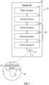
- the spacecraft 20 includes a control system 22 including one or more flight computers 24 that are in electronic communication with a plurality of sensing devices 26, one or more actuators 28, one or more power subsystems 30, and one or more antennas 32.
- a detailed diagram of an exemplary flight computer 24 is shown in FIG. 6 and is described below.
- the one or more actuators 28 include a plurality of internal actuators 28A and a plurality of external actuators 28B.
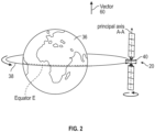
- the spacecraft 20 is configured to revolve around a celestial body 36 that is surrounded by an atmosphere. In the example as shown, the celestial body 36 is the Earth.
- the spacecraft 20 may orbit around any celestial body 36 having an atmosphere.
- the celestial body 36 is the planet Mars.
- aerodynamic torque is created.
- the control system 22 executes an attitude control strategy that reduces or substantially eliminates the aerodynamic torque, as well as other disturbance torques, exerted upon the spacecraft 20.
- the spacecraft 20 revolves in an orbit 38 around the celestial body 36.
- the sensing devices 26 detect the attitude of the spacecraft 20.
- the sensing devices 26 include, but not limited to, a star tracker, a gyroscope, a magnetometer, a sun sensor, an earth sensor, an accelerometer, and a global positioning system (GPS).
- the internal actuators 28A are momentum storage devices such as, but not limited to, reaction wheels and control moment gyroscopes.
- the external actuators 28B may also be referred to as momentum control actuators.
- the external actuators 28B exert a force upon the spacecraft 20 and include actuators such as, but not limited to, thrusters and magnetic torque rods.
- the thrusters include any type of thruster such as, but not limited to, chemical thrusters, ion thrusters and Hall thrusters.
- a chemical thruster generates thrust based on a chemical reaction such as, for example, oxidizing a fuel.
- the power subsystems 30 store and provide electrical power to the various components of the spacecraft 20 and include devices such as, but not limited to, solar panels, radioisotope thermoelectric generators, batteries, capacitor banks, and heat engines.
- FIG. 3 is an enlarged view of the spacecraft 20 shown in FIG. 2 .
- the spacecraft 20 includes a main body 40 that defines an axis that is aligned with a minor principal moment of inertia, which is referred to as a principal axis A-A.
- the principal axis A-A is positioned substantially perpendicular with respect to a roll axis R and a yaw axis Y of the main body 40 of the spacecraft 20.
- the principal axis A-A is also substantially aligned with a pitch axis P of the main body 40 of the spacecraft 20.
- the spacecraft 20 may include two or more solar wings 42A, 42B that project outward from the main body 40 of the spacecraft 20 that are attached to the main body 40 of the spacecraft 20.
- the solar wings 42A and 42B are substantially aligned with the principal axis A-A of the spacecraft 20, where the upper or north solar wing is designated as solar wing 42A and a lower or south solar wing is designated as solar wing 42B.
- a solar axis S-S of the spacecraft 20 is substantially aligned with the principal axis A-A.
- FIG. 3 illustrates solar wings 42A, 42B that derive electrical power from sunlight, it is to be appreciated that other electrical devices for generating power may be used as well.
- the orbit 38 around the celestial body 36 is shown as an elliptical orbit having a relatively high eccentricity (e.g., where the eccentricity e is about 0.8).
- the orbit 38 may have a relatively low eccentricity of about zero.
- a vector 60 is defined, where the vector 60 is substantially normal with respect to the orbit 38 that the spacecraft 20 follows around the celestial body 36.
- the orbit 38 around the celestial body 36 is an equatorial orbit. That is, the orbit 38 is substantially aligned with an equator E of the celestial body 36.
- the orbit 38 and the vector 60 may be positioned into orientations other than the illustration shown in FIG. 2 .
- the celestial body 36 may include an inclined orbit instead.
- the flight computers 24 of the spacecraft 20 are in wireless communication with a ground control system 50 by the antennas 32.
- the ground control system 50 may be located upon the celestial body 36 that the spacecraft 20 orbits around.
- the ground control system 50 may be located upon the Earth.
- the ground control system 50 may be located on Earth, but the spacecraft 20 may be orbiting another celestial body 36 that has an atmosphere.
- the ground control system 50 includes one or more computers that send and receive data from the flight computers 24 of the spacecraft 20.
- the ground control system 50 may send instructions to the flight computer 24.
- the spacecraft 20 may enter the safing mode in response to the flight computers 24 determining one or more pre-defined spacecraft safing criteria are met.
- the pre-defined spacecraft safing criteria includes data collected by the sensing devices 26 and other on-board data such as, but not limited to, solar wing current, temperature readings of the various components of the spacecraft 20, and stored momentum in a momentum storage device.
- the spacecraft 20 may enter the safing mode when the solar wing current is below a pre-defined current limit and the current conditions indicate the solar wings 42A, 42B should be generating a substantial amount of current.
- some other examples of when the spacecraft 20 enters the safing mode include when the temperature of a specific component (or multiple components) of the spacecraft 20 (e.g., a payload module) exceeds a pre-defined temperature limit, or when the stored momentum of one or the momentum storage devices exceed a pre-defined momentum limit.
- the ground control system 50 may transmit a signal to the spacecraft 20 indicating the spacecraft 20 is to enter the safing mode.
- the control system 22 Upon entering a safing mode, the control system 22 employs an attitude control strategy that is now described.
- the attitude control strategy includes reducing disturbances torques such as a gravity gradient torque and the aerodynamic torque.
- the disclosure describes reducing the gravity gradient torque and the aerodynamic torque separately, the control system 22 employs a single attitude control strategy that addresses both the gravity gradient torque and aerodynamic torque simultaneously.
- the spacecraft 20 is launched into space and revolves around the celestial body 36 while following the orbit 38.
- the flight computer 24 executes attitude control. Specifically, during attitude control, the flight computer 24 instructs the one or more actuators 28 to substantially align the principal axis A-A of the spacecraft 20 with the vector 60 that is normal to the orbit 38 around the celestial body 36. Aligning the principal axis A-A of the spacecraft 20 reduces or substantially eliminates gravity gradient torque. Gravity gradient torque is exerted upon the spacecraft 20 when a difference in gravitational forces between various sections or portions of the spacecraft 20 exists. In the example as shown in FIG. 2 , the solar wings 42A, 42B are each about equidistant from the celestial body 36. Accordingly, the gravitational force on each solar wing 42A, 42B of the spacecraft 20 is about equal, and therefore the gravity gradient torque is reduced or substantially eliminated.
- the flight computers 24 instruct the one or more actuators 28 to rotate the spacecraft 20 about the principal axis A-A at a constant rate, where a rotational orientation of the spacecraft 20 relative to the celestial body 36 is shifted by about one-half a rotation about the principal axis A-A each time the spacecraft 20 completes the orbit 38 around the celestial body 36.
- a first face 66 of the main body 40 of the spacecraft 20 would face the celestial body 36 as the spacecraft 20 completes a first orbit around the celestial body 36.
- a second face 68 of the main body 40 of the spacecraft 20 that is opposite to the first face 66 would face the celestial body 36 as the spacecraft completes a second orbit around the celestial body 36, where the second orbit is performed immediately after the first orbit.
- shifting the rotational orientation of the spacecraft 20 by about one-half a rotation about the principal axis A-A reduces or substantially eliminates disturbance torques exerted upon the spacecraft 20.
- the aerodynamic torque exerted upon the spacecraft 20 is reduced or substantially eliminated by shifting the rotational orientation of the spacecraft 20.
- other attitude-dependent torques such as magnetic disturbance torques, are also partially canceled as well.
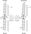
- FIG. 4A is an exemplary illustration of the spacecraft 20, where the spacecraft 20 has just completed a first orbit around the celestial body 36 ( FIG. 2 ).
- FIG. 4B is an illustration of the spacecraft 20, where the spacecraft 20 has just completed a second orbit around the celestial body 36. The first orbit and the second orbit are performed consecutively with respect to one another.
- a center of pressure 70 of the spacecraft 20 and a center of mass 72 of the spacecraft 20 are shown in both FIGS. 4A and 4B .
- the center of pressure 70 of the spacecraft 20 is located in a different position than the center of mass 72 of the spacecraft 20.
- a net torque T is exerted upon the spacecraft 20 because the center of pressure is 70 is offset from the center of mass 72.
- a first net torque T 1 exerted upon the spacecraft 20 while completing the first orbit is oriented around a first axis A 1 .
- a second net torque T 2 exerted upon the spacecraft 20 is oriented around a second axis A 2 .
- a sum of the first net torque T 1 and the second net torque T 2 is about zero. In other words, the first net torque T 1 and the second net torque T 2 partially cancel one another, and therefore the total net torque between the first orbit and the second orbit is reduced when compared to a spacecraft that does not rotate through the first and second orbit as described.
- the flight computer 24 instructs the one or more actuators 28 to rotate the spacecraft 20 a predetermined number of rotations about the principal axis A-A at a constant rate as the spacecraft 20 completes a single orbit around the celestial body 36.
- the spacecraft 20 would always rotate an extra one-half rotation about the principal axis A-A while completing a single orbit around the celestial body 36.
- the spacecraft 20 would rotate one and a half time about the principal axis A-A while completing a single orbit around the celestial body 36.
- the value N is determined based on one or more characteristics of the spacecraft 20.
- the value N may be determined based on one or more characteristics of the spacecraft that include: thermal characteristics of the spacecraft 20 based on proximity to a source of heat, a solar wing angle, a rate limit of the spacecraft 20, a momentum limit of the spacecraft 20, and a structural rate limit of the spacecraft 20.
- the thermal characteristics of the spacecraft 20 refer to heat generated by the sun. For example, sometimes it may not be ideal to heat a particular area of the spacecraft 20 above a specific temperature by the sun, and so the spacecraft 20 may need to rotate more rapidly around the principal axis A-A. Therefore, the value N may need to increase in order to accommodate the increased rotational speed.
- the solar wing angle is related to an amount of electrical power that is required by the spacecraft 20.
- the rotational speed that the spacecraft 20 rotates at about the principal axis A-A may either increase or decrease depending upon how much sunlight is required to produce the required electrical power.
- the rate limit of the spacecraft 20 represents a maximum speed at which the spacecraft 20 may rotate about a given axis.
- the momentum limit and structural rate limit of the spacecraft 20 are based on a momentum management limit of the spacecraft 20 and the structural limits of the spacecraft 20 respectively.
- the momentum limit represents a limit on the amount of momentum that the momentum storage devices may store.
- the structural rate limit represents the maximum rate at which the spacecraft 20 may rotate about any given axis without adversely affecting the spacecraft's structure.
- the one or more actuators 28 that align the principal axis A-A of the spacecraft 20 with the vector 60 may be selected from any of the internal actuators 28A and the external actuators 28B.
- the one or more actuators 28 that rotate the spacecraft 20 about the principal axis A-A may also be selected from any of the internal actuators 28A and the external actuators 28B.
- the actuators 28 used to align the principal axis A-A of the spacecraft 20 with the vector 60 may be different than the actuators 28 used to rotate the spacecraft 20 about the principal axis A-A.
- the one or more actuators 28 include at least one of the following: a control moment gyroscope, a reaction wheel, thrusters, and magnetic torque rods.
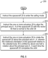
- FIG. 5 is a process flow diagram illustrating an exemplary method 200 for executing an attitude control strategy that reduces or substantially eliminates disturbance torques experienced by the spacecraft 20.
- the method 200 begins at block 202.
- the flight computers 24 instruct the spacecraft 20 to enter the safing mode.
- the flight computers 24 may determine that one or more pre-defined spacecraft safing criteria are met.
- the ground control system 50 may transmit a signal to the spacecraft 20 directly which causes the spacecraft to enter the safing mode.
- the method 200 may then proceed to block 204.
- the flight computers 24 instruct the one or more actuators 28 to align the principal axis A-A of the spacecraft 20 with the vector 60 that is normal to the orbit 38 around the celestial body 36.
- the method 200 may then proceed to block 206.
- the flight computers 24 instruct the one or more actuators 28 to rotate the spacecraft 20 about the principal axis A-A, where the rotational orientation of the spacecraft 20 relative to the celestial body 36 is shifted by about one-half a rotation about the principal axis A-A each time the spacecraft 20 completes the orbit 38 around the celestial body 36.
- the disclosed attitude control strategy provides various technical effect and benefits by reducing or substantially eliminating disturbance torques upon the spacecraft while also reducing the need for momentum control actuators, such as thrusters and magnetic torque rods, during safing mode.
- the disclosed spacecraft may require smaller momentum control actuators. Accordingly, the mass of the spacecraft is reduced, which results in fuel savings.
- Many conventional approaches for controlling a spacecraft in safing mode may extensively utilize momentum control devices. It is also to be appreciated some conventional approaches for controlling movement of the spacecraft during safing mode may also require complete ephemeris knowledge of the spacecraft.
- the disclosed attitude control strategy only requires partial ephemeris knowledge (i.e., the orbit normal vector in inertial space) and the inertial attitude to operate.
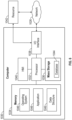
- the flight computer 24 and the ground control system 50 are implemented on one or more computer devices or systems, such as exemplary computer system 1030.
- the computer system 1030 includes a processor 1032, a memory 1034, a mass storage memory device 1036, an input/output (I/O) interface 1038, and a Human Machine Interface (HMI) 1040.
- the computer system 1030 is operatively coupled to one or more external resources 1042 via the network 1026 or I/O interface 1038.
- External resources may include, but are not limited to, servers, databases, mass storage devices, peripheral devices, cloud-based network services, or any other suitable computer resource that may be used by the computer system 1030.
- the processor 1032 includes one or more devices selected from microprocessors, microcontrollers, digital signal processors, microcomputers, central processing units, field programmable gate arrays, programmable logic devices, state machines, logic circuits, analog circuits, digital circuits, or any other devices that manipulate signals (analog or digital) based on operational instructions that are stored in the memory 1034.
- Memory 1034 includes a single memory device or a plurality of memory devices including, but not limited to, read-only memory (ROM), random access memory (RAM), volatile memory, non-volatile memory, static random-access memory (SRAM), dynamic random-access memory (DRAM), flash memory, cache memory, or any other device capable of storing information.
- the mass storage memory device 1036 includes data storage devices such as a hard drive, optical drive, tape drive, volatile or non-volatile solid-state device, or any other device capable of storing information.
- the processor 1032 operates under the control of an operating system 1046 that resides in memory 1034.
- the operating system 1046 manages computer resources so that computer program code embodied as one or more computer software applications, such as an application 1048 residing in memory 1034, may have instructions executed by the processor 1032.
- the processor 1032 may execute the application 1048 directly, in which case the operating system 1046 may be omitted.
- One or more data structures 1049 also reside in memory 1034, and may be used by the processor 1032, operating system 1046, or application 1048 to store or manipulate data.
- the I/O interface 1038 provides a machine interface that operatively couples the processor 1032 to other devices and systems, such as the network 1026 or external resource 1042.
- the application 1048 thereby works cooperatively with the network 1026 or external resource 1042 by communicating via the I/O interface 1038 to provide the various features, functions, applications, processes, or modules comprising examples of the invention.
- the application 1048 also includes program code that is executed by one or more external resources 1042, or otherwise rely on functions or signals provided by other system or network components external to the computer system 1030.
- examples of the invention may include applications that are located externally to the computer system 1030, distributed among multiple computers or other external resources 1042, or provided by computing resources (hardware and software) that are provided as a service over the network 1026, such as a cloud computing service.
- the HMI 1040 is operatively coupled to the processor 1032 of computer system 1030 in a known manner to allow a user to interact directly with the computer system 1030.
- the HMI 1040 may include video or alphanumeric displays, a touch screen, a speaker, and any other suitable audio and visual indicators capable of providing data to the user.
- the HMI 1040 also includes input devices and controls such as an alphanumeric keyboard, a pointing device, keypads, pushbuttons, control knobs, microphones, etc., capable of accepting commands or input from the user and transmitting the entered input to the processor 1032.
- a database 1044 may reside on the mass storage memory device 1036 and may be used to collect and organize data used by the various systems and modules described herein.
- the database 1044 may include data and supporting data structures that store and organize the data.
- the database 1044 may be arranged with any database organization or structure including, but not limited to, a relational database, a hierarchical database, a network database, or combinations thereof.
- a database management system in the form of a computer software application executing as instructions on the processor 1032 may be used to access the information or data stored in records of the database 1044 in response to a query, where a query may be dynamically determined and executed by the operating system 1046, other applications 1048, or one or more modules.
Landscapes
- Engineering & Computer Science (AREA)
- Remote Sensing (AREA)
- Chemical & Material Sciences (AREA)
- Combustion & Propulsion (AREA)
- Radar, Positioning & Navigation (AREA)
- Aviation & Aerospace Engineering (AREA)
- Automation & Control Theory (AREA)
- Control Of Position, Course, Altitude, Or Attitude Of Moving Bodies (AREA)
Claims (12)
- Raumfahrzeug (20), umfassend:einen Hauptkörper (40), der eine Hauptachse (A-A) definiert;zwei oder mehr Solarflügel (42A, 42B), wobei die zwei oder mehr Solarflügel (42A, 42B) im Wesentlichen mit der Hauptachse (A-A) des Hauptkörpers (40) des Raumfahrzeugs (20) ausgerichtet sind; undein Steuersystem (22), umfassend:einen oder mehrere Aktuatoren (28);einen oder mehrere Prozessoren (1032) in elektronischer Kommunikation mit dem einen oder den mehreren Aktuatoren (28); undeinen Speicher (1034), der mit dem einen oder den mehreren Prozessoren (1032) gekoppelt ist, wobei der Speicher (1034) Daten in eine Datenbank (1044) und Programmcode speichert, der, wenn er durch den einen oder die mehreren Prozessoren (1032) ausgeführt wird, das Steuersystem (22) veranlasst zum:Anweisen des Raumfahrzeugs (20), in einen Sicherheitsmodus einzutreten, wobei das Raumfahrzeug (20) in einer Umlaufbahn (38) um einen Himmelskörper (36), der eine Atmosphäre aufweist, kreist;als Reaktion auf das Eintreten in den Sicherheitsmodus, Anweisen des einen oder der mehreren Aktuatoren (28), eine Hauptachse (A-A) des Raumfahrzeugs (20) im Wesentlichen mit einem Vektor (60) auszurichten, der normal zu der Umlaufbahn (38) um den Himmelskörper (36) ist; undAnweisen des einen oder der mehreren Aktuatoren (28), das Raumfahrzeug (20) um die Hauptachse (A-A) zu drehen, dadurch gekennzeichnet, dass eine Drehorientierung des Raumfahrzeugs (20) relativ zu dem Himmelskörper (36) jedes Mal, wenn das Raumfahrzeug (20) die Umlaufbahn (38) um den Himmelskörper (36) vollendet, um etwa eine halbe Drehung um die Hauptachse (A-A) verschoben wird.
- Raumfahrzeug (20) nach Anspruch 1, wobei der eine oder die mehreren Prozessoren (1032) Anweisungen ausführen zum:
Anweisen des einen oder der mehreren Aktuatoren (28), das Raumfahrzeug (20) eine zuvor bestimmte Anzahl von Drehungen mit einer konstanten Geschwindigkeit um die Hauptachse (A-A) zu drehen, während das Raumfahrzeug (20) eine einzelne Umlaufbahn (38) um den Himmelskörper (36) vollendet. - Raumfahrzeug (20) nach Anspruch 2, wobei die zuvor bestimmte Anzahl von Drehungen pro Umlaufbahn (38) bestimmt wird durch:

- Raumfahrzeug (20) nach Anspruch 3, wobei der Wert N basierend auf einer oder mehreren Eigenschaften des Raumfahrzeugs (20) bestimmt wird, die einschließen: thermische Eigenschaften des Raumfahrzeugs (20) basierend auf einer Nähe zu einer Wärmequelle, einen Solarflügelwinkel, eine Geschwindigkeitsgrenze des Raumfahrzeugs (20), eine Impulsgrenze des Raumfahrzeugs (20) und eine strukturelle Geschwindigkeitsgrenze des Raumfahrzeugs (20).
- Raumfahrzeug (20) nach einem der Ansprüche 1 bis 4, ferner umfassend eine Antenne (32) in elektronischer Kommunikation mit dem einen oder den mehreren Prozessoren (1032), wobei die Antenne (32) konfiguriert ist, um in Drahtloskommunikation mit einem Bodenkontrollsystem (50) zu stehen.
- Raumfahrzeug (20) nach Anspruch 5, wobei sich das Bodenkontrollsystem (50, 22) auf der Erde befindet.
- Raumfahrzeug (20) nach einem der Ansprüche 1 bis 6, wobei der eine oder die mehreren Aktuatoren (28) mindestens eines einschließen von einem Steuermomentgyroskop, einem Reaktionsrad, Triebwerke und magnetische Drehmomentstäbe.
- Verfahren (200) zum Reduzieren von Stördrehmomenten, denen ein Raumfahrzeug (20) ausgesetzt ist, umfassend einen Hauptkörper (40), der eine Hauptachse (A-A) definiert, und zwei oder mehr Solarflügel (42A, 42B), wobei die zwei oder mehr Solarflügel (42A, 42B) im Wesentlichen mit der Hauptachse (A-A) des Hauptkörpers (40) des Raumfahrzeugs (20) ausgerichtet sind, das Verfahren (200) umfassend:Anweisen (202) des Raumfahrzeugs (20) durch einen Computer (24), in einen Sicherheitsmodus einzutreten, wobei das Raumfahrzeug (20) in einer Umlaufbahn (38) um einen durch eine Atmosphäre umgebenen Himmelskörper (36) kreist;als Reaktion auf das Eintreten in den Sicherungsmodus, Anweisen (204), durch den Computer (24), eines oder mehrerer Aktuatoren (28) des Raumfahrzeugs (20), eine Hauptachse (A-A) des Raumfahrzeugs (20) im Wesentlichen mit einem Vektor (60) auszurichten, der normal zu der Umlaufbahn (38) um den Himmelskörper (36) ist; undAnweisen (206) des einen oder der mehreren Aktuatoren (28), das Raumfahrzeug (20) um die Hauptachse (A-A) zu drehen, dadurch gekennzeichnet, dass eine Drehorientierung des Raumfahrzeugs (20) relativ zu dem Himmelskörper (36) jedes Mal, wenn das Raumfahrzeug (20) die Umlaufbahn (38) um den Himmelskörper (36) vollendet, um etwa eine halbe Drehung um die Hauptachse (A-A) verschoben wird.
- Verfahren (200) nach Anspruch 8, ferner umfassend:
Anweisen des einen oder der mehreren Aktuatoren (28), das Raumfahrzeug (20) eine zuvor bestimmte Anzahl von Drehungen mit einer konstanten Geschwindigkeit um die Hauptachse (A-A) zu drehen, während das Raumfahrzeug (20) eine einzelne Umlaufbahn (38) um den Himmelskörper (36) vollendet. - Verfahren (200) nach Anspruch 9, ferner umfassend das Bestimmen der zuvor bestimmten Anzahl von Drehungen pro Umlaufbahn (38), wobei die zuvor bestimmte Anzahl von Drehungen pro Umlaufbahn (38) bestimmt wird durch:

wobei ein Wert N eine positive Ganzzahl einschließlich null darstellt. - Verfahren (200) nach Anspruch 10,
wobei der Wert N auf einer oder mehreren Eigenschaften des Raumfahrzeugs (20) basiert, die einschließen: thermische Eigenschaften des Raumfahrzeugs (20) basierend auf einer Nähe zu einer Wärmequelle, einen Solarflügelwinkel, eine Geschwindigkeitsgrenze des Raumfahrzeugs (20), eine Impulsgrenze des Raumfahrzeugs (20) und eine strukturelle Geschwindigkeitsgrenze des Raumfahrzeugs (20). - Verfahren (200) nach einem der Ansprüche 8 bis 11, ferner umfassend:
Anweisen (202) des Raumfahrzeugs (20), in den Sicherheitsmodus einzutreten, wenn der Solarflügelstrom unter einer vordefinierten Stromgrenze liegt und Strombedingungen anzeigen, dass die Solarflügel (42A, 42B) eine Strommenge über der vordefinierten Stromgrenze erzeugen sollten.
Applications Claiming Priority (1)
| Application Number | Priority Date | Filing Date | Title |
|---|---|---|---|
| US16/425,296 US11273933B2 (en) | 2019-05-29 | 2019-05-29 | Spacecraft attitude control strategy for reducing disturbance torques |
Publications (2)
| Publication Number | Publication Date |
|---|---|
| EP3744645A1 EP3744645A1 (de) | 2020-12-02 |
| EP3744645B1 true EP3744645B1 (de) | 2024-10-30 |
Family
ID=70804478
Family Applications (1)
| Application Number | Title | Priority Date | Filing Date |
|---|---|---|---|
| EP20175966.9A Active EP3744645B1 (de) | 2019-05-29 | 2020-05-22 | Lagesteuerungsstrategie eines raumfahrzeugs zur reduzierung von störmomenten |
Country Status (2)
| Country | Link |
|---|---|
| US (1) | US11273933B2 (de) |
| EP (1) | EP3744645B1 (de) |
Families Citing this family (6)
| Publication number | Priority date | Publication date | Assignee | Title |
|---|---|---|---|---|
| US11338944B2 (en) | 2019-05-29 | 2022-05-24 | GM Global Technology Operations LLC | Control system for executing a safing mode sequence in a spacecraft |
| US11174047B2 (en) | 2019-05-29 | 2021-11-16 | The Boeing Company | Spacecraft control system for determining reaction torque |
| CN111209523B (zh) * | 2020-01-06 | 2020-12-29 | 中国科学院紫金山天文台 | 适用于大偏心率轨道密集星历精密计算的快速处理方法 |
| FR3110549A1 (fr) * | 2020-05-19 | 2021-11-26 | Airbus Defence And Space Sas | Procédé d’optimisation du transfert d’orbite d’un engin spatial à propulsion électrique et satellite mettant en œuvre ledit procédé |
| CN117184456B (zh) * | 2023-11-08 | 2024-01-30 | 北京控制工程研究所 | 轨控发动机干扰力矩的估计方法、装置、设备及介质 |
| FR3160679A1 (fr) * | 2024-03-26 | 2025-10-03 | Airbus Defence And Space Sas | Procédé de contrôle d'attitude en mode survie d'un satellite embarquant un instrument sensible au rayonnement solaire |
Family Cites Families (22)
| Publication number | Priority date | Publication date | Assignee | Title |
|---|---|---|---|---|
| US6021979A (en) | 1993-07-19 | 2000-02-08 | Hughes Electronics Corporation | Sun-referenced safe-hold control for momentum biased satellites |
| FR2742243B1 (fr) * | 1995-12-06 | 1998-02-13 | Matra Marconi Space France | Procede de commande d'attitude d'un satellite en orbite basse, a acquisition solaire |
| US6205378B1 (en) | 1999-07-29 | 2001-03-20 | Space Systems/Loral, Inc. | Adaptive mass expulsion attitude control system |
| US6318676B1 (en) | 2000-01-10 | 2001-11-20 | Space Systems/Loral, Inc. | Equatorial-normal body-stabilized spacecraft and control method for inclined orbit operation |
| US6681182B2 (en) | 2002-02-01 | 2004-01-20 | The Aerospace Corporation | Fault detection pseudo gyro |
| US6921050B2 (en) | 2003-01-17 | 2005-07-26 | Northrop Grumman Corporation | Solar torque control using thin film directionally reflective, emissive, absorptive and transmissive surfaces |
| US7546983B2 (en) | 2003-12-03 | 2009-06-16 | The Boeing Company | Spacecraft power acquisition method for wing-stowed configuration |
| US7823836B2 (en) * | 2006-12-04 | 2010-11-02 | The Boeing Company | Optimal sun safe attitude for satellite ground tracking |
| FR2937954B1 (fr) * | 2008-10-31 | 2011-07-29 | Thales Sa | Procede et systeme de desaturation des roues d'inertie d'un engin spatial |
| US8315749B2 (en) | 2010-01-11 | 2012-11-20 | Che-Hang Charles Ih | Innovative optimal spacecraft safing methodology |
| FR2990930B1 (fr) | 2012-05-25 | 2014-06-27 | Thales Sa | Systeme de propulsion pour controle d'orbite et controle d'attitude de satellite |
| FR2994287B1 (fr) | 2012-08-03 | 2016-11-04 | Thales Sa | Dispositif et procede pour desorbitation de satellite |
| FR3022530B1 (fr) * | 2014-06-19 | 2018-03-02 | Airbus Defence And Space Sas | Procede de controle d'orbite d'un satellite en orbite terrestre, satellite et systeme de controle d'orbite d'un tel satellite |
| US20160116639A1 (en) | 2014-10-24 | 2016-04-28 | Alexander J. Engell | Apparatus, system and method to mitigate risk of adverse operational environmental effects |
| US9889950B2 (en) * | 2015-02-20 | 2018-02-13 | Space Systems/Loral, Llc | Spacecraft with aerodynamic control |
| US10464694B1 (en) * | 2017-03-23 | 2019-11-05 | Space Systems/Loral, Llc | Asymmetric thruster gimbal configuration |
| US10538342B2 (en) | 2017-05-23 | 2020-01-21 | Space Systems/Loral, Llc | Ecliptic sun acquisition control mode for satellites |
| DE112018003621B4 (de) * | 2017-07-14 | 2026-04-02 | Deutsches Zentrum für Luft- und Raumfahrt e.V. | Navigationssatellit, insbesondere für einen medium earth orbit |
| US11242162B2 (en) | 2018-03-27 | 2022-02-08 | Massachusetts Institute Of Technology | Methods and apparatus for in-situ measurements of atmospheric density |
| FR3093998B1 (fr) * | 2019-03-20 | 2021-09-10 | Airbus Defence & Space Sas | Procédé de contrôle d’attitude d’un satellite en mode survie sans connaissance a priori de l’heure locale de l’orbite du satellite |
| US11174047B2 (en) | 2019-05-29 | 2021-11-16 | The Boeing Company | Spacecraft control system for determining reaction torque |
| US11338944B2 (en) | 2019-05-29 | 2022-05-24 | GM Global Technology Operations LLC | Control system for executing a safing mode sequence in a spacecraft |
-
2019
- 2019-05-29 US US16/425,296 patent/US11273933B2/en active Active
-
2020
- 2020-05-22 EP EP20175966.9A patent/EP3744645B1/de active Active
Also Published As
| Publication number | Publication date |
|---|---|
| US20200377235A1 (en) | 2020-12-03 |
| EP3744645A1 (de) | 2020-12-02 |
| US11273933B2 (en) | 2022-03-15 |
Similar Documents
| Publication | Publication Date | Title |
|---|---|---|
| EP3744645B1 (de) | Lagesteuerungsstrategie eines raumfahrzeugs zur reduzierung von störmomenten | |
| Gong et al. | Review on solar sail technology | |
| Leve et al. | Spacecraft momentum control systems | |
| CN104527994B (zh) | 异面交叉快变轨道固定时间稳定姿态指向跟踪控制方法 | |
| US5692707A (en) | Universal spacecraft attitude steering control system | |
| CN111688952A (zh) | 一种卫星姿态控制系统 | |
| US7823836B2 (en) | Optimal sun safe attitude for satellite ground tracking | |
| Carrara | An open source satellite attitude and orbit simulator toolbox for Matlab | |
| US11738888B2 (en) | Momentum wheels and reaction wheels for objects in space | |
| US11174047B2 (en) | Spacecraft control system for determining reaction torque | |
| EP0287572B1 (de) | Verfahren zur steuerung eines sich schnell drehenden körpers in einer umlaufbahn | |
| US11338944B2 (en) | Control system for executing a safing mode sequence in a spacecraft | |
| Starin et al. | Attitude determination and control systems | |
| Defendini et al. | Low cost CMG-based AOCS designs | |
| Romero Calvo et al. | Attitude control for the Lumio Cubesat in deep space | |
| Williams | Launch window analysis for the Magnetospheric Multiscale Mission | |
| Van Der Stokker | An investigation into the imager pointing accuracy and stability for a CubeSat Using a CubeADCS in sun-synchronous low earth orbits | |
| Wilson | A high-temperature superconductor energy-momentum control system for small satellites | |
| Aghili et al. | Dumping momentum on the Lunar Gateway using a robotically steerable solar sail | |
| Ibrahim | Attitude and orbit control of small satellites for autonomous terrestrial target tracking | |
| Hsieh et al. | Attitude Determination and Control System With Variable-Speed Single-Gimbal Control Moment Gyroscopes for Nanosatellites | |
| Abezyaev | On One Possibility of Orientation of a Near-Earth Spacecraft in the Earth’s Magnetic Field | |
| Legostaev | Russian space programs: Achievements and prospects of automatic control applications | |
| Nadeau | Investigation of Trajectory and Control Designs for a Solar Sail to the Moon | |
| Rieger | Modeling of Attitude Determination and Control Subsystem (ADCS) for a 6U CubeSat for Tracking Objects in Space |
Legal Events
| Date | Code | Title | Description |
|---|---|---|---|
| PUAI | Public reference made under article 153(3) epc to a published international application that has entered the european phase |
Free format text: ORIGINAL CODE: 0009012 |
|
| STAA | Information on the status of an ep patent application or granted ep patent |
Free format text: STATUS: THE APPLICATION HAS BEEN PUBLISHED |
|
| AK | Designated contracting states |
Kind code of ref document: A1 Designated state(s): AL AT BE BG CH CY CZ DE DK EE ES FI FR GB GR HR HU IE IS IT LI LT LU LV MC MK MT NL NO PL PT RO RS SE SI SK SM TR |
|
| AX | Request for extension of the european patent |
Extension state: BA ME |
|
| STAA | Information on the status of an ep patent application or granted ep patent |
Free format text: STATUS: REQUEST FOR EXAMINATION WAS MADE |
|
| 17P | Request for examination filed |
Effective date: 20210601 |
|
| RBV | Designated contracting states (corrected) |
Designated state(s): AL AT BE BG CH CY CZ DE DK EE ES FI FR GB GR HR HU IE IS IT LI LT LU LV MC MK MT NL NO PL PT RO RS SE SI SK SM TR |
|
| STAA | Information on the status of an ep patent application or granted ep patent |
Free format text: STATUS: EXAMINATION IS IN PROGRESS |
|
| 17Q | First examination report despatched |
Effective date: 20220214 |
|
| RAP3 | Party data changed (applicant data changed or rights of an application transferred) |
Owner name: THE BOEING COMPANY |
|
| REG | Reference to a national code |
Ref country code: DE Ref legal event code: R079 Free format text: PREVIOUS MAIN CLASS: B64G0001240000 Ipc: B64G0001280000 Ref country code: DE Ref legal event code: R079 Ref document number: 602020040156 Country of ref document: DE Free format text: PREVIOUS MAIN CLASS: B64G0001240000 Ipc: B64G0001280000 |
|
| GRAP | Despatch of communication of intention to grant a patent |
Free format text: ORIGINAL CODE: EPIDOSNIGR1 |
|
| STAA | Information on the status of an ep patent application or granted ep patent |
Free format text: STATUS: GRANT OF PATENT IS INTENDED |
|
| RIC1 | Information provided on ipc code assigned before grant |
Ipc: B64G 1/24 20060101ALI20240429BHEP Ipc: B64G 1/28 20060101AFI20240429BHEP |
|
| INTG | Intention to grant announced |
Effective date: 20240521 |
|
| GRAS | Grant fee paid |
Free format text: ORIGINAL CODE: EPIDOSNIGR3 |
|
| GRAA | (expected) grant |
Free format text: ORIGINAL CODE: 0009210 |
|
| STAA | Information on the status of an ep patent application or granted ep patent |
Free format text: STATUS: THE PATENT HAS BEEN GRANTED |
|
| AK | Designated contracting states |
Kind code of ref document: B1 Designated state(s): AL AT BE BG CH CY CZ DE DK EE ES FI FR GB GR HR HU IE IS IT LI LT LU LV MC MK MT NL NO PL PT RO RS SE SI SK SM TR |
|
| REG | Reference to a national code |
Ref country code: GB Ref legal event code: FG4D |
|
| REG | Reference to a national code |
Ref country code: CH Ref legal event code: EP |
|
| REG | Reference to a national code |
Ref country code: DE Ref legal event code: R096 Ref document number: 602020040156 Country of ref document: DE |
|
| REG | Reference to a national code |
Ref country code: IE Ref legal event code: FG4D |
|
| P01 | Opt-out of the competence of the unified patent court (upc) registered |
Free format text: CASE NUMBER: APP_57133/2024 Effective date: 20241018 |
|
| REG | Reference to a national code |
Ref country code: LT Ref legal event code: MG9D |
|
| REG | Reference to a national code |
Ref country code: NL Ref legal event code: MP Effective date: 20241030 |
|
| PG25 | Lapsed in a contracting state [announced via postgrant information from national office to epo] |
Ref country code: IS Free format text: LAPSE BECAUSE OF FAILURE TO SUBMIT A TRANSLATION OF THE DESCRIPTION OR TO PAY THE FEE WITHIN THE PRESCRIBED TIME-LIMIT Effective date: 20250228 Ref country code: PT Free format text: LAPSE BECAUSE OF FAILURE TO SUBMIT A TRANSLATION OF THE DESCRIPTION OR TO PAY THE FEE WITHIN THE PRESCRIBED TIME-LIMIT Effective date: 20250228 Ref country code: HR Free format text: LAPSE BECAUSE OF FAILURE TO SUBMIT A TRANSLATION OF THE DESCRIPTION OR TO PAY THE FEE WITHIN THE PRESCRIBED TIME-LIMIT Effective date: 20241030 |
|
| PG25 | Lapsed in a contracting state [announced via postgrant information from national office to epo] |
Ref country code: NL Free format text: LAPSE BECAUSE OF FAILURE TO SUBMIT A TRANSLATION OF THE DESCRIPTION OR TO PAY THE FEE WITHIN THE PRESCRIBED TIME-LIMIT Effective date: 20241030 Ref country code: FI Free format text: LAPSE BECAUSE OF FAILURE TO SUBMIT A TRANSLATION OF THE DESCRIPTION OR TO PAY THE FEE WITHIN THE PRESCRIBED TIME-LIMIT Effective date: 20241030 |
|
| REG | Reference to a national code |
Ref country code: AT Ref legal event code: MK05 Ref document number: 1736679 Country of ref document: AT Kind code of ref document: T Effective date: 20241030 |
|
| PG25 | Lapsed in a contracting state [announced via postgrant information from national office to epo] |
Ref country code: BG Free format text: LAPSE BECAUSE OF FAILURE TO SUBMIT A TRANSLATION OF THE DESCRIPTION OR TO PAY THE FEE WITHIN THE PRESCRIBED TIME-LIMIT Effective date: 20241030 |
|
| PG25 | Lapsed in a contracting state [announced via postgrant information from national office to epo] |
Ref country code: ES Free format text: LAPSE BECAUSE OF FAILURE TO SUBMIT A TRANSLATION OF THE DESCRIPTION OR TO PAY THE FEE WITHIN THE PRESCRIBED TIME-LIMIT Effective date: 20241030 |
|
| PG25 | Lapsed in a contracting state [announced via postgrant information from national office to epo] |
Ref country code: NO Free format text: LAPSE BECAUSE OF FAILURE TO SUBMIT A TRANSLATION OF THE DESCRIPTION OR TO PAY THE FEE WITHIN THE PRESCRIBED TIME-LIMIT Effective date: 20250130 |
|
| PG25 | Lapsed in a contracting state [announced via postgrant information from national office to epo] |
Ref country code: LV Free format text: LAPSE BECAUSE OF FAILURE TO SUBMIT A TRANSLATION OF THE DESCRIPTION OR TO PAY THE FEE WITHIN THE PRESCRIBED TIME-LIMIT Effective date: 20241030 Ref country code: AT Free format text: LAPSE BECAUSE OF FAILURE TO SUBMIT A TRANSLATION OF THE DESCRIPTION OR TO PAY THE FEE WITHIN THE PRESCRIBED TIME-LIMIT Effective date: 20241030 Ref country code: GR Free format text: LAPSE BECAUSE OF FAILURE TO SUBMIT A TRANSLATION OF THE DESCRIPTION OR TO PAY THE FEE WITHIN THE PRESCRIBED TIME-LIMIT Effective date: 20250131 |
|
| PG25 | Lapsed in a contracting state [announced via postgrant information from national office to epo] |
Ref country code: PL Free format text: LAPSE BECAUSE OF FAILURE TO SUBMIT A TRANSLATION OF THE DESCRIPTION OR TO PAY THE FEE WITHIN THE PRESCRIBED TIME-LIMIT Effective date: 20241030 |
|
| PG25 | Lapsed in a contracting state [announced via postgrant information from national office to epo] |
Ref country code: RS Free format text: LAPSE BECAUSE OF FAILURE TO SUBMIT A TRANSLATION OF THE DESCRIPTION OR TO PAY THE FEE WITHIN THE PRESCRIBED TIME-LIMIT Effective date: 20250130 |
|
| PG25 | Lapsed in a contracting state [announced via postgrant information from national office to epo] |
Ref country code: SM Free format text: LAPSE BECAUSE OF FAILURE TO SUBMIT A TRANSLATION OF THE DESCRIPTION OR TO PAY THE FEE WITHIN THE PRESCRIBED TIME-LIMIT Effective date: 20241030 |
|
| PGFP | Annual fee paid to national office [announced via postgrant information from national office to epo] |
Ref country code: DE Payment date: 20250529 Year of fee payment: 6 |
|
| PG25 | Lapsed in a contracting state [announced via postgrant information from national office to epo] |
Ref country code: DK Free format text: LAPSE BECAUSE OF FAILURE TO SUBMIT A TRANSLATION OF THE DESCRIPTION OR TO PAY THE FEE WITHIN THE PRESCRIBED TIME-LIMIT Effective date: 20241030 |
|
| PGFP | Annual fee paid to national office [announced via postgrant information from national office to epo] |
Ref country code: GB Payment date: 20250527 Year of fee payment: 6 |
|
| PG25 | Lapsed in a contracting state [announced via postgrant information from national office to epo] |
Ref country code: EE Free format text: LAPSE BECAUSE OF FAILURE TO SUBMIT A TRANSLATION OF THE DESCRIPTION OR TO PAY THE FEE WITHIN THE PRESCRIBED TIME-LIMIT Effective date: 20241030 |
|
| PGFP | Annual fee paid to national office [announced via postgrant information from national office to epo] |
Ref country code: FR Payment date: 20250526 Year of fee payment: 6 |
|
| PG25 | Lapsed in a contracting state [announced via postgrant information from national office to epo] |
Ref country code: RO Free format text: LAPSE BECAUSE OF FAILURE TO SUBMIT A TRANSLATION OF THE DESCRIPTION OR TO PAY THE FEE WITHIN THE PRESCRIBED TIME-LIMIT Effective date: 20241030 |
|
| PG25 | Lapsed in a contracting state [announced via postgrant information from national office to epo] |
Ref country code: SK Free format text: LAPSE BECAUSE OF FAILURE TO SUBMIT A TRANSLATION OF THE DESCRIPTION OR TO PAY THE FEE WITHIN THE PRESCRIBED TIME-LIMIT Effective date: 20241030 |
|
| PG25 | Lapsed in a contracting state [announced via postgrant information from national office to epo] |
Ref country code: CZ Free format text: LAPSE BECAUSE OF FAILURE TO SUBMIT A TRANSLATION OF THE DESCRIPTION OR TO PAY THE FEE WITHIN THE PRESCRIBED TIME-LIMIT Effective date: 20241030 |
|
| PG25 | Lapsed in a contracting state [announced via postgrant information from national office to epo] |
Ref country code: IT Free format text: LAPSE BECAUSE OF FAILURE TO SUBMIT A TRANSLATION OF THE DESCRIPTION OR TO PAY THE FEE WITHIN THE PRESCRIBED TIME-LIMIT Effective date: 20241030 |
|
| REG | Reference to a national code |
Ref country code: DE Ref legal event code: R097 Ref document number: 602020040156 Country of ref document: DE |
|
| PLBE | No opposition filed within time limit |
Free format text: ORIGINAL CODE: 0009261 |
|
| STAA | Information on the status of an ep patent application or granted ep patent |
Free format text: STATUS: NO OPPOSITION FILED WITHIN TIME LIMIT |
|
| PG25 | Lapsed in a contracting state [announced via postgrant information from national office to epo] |
Ref country code: SE Free format text: LAPSE BECAUSE OF FAILURE TO SUBMIT A TRANSLATION OF THE DESCRIPTION OR TO PAY THE FEE WITHIN THE PRESCRIBED TIME-LIMIT Effective date: 20241030 |
|
| 26N | No opposition filed |
Effective date: 20250731 |
|
| REG | Reference to a national code |
Ref country code: CH Ref legal event code: H13 Free format text: ST27 STATUS EVENT CODE: U-0-0-H10-H13 (AS PROVIDED BY THE NATIONAL OFFICE) Effective date: 20251223 |
|
| PG25 | Lapsed in a contracting state [announced via postgrant information from national office to epo] |
Ref country code: LU Free format text: LAPSE BECAUSE OF NON-PAYMENT OF DUE FEES Effective date: 20250522 |
|
| PG25 | Lapsed in a contracting state [announced via postgrant information from national office to epo] |
Ref country code: CH Free format text: LAPSE BECAUSE OF NON-PAYMENT OF DUE FEES Effective date: 20250531 |
|
| REG | Reference to a national code |
Ref country code: BE Ref legal event code: MM Effective date: 20250531 |
|
| PG25 | Lapsed in a contracting state [announced via postgrant information from national office to epo] |
Ref country code: MC Free format text: LAPSE BECAUSE OF FAILURE TO SUBMIT A TRANSLATION OF THE DESCRIPTION OR TO PAY THE FEE WITHIN THE PRESCRIBED TIME-LIMIT Effective date: 20241030 |
|
| PG25 | Lapsed in a contracting state [announced via postgrant information from national office to epo] |
Ref country code: IE Free format text: LAPSE BECAUSE OF NON-PAYMENT OF DUE FEES Effective date: 20250522 |
|
| PG25 | Lapsed in a contracting state [announced via postgrant information from national office to epo] |
Ref country code: BE Free format text: LAPSE BECAUSE OF NON-PAYMENT OF DUE FEES Effective date: 20250531 |