EP3744877B1 - Hochfeste keramische fasern und deren herstellungsverfahren - Google Patents
Hochfeste keramische fasern und deren herstellungsverfahren Download PDFInfo
- Publication number
- EP3744877B1 EP3744877B1 EP20167062.7A EP20167062A EP3744877B1 EP 3744877 B1 EP3744877 B1 EP 3744877B1 EP 20167062 A EP20167062 A EP 20167062A EP 3744877 B1 EP3744877 B1 EP 3744877B1
- Authority
- EP
- European Patent Office
- Prior art keywords
- fibers
- fiber
- layer region
- matrix
- outer layer
- Prior art date
- Legal status (The legal status is an assumption and is not a legal conclusion. Google has not performed a legal analysis and makes no representation as to the accuracy of the status listed.)
- Active
Links
Images






Classifications
-
- C—CHEMISTRY; METALLURGY
- C01—INORGANIC CHEMISTRY
- C01B—NON-METALLIC ELEMENTS; COMPOUNDS THEREOF; METALLOIDS OR COMPOUNDS THEREOF NOT COVERED BY SUBCLASS C01C
- C01B32/00—Carbon; Compounds thereof
- C01B32/90—Carbides
- C01B32/914—Carbides of single elements
- C01B32/956—Silicon carbide
-
- C—CHEMISTRY; METALLURGY
- C04—CEMENTS; CONCRETE; ARTIFICIAL STONE; CERAMICS; REFRACTORIES
- C04B—LIME, MAGNESIA; SLAG; CEMENTS; COMPOSITIONS THEREOF, e.g. MORTARS, CONCRETE OR LIKE BUILDING MATERIALS; ARTIFICIAL STONE; CERAMICS; REFRACTORIES; TREATMENT OF NATURAL STONE
- C04B35/00—Shaped ceramic products characterised by their composition; Ceramics compositions; Processing powders of inorganic compounds preparatory to the manufacturing of ceramic products
- C04B35/515—Shaped ceramic products characterised by their composition; Ceramics compositions; Processing powders of inorganic compounds preparatory to the manufacturing of ceramic products based on non-oxide ceramics
-
- C—CHEMISTRY; METALLURGY
- C04—CEMENTS; CONCRETE; ARTIFICIAL STONE; CERAMICS; REFRACTORIES
- C04B—LIME, MAGNESIA; SLAG; CEMENTS; COMPOSITIONS THEREOF, e.g. MORTARS, CONCRETE OR LIKE BUILDING MATERIALS; ARTIFICIAL STONE; CERAMICS; REFRACTORIES; TREATMENT OF NATURAL STONE
- C04B35/00—Shaped ceramic products characterised by their composition; Ceramics compositions; Processing powders of inorganic compounds preparatory to the manufacturing of ceramic products
- C04B35/515—Shaped ceramic products characterised by their composition; Ceramics compositions; Processing powders of inorganic compounds preparatory to the manufacturing of ceramic products based on non-oxide ceramics
- C04B35/56—Shaped ceramic products characterised by their composition; Ceramics compositions; Processing powders of inorganic compounds preparatory to the manufacturing of ceramic products based on non-oxide ceramics based on carbides or oxycarbides
- C04B35/565—Shaped ceramic products characterised by their composition; Ceramics compositions; Processing powders of inorganic compounds preparatory to the manufacturing of ceramic products based on non-oxide ceramics based on carbides or oxycarbides based on silicon carbide
-
- C—CHEMISTRY; METALLURGY
- C04—CEMENTS; CONCRETE; ARTIFICIAL STONE; CERAMICS; REFRACTORIES
- C04B—LIME, MAGNESIA; SLAG; CEMENTS; COMPOSITIONS THEREOF, e.g. MORTARS, CONCRETE OR LIKE BUILDING MATERIALS; ARTIFICIAL STONE; CERAMICS; REFRACTORIES; TREATMENT OF NATURAL STONE
- C04B35/00—Shaped ceramic products characterised by their composition; Ceramics compositions; Processing powders of inorganic compounds preparatory to the manufacturing of ceramic products
- C04B35/622—Forming processes; Processing powders of inorganic compounds preparatory to the manufacturing of ceramic products
- C04B35/626—Preparing or treating the powders individually or as batches ; preparing or treating macroscopic reinforcing agents for ceramic products, e.g. fibres; mechanical aspects section B
- C04B35/628—Coating the powders or the macroscopic reinforcing agents
- C04B35/62844—Coating fibres
- C04B35/62857—Coating fibres with non-oxide ceramics
- C04B35/62865—Nitrides
-
- C—CHEMISTRY; METALLURGY
- C04—CEMENTS; CONCRETE; ARTIFICIAL STONE; CERAMICS; REFRACTORIES
- C04B—LIME, MAGNESIA; SLAG; CEMENTS; COMPOSITIONS THEREOF, e.g. MORTARS, CONCRETE OR LIKE BUILDING MATERIALS; ARTIFICIAL STONE; CERAMICS; REFRACTORIES; TREATMENT OF NATURAL STONE
- C04B35/00—Shaped ceramic products characterised by their composition; Ceramics compositions; Processing powders of inorganic compounds preparatory to the manufacturing of ceramic products
- C04B35/622—Forming processes; Processing powders of inorganic compounds preparatory to the manufacturing of ceramic products
- C04B35/626—Preparing or treating the powders individually or as batches ; preparing or treating macroscopic reinforcing agents for ceramic products, e.g. fibres; mechanical aspects section B
- C04B35/628—Coating the powders or the macroscopic reinforcing agents
- C04B35/62844—Coating fibres
- C04B35/62857—Coating fibres with non-oxide ceramics
- C04B35/62865—Nitrides
- C04B35/62868—Boron nitride
-
- C—CHEMISTRY; METALLURGY
- C04—CEMENTS; CONCRETE; ARTIFICIAL STONE; CERAMICS; REFRACTORIES
- C04B—LIME, MAGNESIA; SLAG; CEMENTS; COMPOSITIONS THEREOF, e.g. MORTARS, CONCRETE OR LIKE BUILDING MATERIALS; ARTIFICIAL STONE; CERAMICS; REFRACTORIES; TREATMENT OF NATURAL STONE
- C04B35/00—Shaped ceramic products characterised by their composition; Ceramics compositions; Processing powders of inorganic compounds preparatory to the manufacturing of ceramic products
- C04B35/622—Forming processes; Processing powders of inorganic compounds preparatory to the manufacturing of ceramic products
- C04B35/626—Preparing or treating the powders individually or as batches ; preparing or treating macroscopic reinforcing agents for ceramic products, e.g. fibres; mechanical aspects section B
- C04B35/628—Coating the powders or the macroscopic reinforcing agents
- C04B35/62844—Coating fibres
- C04B35/62857—Coating fibres with non-oxide ceramics
- C04B35/62873—Carbon
-
- C—CHEMISTRY; METALLURGY
- C04—CEMENTS; CONCRETE; ARTIFICIAL STONE; CERAMICS; REFRACTORIES
- C04B—LIME, MAGNESIA; SLAG; CEMENTS; COMPOSITIONS THEREOF, e.g. MORTARS, CONCRETE OR LIKE BUILDING MATERIALS; ARTIFICIAL STONE; CERAMICS; REFRACTORIES; TREATMENT OF NATURAL STONE
- C04B35/00—Shaped ceramic products characterised by their composition; Ceramics compositions; Processing powders of inorganic compounds preparatory to the manufacturing of ceramic products
- C04B35/622—Forming processes; Processing powders of inorganic compounds preparatory to the manufacturing of ceramic products
- C04B35/626—Preparing or treating the powders individually or as batches ; preparing or treating macroscopic reinforcing agents for ceramic products, e.g. fibres; mechanical aspects section B
- C04B35/628—Coating the powders or the macroscopic reinforcing agents
- C04B35/62897—Coatings characterised by their thickness
-
- C—CHEMISTRY; METALLURGY
- C04—CEMENTS; CONCRETE; ARTIFICIAL STONE; CERAMICS; REFRACTORIES
- C04B—LIME, MAGNESIA; SLAG; CEMENTS; COMPOSITIONS THEREOF, e.g. MORTARS, CONCRETE OR LIKE BUILDING MATERIALS; ARTIFICIAL STONE; CERAMICS; REFRACTORIES; TREATMENT OF NATURAL STONE
- C04B35/00—Shaped ceramic products characterised by their composition; Ceramics compositions; Processing powders of inorganic compounds preparatory to the manufacturing of ceramic products
- C04B35/71—Ceramic products containing macroscopic reinforcing agents
- C04B35/74—Ceramic products containing macroscopic reinforcing agents containing shaped metallic materials
- C04B35/76—Fibres, filaments, whiskers, platelets, or the like
-
- C—CHEMISTRY; METALLURGY
- C04—CEMENTS; CONCRETE; ARTIFICIAL STONE; CERAMICS; REFRACTORIES
- C04B—LIME, MAGNESIA; SLAG; CEMENTS; COMPOSITIONS THEREOF, e.g. MORTARS, CONCRETE OR LIKE BUILDING MATERIALS; ARTIFICIAL STONE; CERAMICS; REFRACTORIES; TREATMENT OF NATURAL STONE
- C04B35/00—Shaped ceramic products characterised by their composition; Ceramics compositions; Processing powders of inorganic compounds preparatory to the manufacturing of ceramic products
- C04B35/71—Ceramic products containing macroscopic reinforcing agents
- C04B35/78—Ceramic products containing macroscopic reinforcing agents containing non-metallic materials
- C04B35/80—Fibres, filaments, whiskers, platelets, or the like
-
- D—TEXTILES; PAPER
- D01—NATURAL OR MAN-MADE THREADS OR FIBRES; SPINNING
- D01F—CHEMICAL FEATURES IN THE MANUFACTURE OF ARTIFICIAL FILAMENTS, THREADS, FIBRES, BRISTLES OR RIBBONS; APPARATUS SPECIALLY ADAPTED FOR THE MANUFACTURE OF CARBON FILAMENTS
- D01F9/00—Artificial filaments or the like of other substances; Manufacture thereof; Apparatus specially adapted for the manufacture of carbon filaments
- D01F9/08—Artificial filaments or the like of other substances; Manufacture thereof; Apparatus specially adapted for the manufacture of carbon filaments of inorganic material
-
- C—CHEMISTRY; METALLURGY
- C04—CEMENTS; CONCRETE; ARTIFICIAL STONE; CERAMICS; REFRACTORIES
- C04B—LIME, MAGNESIA; SLAG; CEMENTS; COMPOSITIONS THEREOF, e.g. MORTARS, CONCRETE OR LIKE BUILDING MATERIALS; ARTIFICIAL STONE; CERAMICS; REFRACTORIES; TREATMENT OF NATURAL STONE
- C04B2235/00—Aspects relating to ceramic starting mixtures or sintered ceramic products
- C04B2235/02—Composition of constituents of the starting material or of secondary phases of the final product
- C04B2235/30—Constituents and secondary phases not being of a fibrous nature
- C04B2235/34—Non-metal oxides, non-metal mixed oxides, or salts thereof that form the non-metal oxides upon heating, e.g. carbonates, nitrates, (oxy)hydroxides, chlorides
- C04B2235/3409—Boron oxide, borates, boric acids, or oxide forming salts thereof, e.g. borax
-
- C—CHEMISTRY; METALLURGY
- C04—CEMENTS; CONCRETE; ARTIFICIAL STONE; CERAMICS; REFRACTORIES
- C04B—LIME, MAGNESIA; SLAG; CEMENTS; COMPOSITIONS THEREOF, e.g. MORTARS, CONCRETE OR LIKE BUILDING MATERIALS; ARTIFICIAL STONE; CERAMICS; REFRACTORIES; TREATMENT OF NATURAL STONE
- C04B2235/00—Aspects relating to ceramic starting mixtures or sintered ceramic products
- C04B2235/02—Composition of constituents of the starting material or of secondary phases of the final product
- C04B2235/50—Constituents or additives of the starting mixture chosen for their shape or used because of their shape or their physical appearance
- C04B2235/52—Constituents or additives characterised by their shapes
- C04B2235/5208—Fibers
- C04B2235/5216—Inorganic
- C04B2235/524—Non-oxidic, e.g. borides, carbides, silicides or nitrides
- C04B2235/5244—Silicon carbide
-
- C—CHEMISTRY; METALLURGY
- C04—CEMENTS; CONCRETE; ARTIFICIAL STONE; CERAMICS; REFRACTORIES
- C04B—LIME, MAGNESIA; SLAG; CEMENTS; COMPOSITIONS THEREOF, e.g. MORTARS, CONCRETE OR LIKE BUILDING MATERIALS; ARTIFICIAL STONE; CERAMICS; REFRACTORIES; TREATMENT OF NATURAL STONE
- C04B2235/00—Aspects relating to ceramic starting mixtures or sintered ceramic products
- C04B2235/02—Composition of constituents of the starting material or of secondary phases of the final product
- C04B2235/50—Constituents or additives of the starting mixture chosen for their shape or used because of their shape or their physical appearance
- C04B2235/52—Constituents or additives characterised by their shapes
- C04B2235/5208—Fibers
- C04B2235/5264—Fibers characterised by the diameter of the fibers
-
- C—CHEMISTRY; METALLURGY
- C04—CEMENTS; CONCRETE; ARTIFICIAL STONE; CERAMICS; REFRACTORIES
- C04B—LIME, MAGNESIA; SLAG; CEMENTS; COMPOSITIONS THEREOF, e.g. MORTARS, CONCRETE OR LIKE BUILDING MATERIALS; ARTIFICIAL STONE; CERAMICS; REFRACTORIES; TREATMENT OF NATURAL STONE
- C04B2235/00—Aspects relating to ceramic starting mixtures or sintered ceramic products
- C04B2235/60—Aspects relating to the preparation, properties or mechanical treatment of green bodies or pre-forms
- C04B2235/616—Liquid infiltration of green bodies or pre-forms
-
- D—TEXTILES; PAPER
- D10—INDEXING SCHEME ASSOCIATED WITH SUBLASSES OF SECTION D, RELATING TO TEXTILES
- D10B—INDEXING SCHEME ASSOCIATED WITH SUBLASSES OF SECTION D, RELATING TO TEXTILES
- D10B2101/00—Inorganic fibres
- D10B2101/10—Inorganic fibres based on non-oxides other than metals
- D10B2101/14—Carbides; Nitrides; Silicides; Borides
- D10B2101/16—Silicon carbide
-
- Y—GENERAL TAGGING OF NEW TECHNOLOGICAL DEVELOPMENTS; GENERAL TAGGING OF CROSS-SECTIONAL TECHNOLOGIES SPANNING OVER SEVERAL SECTIONS OF THE IPC; TECHNICAL SUBJECTS COVERED BY FORMER USPC CROSS-REFERENCE ART COLLECTIONS [XRACs] AND DIGESTS
- Y10—TECHNICAL SUBJECTS COVERED BY FORMER USPC
- Y10T—TECHNICAL SUBJECTS COVERED BY FORMER US CLASSIFICATION
- Y10T428/00—Stock material or miscellaneous articles
- Y10T428/249921—Web or sheet containing structurally defined element or component
- Y10T428/249953—Composite having voids in a component [e.g., porous, cellular, etc.]
- Y10T428/249962—Void-containing component has a continuous matrix of fibers only [e.g., porous paper, etc.]
- Y10T428/249964—Fibers of defined composition
Definitions
- the present invention relate to unique ceramic matrix composite materials, high performance ceramic and other inorganic fibers, and methods of their manufacture.
- HPFs High Performance Fibers
- HPFs are being proposed for expanding uses in many specialized applications, such as military and aerospace (turbo machinery, rockets, advanced structures), automobile, biomedical, energy, and other applications that require advanced materials with exceptional strength, stiffness, heat resistance, and/or chemical resistance.
- HPFs are sought when a combination of extreme material properties is required which cannot be met by existing metal filaments or by carbon, glass, vegetal or mineral fibers.
- HPF composite systems generally include a plurality of coated fibers, distributed within a "matrix.”
- Fig. 1 is a schematic representation of a spinneret, a plate with a pattern of tiny holes through which a liquid precursor is fed. Upon exit, the stream pattern gels into filaments called "green fibers".
- the present inventors have concluded, however, that a better approach involves extracting fiber out of a laser focus where the fiber is created from surrounding fluid precursors. A laser is focused on the fiber tip thereby heating the fiber to temperatures at which the precursors dissociate and Chemical Vapor Deposition (CVD) takes place. The fiber grows in length and is pulled out of the reaction zone at the growth rate, resulting in the creation of an arbitrarily long monofilament fiber.
- CVD Chemical Vapor Deposition
- Fig. 2 is a schematic of an exemplary process as follows including a reactor 10; enlarged cutout view of reactor chamber 20; enlarged view of growth region 30.
- a self-seeded fiber 50 grows towards an oncoming coaxial laser 60 and is extracted through an extrusion microtube 40.
- CVD precursors are injected into the reaction zone from the extrusion microtube forming a small high concentration plume around the reaction zone that feeds and convectively enhances growth.
- This plume is embedded in a coaxial flow of inert gas that shields the reaction and carries away diluted by-products.
- This reactor design builds upon understanding of Laser Induced Chemical Vapor Deposition (LCVD) fiber growth. It provides a unique and valuable materials science laboratory, suited for rapid experimental development of specialty filaments. It may be, however, unfit for large scale manufacturing.
- LCVD Laser Induced Chemical Vapor Deposition
- Diffraction gratings represent a well-established technology, present even in consumer items such as laser pointers, where they have the ability to generate a multitude of patterns. But if generating a prescribed pattern is commonplace, generating a large number of high quality, evenly distributed foci is a much harder problem.
- US 5 134 020 A discloses a high performance fiber (HPF) structure according to the preamble of claim 1 and a method of forming a high performance fiber (HPF) structure according to the preamble of claim 5.
- US2005/181192 discloses a CMC made by providing a fiber structure, coating the fiber structure first with PyC and then with hexagonal BN, and then applying the matrix.
- US5455106 discloses a CMC having SiC fibers that are coated with a long sequence of PyC and SiC layers.
- US2006/141257 discloses a CMC containing SiC fibers coated with 4 layers that contain BN, B(Si)N, silicon nitride and pyrolytic carbon respectively
- HPF high performance fiber
- HPF high performance fiber
- a method and apparatus for forming a plurality of fibers from precursors including a reactor adapted to grow a plurality of individual fibers; and a plurality of independently controllable lasers, each laser of the plurality of lasers growing a respective fiber of the plurality of fibers.
- the reactor and lasers may grow the fibers according to Laser Induced Chemical Vapor Deposition.
- the plurality of lasers in one embodiment comprises Quantum Well Intermixing (QWI) lasers.
- the present invention is a high performance fiber (HPF) structure, including a plurality of fibers arranged in the structure; a matrix disposed between the fibers; wherein a multilayer coating is provided along the surfaces of at least some of the fibers.
- the multilayer coating includes: an inner layer region having a sheet-like strength; and an outer layer region, having a particle-like strength, such that any cracks propagating toward the outer layer from the matrix propagate along the outer layer and back into the matrix, thereby preventing the cracks from approaching the fibers.
- Not part of the invention is a method of forming an interphase in a ceramic matrix composite material having a plurality of SiC fibers, which maximizes toughness by minimizing fiber to fiber bridging, including arranging a plurality of SiC fibers into a preform; selectively removing (e.g., etching) silicon out of the surface of the fibers resulting in a porous carbon layer on the fibers; and replacing the porous carbon layer with an interphase layer (e.g., Boron Nitride), which coats the fibers to thereby minimize fiber to fiber bridging in the preform.
- an interphase layer e.g., Boron Nitride
- LCVD can be used to apply the coatings, after the fibers have been formed, while the fibers are still in a parallel configuration.
- the present disclosure is related to the use of a large array of independently controlled lasers, growing an equally large array of fibers 80 in parallel, as illustrated in Fig. 3 , showing how fiber LCVD can be massively parallelized from a filament lattice 100 by multiplication of the laser beams 80 inducing a plasma 90 around the tip of each fiber 80.
- generating a conventional laser lattice from a single optical source can be effected using commercial diffraction gratings.
- Commercial diffraction gratings can generate a wide range of custom patterns including the desired linear array.
- Using a diffraction pattern to grow fibers by LCVD was also demonstrated earlier by Maxwell, J.L. et al., Diamond & Related Materials 16 (2007) 1557-1564 .
- a resulting fiber array is shown in Fig. 4 , a 7x7 array of carbon fibers grown in parallel by LCVD.
- the multiple foci are created by running a source laser beam through a diffraction grating, thus creating an array of "beamlets", each growing a fiber. Note the uneven growth heights likely due to uneven power distributions and long focal Rayleigh range.
- a large focal array solution would therefore require a high quality custom grating and a high-power, well collimated expanded source laser.
- Fig. 5 a sample diffraction grating simulation of efficiency vs. diffraction order optimized for the following design specifications: number of foci: 60; focus parameters: 100-250 mW, waist diameter: 12.5 ⁇ m, Rayleigh range (Depth of focus): 920 ⁇ m, focal point distribution: center to center distance: 150 ⁇ m; Focal length: 55 mm, Wavelength: 1.064 ⁇ m, input beam diameter: 8.1 mm. This shows an average power variation focus to focus of ⁇ 12%, with an overall efficiency of 78%.
- the source beam would need to be expanded about four times and spatially filtered to meet the grating's input beam requirements.
- Implementing such a solution would therefore require a high quality source laser rated at 20 to 40 W with about 5 W dissipated in the diffraction grating.
- the spatial filter adds an additional, even greater, power loss. While the relative foci uniformity might have been able to support LCVD growth, the cost of optics and laser ran around $18-$25/mW - well outside of a reasonable budget.
- the unevenness of focus-to-focus power distribution may cause fibers to grow at different rates. Combined with the long Rayleigh range of diffraction limited optics, this would likely lead to fibers growing to different lengths and diameters as well. Fibers growing at different rates to different lengths is likely to have caused the disparity exhibited by the fibers in the 7x7 array of Fig. 4 . Simulations such as that of Fig. 5 indicate that the unevenness of focus-to-focus power intensities will worsen as the number of foci is increased.
- the focal array should meet requirements of high power density and small size. With single source laser, including the diffraction grating approach discussed above, this can be accomplished by starting from a collimated beam. Hence, for multiple independent lasers, then these lasers should either produce beams that are collimated well enough to produce foci that are near the diffraction limit, or if the beams are not collimated, the source must approximate a point source well enough for its image to produce a high power intensity. The former could be achieved for example by an array of laser fibers.
- laser diodes on a single microelectronics chip are a candidate, however, such laser diodes may have their own problems which made them unlikely candidates as an optical power source for LCVD.
- Laser diodes typically have a large divergence angle counted in degrees, if not tens of degrees. To compound the problem, laser diodes emit over large areas - hundreds, if not thousands of ⁇ m 2 , far from the point source delivered by a spatial filter. Laser diodes can output powers that, in theory, are sufficient for the purpose of LCVD. But their emitter size and beam characteristics are dictated by the power densities that can be tolerated by the lasing medium.
- Focusing such a diverging beam emitted from a large area is therefore not limited by diffraction, but by geometric optics. Even with short focus, the large numerical aperture of the source limits the power density at the image well below what is achievable with diffraction limited optics.
- Quantum Well Intermixing was introduced commercially recently. While QWI laser diodes still have large numerical apertures (5° along the horizontal axis and 22° along the vertical axis) and emitters' area are in the hundreds of ⁇ m 2 , the emitter's material formulation raises the maximum laser intensity by significantly decreasing dissipation. As a result, the power density at the focus is high enough for engraving applications. Indeed, this type of laser array quickly found a niche in the Computer to Plate (CtP) industrial printing industry. This also makes it a viable candidate for LCVD.
- CtP Computer to Plate
- One such laser source (bar module) is shown in Fig. 6 , available from Intense, Limited.
- This unit features 64 individually controlled laser emitters imaged through a 110 mm F.L. into a 12.5 ⁇ m x 4.5 ⁇ m (Vert. x Hz.) Gaussian spots with a 190/230 ⁇ m dual pitch.
- the depth of focus (equivalent to the Rayleigh range for diffraction limited optics) is 200 ⁇ m x 30 ⁇ m (Vert. x Hz.).
- Each beam max laser power is 260 mW.
- the large numerical aperture laser source allows diodes that can sustain extremely high optical powers, that would otherwise quickly destroy the lasing medium.
- the emitting window can therefore be a very narrow, very intense slit, which is then imaged about 1:1 through 110 mm focal length optics.
- This laser array delivers 64 zero to 200 mW beams at 830 nm. Contrary to diffraction gratings, the beams are individually controllable, e.g., with their powers individually controllable. Individual laser sources are not collimated so the spot size is not limited by diffraction but geometric optics. In this instance individual laser diodes present a large numerical aperture along the vertical axis, and a narrow one along the horizontal one. The laser sources are imaged through a 110 mm focal length into focal spots uniformly spaced with a 190/230 ⁇ m dual pitch. The depth of focus is anisotropic and shallow as a result of optical imaging. At 200 ⁇ m x 30 ⁇ m (vertical x horizontal) the depth of focus is 5 to 30 times shallower than the diffraction limited depth of focus of the grating.
- a CtP (e.g., QWI) laser array for LCVD is a scientific first, and so was the use of a shallow depth of focus. It provides very beneficial results.
- Sample carbon fibers, such as those shown in Fig. 7 were grown in parallel.
- Fig. 7 shows parallel LCVD growth of carbon fibers using the unit described in Fig. 6 . Left: Fibers during growth. Right: Resulting free standing fibers 10-12 ⁇ m in diameter and about 5 mm long.
- the beam was focused to a diffraction limited spot with long Raleigh range.
- the shallow depth of field means that fibers could only grow in a small region in the front and back of the image plane. This goes against commonly accepted practice in LCVD where long depths of field are favored to maximize the growth region.
- the advantage of a shallow depth of field is important because of the level of control it could afford. For example, if one fiber stopped growing for any reason, the focus can be moved back to that fiber tip. All other growths would stop and then restart as the lagging fiber was pulled back to the same level as the others.
- this disclosure is related to a method and apparatus for forming a plurality of fibers from (e.g., CVD) precursors, including a reactor adapted to grow a plurality of individual fibers; and a plurality of independently controllable lasers, each laser of the plurality of lasers growing a respective fiber of the plurality of fibers.
- the reactor and lasers may grow the fibers according to Laser Induced Chemical Vapor Deposition.
- the plurality of lasers in one embodiment comprises Quantum Well Intermixing (QWI) lasers.
- QWI Quantum Well Intermixing
- This disclosure is expected to find an important place in all high and ultra-temperature applications such as rocket nozzles, hypersonic domes, jet engines, power generation, high-efficiency internal combustion engines, and armor applications.
- Anticipated impact is economic: Improved performance, more affordable SiC-SiC composite materials.
- Polymer Matrix Composites are commonly used in lightweighting applications at room temperature.
- Metal Matrix Composites MMCs were developed for the same purpose and can withstand higher temperatures compatible with the metal matrix.
- Ceramic Matrix Composites have been challenging researchers in industry, academia, and government for the last three decades. Reinforcement plays a very different role in PMCs and MMCs, as opposed to CMCs. In the former, the matrix acts as a ductile binder between the load carrying fibers. Optimal properties are achieved when there is good adhesion between fibers and matrix.
- CMCs the matrix is a brittle binder material, often of the same composition as the fibers, yet it must be separate from it to prevent the brittle failure modes characteristic of monolithic ceramics.
- a ceramic matrix participates in load bearing, yet must be allowed to fail without compromising the structural integrity of the fibers. This difference of behaviors between PMCs/MMCs and CMCs is evident in their failure modes.
- the former typically fail by delamination, leaving behind a set of tangled fibers between the broken sections.
- the latter typically fail by matrix cracking with pulled-out fibers.
- fibers are typically coated with a material serves as a barrier between fiber and matrix, tolerates small amounts of shear, yet is resistant enough to transmit loads between fiber and matrix.
- the materials for this coating may be, e.g., pyrolytic carbon (PyC) and Boron Nitride (BN).
- the coating can turn the ceramic into a damage tolerant composite, increasing its toughness by a factor of 2 to 3, and its strain to failure approximately fifty fold.
- Another 50% gain in toughness could be gained by making the coating strongly adhesive to the fiber and less so to the matrix, but how to obtain this differential adhesion has so far been a challenge.
- This invention addresses these problems with a nanocoating design that provides the needed functions.
- a particular combination of nanocoating materials provides even further benefits.
- the main source of material damage is oxygen; and a particular combination of nanocoatings is disclosed herein that not only provides the differential adhesion needed, but also transforms itself in the presence of oxygen to locally provide an enhanced level of protection while preserving the shear compliance of the coating.
- the present invention shows that it has become increasingly evident that a SiCf-SiC CMC is first and foremost a micromechanical system engineered for failure mitigation, oxidation prevention, and self-healing.
- the present invention enhances these functions and adds to them an "immune response" as discussed further below. With this new capability, a local detection of oxygen intrusion will mobilize resources to defend against further ingress and leave behind a "scar tissue" that is more resistant to future aggression.
- a high performance fiber (HPF) structure including a plurality of fibers arranged in the structure; a matrix disposed between the fibers; wherein a multilayer coating is provided along the surfaces of at least some of the fibers.
- the multilayer coating includes: an inner layer region having a sheet-like strength; and an outer layer region, having a particle-like strength, such that any cracks propagating toward the outer layer from the matrix propagate along the outer layer and back into the matrix, thereby preventing the cracks from approaching the fibers.
- the inner layer region may comprise graphitic carbon and the outer layer region may comprise pyrolytic carbon; or the inner layer region may comprise hexagonal B-nitride, and the outer layer region may comprise turbostatic B-nitride.
- the structure induces a high-density microcracking effect within the matrix, substantially insulating the fiber from propagating cracks.
- the inner layer region acts as an oxygen barrier for the fiber, and wherein, upon exposure to oxygen, at least a portion of the outer layer region converts into an oxygen barrier similar to the inner layer region, thereby providing greater protection to the fiber.
- interphase The sliver of material located at the interface between a fiber and the surrounding matrix in a SiC f -SiC CMC is called the "interphase".
- the interphase can be, e.g., a thin coating of either Pyrolytic Carbon (PyC) or hexagonal Boron Nitride (hBN). These materials are isoelectronic and exhibit similar crystalline structures. Their properties are summarized in Table 1. More elaborate versions of the interphase can be made of alternating layers of PyC or hBN and SiC.
- the interphase may represent only a fraction of 1% of the weight of a CMC, yet it can endow the composite with nearly all of its structural toughness. Under conditions to be discussed here, the interphase may account for as a much as a quadrupling of the ultimate tensile stress and a fifty-fold increase of the strain to failure.
- a well-designed interphase such as the dual PyC/SiC layers shown in Fig. 9 , may provide a strain energy release mechanism that bifurcates matrix microcracks (" ⁇ cracks") into the interphase.
- Fig. 9 is an illustration of the effect of a weak fiber-interphase adhesion on CMC failure mechanism.
- a tensile ⁇ crack developed in the Matrix is arrested at the interphase (in this case, 3 alternating layers of PyC and 2 of SiC). After propagating as a shear crack in the outer PyC layer, the interphase ruptures in tension leaving the innermost PyC layer to propagate the shear crack along the fibers' surface [a10].
- ⁇ cracks propagate away from their source in shear and in tension respectively along and across the interphase until reaching the fiber's surface. Once at the fiber surface, cracks continue to progress on it, raising the tensile load on the fiber until it ruptures.
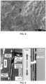
- the broken composite exhibits a large population of fiber "pull-outs" and "rabbit holes” on a cracked matrix background that is relatively smooth as shown in Fig. 10 , showing fractography of a SiCf-SiC CMC fracture surfaces with a BN interphase on Hi-Nicalon SiC fibers and PIP infiltrated matrix [a12].
- the fracture exhibits a pattern of fiber pullouts and "rabbit holes" expected with matrix macrocracking.
- the interphase provides a means to diffuse strain energy that increases the tensile strength by a factor of 2-3 and increases the strain to rupture fifty-fold over monolithic ceramics.
- Droillard et al. [a10] showed that there was still room for a further 50% improvement in tensile strength. They identified the critical importance of ⁇ crack propagation remaining within the interphase layer (as in Fig. 11 ) as opposed to reaching the fiber's surface (as in Fig. 9 ).
- Fig. 11 is an illustration of the effect of a strong adhesion of the innermost layer of the interphase to the fiber. A matrix ⁇ crack is deflected into the outermost PyC layer of the interphase, until the next SiC layer cracks in tension, letting the crack propagate further in shear. The crack propagation continues until it reaches the innermost PyC layer and keeps propagating in it (from [a10]).
- Naslain et al. [a13] refer to the function of the interphase as a "[micro]mechanical fuse". This is indeed a good analogy in the sense that the main function of the interphase is to prevent any local overload of the matrix once a ⁇ crack develops in close proximity to a fiber. Interestingly, the thickness of interphase layers does not appear to matter with regard to their micromechanical behavior. Thick layers appear to behave the same as thin layers provided interface bonding are the same [a11].
- Fig. 12 provides a comparative summary of all interphase-mediated failure modes. Fig. 12 shows SiCf-SiC CMC tensile curves without interphase, with weakly bonded interphase, and strongly bonded interphase and corresponding fracture patterns (adapted from [a9] and [a10]).
- Droillard et al. [a10] applied an undisclosed proprietary treatment to the fiber.
- this treatment appears to be a de-sizing followed by chlorine-etching of the SiCf's surface [a15].
- this treatment produces some surface roughness on the fiber's surface, estimated to be between 100 and 150 nm on the basis of published pictures.
- fiber roughness can be adjusted to the desired RMS in production, thereby removing the need for chlorine etching and the fiber damage usually associated with this process [a16].
- a shear strength gradient along the interphase radius is accomplished by varying the degree of crystallization of BN or PyC, from fully crystallized to turbostratic as the radius increases. In the case of BN coatings, this idea will reveal its full potential in view of the thermodynamic implications discussed further below.
- Oxidation mechanisms and kinetics of Cf-SiC CMCs are disclosed by Naslain et al. [a17], from which can be extracted the schematics of crack-induced oxidation damage reproduced in Fig. 13 , an illustration of crack-induced oxidation damage in Cf-SiC CMC: (i) diffusion along the SiC-microcracks, (ii) diffusion in the pore created by oxidation of carbon phases, (iii) diffusion of oxygen at carbon surface to reaction sites, (iv) surface reaction, (v) growth of silica on SiC-microcrack wall. Reproduced from [a17].
- FIG. 13 is concerned with carbon fiber reinforced CMC, this picture points out the most critical issue in relation to high-density microcracking: The larger the crack population, the greater the risks of oxidation damage. Hence the price to pay for a greater composite strength would appear to be a greater propensity to oxidation damage.
- the present invention proposes a nanocoating architecture which can reverse this propensity the same way local immune responses defend against foreign intrusions throughout the body.
- SiC can be the principal barrier against oxidation. SiC oxidation initially proceeds from depletion of Carbon (released as CO or CO 2 gas) and, assuming oxidation is complete, the formation of an SiO 2 layer, which remains solid up to 1600°C (near the melting point of Silica). Deal and Grove [a21]. For CMCs, surface oxidation also confers some self-healing properties due in large part to the molar volume of Silicon being more than doubled upon oxidation ([a13] & Fig. 13 ). Once a solid SiO 2 shield is formed, oxidation proceeds by diffusion of ionic oxygen into SiO 2 and diffusion of CO out of it. The oxidation process is therefore mass transport limited, and the oxide layer thickness typically increases as the square root of exposure time. Only if oxidation is incomplete, as is the case at high temperature and low oxygen partial pressure does the reaction become rate limited, depleting Silicon linearly with time as volatile silicon sub-oxide (SiO(g)) [a19][a20].
- Fully crystallized graphite is thermally stable to 3650°C but starts to oxidize at 400°C in air. It exhibits a temperature dependent anisotropic oxidation, which progresses much faster along the edges of the basal planes than across at low temperature [a25]. As temperature increases normal etching catches up to in-plane to equalize in the 750-800°C range. PyC being a turbostratic graphite, it exhibits a high level of nanoporosity, hence a greater reactivity to oxygen. Delcamp et al.
- hBN has become the interphase material of choice for high-temperature SiCf-SiC CMC in oxidizing environments.
- hBN has high thermal conductivity even at elevated temperature (600 and 30 W/m K intralaminar and perpendicular respectively), high electrical resistivity, and high level of chemical inertness.
- elevated temperature 600 and 30 W/m K intralaminar and perpendicular respectively
- electrical resistivity high level of chemical inertness.
- hBN is believed to sublimate and decompose at ⁇ 3000°C at 100 kPa, although there is indication that it can be melted at atmospheric pressure under a pure nitrogen atmosphere [a26].
- Liquid Boria has many attractive properties in the context of CMCs: It has a very low vapor pressure ( ⁇ 0 Pa at 20°C rising to 1.5 kPa at 1200°C [a28]), it is an extremely viscous fluid (480 Pa s @ 600°C [a29] rising to -160 10 3 Pa s near its freezing point), and it diffuses readily in Silica to form Borosilicate glass (a.k.a Pyrex TM ) which exhibits the highest silicate glass transition temperature.
- Borosilicate glass a.k.a Pyrex TM
- Boria or Borosilicate if in solution
- oxidation of hBN is greatly accelerated in the presence of water vapor, especially in low concentration ( ⁇ 20 ppm) [a17][a24][a30-32].
- Fully crystallized hBN synthesis requires an elevated temperature of about 2000°C.
- CVD temperature approaches 2000°C
- the deposited BN approaches full density and stoichiometry.
- stoichiometry appears to be achieved in the range 1800-2000°C.
- Deposit density also appears to be very sensitive to precursor pressure.
- BN deposited below 1300 Pa at temperature between 1400 and 2000°C is fully dense.
- BN density has a large influence on oxidation resistance, even in the presence of moisture.
- the thermogravimetric analysis reported by Matsuda [a32] shows that BN deposited at 650 Pa between 1400 and 2000°C -fully crystallized hBN- is essentially stable at temperatures up to 800°C.
- the influence of oxygen on the crystallization of tBN presents a particularly attractive property.
- Boria B 2 O 3
- the present invention pertains to a system of nano-coatings for High Performance Fibers (HPFs), which: (1) optimizes the toughness of a ceramic matrix composite, and (2) endows a ceramic matrix composite material with a reaction to oxidation damage that is akin to an immune response by mobilizing resources locally to combat oxygen ingress and build up protection against further oxidation
- HPFs High Performance Fibers
- the first two attributes are attained in accordance with the present invention by providing a BN layer with a crystallization gradient, from fully crystallized hBN on the innermost radius, to tBN on the outermost one. This can also be attained with carbon instead of BN, from fully crystallized graphitic innermost, to PyC outermost.
- hBN is particularly vulnerable to oxidation along the edges of its basal planes, and tBN even more so, which makes it a de-facto oxygen nanosensor. These edges would be exposed at the ends of the CMC, where the fibers' ends surface out of the matrix, and in case the event of surface ⁇ cracking. Hence to minimize the effect of oxygen ingress, we would need to minimize the thickness of BN layers consistent with the shear and fiber roughness requirements.
- successive nanocoatings e.g., 25 to 50 nm thick are provided, such that the innermost layer comprises fully crystallized hBN, and the outermost is tBN, can serve to promote matrix ⁇ cracking over macrocracking while providing a built-in defense mechanism against oxidation damage.
- the ⁇ cracking behavior increases the composite toughness while the proposed interphase system counters the vulnerability to oxygen. Should a surface ⁇ crack develop, letting oxygen diffuse in, the outer layer of exposed tBN will convert to hBN under the influence of Boria.
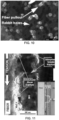
- Fig. 14 summarizes this projected scenario for the proposed CMC's immune response.
- Fig. 14 shows an exemplary response of the proposed immune system function.
- B, C Increasing magnification of a surface matrix ⁇ crack.
- D The interphase before exposure to Oxygen consists of a layer of hBN with an overcoat of tBN.
- E Upon exposure to Oxygen, the fraction of Boron oxide created acts as a catalyst to locally transform tBN into hBN, causing the oxidation temperature to rise by 400°C and subdividing the un-cracked section into a mini-composite homomorphic to the original. Meanwhile the crack tends to fill with SilicateBorosilicate glass.
- the present invention will be of interest to all parties with a vested interest in high-temperature structural components.
- this includes all internal combustion engines, with a specific near term and pressing interest in jet engines and turbine power generation.
- the key US primes are aviation and other high performance engine manufacturers.
- Other major anticipated markets include the nuclear industry where advanced Ceramic Matrix Composite have been identified as a safer (though currently more expensive) alternative to Zircalloy for fuel rods and boxes. (SiC-SiC Ceramic Matrix Composites may have been able to withstand damages and survive the events of Fukishima.)
- the present invention in one aspect is a high performance fiber (HPF) structure, including a plurality of fibers arranged in the structure; a matrix disposed between the fibers; wherein a multilayer coating is provided along the surfaces of at least some of the fibers.
- the multilayer coating includes: an inner layer region having a sheet-like strength; and an outer layer region, having a particle-like strength, such that any cracks propagating toward the outer layer from the matrix propagate along the outer layer and back into the matrix, thereby preventing the cracks from approaching the fibers.
- Fibers may be aligned with multiple orientations, e.g., one layer longitudinal, next layer across, alternatively, fibers can be woven in a 2-d pattern or braided in a 3-D "brick.”
- the inner layer region may comprise graphitic carbon and the outer layer region may comprise pyrolytic carbon; or the inner layer region may comprise hexagonal B-nitride, and the outer layer region may comprise turbostatic B-nitride.
- the structure induces a high-density microcracking effect within the matrix, substantially insulating the fiber from propagating cracks, and increasing toughness.
- the inner layer region acts as an oxygen barrier for the fiber, and wherein, upon exposure to oxygen, at least a portion of the outer layer region converts into an oxygen barrier similar to the inner layer region, thereby providing greater protection to the fiber.
- Unique features include: (1) a nanocoating system that locally diverts matrix microcracks within the coating layer and forces them to progress along the fiber thereby displacing stress in the matrix until such time as it cracks again and the cycle starts anew. (2) One type of nanocoating system, when exposed to oxygen at high temperature will convert to another type, thus locally mobilizing resources against oxidation damage in a manner akin to a biological entity's immune system.
- Nanocoating system maximizes energy absorption capacity of Ceramic Matrix Composite by inducing engineered high-density microcracking of the matrix, thereby increasing toughness and strain to failure.
- SecondNanocoating system offers not just self-healing, but also builds up further defense against oxidation damage. Structure between microcracks is homomorphic to original composites with scar tissue in between. This provides a CMC with higher resistance when operating at high temperature under oxidizing environments.
- HPFs High Performance Fibers
- ceramic matrix composite materials are being proposed for expanding uses in many specialized applications, such as military and aerospace (turbo machinery, rockets, advanced structures), automobile, biomedical, energy, and other applications that require advanced materials with exceptional strength, stiffness, heat resistance, and/or chemical resistance.
- HPFs are sought when a combination of extreme material properties is required which cannot be met by existing metal filaments or by carbon, glass, vegetal or mineral fibers.
- HPF systems generally include a plurality of coated fibers, spaced within a "matrix.”
- Silicon Carbide fiber (SiCf) reinforced Silicon Carbide matrix (SiCm) composites may have a layer of interphase material between the fibers and the matrix.
- One layer material may be Boron Nitride (BN) in turbostratic (tBN) or fully crystallized hexagonal form (hBN).
- BN Boron Nitride
- tBN turbostratic
- hBN fully crystallized hexagonal form
- the required interphase coating may be applied to the fiber once they have been preformed, de-sized, and are ready to be infiltrated. This method however results in contact between fibers that results in diffusion welds, known as fiber "bridges," that significantly reduce the mechanical toughness of the resulting composite.
- the present disclosure modifies the process to prevent bridging by ensuring the fibers are not in contact during the coating process.
- the resulting composite material properties are therefore improved by eliminating weak points in the fiber's load carrying structure.
- SiCf-SiC composite materials are designed to be load-bearing and oxidation resistant at high temperature. Although the constitutive ceramics are brittle by nature the composite exhibits strength and toughness as a result of micromechanical engineering of the structure, which diverts overloads and stress concentration in order to improve energy absorption. This may be accomplished by the material located between fibers and matrix, called the interphase.
- This interphase may play the role of a micromechanical fuse that shears along the fiber to prevent fracture of the matrix. To be able to effectively fulfill its function however, the interphase should be continuous along the fiber. Current manufacturing technology cannot obtain this continuity because fibers are in direct contact. Short of pre-coated SiCf being available, the next best solution is to prevent fiber contact during coating. This is what the present disclosure achieves, thereby promoting mechanical properties of the composite.
- Hyper-Therm HTC (Huntington Beach, CA), for example, has built a business out of coating fabrics and preforms.
- Fig. 15 is extracted from a company prospectus [b1].
- Fig. 15 shows successive enlargements of multilayer in-situ coatings of SiC fibers (Source: Hyper-Therm HTC [b1]). It illustrates the extraordinar level of control that Hyper-Therm has been able to achieve with multilayer coatings.
- What this picture also illustrates, however, are points of fiber-to-fiber contacts that are a direct result of in-situ coating, where de-sized fibers are allowed to come into direct contact and subsequently bond during the coating process or in high temperature use. Such points are identified with yellow circles in Fig.
- the resulting carbon coating appears fairly uniform. However, closer examination showed them to be nanoporous (pore size ⁇ 2 nm). Subsequent thermogravimetric analysis showed that this porosity causes the carbon to oxidize at much lower temperatures than fully crystallized carbon: 225°C vs. 400°C for graphite.
- Fig. 18 a high resolution SEM of a polished cross-section showing the remaining layer of nanoporous carbon with an overlay of Al-ON.
- Source: [b3] the resulting CMC structure appears to be very close to the fictitious SEM of the desired coating in Fig. 16 .
- close examination of fracture surfaces along the fibers' axis reveals an incomplete coverage that the authors attribute to incomplete impregnation by the AlCl 3 solution -
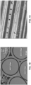
- Fig. 19 is a view of the same CMC microstructure along a fracture surface parallel to the fibers showing incomplete coverage of the coating.
- Wesson [b5] independently concurs based on experience with trying to spool un-sized carbon fiber tows. A fraction of un-sized filaments tend to break during spooling, back-winding and catching incoming tow, eventually forming a solid block of tangled filaments that Wesson characterizes as a "brick."
- a coating step is to be effected by a diffusion driven process such as CVD on a fiber tow, it must happen before filaments are focused into a tow, sized, and spooled. De-sizing, or spreading a SiCf tow appear to cause so much process induced damages that they are impractical.
- the original analysis of the tribological behavior of SiCf presented next is supportive of the experimental findings reported by Wesson [b5].
- Hopfe et al. [b9] promotes the use of LCVD to coat fibers. Hopfe et al. assume however that the tow is spread into a plane ribbon prior to entering the CVD reactor. None is mentioned however as to how the tow would be placed in such a configuration.
- In-situ coating is usually the last process step applied to fibers, just prior to matrix infiltration. This order is rendered necessary by the extreme tribological properties of SiC fibers and may result in fibers being in direct contact with each other prior to interphase coating. The result is that fibers may fuse or bond together at such contact points during coating, matrix infiltration, or during use, forming "bridges" that become weak points of the resulting ceramic matrix composite material.
- the present disclosure modifies the in-situ coating process by adding a selective removal (e.g., etch) of Silicon from SiC on the surface of the fiber, and then replacing the remaining nanoporous carbon layer with an interphase layer (e.g., Boron Nitride), that coats and separates the fibers, thus preventing bridging.
- a selective removal e.g., etch
- an interphase layer e.g., Boron Nitride
- the present disclosure in one aspect is a method of forming an interphase in a ceramic matrix composite material having a plurality of SiC fibers, which maximizes toughness by minimizing fiber to fiber contact, including arranging a plurality of SiC fibers into a preform; selectively removing (e.g., etching) silicon out of the surface of the fibers resulting in a porous carbon layer on the fibers; and replacing the porous carbon layer with an interphase layer (e.g., Boron Nitride), which coats the fibers to thereby minimize fiber to fiber contact in the preform.
- an interphase layer e.g., Boron Nitride
- the interphase layer may comprise Boron Nitride, in which case the method may include infiltrating the preform with Boric Acid; and reacting the Boric Acid with the carbon and an N-yielding compound to form the Boron Nitride layer.
- the method further includes infiltrating the preform with matrix material, resulting in a ceramic matrix composite material.
- the Hertzian ellipsoid contact theory [b14] allows an estimate of the maximum contact pressure where the fibers are in contact. For example, under a load as minute as 1 mN and for a crossing angle of 30°, the maximum contact pressure is already 2.2 GPa with a contact area less than a square micron.
- Fig. 22 shows maximum contact pressure (GPa) and contact area ( ⁇ m 2 ) as a function of the ⁇ m crossing angle for pairs of 15 SiC and C filaments under a load of 1 mN.
- Fig. 22 expands this example and plots the maximum contact pressure and contact area for crossing angles ranging from 10° to 90°. If it is further assumed that the fiber contact is sliding at the modest speed of 1 cm/s, then the maximum areal power dissipated at the fiber contact is 13 MW/m 2 .
- Fig. 22 also offers an objective comparison to carbon on carbon.
- the same derivations for identical load and filament geometry show that for Carbon, the contact pressure is one order of magnitude smaller and the contact area is three times larger compared to SiC fibers under the same conditions.
- the areal power dissipated under identical sliding conditions drops to 200 kW/m 2 - a reduction by five orders of magnitude.
- Such a huge difference between the two materials is rather startling, especially considering that the Carbon fibers' Young's modulus is of the same order as that of current SiC fibers ( ⁇ 300 GPa). This difference can however be explained by the extraordinary forgiving nature of crystallized graphite and its extremely low coefficient of friction.
- SiCf are "sized” -usually with Poly Vinyl Alcohol (PVA)- right after the spinning process.
- PVA Poly Vinyl Alcohol
- the sizing agent envelops fibers with a protective soft material sheath that prevents direct fiber-to-fiber contact and promotes fiber sliding. Without it, SiCf tows could not be processed using textile equipment, could not be woven, or pre-formed.
- the coating was found to be mostly amorphous Boron Nitride, about 200 nm thick, with remaining Boron Oxide, which the authors attribute to (EQ. 1) being the rate limiting step.
- Shen et al. [b4] report relative losses of tensile strengths of 15-85% for Nicalon and C-Nicalon SiCf respectively.
- Fig. 23 shows the effect of SiCf exposure to BF3 (left) and HF diluted in Ar (right) [b17].
- the main advantage of carbon substitution for in-situ coating is to prevent fiber bridging. Wherever SiCf are in contact in a preform, selective etching of Silicon will result in a carbon layer separating the non-etched SiC core of the fiber.
- the present invention improves in-situ coating of Silicon Carbide fibers with Boron Nitride in Ceramic Matrix Composite applications.
- Current in-situ coating technology is constrained by the lack of availability of pre-coated fibers. Therefore coating is applied to the fibers after they have been woven, braided, or otherwise preformed. After de-sizing, areas of the fibers that are in close contact may fuse with high-temperature processing or use. This causes what is known as "bridging" and results in lower toughness properties for the composite.
- the present invention prevents bridging by creating a separation between fibers that is then filled with a suitable interphase material, in one exemplary case, Boron Nitride.
- a suitable interphase material in one exemplary case, Boron Nitride.
- the process steps required to attain this object consist of first creating a thin layer of nanoporous carbon out of the fiber's very own material, and then substituting or replacing the carbon by an appropriate method. This process may be implemented as follows:
- the layer of Boron Nitride does not need to be thick. In fact, a layer of 25 nm should be sufficient if the deposited BN is turbostratic, twice that if BN is fully crystallized hexagonal BN.
- the thin layer objective is aided by the fact that the starting carbon layer is nanoporous.
- the carbothermal reduction results in a reduction of the molar volume to 70% of its original size.
- the nitridation step causes an increase in molar volume to 166% the original size, which densifies the coating layer.
- Nanoporosity of the starting carbon coating will also favor the growth of turbostratic BN at temperatures below 2000°C. Above this temperature, turbostratic fully crystallizes to hexagonal BN.
- Addition of the matrix material is then performed, resulting in a tough, ceramic matrix composite material.
- the present disclosure is in one aspect a method of forming an interphase in a ceramic matrix composite material having a plurality of SiC fibers, which maximizes toughness by minimizing fiber to fiber bridging, including arranging a plurality of SiC fibers into a preform; selectively removing (e.g., etching) silicon out of the surface of the fibers resulting in a porous carbon layer on the fibers; and replacing the porous carbon layer with an interphase layer (e.g., Boron Nitride), which coats the fibers to thereby minimize fiber to fiber bridging in the preform.
- an interphase layer e.g., Boron Nitride
- the interphase layer may comprise Boron Nitride, in which case the method may include infiltrating the preform with boric acid; and reacting the Boric Acid with the carbon and an N-yielding compound to form the Boron Nitride layer.
- the method further includes infiltrating the preform with matrix material, resulting in a ceramic matrix composite material.
- a ceramic matrix composite material is formed having a plurality of SiC fibers, by performing a selective removal of Silicon from SiC on the surface of the fibers resulting in a porous carbon layer, and replacing the remaining porous carbon layer with an interphase layer, which coats the fibers, thus preventing fiber bridging prior to infiltration of a matrix material.
- the present disclosure will be of interest to all parties with an interest in high-temperature structural components, with the exception of nuclear applications for which the use of Boron is counter-indicated.
- this includes all internal combustion engines, with a specific near term and pressing interest in jet engines and turbine power generation.
- This disclosure is expected to find an important place in all high and ultra-temperature applications such as rocket nozzles, hypersonic domes, jet engines, power generation, high-efficiency internal combustion engines, and armor applications.
- Anticipated impact is economic: Improved performance, more affordable SiC-SiC composite materials.
Landscapes
- Chemical & Material Sciences (AREA)
- Engineering & Computer Science (AREA)
- Ceramic Engineering (AREA)
- Manufacturing & Machinery (AREA)
- Organic Chemistry (AREA)
- Materials Engineering (AREA)
- Structural Engineering (AREA)
- Inorganic Chemistry (AREA)
- Chemical Kinetics & Catalysis (AREA)
- General Chemical & Material Sciences (AREA)
- Textile Engineering (AREA)
- Chemical Or Physical Treatment Of Fibers (AREA)
- Inorganic Fibers (AREA)
- Chemical Vapour Deposition (AREA)
- Ceramic Products (AREA)
- Manufacture, Treatment Of Glass Fibers (AREA)
Claims (8)
- Hochleistungsfaser (HPF)-Struktur, umfassend:eine Vielzahl von Fasern, die in der Struktur angeordnet sind;eine Matrix, die sich zwischen den Fasern befindet;wobei ein mehrschichtiger Überzug entlang der Oberflächen von zumindest einigen der Fasern vorgesehen ist, wobei der mehrschichtige Überzug aufweist:einen inneren Schichtbereich mit einer blattartigen Festigkeit;einen äußeren Schichtbereich mit einer partikelartigen Festigkeit, so dass sich alle Risse, die sich von der Matrix in Richtung der äußeren Schicht ausbreiten, entlang des äußeren Schichtbereichs und zurück in die Matrix ausbreiten, wodurch verhindert wird, dass sich die Risse den Fasern nähern,dadurch gekennzeichnet, dass der mehrschichtige Überzug einen Scherfestigkeitsgradienten entlang des Interphasenradius hat, der dadurch erzielt wird, dass der Kristallisationsgrad von Bornitrid (BN) oder pyrolytischem Kohlenstoff (PyC) von vollständig kristallisiert bis turbostratisch variiert, wenn der Interphasenradius vom inneren Schichtbereich zum äußeren Schichtbereich zunimmt,wobei der innere Schichtbereich Graphit-Kohlenstoff umfasst und der äußere Schichtbereich pyrolytischen Kohlenstoff umfasst, und/oderwobei der innere Schichtbereich hexagonales Bornitrid umfasst und der äußere Schichtbereich turbostratisches Bornitrid umfasst.
- Struktur nach Anspruch 1, wobei die Struktur einen hochdichten Mikroriss-Effekt innerhalb der Matrix induziert, der die Faser im Wesentlichen davor schützt, dass Risse sich ausbreiten.
- Struktur nach einem der vorhergehenden Ansprüche, wobei der innere Schichtbereich als Sauerstoffbarriere für die Faser wirkt.
- Struktur nach Anspruch 3, wobei sich bei einer Einwirkung von Sauerstoff zumindest ein Teil des äußeren Schichtbereichs in eine Sauerstoffbarriere ähnlich dem inneren Schichtbereich umwandelt, wodurch ein größerer Schutz für die Faser bereitgestellt wird.
- Verfahren zum Bilden einer Hochleistungsfaser (HPF)-Struktur, umfassend:Bereitstellen einer Vielzahl von Fasern, die in der Struktur angeordnet sind;Bereitstellen einer Matrix, die sich zwischen den Fasern befindet;Bereitstellen eines mehrschichtigen Überzugs entlang der Oberflächen von zumindest einigen der Fasern, wobei der mehrschichtige Überzug aufweist:einen inneren Schichtbereich mit einer blattartigen Festigkeit; einen äußeren Schichtbereich mit einer partikelartigen Festigkeit,gekennzeichnet durchErzeugen eines Scherfestigkeitsgradienten in dem mehrschichtigen Überzug entlang des Interphasenradius dadurch, dass der Kristallisationsgrad von Bornitrid (BN) oder pyrolytischem Kohlenstoff (PyC) von vollständig kristallisiert bis turbostratisch variiert, wenn der Interphasenradius vom inneren Schichtbereich zum äußeren Schichtbereich zunimmt, so dass ein Riss, der sich von der Matrix in Richtung der äußeren Schicht ausbreitet, entlang des äußeren Schichtbereichs und zurück in die Matrix ausbreitet, wodurch verhindert wird, dass sich die Risse den Fasern nähern,wobei der innere Schichtbereich Graphit-Kohlenstoff umfasst und der äußere Schichtbereich pyrolytischen Kohlenstoff umfasst, und/oderwobei der innere Schichtbereich hexagonales B-Nitrid umfasst und der äußere Schichtbereich turbostratisches B-Nitrid umfasst.
- Verfahren nach Anspruch 5, wobei die Struktur einen hochdichten Mikroriss-Effekt innerhalb der Matrix induziert, der die Faser im Wesentlichen davor schützt, dass Risse sich ausbreiten.
- Verfahren nach Anspruch 6, wobei der innere Schichtbereich so ausgebildet ist, dass er als Sauerstoffbarriere für die Faser wirkt.
- Verfahren nach Anspruch 7, wobei sich mindestens ein Teil des äußeren Schichtbereichs bei Einwirkung von Sauerstoff in eine Sauerstoffbarriere umwandelt, die dem inneren Schichtbereich ähnlich ist, wodurch ein größerer Schutz für die Faser bereitgestellt wird.
Applications Claiming Priority (5)
| Application Number | Priority Date | Filing Date | Title |
|---|---|---|---|
| US201261588765P | 2012-01-20 | 2012-01-20 | |
| US201261588733P | 2012-01-20 | 2012-01-20 | |
| US201261588788P | 2012-01-20 | 2012-01-20 | |
| PCT/US2013/022053 WO2013180764A1 (en) | 2012-01-20 | 2013-01-18 | High strength ceramic fibers and methods of fabrication |
| EP13796908.5A EP2804969B1 (de) | 2012-01-20 | 2013-01-18 | Herstellungsverfahren fur hochfeste keramische fasern |
Related Parent Applications (1)
| Application Number | Title | Priority Date | Filing Date |
|---|---|---|---|
| EP13796908.5A Division EP2804969B1 (de) | 2012-01-20 | 2013-01-18 | Herstellungsverfahren fur hochfeste keramische fasern |
Publications (3)
| Publication Number | Publication Date |
|---|---|
| EP3744877A2 EP3744877A2 (de) | 2020-12-02 |
| EP3744877A3 EP3744877A3 (de) | 2021-02-17 |
| EP3744877B1 true EP3744877B1 (de) | 2024-11-13 |
Family
ID=49673789
Family Applications (2)
| Application Number | Title | Priority Date | Filing Date |
|---|---|---|---|
| EP20167062.7A Active EP3744877B1 (de) | 2012-01-20 | 2013-01-18 | Hochfeste keramische fasern und deren herstellungsverfahren |
| EP13796908.5A Active EP2804969B1 (de) | 2012-01-20 | 2013-01-18 | Herstellungsverfahren fur hochfeste keramische fasern |
Family Applications After (1)
| Application Number | Title | Priority Date | Filing Date |
|---|---|---|---|
| EP13796908.5A Active EP2804969B1 (de) | 2012-01-20 | 2013-01-18 | Herstellungsverfahren fur hochfeste keramische fasern |
Country Status (5)
| Country | Link |
|---|---|
| US (3) | US10047015B2 (de) |
| EP (2) | EP3744877B1 (de) |
| JP (3) | JP6353368B2 (de) |
| CN (1) | CN104204315B (de) |
| WO (1) | WO2013180764A1 (de) |
Families Citing this family (40)
| Publication number | Priority date | Publication date | Assignee | Title |
|---|---|---|---|---|
| US10954167B1 (en) * | 2010-10-08 | 2021-03-23 | Advanced Ceramic Fibers, Llc | Methods for producing metal carbide materials |
| CN104204315B (zh) | 2012-01-20 | 2019-03-15 | 自由形态纤维有限公司 | 高强度陶瓷纤维及其制造方法 |
| WO2015112935A1 (en) | 2014-01-27 | 2015-07-30 | Free Form Fibers, Llc | Contiguously blended nano-scaled multi-phase fibers |
| US9732005B2 (en) * | 2014-04-07 | 2017-08-15 | United Technologies Corporation | Method of forming in-situ boron nitride for ceramic matrix composite environmental protection |
| JP6693891B2 (ja) * | 2014-06-23 | 2020-05-13 | フリー フォーム ファイバーズ リミテッド ライアビリティ カンパニー | 核燃料構造体及び核燃料構造体を作製する方法 |
| US11499230B2 (en) | 2014-08-18 | 2022-11-15 | Dynetics, Inc. | Method and apparatus for fabricating fibers and microstructures from disparate molar mass precursors |
| US10167555B2 (en) * | 2014-08-18 | 2019-01-01 | Dynetics, Inc. | Method and apparatus for fabricating fibers and microstructures from disparate molar mass precursors |
| US9938393B2 (en) * | 2015-01-23 | 2018-04-10 | Free Form Fibers, Llc | Radially graded fully dense inorganic filaments for enhanced strength and creep resistance |
| US9975815B2 (en) | 2015-02-26 | 2018-05-22 | General Electric Company | Methods for forming ceramic matrix composite articles |
| US10401028B2 (en) * | 2015-06-05 | 2019-09-03 | Rolls-Royce American Technologies, Inc. | Machinable CMC insert |
| EP3389847A1 (de) * | 2015-12-16 | 2018-10-24 | Basf Se | Reaktor zur durchführung von heterogen katalysierten gasphasenreaktionen sowie verwendung des reaktors |
| US12133465B2 (en) | 2016-05-11 | 2024-10-29 | Free Form Fibers, Llc | Multilayer functional fiber and method of making |
| JP2019529150A (ja) * | 2016-05-11 | 2019-10-17 | フリー フォーム ファイバーズ リミテッド ライアビリティ カンパニー | 繊維送達アセンブリおよびその製造方法 |
| US20170369998A1 (en) * | 2016-06-23 | 2017-12-28 | Free Form Fibers, Llc | Nanofiber-coated fiber and methods of making |
| WO2018064269A1 (en) * | 2016-09-28 | 2018-04-05 | Free Form Fibers, Llc | Refractory oxide coated fiber and method of making |
| CA3044401C (en) | 2016-11-29 | 2023-09-19 | Free Form Fibers, Llc | Fiber with elemental additive(s) and method of making |
| GB2553390B (en) | 2017-03-15 | 2020-01-15 | Rolls Royce Power Eng Plc | Method of manufacture |
| US10676391B2 (en) * | 2017-06-26 | 2020-06-09 | Free Form Fibers, Llc | High temperature glass-ceramic matrix with embedded reinforcement fibers |
| WO2019005911A1 (en) * | 2017-06-27 | 2019-01-03 | Free Form Fibers, Llc | HIGH PERFORMANCE FUNCTIONAL FIBROUS STRUCTURE |
| GB201714988D0 (en) * | 2017-09-18 | 2017-11-01 | M-Solv Ltd | Method of manufacturing a sensor, sensor, method of manufacturing a filter, filter, and method of manufacturing a porous material comprising a continuous meta |
| US10941491B2 (en) | 2017-09-25 | 2021-03-09 | Raytheon Technologies Corporation | Continuous multiple tow coating reactor |
| US10710111B2 (en) | 2017-09-25 | 2020-07-14 | Raytheon Technologies Corporation | Continuous tow fiber coating reactor |
| US12410107B2 (en) * | 2018-04-20 | 2025-09-09 | Rtx Corporation | Nanolaminate fiber interface coatings for composites |
| EP3947319A1 (de) * | 2019-04-05 | 2022-02-09 | Safran Ceramics | Verfahren zur herstellung eines aus cmc gefertigten teils |
| FR3101629B1 (fr) * | 2019-10-07 | 2022-06-17 | Safran Ceram | Procédé de fabrication d'une pièce en CMC |
| US12006605B2 (en) * | 2019-09-25 | 2024-06-11 | Free Form Fibers, Llc | Non-woven micro-trellis fabrics and composite or hybrid-composite materials reinforced therewith |
| US11149584B2 (en) * | 2019-10-07 | 2021-10-19 | General Electric Company | Containment case having ceramic coated fibers |
| US11981087B2 (en) | 2019-12-10 | 2024-05-14 | Hewlett-Packard Development Company, L.P. | Three-dimensional (3D) printed objects with fracture channels |
| US12415763B2 (en) | 2020-01-27 | 2025-09-16 | Free Form Fibers, Llc | High purity ingot for wafer production |
| US12312682B2 (en) | 2020-01-27 | 2025-05-27 | Free Form Fibers, Llc | High purity fiber feedstock for loose grain production |
| JP2021127531A (ja) * | 2020-02-12 | 2021-09-02 | 日本特殊陶業株式会社 | 複合繊維 |
| CN111269017B (zh) * | 2020-03-02 | 2021-12-21 | 宜兴市海科耐火材料制品有限公司 | 危废气化熔融炉专用耐高温抗侵蚀内衬材料及其制备方法 |
| US11761085B2 (en) | 2020-08-31 | 2023-09-19 | Free Form Fibers, Llc | Composite tape with LCVD-formed additive material in constituent layer(s) |
| EP4359363A4 (de) | 2021-06-21 | 2025-05-07 | Free Form Fibers, LLC | Faserstrukturen mit eingebetteten sensoren |
| EP4363630A4 (de) | 2021-06-29 | 2025-07-09 | Free Form Fibers Llc | Chemische dampfabscheidung (ewcvd) mit eingebettetem draht |
| US12264110B2 (en) * | 2021-07-21 | 2025-04-01 | General Electric Company | System and method for coating ceramic fiber |
| CN116288802B (zh) * | 2023-04-03 | 2025-03-14 | 清华大学深圳国际研究生院 | 一种氮化硼-芳纶复合同轴纤维及其制备方法 |
| JP2025080034A (ja) * | 2023-11-13 | 2025-05-23 | 三菱重工航空エンジン株式会社 | Bn被覆セラミックス繊維、それを備えたセラミックス基複合材料、ならびにbn被覆セラミックス繊維の製造方法 |
| CN118109782B (zh) * | 2024-04-23 | 2024-09-20 | 深圳市奥美特纳米科技有限公司 | 一种耐冲击高强度复合陶瓷涂层及其制备方法 |
| WO2025235880A1 (en) * | 2024-05-10 | 2025-11-13 | Rtx Corporation | Interfacial coatings |
Family Cites Families (96)
| Publication number | Priority date | Publication date | Assignee | Title |
|---|---|---|---|---|
| US3062683A (en) | 1959-07-23 | 1962-11-06 | Minnesota Mining & Mfg | Fiber-reinforced pressure-sensitive adhesives and tapes |
| US3148102A (en) | 1960-08-24 | 1964-09-08 | Debell & Richardson Inc | Method for the manufacture of multifilament glass tapes |
| US3755061A (en) | 1970-10-12 | 1973-08-28 | Minnesota Mining & Mfg | Prepreg tape |
| FR2116668A5 (de) | 1970-12-01 | 1972-07-21 | Rhodiaceta | |
| US4076380A (en) | 1976-10-28 | 1978-02-28 | Bell Telephone Laboratories, Incorporated | Graded index optical fiber |
| JPS5941510B2 (ja) | 1979-07-24 | 1984-10-08 | 双葉電子工業株式会社 | 酸化ベリリウム膜とその形成方法 |
| US4588699A (en) | 1983-03-17 | 1986-05-13 | United Technologies Corporation | High strength, thermally stable magnesium aluminosilicate glass-ceramic matrix-sic fiber composites |
| US4539248A (en) | 1984-09-18 | 1985-09-03 | Anchor Continental | Reinforced filament tape |
| JPS61132628A (ja) * | 1984-11-27 | 1986-06-20 | Inoue Japax Res Inc | グラフアイトのフアイバ−の製造法 |
| US4962070A (en) | 1985-10-31 | 1990-10-09 | Sullivan Thomas M | Non-porous metal-oxide coated carbonaceous fibers and applications in ceramic matrices |
| EP0318506A4 (en) * | 1986-08-18 | 1992-02-26 | Ceramic Research, Inc. | Laser assisted fiber growth |
| US5399430A (en) | 1986-08-18 | 1995-03-21 | Clemson University | Boron fibers having improved tensile strength |
| US5015540A (en) * | 1987-06-01 | 1991-05-14 | General Electric Company | Fiber-containing composite |
| FR2640258B1 (fr) * | 1988-05-10 | 1991-06-07 | Europ Propulsion | Procede de fabrication de materiaux composites a renfort en fibres de carbure de silicium et a matrice ceramique |
| FR2641776B1 (fr) * | 1989-01-13 | 1993-03-26 | Europ Propulsion | Materiau composite a interphases multiples entre fibres de renfort refractaires et matrice ceramique |
| JPH03131507A (ja) * | 1989-10-18 | 1991-06-05 | Sumitomo Metal Mining Co Ltd | 熱分解窒化ホウ素成形体及びその製造方法 |
| US5096739A (en) | 1989-11-27 | 1992-03-17 | The University Of Connecticut | Ultrafine fiber composites and method of making the same |
| JPH03285877A (ja) * | 1990-03-31 | 1991-12-17 | Tonen Corp | 繊維強化セラミックス複合材料及び強化用繊維 |
| DE4018940C2 (de) | 1990-06-13 | 2001-07-05 | Fraunhofer Ges Forschung | Vorrichtung zum kontinuierlichen gleichmäßigen Überziehen von Endlosfaserbündeln und Verwendung dieser Vorrichtung zum kontinuierlichen, gleichmäßigen Überziehen von Endlosfaserbündeln |
| US5133993A (en) * | 1990-08-20 | 1992-07-28 | General Atomics | Fiber-reinforced refractory composites |
| US5110771A (en) * | 1991-03-13 | 1992-05-05 | Northrop Corporation | Method of forming a precracked fiber coating for toughening ceramic fiber-matrix composites |
| GB9122997D0 (en) | 1991-10-30 | 1991-12-18 | Curran Dennis J G | Ceramic fibres |
| US5296288A (en) | 1992-04-09 | 1994-03-22 | The United States Of America As Represented By The Administrator Of The National Aeronautics And Space Administration | Protective coating for ceramic materials |
| US5309543A (en) | 1992-11-23 | 1994-05-03 | Ceramoptec, Inc. | Method of making infrared crystalline fiber and product |
| AU6082394A (en) | 1993-01-11 | 1994-08-15 | E.I. Du Pont De Nemours And Company | Thermostructural composite articles and method for making same |
| US5455106A (en) * | 1993-10-06 | 1995-10-03 | Hyper-Therm High Temperature Composites, Inc. | Multilayer fiber coating comprising alternate fugitive carbon and ceramic coating material for toughened ceramic composite materials |
| US5326731A (en) | 1993-11-18 | 1994-07-05 | Electrofuel Manufacturing Company | Ceramic compositions for wear resistant applications |
| JPH07252662A (ja) * | 1994-03-16 | 1995-10-03 | Hitachi Ltd | 高純度複合材およびその製法 |
| EP1209123A3 (de) * | 1995-09-08 | 2006-03-22 | William Marsh Rice University | Seile aus einwandigen Kohlenstoffnanoröhren |
| US6183714B1 (en) | 1995-09-08 | 2001-02-06 | Rice University | Method of making ropes of single-wall carbon nanotubes |
| US5786023A (en) | 1996-02-13 | 1998-07-28 | Maxwell; James L. | Method and apparatus for the freeform growth of three-dimensional structures using pressurized precursor flows and growth rate control |
| JPH09268065A (ja) | 1996-03-30 | 1997-10-14 | Toshiba Corp | 長繊維複合セラミックスおよびその製造方法 |
| US5955391A (en) * | 1996-03-29 | 1999-09-21 | Kabushiki Kaisha Toshiba | Ceramic matrix composite and method of manufacturing the same |
| JPH1045480A (ja) | 1996-07-31 | 1998-02-17 | Tonen Corp | 繊維強化複合材用無機質繊維を被覆するためのコーティング並びにこれを含む無機質繊維及び繊維強化複合材 |
| JPH1059780A (ja) * | 1996-08-20 | 1998-03-03 | Toshiba Corp | セラミックス基繊維複合材料およびその製造方法 |
| FR2756277B1 (fr) | 1996-11-28 | 1999-04-02 | Europ Propulsion | Materiau composite a matrice ceramique et renfort en fibres sic et procede pour sa fabrication |
| US6683783B1 (en) * | 1997-03-07 | 2004-01-27 | William Marsh Rice University | Carbon fibers formed from single-wall carbon nanotubes |
| JP2002515847A (ja) | 1997-05-29 | 2002-05-28 | ウィリアム・マーシュ・ライス・ユニバーシティ | 単層カーボンナノチューブ類から形成された炭素繊維類 |
| US6323413B1 (en) | 1998-04-22 | 2001-11-27 | Hv Technologies, Inc. | Microtubing with integral thermocouple |
| US6322889B1 (en) | 1998-04-23 | 2001-11-27 | The United States Of America As Represented By The United States Department Of Energy | Oxidation-resistant interfacial coating for fiber-reinforced ceramic |
| WO2000064808A1 (en) | 1999-04-07 | 2000-11-02 | Ucar Graph-Tech Inc. | Flexible graphite article and method of manufacture |
| US6979490B2 (en) * | 2001-01-16 | 2005-12-27 | Steffier Wayne S | Fiber-reinforced ceramic composite material comprising a matrix with a nanolayered microstructure |
| JP2002211980A (ja) | 2001-01-16 | 2002-07-31 | National Institute For Materials Science | SiC又はC繊維/SiC複合材料及びその製造方法 |
| JP4707854B2 (ja) * | 2001-03-08 | 2011-06-22 | 独立行政法人科学技術振興機構 | 高強度SiC繊維/SiC複合材料の製造方法 |
| JP4730495B2 (ja) * | 2001-05-25 | 2011-07-20 | イビデン株式会社 | 触媒コンバータ用保持シール材及びその製造方法、触媒コンバータ |
| GB0130608D0 (en) | 2001-12-21 | 2002-02-06 | Psimedica Ltd | Medical fibres and fabrics |
| US20050247904A1 (en) | 2002-04-27 | 2005-11-10 | The Regents Of The University Of Colorado | Nanocomposite ceramics of oxide and no-oxide phases and methods for producing same |
| US7019402B2 (en) | 2003-10-17 | 2006-03-28 | International Business Machines Corporation | Silicon chip carrier with through-vias using laser assisted chemical vapor deposition of conductor |
| JP2005231952A (ja) | 2004-02-20 | 2005-09-02 | Net Space:Kk | レーザ光によるカーボンナノチューブの合成 |
| US20050255033A1 (en) * | 2004-05-13 | 2005-11-17 | Yutaka Shimoji | Laser fabrication of continuous nanofibers |
| US20060039524A1 (en) | 2004-06-07 | 2006-02-23 | Herbert Feinroth | Multi-layered ceramic tube for fuel containment barrier and other applications in nuclear and fossil power plants |
| US7404983B1 (en) | 2004-08-04 | 2008-07-29 | The United States Of America, As Represented By The Secretary Of The Navy | Method and apparatus for open-air coating by laser-induced chemical vapor deposition |
| CN1733634A (zh) | 2004-08-11 | 2006-02-15 | 鸿富锦精密工业(深圳)有限公司 | 纳米线及其制备方法 |
| US7666475B2 (en) * | 2004-12-14 | 2010-02-23 | Siemens Energy, Inc. | Method for forming interphase layers in ceramic matrix composites |
| US7223465B2 (en) * | 2004-12-29 | 2007-05-29 | General Electric Company | SiC/SiC composites incorporating uncoated fibers to improve interlaminar strength |
| FR2890958B1 (fr) | 2005-09-16 | 2010-09-17 | Cit Alcatel | Preforme destinee a la fabrication d'une fibre optique comprenant des nanoparticules et procede de fabrication d'une fibre optique mettant en oeuvre une telle preforme |
| US20070093587A1 (en) | 2005-10-25 | 2007-04-26 | Starfire Systems | Silicon carbide precursors and uses thereof |
| US8288911B2 (en) | 2006-12-15 | 2012-10-16 | General Electric Company | Non-linear dielectrics used as electrical insulation for rotating electrical machinery |
| US20080153959A1 (en) | 2006-12-20 | 2008-06-26 | General Electric Company | Thermally Conducting and Electrically Insulating Moldable Compositions and Methods of Manufacture Thereof |
| WO2009018130A2 (en) | 2007-07-27 | 2009-02-05 | The Penn State Research Foundation | Piezoelectric materials based on flexoelectric charge separation and their fabrication |
| EP2196070B1 (de) | 2007-10-04 | 2017-01-25 | Lawrence Livermore National Security, LLC | Steuerung eines fusions (mit laserträgheitsverfeinerung) - und fissionskraftwerks |
| US8361566B2 (en) * | 2008-04-08 | 2013-01-29 | Los Alamos National Security, Llc | Method of fabrication of fibers, textiles and composite materials |
| US7910082B2 (en) | 2008-08-13 | 2011-03-22 | Corning Incorporated | Synthesis of ordered mesoporous carbon-silicon nanocomposites |
| FR2936088B1 (fr) | 2008-09-18 | 2011-01-07 | Commissariat Energie Atomique | Gaine de combustible nucleaire a haute conductivite thermique et son procede de fabrication. |
| US20100192535A1 (en) * | 2009-02-04 | 2010-08-05 | Smith Michael W | Boron nitride nanotube fibrils and yarns |
| US9217210B2 (en) | 2009-03-24 | 2015-12-22 | North Carolina State University | Process of making composite inorganic/polymer nanofibers |
| WO2011063422A1 (en) | 2009-11-23 | 2011-05-26 | Applied Nanostructured Solutions, Llc | Ceramic composite materials containing carbon nanotube-infused fiber materials and methods for production thereof |
| JP5889276B2 (ja) | 2010-04-06 | 2016-03-22 | エヌディーエスユー リサーチ ファウンデーション | 液体シラン系組成物およびシリコン系材料を生成するための方法 |
| KR101190202B1 (ko) | 2010-05-04 | 2012-10-12 | 한국과학기술연구원 | 에멀젼 전기 방사법을 이용한 탄화규소 나노섬유의 제조방법 및 이에 따라 제조된 탄화규소 나노섬유 |
| FR2961623B1 (fr) | 2010-06-16 | 2013-08-30 | Commissariat Energie Atomique | Joint d'interface solide a porosite ouverte pour crayon de combustible nucleaire et pour barre de commande nucleaire |
| US20120002777A1 (en) | 2010-06-30 | 2012-01-05 | Westinghouse Electric Company Llc | Triuranium disilicide nuclear fuel composition for use in light water reactors |
| US8491863B2 (en) * | 2010-09-28 | 2013-07-23 | Tsinghua University | Method for making carbon nanotube array |
| FR2965969A1 (fr) | 2010-10-07 | 2012-04-13 | Commissariat Energie Atomique | Aiguille de combustible nucleaire metallique comprenant une enveloppe avec des fibres de sic |
| US9206508B1 (en) | 2010-10-16 | 2015-12-08 | Alleppey V. Hariharan | Laser assisted chemical vapor deposition of silicon |
| WO2012091789A1 (en) | 2010-10-28 | 2012-07-05 | Massachusetts Institute Of Technology | Carbon-based nanostructure formation using large scale active growth structures |
| US8673120B2 (en) * | 2011-01-04 | 2014-03-18 | Jefferson Science Associates, Llc | Efficient boron nitride nanotube formation via combined laser-gas flow levitation |
| CN102647290B (zh) | 2011-02-17 | 2016-10-19 | 南京中兴软件有限责任公司 | 一种动态地址配置下网络连接保活的方法和装置 |
| WO2012129677A1 (en) | 2011-03-28 | 2012-10-04 | Torxx Group Inc. | Ceramic encapsulations for nuclear materials and systems and methods of production and use |
| US8574983B2 (en) | 2011-05-13 | 2013-11-05 | Intermolecular, Inc. | Method for fabricating a DRAM capacitor having increased thermal and chemical stability |
| US8932513B2 (en) | 2011-06-10 | 2015-01-13 | South Dakota Board Of Regents | Process of making titanium carbide (TiC) nano-fibrous felts |
| WO2012173960A1 (en) | 2011-06-13 | 2012-12-20 | University Of Dayton | Receptor-catalyst growth process for carbon nanotubes |
| US20130010915A1 (en) | 2011-07-08 | 2013-01-10 | Battelle Energy Alliance, Llc | Reactor fuel elements and related methods |
| CN104204315B (zh) | 2012-01-20 | 2019-03-15 | 自由形态纤维有限公司 | 高强度陶瓷纤维及其制造方法 |
| US9822470B2 (en) | 2012-12-14 | 2017-11-21 | Intel Corporation | Flexible embedded interconnects |
| WO2014143937A1 (en) | 2013-03-15 | 2014-09-18 | Liquidmetal Coatings, Llc | Fiber-containing composites |
| JP5696174B2 (ja) | 2013-04-26 | 2015-04-08 | イビデン株式会社 | 核燃料被覆管及びその製造方法 |
| CN103387230B (zh) | 2013-07-23 | 2015-12-23 | 中国科学院微电子研究所 | 一种石墨烯导电薄膜的制备方法 |
| WO2015112935A1 (en) * | 2014-01-27 | 2015-07-30 | Free Form Fibers, Llc | Contiguously blended nano-scaled multi-phase fibers |
| JP6693891B2 (ja) | 2014-06-23 | 2020-05-13 | フリー フォーム ファイバーズ リミテッド ライアビリティ カンパニー | 核燃料構造体及び核燃料構造体を作製する方法 |
| US9938393B2 (en) * | 2015-01-23 | 2018-04-10 | Free Form Fibers, Llc | Radially graded fully dense inorganic filaments for enhanced strength and creep resistance |
| JP2019529150A (ja) | 2016-05-11 | 2019-10-17 | フリー フォーム ファイバーズ リミテッド ライアビリティ カンパニー | 繊維送達アセンブリおよびその製造方法 |
| US12133465B2 (en) | 2016-05-11 | 2024-10-29 | Free Form Fibers, Llc | Multilayer functional fiber and method of making |
| US20170369998A1 (en) | 2016-06-23 | 2017-12-28 | Free Form Fibers, Llc | Nanofiber-coated fiber and methods of making |
| JP2019531418A (ja) | 2016-09-28 | 2019-10-31 | フリー フォーム ファイバーズ リミテッド ライアビリティ カンパニー | 耐火性添加剤を含む多組成繊維および製造方法 |
| WO2018064269A1 (en) | 2016-09-28 | 2018-04-05 | Free Form Fibers, Llc | Refractory oxide coated fiber and method of making |
| CA3044401C (en) | 2016-11-29 | 2023-09-19 | Free Form Fibers, Llc | Fiber with elemental additive(s) and method of making |
-
2013
- 2013-01-18 CN CN201380015183.8A patent/CN104204315B/zh active Active
- 2013-01-18 WO PCT/US2013/022053 patent/WO2013180764A1/en not_active Ceased
- 2013-01-18 JP JP2014553430A patent/JP6353368B2/ja active Active
- 2013-01-18 EP EP20167062.7A patent/EP3744877B1/de active Active
- 2013-01-18 EP EP13796908.5A patent/EP2804969B1/de active Active
- 2013-01-18 US US14/372,085 patent/US10047015B2/en active Active
-
2018
- 2018-06-08 JP JP2018110460A patent/JP6681944B2/ja active Active
- 2018-08-13 US US16/101,730 patent/US10882749B2/en active Active
- 2018-08-27 JP JP2018158218A patent/JP2019034884A/ja active Pending
-
2020
- 2020-11-02 US US17/087,092 patent/US20210253434A1/en not_active Abandoned
Non-Patent Citations (1)
| Title |
|---|
| LIANPING HOU ET AL: "1.55-/spl mu/m ridge DFB laser and electroabsorption Modulator integrated with buried-ridge-stripe dual-waveguide spot-size converter output", IEEE PHOTONICS TECHNOLOGY LETTERS, vol. 18, no. 1, 1 January 2006 (2006-01-01), pages 235 - 237, XP055210098, ISSN: 1041-1135, DOI: 10.1109/LPT.2005.862017 * |
Also Published As
| Publication number | Publication date |
|---|---|
| JP6353368B2 (ja) | 2018-07-04 |
| EP3744877A3 (de) | 2021-02-17 |
| JP6681944B2 (ja) | 2020-04-15 |
| US20150004393A1 (en) | 2015-01-01 |
| CN104204315B (zh) | 2019-03-15 |
| JP2018184695A (ja) | 2018-11-22 |
| JP2019034884A (ja) | 2019-03-07 |
| EP2804969A4 (de) | 2016-03-09 |
| EP2804969B1 (de) | 2020-04-01 |
| EP3744877A2 (de) | 2020-12-02 |
| CN104204315A (zh) | 2014-12-10 |
| US20210253434A1 (en) | 2021-08-19 |
| US10047015B2 (en) | 2018-08-14 |
| JP2015509152A (ja) | 2015-03-26 |
| WO2013180764A1 (en) | 2013-12-05 |
| EP2804969A1 (de) | 2014-11-26 |
| US10882749B2 (en) | 2021-01-05 |
| US20190062222A1 (en) | 2019-02-28 |
Similar Documents
| Publication | Publication Date | Title |
|---|---|---|
| US10882749B2 (en) | High strength ceramic fibers and methods of fabrication | |
| Chen et al. | Microstructure and mechanical properties of 3D Cf/SiBCN composites fabricated by polymer infiltration and pyrolysis | |
| Li et al. | Fabrication and Properties of 3‐DC f/SiC–ZrC Composites, Using ZrC Precursor and Polycarbosilane | |
| US11142483B2 (en) | Silicon carbide fiber reinforced silicon carbide composite material | |
| Wang et al. | KD-S SiCf/SiC composites with BN interface fabricated by polymer infiltration and pyrolysis process | |
| Huang et al. | Preparation and properties of the three-dimensional highly thermal conductive carbon/carbon-silicon carbide composite using the mesophase-pitch-based carbon fibers and pyrocarbon as thermal diffusion channels | |
| Cao et al. | High-temperature behavior and degradation mechanism of SiC fibers annealed in Ar and N2 atmospheres | |
| Zhao et al. | Microstructure and mechanical properties of compact SiC/SiC composite fabricated with an infiltrative liquid precursor | |
| WO2012048066A2 (en) | Methods of producing silicon carbide fibers, silicon carbide fibers, and articles including same | |
| Zou et al. | Fabrication and properties of Cf/Ta4HfC5‐SiC composite via precursor infiltration and pyrolysis | |
| Igawa et al. | Fabrication of SiC fiber reinforced SiC composite by chemical vapor infiltration for excellent mechanical properties | |
| Liu et al. | Tensile fracture behavior and strength distribution of SiCf/SiC composites with different SiBN interface thicknesses | |
| Yucong et al. | Ultrahigh room and high− temperature mechanical properties of SiCf/SiC composites prepared by hybrid CVI and PIP methods: Effects of PIP temperature | |
| Zhou et al. | Effect of ZrC amount and distribution on the thermomechanical properties of Cf/SiC‐ZrC composites | |
| EP3247507A2 (de) | Radial gestufte völlig dichte anorganische fasern für verbesserte festigkeit und kriechfestigkeit | |
| JP2010070421A (ja) | SiC繊維強化型SiC複合材料の製造方法 | |
| Zhao et al. | Mechanical properties and in situ crack growth observation of SiC/SiC composites | |
| Yang et al. | Microstructure and strengthening behavior in high content SiC nanowires reinforced SiC composites | |
| Li et al. | Properties of C/C–ZrC composites prepared by precursor infiltration and pyrolysis with a meltable precursor | |
| Liu et al. | Microstructure and mechanical properties of SiC and carbon hybrid fiber reinforced SiC matrix composite | |
| Zhang et al. | Ablative and mechanical properties of C/C‐SiC‐ZrC composites modified with PyC/SiC and PyC/BN interface layers | |
| Wang et al. | Corrosion behavior of pyrocarbon coatings exposed to Al2O3–SiO2 gels containing ammonium nitrate | |
| Yoshida et al. | Mechanical properties of SiCf/SiC composites with h‐BN interphase formed by the electrophoretic deposition method | |
| Ruan et al. | Interfacial optimization of SiC nanocomposites reinforced by SiC nanowires with high volume fraction | |
| Jia et al. | Effects of pyrocarbon interphase on microstructure and properties of C/SiBCN composites |
Legal Events
| Date | Code | Title | Description |
|---|---|---|---|
| PUAI | Public reference made under article 153(3) epc to a published international application that has entered the european phase |
Free format text: ORIGINAL CODE: 0009012 |
|
| STAA | Information on the status of an ep patent application or granted ep patent |
Free format text: STATUS: THE APPLICATION HAS BEEN PUBLISHED |
|
| AC | Divisional application: reference to earlier application |
Ref document number: 2804969 Country of ref document: EP Kind code of ref document: P |
|
| AK | Designated contracting states |
Kind code of ref document: A2 Designated state(s): AL AT BE BG CH CY CZ DE DK EE ES FI FR GB GR HR HU IE IS IT LI LT LU LV MC MK MT NL NO PL PT RO RS SE SI SK SM TR |
|
| PUAL | Search report despatched |
Free format text: ORIGINAL CODE: 0009013 |
|
| AK | Designated contracting states |
Kind code of ref document: A3 Designated state(s): AL AT BE BG CH CY CZ DE DK EE ES FI FR GB GR HR HU IE IS IT LI LT LU LV MC MK MT NL NO PL PT RO RS SE SI SK SM TR |
|
| RIC1 | Information provided on ipc code assigned before grant |
Ipc: C04B 35/76 20060101ALI20210113BHEP Ipc: C04B 41/50 20060101ALI20210113BHEP Ipc: D06M 11/74 20060101ALI20210113BHEP Ipc: C01B 32/956 20170101ALI20210113BHEP Ipc: D01F 9/08 20060101AFI20210113BHEP Ipc: C04B 35/628 20060101ALI20210113BHEP Ipc: C04B 111/00 20060101ALN20210113BHEP Ipc: C04B 35/565 20060101ALI20210113BHEP Ipc: C04B 35/80 20060101ALI20210113BHEP |
|
| STAA | Information on the status of an ep patent application or granted ep patent |
Free format text: STATUS: REQUEST FOR EXAMINATION WAS MADE |
|
| 17P | Request for examination filed |
Effective date: 20210817 |
|
| RBV | Designated contracting states (corrected) |
Designated state(s): AL AT BE BG CH CY CZ DE DK EE ES FI FR GB GR HR HU IE IS IT LI LT LU LV MC MK MT NL NO PL PT RO RS SE SI SK SM TR |
|
| GRAP | Despatch of communication of intention to grant a patent |
Free format text: ORIGINAL CODE: EPIDOSNIGR1 |
|
| RIC1 | Information provided on ipc code assigned before grant |
Ipc: C04B 111/00 20060101ALN20240507BHEP Ipc: C01B 32/956 20170101ALI20240507BHEP Ipc: C04B 41/50 20060101ALI20240507BHEP Ipc: C04B 35/80 20060101ALI20240507BHEP Ipc: C04B 35/76 20060101ALI20240507BHEP Ipc: C04B 35/628 20060101ALI20240507BHEP Ipc: C04B 35/565 20060101ALI20240507BHEP Ipc: D06M 11/74 20060101ALI20240507BHEP Ipc: D01F 9/08 20060101AFI20240507BHEP |
|
| STAA | Information on the status of an ep patent application or granted ep patent |
Free format text: STATUS: GRANT OF PATENT IS INTENDED |
|
| RIC1 | Information provided on ipc code assigned before grant |
Ipc: C04B 111/00 20060101ALN20240527BHEP Ipc: C01B 32/956 20170101ALI20240527BHEP Ipc: C04B 41/50 20060101ALI20240527BHEP Ipc: C04B 35/80 20060101ALI20240527BHEP Ipc: C04B 35/76 20060101ALI20240527BHEP Ipc: C04B 35/628 20060101ALI20240527BHEP Ipc: C04B 35/565 20060101ALI20240527BHEP Ipc: D06M 11/74 20060101ALI20240527BHEP Ipc: D01F 9/08 20060101AFI20240527BHEP |
|
| INTG | Intention to grant announced |
Effective date: 20240613 |
|
| GRAS | Grant fee paid |
Free format text: ORIGINAL CODE: EPIDOSNIGR3 |
|
| GRAA | (expected) grant |
Free format text: ORIGINAL CODE: 0009210 |
|
| STAA | Information on the status of an ep patent application or granted ep patent |
Free format text: STATUS: THE PATENT HAS BEEN GRANTED |
|
| AC | Divisional application: reference to earlier application |
Ref document number: 2804969 Country of ref document: EP Kind code of ref document: P |
|
| AK | Designated contracting states |
Kind code of ref document: B1 Designated state(s): AL AT BE BG CH CY CZ DE DK EE ES FI FR GB GR HR HU IE IS IT LI LT LU LV MC MK MT NL NO PL PT RO RS SE SI SK SM TR |
|
| REG | Reference to a national code |
Ref country code: GB Ref legal event code: FG4D |
|
| REG | Reference to a national code |
Ref country code: CH Ref legal event code: EP |
|
| REG | Reference to a national code |
Ref country code: DE Ref legal event code: R096 Ref document number: 602013086299 Country of ref document: DE |
|
| REG | Reference to a national code |
Ref country code: IE Ref legal event code: FG4D |
|
| REG | Reference to a national code |
Ref country code: LT Ref legal event code: MG9D |
|
| REG | Reference to a national code |
Ref country code: NL Ref legal event code: MP Effective date: 20241113 |
|
| PG25 | Lapsed in a contracting state [announced via postgrant information from national office to epo] |
Ref country code: HR Free format text: LAPSE BECAUSE OF FAILURE TO SUBMIT A TRANSLATION OF THE DESCRIPTION OR TO PAY THE FEE WITHIN THE PRESCRIBED TIME-LIMIT Effective date: 20241113 Ref country code: IS Free format text: LAPSE BECAUSE OF FAILURE TO SUBMIT A TRANSLATION OF THE DESCRIPTION OR TO PAY THE FEE WITHIN THE PRESCRIBED TIME-LIMIT Effective date: 20250313 Ref country code: PT Free format text: LAPSE BECAUSE OF FAILURE TO SUBMIT A TRANSLATION OF THE DESCRIPTION OR TO PAY THE FEE WITHIN THE PRESCRIBED TIME-LIMIT Effective date: 20250313 |
|
| PG25 | Lapsed in a contracting state [announced via postgrant information from national office to epo] |
Ref country code: NL Free format text: LAPSE BECAUSE OF FAILURE TO SUBMIT A TRANSLATION OF THE DESCRIPTION OR TO PAY THE FEE WITHIN THE PRESCRIBED TIME-LIMIT Effective date: 20241113 Ref country code: FI Free format text: LAPSE BECAUSE OF FAILURE TO SUBMIT A TRANSLATION OF THE DESCRIPTION OR TO PAY THE FEE WITHIN THE PRESCRIBED TIME-LIMIT Effective date: 20241113 |
|
| REG | Reference to a national code |
Ref country code: AT Ref legal event code: MK05 Ref document number: 1741751 Country of ref document: AT Kind code of ref document: T Effective date: 20241113 |
|
| PG25 | Lapsed in a contracting state [announced via postgrant information from national office to epo] |
Ref country code: BG Free format text: LAPSE BECAUSE OF FAILURE TO SUBMIT A TRANSLATION OF THE DESCRIPTION OR TO PAY THE FEE WITHIN THE PRESCRIBED TIME-LIMIT Effective date: 20241113 |
|
| PG25 | Lapsed in a contracting state [announced via postgrant information from national office to epo] |
Ref country code: ES Free format text: LAPSE BECAUSE OF FAILURE TO SUBMIT A TRANSLATION OF THE DESCRIPTION OR TO PAY THE FEE WITHIN THE PRESCRIBED TIME-LIMIT Effective date: 20241113 |
|
| PG25 | Lapsed in a contracting state [announced via postgrant information from national office to epo] |
Ref country code: NO Free format text: LAPSE BECAUSE OF FAILURE TO SUBMIT A TRANSLATION OF THE DESCRIPTION OR TO PAY THE FEE WITHIN THE PRESCRIBED TIME-LIMIT Effective date: 20250213 |
|
| PG25 | Lapsed in a contracting state [announced via postgrant information from national office to epo] |
Ref country code: AT Free format text: LAPSE BECAUSE OF FAILURE TO SUBMIT A TRANSLATION OF THE DESCRIPTION OR TO PAY THE FEE WITHIN THE PRESCRIBED TIME-LIMIT Effective date: 20241113 Ref country code: GR Free format text: LAPSE BECAUSE OF FAILURE TO SUBMIT A TRANSLATION OF THE DESCRIPTION OR TO PAY THE FEE WITHIN THE PRESCRIBED TIME-LIMIT Effective date: 20250214 Ref country code: LV Free format text: LAPSE BECAUSE OF FAILURE TO SUBMIT A TRANSLATION OF THE DESCRIPTION OR TO PAY THE FEE WITHIN THE PRESCRIBED TIME-LIMIT Effective date: 20241113 |
|
| PG25 | Lapsed in a contracting state [announced via postgrant information from national office to epo] |
Ref country code: PL Free format text: LAPSE BECAUSE OF FAILURE TO SUBMIT A TRANSLATION OF THE DESCRIPTION OR TO PAY THE FEE WITHIN THE PRESCRIBED TIME-LIMIT Effective date: 20241113 |
|
| PG25 | Lapsed in a contracting state [announced via postgrant information from national office to epo] |
Ref country code: RS Free format text: LAPSE BECAUSE OF FAILURE TO SUBMIT A TRANSLATION OF THE DESCRIPTION OR TO PAY THE FEE WITHIN THE PRESCRIBED TIME-LIMIT Effective date: 20250213 |
|
| PG25 | Lapsed in a contracting state [announced via postgrant information from national office to epo] |
Ref country code: SM Free format text: LAPSE BECAUSE OF FAILURE TO SUBMIT A TRANSLATION OF THE DESCRIPTION OR TO PAY THE FEE WITHIN THE PRESCRIBED TIME-LIMIT Effective date: 20241113 |
|
| PG25 | Lapsed in a contracting state [announced via postgrant information from national office to epo] |
Ref country code: DK Free format text: LAPSE BECAUSE OF FAILURE TO SUBMIT A TRANSLATION OF THE DESCRIPTION OR TO PAY THE FEE WITHIN THE PRESCRIBED TIME-LIMIT Effective date: 20241113 |
|
| PG25 | Lapsed in a contracting state [announced via postgrant information from national office to epo] |
Ref country code: EE Free format text: LAPSE BECAUSE OF FAILURE TO SUBMIT A TRANSLATION OF THE DESCRIPTION OR TO PAY THE FEE WITHIN THE PRESCRIBED TIME-LIMIT Effective date: 20241113 |
|
| PG25 | Lapsed in a contracting state [announced via postgrant information from national office to epo] |
Ref country code: RO Free format text: LAPSE BECAUSE OF FAILURE TO SUBMIT A TRANSLATION OF THE DESCRIPTION OR TO PAY THE FEE WITHIN THE PRESCRIBED TIME-LIMIT Effective date: 20241113 |
|
| PG25 | Lapsed in a contracting state [announced via postgrant information from national office to epo] |
Ref country code: SK Free format text: LAPSE BECAUSE OF FAILURE TO SUBMIT A TRANSLATION OF THE DESCRIPTION OR TO PAY THE FEE WITHIN THE PRESCRIBED TIME-LIMIT Effective date: 20241113 |
|
| PG25 | Lapsed in a contracting state [announced via postgrant information from national office to epo] |
Ref country code: CZ Free format text: LAPSE BECAUSE OF FAILURE TO SUBMIT A TRANSLATION OF THE DESCRIPTION OR TO PAY THE FEE WITHIN THE PRESCRIBED TIME-LIMIT Effective date: 20241113 |
|
| PG25 | Lapsed in a contracting state [announced via postgrant information from national office to epo] |
Ref country code: IT Free format text: LAPSE BECAUSE OF FAILURE TO SUBMIT A TRANSLATION OF THE DESCRIPTION OR TO PAY THE FEE WITHIN THE PRESCRIBED TIME-LIMIT Effective date: 20241113 |
|
| REG | Reference to a national code |
Ref country code: DE Ref legal event code: R097 Ref document number: 602013086299 Country of ref document: DE |
|
| REG | Reference to a national code |
Ref country code: CH Ref legal event code: PL |
|
| PG25 | Lapsed in a contracting state [announced via postgrant information from national office to epo] |
Ref country code: SE Free format text: LAPSE BECAUSE OF FAILURE TO SUBMIT A TRANSLATION OF THE DESCRIPTION OR TO PAY THE FEE WITHIN THE PRESCRIBED TIME-LIMIT Effective date: 20241113 |
|
| PG25 | Lapsed in a contracting state [announced via postgrant information from national office to epo] |
Ref country code: LU Free format text: LAPSE BECAUSE OF NON-PAYMENT OF DUE FEES Effective date: 20250118 Ref country code: MC Free format text: LAPSE BECAUSE OF FAILURE TO SUBMIT A TRANSLATION OF THE DESCRIPTION OR TO PAY THE FEE WITHIN THE PRESCRIBED TIME-LIMIT Effective date: 20241113 |
|
| PLBE | No opposition filed within time limit |
Free format text: ORIGINAL CODE: 0009261 |
|
| STAA | Information on the status of an ep patent application or granted ep patent |
Free format text: STATUS: NO OPPOSITION FILED WITHIN TIME LIMIT |
|
| PG25 | Lapsed in a contracting state [announced via postgrant information from national office to epo] |
Ref country code: BE Free format text: LAPSE BECAUSE OF NON-PAYMENT OF DUE FEES Effective date: 20250131 |
|
| PG25 | Lapsed in a contracting state [announced via postgrant information from national office to epo] |
Ref country code: CH Free format text: LAPSE BECAUSE OF NON-PAYMENT OF DUE FEES Effective date: 20250131 |
|
| 26N | No opposition filed |
Effective date: 20250814 |
|
| REG | Reference to a national code |
Ref country code: BE Ref legal event code: MM Effective date: 20250131 |
|
| PGFP | Annual fee paid to national office [announced via postgrant information from national office to epo] |
Ref country code: GB Payment date: 20251224 Year of fee payment: 14 |
|
| PGFP | Annual fee paid to national office [announced via postgrant information from national office to epo] |
Ref country code: FR Payment date: 20251226 Year of fee payment: 14 |
|
| PG25 | Lapsed in a contracting state [announced via postgrant information from national office to epo] |
Ref country code: IE Free format text: LAPSE BECAUSE OF NON-PAYMENT OF DUE FEES Effective date: 20250118 |
|
| PGFP | Annual fee paid to national office [announced via postgrant information from national office to epo] |
Ref country code: DE Payment date: 20251226 Year of fee payment: 14 |