EP3744897B1 - Dispositif de consolidation de sol - Google Patents
Dispositif de consolidation de sol Download PDFInfo
- Publication number
- EP3744897B1 EP3744897B1 EP19726301.5A EP19726301A EP3744897B1 EP 3744897 B1 EP3744897 B1 EP 3744897B1 EP 19726301 A EP19726301 A EP 19726301A EP 3744897 B1 EP3744897 B1 EP 3744897B1
- Authority
- EP
- European Patent Office
- Prior art keywords
- support portion
- handle
- vibration
- battery
- attached
- Prior art date
- Legal status (The legal status is an assumption and is not a legal conclusion. Google has not performed a legal analysis and makes no representation as to the accuracy of the status listed.)
- Active
Links
Images




Classifications
-
- E—FIXED CONSTRUCTIONS
- E01—CONSTRUCTION OF ROADS, RAILWAYS, OR BRIDGES
- E01C—CONSTRUCTION OF, OR SURFACES FOR, ROADS, SPORTS GROUNDS, OR THE LIKE; MACHINES OR AUXILIARY TOOLS FOR CONSTRUCTION OR REPAIR
- E01C19/00—Machines, tools or auxiliary devices for preparing or distributing paving materials, for working the placed materials, or for forming, consolidating, or finishing the paving
- E01C19/22—Machines, tools or auxiliary devices for preparing or distributing paving materials, for working the placed materials, or for forming, consolidating, or finishing the paving for consolidating or finishing laid-down unset materials
- E01C19/30—Tamping or vibrating apparatus other than rollers ; Devices for ramming individual paving elements
- E01C19/34—Power-driven rammers or tampers, e.g. air-hammer impacted shoes for ramming stone-sett paving; Hand-actuated ramming or tamping machines, e.g. tampers with manually hoisted dropping weight
- E01C19/35—Hand-held or hand-guided tools
-
- E—FIXED CONSTRUCTIONS
- E02—HYDRAULIC ENGINEERING; FOUNDATIONS; SOIL SHIFTING
- E02D—FOUNDATIONS; EXCAVATIONS; EMBANKMENTS; UNDERGROUND OR UNDERWATER STRUCTURES
- E02D3/00—Improving or preserving soil or rock, e.g. preserving permafrost soil
- E02D3/02—Improving by compacting
- E02D3/046—Improving by compacting by tamping or vibrating, e.g. with auxiliary watering of the soil
Definitions
- the present invention relates to a ground compacting device for compacting a ground surface by vertical vibration of a ground leveling plate.
- EP 3 456 879 A1 shows a soil compacting device, which includes a guide bracket, an upper mass, and, a ground plate having a lower mass elastically coupled to the upper mass. An energy storage element and a controller are arranged on a holder of the upper mass.
- EP 3 456 879 A1 shows a ground compacting device according to the preamble of claim 1.
- EP 2 540 912 A2 shows a compaction device driven by a motor.
- the compaction device has a rechargeable storage unit for electric power and a vibration-damped guide device.
- the rechargeable storage unit is attached to the vibration-damped guide device, which is provided as a guide bar and the rechargeable storage unit is located between the two support tubes of the guide bar.
- the bracket of the vibration-damped guide device is mounted on an elastic damping bearing of the superstructure compaction device.
- WO 2013/050102 A1 shows a rammer having an upper mass, a lower mass and a ground contact plate.
- a guide bracket on which an operation handle can be arranged is provided on the upper mass for guiding the rammer by an operator.
- the guide bracket is arranged on the upper mass, and is decupled by a vibration decoupling device from vibration of the upper mass during the working movement.
- JP 2002-363915 A discloses, as an example of a configuration of a ground compacting device, a rammer including an engine for driving and a handle in which a fuel tank is disposed at an upper end portion of a rammer body.
- a ground leveling operation an operator applies a vertical vibration to a ground leveling plate provided at a lower end portion of a rammer body while holding a grip portion of a handle provided at an upper end portion of the rammer body, and thereby levels the ground by the vibration.
- JP 2002-363915 A when an electrical component such as a battery is disposed on the handle instead of a fuel tank, it may be necessary to provide a handle with an anti-vibration measure for reducing both the vibration of the electrical component and the vibration of the grip portion.
- the anti-vibration measures for electrical components and anti-vibration measures for the grip portions are required to be different from each other. Therefore, it may be difficult to apply, on the handle, different anti-vibration measures respectively to the electrical components and the grip portions of the handle.
- a ground compacting device is a ground compacting device having a ground leveling plate and a motor for driving the ground leveling plate, the ground compacting device comprising: a support portion which is attached to an upper half of the ground compacting device via an anti-vibration member separately from a handle,
- the anti-vibration member (73) is provided between the upper half (41b, 144, and 154) and the support portion (70) separately from an anti-vibration member (e.g., 44 in FIG. 1 and FIG. 5 ) of a handle (45 and 147).
- an anti-vibration member e.g., 44 in FIG. 1 and FIG. 5
- This example is not encompassed by the wording of the claims but is considered as useful for understanding the invention.
- the support portion (70) has a rotational axis (e.g., 80 of FIG. 1 ) that is coaxial to the handle.
- the handle (45) is configured as a frame body in an upper surface view of the ground compacting device, and the support portion (70) being disposed inside the frame body of the handle.
- a weight-adjusting portion (for example, W in FIG. 1 , FIG. 4 , and FIG.5 ) is further provided on a side opposite to a position where an electrical component is attached, via the anti-vibration member (73) of a support portion (70).
- the support portion (70) is provided lower than a handle (45) in a side view of the ground compacting device, and the handle (45) covers at least a part of the electrical component (e.g., 51).
- the support portion (70) has at least a plate (e.g., 54), and
- the ground compacting device further comprises a reinforcing member (e.g., 64 in FIG. 1 ) connecting the handle (45) and the upper half (41b), wherein the reinforcing member (64) covers at least a part of the electrical component attached to the support portion (70).
- a reinforcing member e.g., 64 in FIG. 1
- the reinforcing member (64) covers at least a part of the motor (10).
- the first aspect of the present invention it is possible to provide a ground compacting device capable of reducing vibration of an electrical component separately from a handle.
- the third aspect of the present invention in addition to any one of the first to second aspect, it is possible to shorten a length of protrusion of the support portion which protrudes forward from the electrical component.
- the clearance between the support portion and the handle can be increased.
- the fourth aspect of the present invention in addition to any one of the first to third aspect, it is possible to make the device configuration smaller while protecting the electrical components with the handle when the device falls over or the like in the non-use state.
- the space on the lower surface side of the plate can be more effectively utilized compared with a structure in which electrical components (the battery 51 and the PDU 55) are stacked on one surface side (for example, the upper surface side), and therefore the configuration of the device can be reduced in size.
- the frequency of mounting/demounting of the battery is higher than that of the other electrical component (the PDU 55).
- the electrical component in addition to any one of the first to fifth aspect, can be protected by the reinforcing member when the ground compacting device falls over, or the like.
- the motor in addition to any one of the first to sixth aspect, the motor can be protected by the reinforcing member when the device falls over or the like.
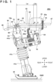
- FIG. 1 is a view showing a configuration of a rammer 40A as an example of a configuration of the ground compacting device according to the first embodiment.
- the right side of the page surface is the front of the apparatus
- the left side of the page surface is the rear of the apparatus
- directions intersecting the front-rear directions are upper-lower directions of the apparatus.
- the rammer 40A includes a motor 10 as a drive source, an upper portion (hereinafter, also referred to as "upper half 41b ”) on the upper side of an anti-vibration member 41c described later, an expandable/contractable anti-vibration member 41c, a lower portion (hereinafter, also referred to as “lower half 41a ”) on the lower side of the anti-vibration member 41c, and a ground leveling plate 42.
- the ground leveling plate 42 is connected to the lower half 41a, and the lower half 41a is connected to the upper half 41b via the anti-vibration member 41c.
- the upper half 41b is provided with a handle 45 and a support portion 70 separate from the handle 45.
- a mounting plate 54 to which electrical components such as batteries and Power Drive Units (PDUs) can be mounted.
- a battery 51 for supplying electric power to the motor 10 is mounted on the upper surface of the mounting plate 54 via a holding tray 53.
- a PDU case 56 on which a PDU 55 for controlling the driving of the motor 10 is disposed is mounted on the lower surface of the mounting plate 54.
- a mounting structure of these electrical components will be described later in detail with reference to FIG. 3 .
- the motor 10 is attached to the upper half 41b via a spacer 15, and is driven based on electric power supplied from the battery 51.
- a vibration mechanism (not shown) accommodated in the upper half 41b is connected to an output shaft of the motor 10.
- a rotational drive of the output shaft of the motor 10 is converted into a reciprocating linear motion (vertical motion) by a piston rod (not shown), and the converted vertical motion is transmitted to the ground leveling plate 42.
- the ground leveling plate 42 vibrates in the vertical direction.
- the ground GND can be compacted by the vibration of the ground leveling plate 42.
- the anti-vibration member 41c is provided between the upper half 41b and the lower half 41a.
- a reaction moves the rammer 40A up and down, but the vibration of the ground leveling plate 42 and the lower half 41a side is transmitted to the upper half 41b side such that it is reduced by to the interposition of the anti-vibration member 41c.
- FIG. 3 is a diagram illustrating a mounting structure of the electrical components (the battery 51, the PDU 55).
- the mounting plate 54 is a plate attached to the support portion 70, and electrical components such as the battery 51 and the PDU can be attached to an upper surface 354A (first surface) and a lower surface 354B (second surface which is the back surface of the first surface) of the mounting plate 54.
- a holding tray 53 for mountably/demountably holding the battery 51 is attached to the upper surface 354A of the mounting plate 54 by a fastening member 53f (for example, a bolt).
- the battery 51 is mountably/demountably held by the holding tray 53, and is attached to the upper surface 354A of the mounting plate 54 via the holding tray 53.
- the motor connection portion 51a can be connected to a connector cable 55a which is electrically connected to the motor 10 via a PDU 55.
- the motor 10 and the PDU 55 are electrically connected via a cable 55b, and the connector cable 55a is connected to the motor connection portion 51a in a state in which the battery 51 is mounted on the holding tray 53, whereby the motor 10 and the battery 51 are electrically connected via the connector cable 55a, the PDU 55, and the cable 55b.
- An external member 52 (cosmetic member) has an opening 352 in its center.
- the external member 52 is attached to the upper surface 354A of the mounting plate 54 by a fastening member 52a (e.g., bolt), and in a state in which it is mounted on the mounting plate 54, the external member 52 covers the outer periphery of the holding tray 53 and the lower portion of the battery 51.
- a fastening member 52a e.g., bolt
- the PDU 55 is disposed in a protective PDU case 56, and the PDU case 56 with the PDU 55 disposed thereon is attached to the lower surface 354B of the mounting plate 54 by a fastening member 56a.
- the space of the lower surface side of the mounting plate 54 can be more effectively utilized as compared with a structure in which the electrical components are stacked on the surface on one side (for example, the upper surface side), and therefore the device configuration can be made smaller. Since the battery 51 needs to be charged by a charger outside the device at a predetermined time, the frequency of mounting/demounting of the battery 51 is higher than that of the PDU 55.
- FIG. 6 is a view for explaining a mounting/demounting structure of the battery 51.
- the right side of the page surface corresponds to the left side of the apparatus, and the left side of the page surface corresponds to the right side of the apparatus.
- ST61 is a view showing a state in which the battery 51 is placed on the holding tray 53. The operator can carry the battery 51 by gripping a battery gripping portion 156 provided on the upper portion of the battery 51, and can place the battery 51 on the holding tray 53 following the arrow 50A.
- An engagement convex portion 53c is formed at a right end portion of the holding tray 53, and the engagement convex portion 53c engages with an engagement concave portion 51e formed at the right end portion of the battery 51, thereby defining a holding position for the battery 51 on the holding tray 53.
- ST62 is a view showing a state in which the battery 51 has been placed on the holding tray 53.
- the battery 51 is placed on the holding tray 53 in a state in which the holding position is determined by the engagement between the engagement convex portion 53c and the engagement concave portion 51e, seats 51a and 51b provided on the lower surface of the battery 51 come into contact with elastic bodies (for example, rubbers 53a and 53b) provided on the holding tray 53, respectively.
- elastic bodies for example, rubbers 53a and 53b
- a holding wire 57 for holding the battery 51 placed on the holding tray 53 is provided at the right end portion (left side in the page surface) of the holding tray 53, and the left end portion (right side in the page surface) of the holding wire 57 is rotatably supported by a wire support portion 53d.
- a holding lever 58 is provided at a right end portion (the left side of the page surface) of the holding wire 57.
- the holding lever 58 is rotatable about a rotation fulcrum 58a, and when the holding lever 58 is rotated about the rotation fulcrum 58a as indicated by an arrow 50B, the holding convex portion 58b formed at the distal end portion of the holding lever 58 engages with a holding concave portion 51d formed at the upper portion of the battery 51 to be held.
- ST63 is a view showing a state in which the battery 51 has been held on the holding tray 53.
- the battery 51 is held on the holding tray 53 by the engagement of the engagement convex portion 53c and the engagement concave portion 51e on the right side (the left side of the apparatus) of the page surface, and is held on the holding tray 53 by the engagement of a holding convex portion 58b and a holding concave portion 5 1d on the left side (the right side of the apparatus) of the page surface.
- FIG. 2 is a view showing a configuration of the support portion. Electrical components (the battery 51 and the PDU 55 which is disposed in the PDU case 56) are attached to the support portion 70 via the mounting plate 54.
- the support portion 70 is formed as a substantially U-shaped frame body by the left and right frames 70a and 70b and a center frame 70c, and the mounting plate 54 is mounted between the left and right frames 70a and 70b by the fastening member 54a (for example, a bolt).
- Connecting portions 71a and 71b for connecting the support portion 70 to an anti-vibration member 73 are provided at the end portions of the left and right frames 70a and 70b.
- the connection portion 71b is formed with a through hole 71c that a rotating support member 77a (e.g., a bolt) passes through.
- ST21 shows a cross-sectional view of the anti-vibration member 73 along a rotational axis 80.
- the anti-vibration member 73 has an anti-vibration member main body 73a having a hollow cylindrical shape, an elastic member 72 inserted into the anti-vibration member main body 73a, and a collar 76 inserted into an opening 72a formed in a central portion of the elastic member 72.
- An inner diameter 76a of the collar 76 is formed so as to be able to pass through the rotating support member 77a.
- the rotating engagement member 77b for example, a nut
- FIG. 2 a configuration example is shown in which the anti-vibration member 73 is attached to the connection portion 71b of the right frame 70b, but the same is true for a left frame 70a, and the anti-vibration member 73 is attached to the connection portion 71a of the left frame 70a by engaging the rotating engagement member 77b with the rotating support member 77a passing through the through hole 71c formed in the connection portion 71a of the left frame 70a and the collar 76 of the anti-vibration member 73.
- An upper anti-vibration mounting member 74 has a semi-cylindrical arc portion 74a and flange portion 74b formed at both ends of the arc portion 74a.
- a through hole 78c is formed in the flange portion 74b such that a fastening member 78a (e.g., a bolt) can pass through.
- a lower anti-vibration mounting member 75 has a semi-cylindrical arc portion 75a, a first flange portion 75b formed at both ends of the arc portion 75a, a step portion 75d formed in the vertical direction from the end of the first flange portion 75b, and a second flange portion 75c formed at the end of the step portion 75d.
- the first flange portion 75b is formed with an engagement portion 78b (e.g., a screw hole) that engages with the fastening member 78a.
- a through hole 79b is formed in the second flange portion 75c such that a fastening member 79a (e.g., a bolt) can pass through.
- the upper anti-vibration mounting member 74 and the lower anti-vibration mounting member 75 are mounted on the support portion 70 by engaging the fastening member 78a with the engagement portion 78b in a state in which the anti-vibration member 73 is sandwiched therebetween vertically.
- the arc portion 74a and the arc portion 75a sandwich the outer circumference of the anti-vibration member main body 73a vertically, rotatably hold the support portion 70, and hold the position of the support portion 70 in the rotated state.
- FIG. 2 shows an example in which the second flange portion 75c is brought into contact with a handle holding member 44, which holds the handle 45, and fastened by the fastening member 79a, but the present invention is not limited to this, and the frame may be extended upward from the spacer 15, and the support portion 70 may be provided on the frame via the anti-vibration member 73.
- an engagement portion e.g., a screw hole
- the shape of the second flange portion 75c is not limited to a planar shape, and can be formed according to a shape of a component (the handle holding member 44) on the side of the upper half 41b that comes into contact with it.
- the handle holding member 44 is a component having a cylindrical outer shape
- the second flange portion 75c may be formed as an arc shape having a curvature matched with the cylindrical outer shape.
- the handle holding member 44 is a component having a planar outer shape
- the second flange portion 75c may be formed to be flat.
- the handle 45 is rotatably attached to the upper half 41b by the handle holding member 44 having the same structure as the anti-vibration member 73, and is configured to be rotatable in the vertical direction about a rotational axis 90 of the handle holding member 44 as a rotation center ( FIG. 1 ).
- the support portion 70 is attached to the handle holding member 44 by engagement between the fastening member 79a passing through the through hole 79b of the second flange portion 75c ( FIG. 2 ) and the handle holding member 44, and is configured to be rotatable in the vertical direction where the rotational axis 80 of the anti-vibration member 73 is the center of rotation.
- Vibration transmitted from the ground leveling plate 42 acts on the anti-vibration member 73 as an exciting force F at the center of the anti-vibration member 73, i.e., the rotational axis 80.
- the support portion 70 has a cantilever structure supported by the anti-vibration member 73, and the support portion 70 of the cantilever structure is excited by the exciting force F.
- the center of gravity G indicates the overall center of gravity of the support portion 70 and the electrical components (battery 51, PDU 55), the external member 52, the holding tray 53, the mounting plate 54, and the PDU case 56 (hereinafter, these overall configurations are also referred to as "support units").
- La represents the distance (length) from the center (the rotational axis 80) of the anti-vibration member 73 to the center of gravity G of the support unit.
- a point C indicates a position at which the electrical components (the battery 51 and the PDU 55) are attached to the mounting plate 54 (the center position of the electrical components in the front-rear directions)
- Lb indicates a distance (length) from the center of gravity G to the position C.
- the elastic modulus (spring constant) of the elastic member 72 of the anti-vibration member 73 is set to be sufficiently smaller than the vibration frequency of the rammer 40A, the influence of resonance can be reduced.
- An elastic member is also provided inside the handle holding member 44 as in the anti-vibration member 73 (ST21 of FIG. 2 ).
- the elastic members of the anti-vibration member 73 of the support portion 70 and the handle holding member 44 of the handle 45 it is possible to use members having a different elastic modulus in accordance with the vibration characteristics of the support portion 70 and the vibration characteristics of the handle 45.
- the anti-vibration member 73 of the support portion 70 is provided separately from the anti-vibration member of the handle 45 (the handle holding member 44 including the anti-vibration member), and interposed between the upper half 41b and the support portion 70. This makes it possible to individually suppress the vibration of the handle 45 and the electrical components attached to the support portion 70. According to the apparatus configuration of the present embodiment, it is possible to reduce vibration of the electrical components separately from the handle.
- the support portion 70 is provided lower than the handle 45, and the handle 45 is configured to cover at least a part of the electrical components (e.g., the battery 51 and the PDU 55 disposed in the PDU case 56) attached to the support portion 70.
- the electrical components e.g., the battery 51 and the PDU 55 disposed in the PDU case 56
- a reinforcing member 63 is attached between the right handle frame 48 and the left handle frame 49 constituting the handle 45, and the reinforcing member 63 protects the battery 51.
- the reinforcing member 64 connects the handle 45 to a movable plate 43 of the upper half 41b, and covers at least a part of the electrical components (e.g., the battery 51 and the PDU 55 disposed in the PDU case 56) attached to the support portion 70 and at least a part of the motor 10.
- the electrical components and the motor 10 can be protected by the reinforcing member 64 when the apparatus falls over or the like.
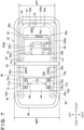
- FIG. 4 is a view of the rammer 40A as seen from above.
- the handle 45 has a front frame 47, a rear frame 46, the right handle frame 48, and the left handle frame 49, and is formed as a substantially rectangular frame body.
- the support portion 70 is formed as a substantially U-shaped frame body by the left and right frames 70a and 70b and the center frame 70c, and the support portion 70 is disposed inside the frame body of the handle 45.
- the worker When a worker engages in a ground leveling operation, the worker must hold the front frame 47 (handle portion) on the handle 45 of the rammer 40A, and perform an operation of rotating the handle 45 upwardly and downwardly, and pushing downwards; however, by providing the support portion 70 inside the frame body of the handle 45, the device configuration can be made compact and interference with the support portion 70 when the handle 45 is rotated can be prevented.
- the handle holding member 44 is provided separately from the anti-vibration member 73 and the electrical components are provided in the support portion 70 (the electrical components are not provided in the handle 45), the electrical components do not rotate in conjunction with the rotation of the handle, and so it is possible to suppress interference of the electrical components with other components (motors and the like) of the apparatus.
- the anti-vibration member 73 is disposed in the handle holding member 44 by arranging the rotational axis 80 of the anti-vibration member 73 in the support portion 70 coaxially with the rotational axis 90 of the handle holding member 44.
- the support portion 70 is disposed lower than the handle 45 as the apparatus configuration, but in addition to this example, it is also possible to adopt an apparatus configuration in which the support portion 70 is disposed higher than the handle 45 as the apparatus configuration.
- the vertical height of the step portion 75d of the lower anti-vibration mounting member 75 illustrated in FIG. 2 may be formed to be a length such that the support portion 70 is disposed higher than the handle 45, or the upper end portion (the upper half 41b) of the device may be formed so as to project higher than the handle 45, and the support portion 70 may be provided through the anti-vibration member 73 in the protruding portion.
- a weight-adjusting portion may be provided on the support portion 70 on a side opposite to a position where the electrical components (the battery 51 and the PDU 55) are mounted via the anti-vibration member 73 of the support portion 70.
- the electrical components the battery 51 and the PDU 55
- extension frames 70d and 70e in which the left and right frames 70a and 70b constituting the support portion 70 are extended to the rear side of the apparatus, and to provide counterweights W in the extension frames 70d and 70e as weight-adjusting portions.
- the counterweights W can be adjusted by increasing or decreasing the weight, and the moment about the center of gravity G of the electrical components (clockwise direction) can be reduced by the moment about the center of gravity G of the weight-adjusting portion (the counterweights W) (counterclockwise direction).
- the moment about the center of gravity G of the electrical components By reducing the moment about the center of gravity G of the electrical components, the position C at which the electrical components are attached can be moved towards the center of gravity G, and the protrusion length L1 ( FIG. 1 ) of the support portion 70 which protrudes forward from the electrical component can be shortened.
- the protrusion length L1 of the support portion 70 By shortening the protrusion length L1 of the support portion 70, the clearance L2 between the center frame 70c of the support portion 70 and the front frame 47 of the handle 45 can be enlarged. As a result, it is possible to prevent interference with the support portion 70 during rotation of the handle 45 while making the device configuration more compact.
- FIG. 2 a configuration example of a plurality of frames (the left and right frames 70a and 70b and the center frame 70c) is shown as the support portion 70, but the support portion 70 may be configured by a plate-shaped member (a plate) in addition to this example.
- a plate-shaped member a plate
- an opening for avoiding interference with the PDU case 56 attached to the lower surface 354B of the mounting plate 54 may be formed in the plate-shaped member.
- FIG. 7 is a view showing Variation 1 of the mounting plate 54, and is a view of the rammer 40A ( FIG. 1 ) as seen from above.
- the mounting structure of the electrical components (the battery 51 and the PDU 55) to the mounting plate 54 is the same as that shown in FIGS. 3 and 4
- the structure for connecting the end portions of the left and right frames 70a and 70b of the support portion 70 to the anti-vibration member 73 is the same as that shown in FIG. 2 .
- the structure of the weight-adjusting portion (counterweight W) of the support portion 70 is similar to that shown in FIG. 4 .
- the mounting plate 54 has a rectangular shape in a plan view, and is mounted by the fastening member 54a (for example, a bolt) so as to cover the upper surface of the support portion 70.
- the support portion 70 is formed as a substantially U-shaped frame body by the left and right frames 70a and 70b and the center frame 70c, and the portion of the structure of the support portion 70 shown by broken lines is provided on the lower surface of the mounting plate 54.
- a left end portion 254a of the mounting plate 54 protrudes from the left frame 70a of the support portion 70 to the outside of the frame body (an overhang length Ls).
- a right end portion 254b of the mounting plate 54 protrudes from the right frame 70b of the support portion 70 to the outside of the frame body (the overhang length Ls).
- a front end portion 254c of the mounting plate 54 protrudes from the center frame 70c to the outside of the frame body (the overhang length Ls).
- the mounting plate 54 is attached to the left frame 70a by the fastening member 54a at two locations, and is attached to the right frame 70b by the fastening member 54a at two locations.
- the mounting plate 54 is attached to the left frame 70a by the fastening member 54a at three locations, and is attached to the right frame 70b by the fastening member 54a at three locations, and furthermore is attached to the center frame 70c by the fastening member 54a at two locations.
- the mounting plate 54 can be disposed stably on the upper surface of the support portion 70, and the outer edge of the mounting plate 54 can be more firmly attached to the support portion 70.
- FIG. 8 is a view showing Variation 2 of the mounting plate 54, and is a view of the rammer 40A ( FIG. 1 ) as seen from above.
- the mounting plate 54 has a rectangular shape in a plan view, and similarly to Variation 1 in FIG. 7 , its structure is mounted by the fastening member 54a (for example, a bolt) so as to cover the upper surface of the support portion 70.
- the fastening member 54a for example, a bolt
- a portion indicated by broken lines is provided on the lower surface of the mounting plate 54.
- the structure of the weight-adjusting portion (counterweight W) of the support portion 70 is similar to that shown in FIG. 4 and FIG. 7 .
- the length LP2 of the mounting plate 54 in the left/right direction in FIG. 8 is configured to be shorter than the length LP1 of the mounting plate 54 the left/right direction in FIG. 7 (LP2 ⁇ LP1).
- the structure that connects the ends of the left and right frames 70a and 70b of the support portion 70 to the anti-vibration member 73 is the same as in FIG. 2 , but the orientation for mounting the electrical components (the battery 51) to the mounting plate 54 is different from that in FIGS. 4 and 7 in Variation 2 of FIG. 8 .
- the longitudinal direction of the battery 51 is disposed along the left/right direction of the rammer 40A, but in Variation 2 of FIG. 8 , the longitudinal direction of the battery 51 is disposed along the front-rear direction of the rammer 40A.
- the mounting plate 54 can be disposed stably on the upper surface of the support portion 70, and the outer edge of the mounting plate 54 can be more firmly attached to the support portion 70.
- the device width (WD2) of the rammer 40A of Variation 2 can be reduced (WD2 ⁇ WD1) as compared with the device width (WD1) of the rammer 40A of Variation 1, and a more compact rammer 40A can be provided.
- FIG. 9 is a view showing Variation 3 of the mounting plate 54, and is a view of the rammer 40A ( FIG. 1 ) as seen from above.
- the mounting plate 54 has a rectangular shape in a plan view, and is mounted by the fastening member 54a (for example, a bolt) so as to cover the upper surface of the support portion 70.
- the fastening member 54a for example, a bolt
- a portion indicated by broken lines is provided on the lower surface of the mounting plate 54.
- the structure of the support portion 70 is different from the structure of Variations 1 and 2 of the first embodiment of FIG. 4 , FIG. 7 and FIG. 8 .
- the support portion 70 is formed as a substantially U-shaped frame body by the left and right frames 70a and 70b, and the center frame 70c, but in Variation 3 of FIG. 9 , there is a difference in that the support portion 70 is formed in a substantially T-like shape by a front/rear direction frame 170a and a left/right direction frame 170b.
- a member width WD4 of the front/rear direction frame 170a and the left/right direction frame 170b is formed wider than a member width WD3 of the frames (the left frame 70a, the right frame 70b, and the center frame 70c) shown in FIG. 7 and FIG. 8 , for example, so that the stiffness of the support portion 70 is not lowered as compared with Variations 1 and 2 of the first embodiment of FIG. 4 , FIG. 7 , and FIG. 8 (WD4>WD3).
- the member width WD4 is formed wider than the member width WD3, but the present invention is not limited to this example, and the member thicknesses of the front/rear direction frame 170a and the left/right direction frame 170b may be formed thicker than the member thicknesses of the frames (the left frame 70a, the right frame 70b, and the center frame 70c) shown in FIG. 7 and FIG. 8 , for example, in the direction perpendicular to the page surface.
- a stiffness equivalent to that of the support portion 70 shown in FIG. 4 , FIG. 7 and FIG. 8 can be realized.
- the structure is such that the ends of the left and right frames 70a and 70b of the support portion 70 are connected to the left and right anti-vibration members 73, respectively ( FIG. 2 ), but in Variation 3 of FIG. 9 , the structure is such that the end of the front/rear direction frame 170a is connected to a single anti-vibration member 73.
- Variation 3 of the mounting plate 54 shown in FIG. 9 it is possible to reduce the number of components (for example, the elastic member 72, the upper anti-vibration mounting member 74, the lower anti-vibration mounting member 75, the collar 76, and the like shown in FIG. 2 ) for connection to the anti-vibration member 73, and it is possible to simplify the structure of the anti-vibration member 73.
- the Variations 1 and 2 of FIG. 7 and FIG. 8 are used as the weight-adjusting portions.
- Variation 3 of FIG. 9 by providing two counterweights 2W as one counterweight, the same weight adjustment effect as that of the first embodiment of FIG. 4 and the Variations 1 and 2 of FIG. 7 and FIG. 8 can be realized.
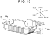
- the structure is such that the PDU case 56 is mounted to the lower surface 354B ( FIG. 3 ) of the mounting plate 54, but in the Variation 3 of FIG. 9 , the PDU case 56 can be attached to the lower surface 354B ( FIG. 3 ) of the mounting plate 54 by forming the notches 56b and 56c ( FIG. 10 ) in the PDU case 56 that can intersect with the front/rear direction frame 170a while avoiding interference with the front/rear direction frame 170a.
- the space on the lower surface side of the mounting plate 54 can be effectively utilized in Variation 3 as in Variations 1 and 2 of the first embodiment of FIG. 4 , FIG. 7 , and FIG. 8 , and so the device configuration can be reduced in size.
- Variation 3 of FIG. 9 an example is shown in which the longitudinal direction of the battery 51 is disposed in the left/right direction of the rammer 40A as in the first embodiment of FIG. 4 and Variation 1 of FIG. 7 .
- the arrangement direction of the battery 51 is not limited to this example, and for example, as in Variation 2 of FIG. 8 , the rammer 40A may be configured such that the longitudinal direction of the battery 51 is disposed in the front-rear direction of the rammer 40A. This makes it possible to reduce the device width of the rammer 40A of Variation 3 as in Variation 2, and to provide a more compact rammer 40A.
- FIG. 5 is a view showing a configuration of a plate compactor 40B as an example not being part of the present invention.
- the plate compactor 40B includes a motor 150 functioning as a drive source, upper halves 144 and 154 upward of an anti-vibration member 146, the anti-vibration member 146, a lower half 145 downward of the anti-vibration member 146, an excitation mechanism 158, and a ground leveling plate 142.
- a handle 147 is configured as a substantially rectangular frame body like the handle 45 described in the first embodiment. The handle 147 is attached to the upper half 144.
- the ground leveling plate 142 is connected to the lower half 145, and the lower half 145 and the ground leveling plate 142 vibrate by vibration of the excitation mechanism 158.
- the motor 150 is provided in an upper half 154 via a spacer 151, and a drive pulley 152 is attached to an output shaft 150a of the motor 150.
- a driven pulley 153 is attached to a rotational axis 153a of the excitation mechanism 158, and a power transmission mechanism 155 (drive belt) is provided between the drive pulley 152 and the driven pulley 153.
- the rotational driving force of the motor 150 is transmitted to the excitation mechanism 158 via the drive pulley 152, the power transmission mechanism 155, and the driven pulley 153, and the lower half 145 and the ground leveling plate 142 vibrate by vibration of the excitation mechanism 158 based on the transmitted rotational driving force.
- the reaction to the vibration of the ground leveling plate 142 causes a plate compactor 40B to move up and down, but the vibration of the ground leveling plate 142 and the lower half 145 side, after being reduced by the interposition of the anti-vibration member 146, is transmitted to the upper halves 144 and 154 and the side of the handle 147 attached to the upper half 144.
- the anti-vibration member 146 functions as an anti-vibration member for the upper halves 144 and 154 and the handle 147 attached to the upper half 144, and has a configuration separate from the anti-vibration member 73 of the support portion 70, which will be described later.
- the support portion 70 is attached to the upper half 154 via the anti-vibration member 73 separately from the anti-vibration member 146 of the handle 147, and electrical components for driving the motor 150 are attached to the support portion 70.
- the structures of the upper anti-vibration mounting member 74, the lower anti-vibration mounting member 75, and the elastic member 72 for mounting the anti-vibration member 73 to the upper half 154 are similar to those of the first embodiment.
- a structure for a weight-adjusting portion a structure in which an extension frame 70e in which the support portion 70 is extended to the rear side of the apparatus is formed, and as the weight-adjusting portion, the counterweight W is provided in the extension frame 70e, is also similar to in the first embodiment.
- the structure for attaching the electrical components to the support portion 70 is also the similar to the structure described with reference to FIG. 2 and FIG. 3 .
- an electrical component the battery 51 included in the electrical component
- another electrical component another electrical component (for example, the PDU 55) included in the electrical component)
- the space of the lower surface side of the mounting plate 54 can be more effectively utilized as compared with a structure in which the electrical components are stacked on the surface on one side, and therefore the device configuration can be made smaller.
- the relative positional relationship between the handle 147 and the support portion 70 described in the first embodiment can be applied to the handle 147 and the support portion 70 of the example not being part of the present invention.
- a plate compactor capable of reducing vibration of an electrical component separately from a handle.
- Variations 1 to 3 of the mounting plate 54 described with reference to FIG. 7 to FIG. 10 can also be applied to the mounting plate 54 ( FIG. 5 ) of the example not being part of the present invention.
Landscapes
- Engineering & Computer Science (AREA)
- Structural Engineering (AREA)
- Civil Engineering (AREA)
- Life Sciences & Earth Sciences (AREA)
- Environmental & Geological Engineering (AREA)
- Soil Sciences (AREA)
- General Life Sciences & Earth Sciences (AREA)
- Mining & Mineral Resources (AREA)
- Paleontology (AREA)
- Agronomy & Crop Science (AREA)
- General Engineering & Computer Science (AREA)
- Architecture (AREA)
- Road Paving Machines (AREA)
- Investigation Of Foundation Soil And Reinforcement Of Foundation Soil By Compacting Or Drainage (AREA)
Claims (7)
- Dispositif de compactage du sol (40A) comportant une plaque de nivelage du sol (42) et un moteur (10) pour entraîner la plaque de nivelage du sol (42), le dispositif de compactage du sol (40A) comprend :une partie support (70) qui est fixée à une moitié supérieure (41b) du dispositif de compactage du sol (40A) par l'intermédiaire d'un élément antivibratoire (73) séparément d'une poignée (45),dans lequel un composant électrique pour entraîner le moteur (10) est fixé à la partie support ; caractérisé en ce quel'élément antivibratoire (73) est disposé dans un élément de maintien de poignée (44) qui maintient la poignée (45), par l'agencement d'un axe de rotation (80) de l'élément antivibratoire (73) dans la partie support (70) de manière coaxiale à un axe de rotation (90) de l'élément de maintien de poignée (44).
- Dispositif de compactage du sol (40A) selon la revendication 1, dans lequel la poignée (45) est configurée comme un corps de carde sur une vue de surface supérieure du dispositif de compactage du sol (40A), et
la partie support (70) est disposée à l'intérieur du corps de cadre de la poignée (45). - Dispositif de compactage du sol (40A) selon la revendication 1 ou 2, comprenant en outre une partie de réglage du poids (70e, W) sur un côté opposé à une position où est fixé le composant électrique, par l'intermédiaire de l'élément antivibratoire (73) de la partie support (70).
- Dispositif de compactage du sol (40A) selon l'une quelconque des revendications 1 à 3, dans lequel la partie support (70) est disposée plus bas que la poignée (45) sur une vue latérale du dispositif de compactage du sol (40A) et la poignée (45) recouvre au moins une partie du composant électrique.
- Dispositif de compactage du sol (40A) selon l'une quelconque des revendications 1 à 4, dans lequel la partie support (70) comporte au moins une plaque (54), etune batterie (51) comprise dans le composant électrique est fixée à une surface supérieure (354A) de la plaque (54), etun autre composant électrique compris dans le composant électrique est fixé à une surface inférieure (354B) de la plaque (54), qui est une surface arrière de la surface supérieure.
- Dispositif de compactage du sol (40A) selon l'une quelconque des revendications 1 à 5, comprenant en outre un élément de renforcement (64) reliant la poignée (45) et la moitié supérieure (41b),
dans lequel l'élément de renforcement (64) recouvre au moins une partie du composant électrique fixé à la partie support (70). - Dispositif de compactage du sol (40A) selon la revendication 6, dans lequel l'élément de renforcement (64) recouvre au moins une partie du moteur (10).
Applications Claiming Priority (2)
| Application Number | Priority Date | Filing Date | Title |
|---|---|---|---|
| PCT/JP2019/015211 WO2020202573A1 (fr) | 2019-04-05 | 2019-04-05 | Dispositif de compactage |
| PCT/JP2019/018906 WO2020202585A1 (fr) | 2019-04-05 | 2019-05-13 | Dispositif de consolidation de sol |
Publications (3)
| Publication Number | Publication Date |
|---|---|
| EP3744897A4 EP3744897A4 (fr) | 2020-12-02 |
| EP3744897A1 EP3744897A1 (fr) | 2020-12-02 |
| EP3744897B1 true EP3744897B1 (fr) | 2023-09-13 |
Family
ID=72666714
Family Applications (1)
| Application Number | Title | Priority Date | Filing Date |
|---|---|---|---|
| EP19726301.5A Active EP3744897B1 (fr) | 2019-04-05 | 2019-05-13 | Dispositif de consolidation de sol |
Country Status (5)
| Country | Link |
|---|---|
| US (1) | US20220018073A1 (fr) |
| EP (1) | EP3744897B1 (fr) |
| JP (1) | JP6595747B1 (fr) |
| CN (1) | CN113646483A (fr) |
| WO (2) | WO2020202573A1 (fr) |
Families Citing this family (8)
| Publication number | Priority date | Publication date | Assignee | Title |
|---|---|---|---|---|
| US11677293B2 (en) | 2021-01-27 | 2023-06-13 | Honda Motor Co., Ltd. | Electric motor conversion system |
| GB2604347A (en) * | 2021-03-01 | 2022-09-07 | Black & Decker Inc | A compacting power tool |
| GB2604349A (en) * | 2021-03-01 | 2022-09-07 | Black & Decker Inc | A compacting power tool |
| SE544979C2 (en) * | 2021-06-14 | 2023-02-14 | Husqvarna Ab | An electric compactor with battery system redundancy |
| WO2023009800A1 (fr) | 2021-07-30 | 2023-02-02 | Milwaukee Electric Tool Corporation | Compacteur à plaque |
| US20230049127A1 (en) * | 2021-08-11 | 2023-02-16 | Milwaukee Electric Tool Corporation | Rammer with vibration isolation |
| JP7499517B2 (ja) * | 2021-11-18 | 2024-06-14 | 伊岳商事株式会社 | ハンドタイタンパー |
| US12584283B2 (en) * | 2023-01-26 | 2026-03-24 | Dr. Strong Technology Development Ltd. | Ground compacting machine with a vibration damping assembly |
Family Cites Families (17)
| Publication number | Priority date | Publication date | Assignee | Title |
|---|---|---|---|---|
| JPS5976604U (ja) * | 1982-11-12 | 1984-05-24 | 北海道軌道施設工業株式会社 | 2面型電動式道床用締固め機 |
| JP3032466B2 (ja) * | 1996-03-29 | 2000-04-17 | エクセン株式会社 | コンパクタ |
| EP1196309B1 (fr) * | 1999-07-27 | 2004-01-14 | Wacker Construction Equipment AG | Dispositif de compactage du sol pourvu d'une fixation pour batterie de demarrage qui isole des vibrations |
| JP4532021B2 (ja) | 2001-06-04 | 2010-08-25 | 本田技研工業株式会社 | ランマ用エンジン |
| US20060291958A1 (en) * | 2005-06-28 | 2006-12-28 | Pirandello Industries Ltd. | Leveling blade, vibrating screed including the blade, and kit for assembling the same |
| DE102010046401A1 (de) * | 2010-09-23 | 2012-01-19 | Bomag Gmbh | Arbeitsgerät zur Verdichtung eines Untergrundes |
| DE102010055632A1 (de) * | 2010-12-22 | 2012-06-28 | Wacker Neuson Produktion GmbH & Co. KG | Bodenverdichtungsvorrichtung mit luftgekühlten Akku |
| DE102011100154A1 (de) * | 2011-05-02 | 2012-11-08 | Bomag Gmbh | Verbindungskonsole und Stampfgerät mit einer solchen Verbindungskonsole sowie Verfahren zu deren Herstellung |
| DE102011105899A1 (de) * | 2011-06-28 | 2013-01-03 | Bomag Gmbh | Vorrichtung zur Bodenverdichtung, insbesondere handgeführt, mit elektrischem Antrieb und Verfahren zum Betrieb einer solchen Vorrichtung |
| DE102011115008A1 (de) * | 2011-10-06 | 2013-04-11 | Wacker Neuson Produktion GmbH & Co. KG | Elektrowerkzeug mit Schutzhaube |
| DE102012024222A1 (de) * | 2012-12-11 | 2014-06-12 | Bomag Gmbh | Vibrationsstampfer |
| JP6063305B2 (ja) * | 2013-03-07 | 2017-01-18 | 富士重工業株式会社 | タンピングランマー、およびタンピングランマー用エンジンユニット |
| DE102014011179A1 (de) * | 2014-07-31 | 2016-02-04 | Wacker Neuson Produktion GmbH & Co. KG | Bodenverdichtungsvorrichtung mit Abfederung und Führung |
| JP2016216939A (ja) * | 2015-05-15 | 2016-12-22 | 株式会社日立建機カミーノ | プレートコンパクタの防振装置 |
| JP6499141B2 (ja) * | 2016-10-31 | 2019-04-10 | 三笠産業株式会社 | バイブロコンパクタ |
| DE102017121177A1 (de) * | 2017-09-13 | 2019-03-28 | Wacker Neuson Produktion GmbH & Co. KG | Bodenverdichtungsvorrichtung |
| CN208517793U (zh) * | 2018-07-03 | 2019-02-19 | 张振东 | 一种高速公路用振动式修补压实装置 |
-
2019
- 2019-04-05 WO PCT/JP2019/015211 patent/WO2020202573A1/fr not_active Ceased
- 2019-05-13 EP EP19726301.5A patent/EP3744897B1/fr active Active
- 2019-05-13 WO PCT/JP2019/018906 patent/WO2020202585A1/fr not_active Ceased
- 2019-05-13 JP JP2019543128A patent/JP6595747B1/ja active Active
- 2019-05-13 CN CN201980094885.7A patent/CN113646483A/zh active Pending
-
2021
- 2021-09-28 US US17/488,202 patent/US20220018073A1/en not_active Abandoned
Also Published As
| Publication number | Publication date |
|---|---|
| EP3744897A4 (fr) | 2020-12-02 |
| US20220018073A1 (en) | 2022-01-20 |
| CN113646483A (zh) | 2021-11-12 |
| EP3744897A1 (fr) | 2020-12-02 |
| JP6595747B1 (ja) | 2019-10-23 |
| WO2020202585A1 (fr) | 2020-10-08 |
| WO2020202573A1 (fr) | 2020-10-08 |
| JPWO2020202585A1 (ja) | 2021-04-30 |
Similar Documents
| Publication | Publication Date | Title |
|---|---|---|
| EP3744897B1 (fr) | Dispositif de consolidation de sol | |
| EP2721217B1 (fr) | Dispositif de compactage de sol | |
| JP5580528B2 (ja) | 手持ち式工具装置 | |
| EP3381619B1 (fr) | Machine de travail à mouvement alternatif | |
| US10208825B2 (en) | Anti-vibration device for vehicle | |
| US11306446B2 (en) | Hand-held work tool with decoupled drawbar carrier | |
| WO2008069282A1 (fr) | Dispositif d'amortissement de vibration, procédé de commande de dispositif d'amortissement de vibration, procédé de correction de décalage de dispositif d'amortissement de vibration et ressort à lames | |
| CN102900804B (zh) | 车辆用隔振装置 | |
| JPS5824235B2 (ja) | 携帯用工具における防振装置 | |
| CN114630578A (zh) | 作业机 | |
| JP2022538912A (ja) | 手持ち式電動工具 | |
| US20200262287A1 (en) | Engine mount pendulum support device | |
| US6582155B1 (en) | Soil packing device with a vibration isolating mounting for a starter battery | |
| CN111788351A (zh) | 压实机 | |
| US12486622B2 (en) | Hand-held tamping machine for compacting track ballast | |
| JP3851084B2 (ja) | 上部質量体の振動が低減された作業装置 | |
| CN113710410A (zh) | 熔渣除去装置、熔渣除去方法、焊接机器人以及防振装置 | |
| JP4650836B2 (ja) | 手持ち式動力作業機のハンドル支持構造 | |
| JP7681409B2 (ja) | 打撃工具 | |
| CN115822297A (zh) | 输电铁塔的套筒式加固装置 | |
| JP6493200B2 (ja) | 車両搭載用の電池パック | |
| CN113640604A (zh) | 一种电动舵机综合试验装置 | |
| JP2021070129A (ja) | 電動工具 | |
| JP2013217400A (ja) | 車両用防振装置 | |
| EP3966451B1 (fr) | Conversion d'énergie vibratoire en énergie électrique dans une machine de compactage vibratoire |
Legal Events
| Date | Code | Title | Description |
|---|---|---|---|
| STAA | Information on the status of an ep patent application or granted ep patent |
Free format text: STATUS: UNKNOWN |
|
| STAA | Information on the status of an ep patent application or granted ep patent |
Free format text: STATUS: THE INTERNATIONAL PUBLICATION HAS BEEN MADE |
|
| PUAI | Public reference made under article 153(3) epc to a published international application that has entered the european phase |
Free format text: ORIGINAL CODE: 0009012 |
|
| STAA | Information on the status of an ep patent application or granted ep patent |
Free format text: STATUS: REQUEST FOR EXAMINATION WAS MADE |
|
| 17P | Request for examination filed |
Effective date: 20190604 |
|
| A4 | Supplementary search report drawn up and despatched |
Effective date: 20200130 |
|
| AK | Designated contracting states |
Kind code of ref document: A1 Designated state(s): AL AT BE BG CH CY CZ DE DK EE ES FI FR GB GR HR HU IE IS IT LI LT LU LV MC MK MT NL NO PL PT RO RS SE SI SK SM TR |
|
| AX | Request for extension of the european patent |
Extension state: BA ME |
|
| STAA | Information on the status of an ep patent application or granted ep patent |
Free format text: STATUS: EXAMINATION IS IN PROGRESS |
|
| 17Q | First examination report despatched |
Effective date: 20220121 |
|
| DAV | Request for validation of the european patent (deleted) | ||
| DAX | Request for extension of the european patent (deleted) | ||
| GRAP | Despatch of communication of intention to grant a patent |
Free format text: ORIGINAL CODE: EPIDOSNIGR1 |
|
| STAA | Information on the status of an ep patent application or granted ep patent |
Free format text: STATUS: GRANT OF PATENT IS INTENDED |
|
| INTG | Intention to grant announced |
Effective date: 20230419 |
|
| GRAS | Grant fee paid |
Free format text: ORIGINAL CODE: EPIDOSNIGR3 |
|
| GRAA | (expected) grant |
Free format text: ORIGINAL CODE: 0009210 |
|
| STAA | Information on the status of an ep patent application or granted ep patent |
Free format text: STATUS: THE PATENT HAS BEEN GRANTED |
|
| AK | Designated contracting states |
Kind code of ref document: B1 Designated state(s): AL AT BE BG CH CY CZ DE DK EE ES FI FR GB GR HR HU IE IS IT LI LT LU LV MC MK MT NL NO PL PT RO RS SE SI SK SM TR |
|
| RIN1 | Information on inventor provided before grant (corrected) |
Inventor name: ISHIZUKA, KUNIHIKO Inventor name: MIZUGUCHI, HIROSHI |
|
| REG | Reference to a national code |
Ref country code: CH Ref legal event code: EP |
|
| REG | Reference to a national code |
Ref country code: DE Ref legal event code: R096 Ref document number: 602019037336 Country of ref document: DE |
|
| REG | Reference to a national code |
Ref country code: IE Ref legal event code: FG4D |
|
| REG | Reference to a national code |
Ref country code: LT Ref legal event code: MG9D |
|
| REG | Reference to a national code |
Ref country code: NL Ref legal event code: MP Effective date: 20230913 |
|
| PG25 | Lapsed in a contracting state [announced via postgrant information from national office to epo] |
Ref country code: GR Free format text: LAPSE BECAUSE OF FAILURE TO SUBMIT A TRANSLATION OF THE DESCRIPTION OR TO PAY THE FEE WITHIN THE PRESCRIBED TIME-LIMIT Effective date: 20231214 |
|
| PG25 | Lapsed in a contracting state [announced via postgrant information from national office to epo] |
Ref country code: SE Free format text: LAPSE BECAUSE OF FAILURE TO SUBMIT A TRANSLATION OF THE DESCRIPTION OR TO PAY THE FEE WITHIN THE PRESCRIBED TIME-LIMIT Effective date: 20230913 Ref country code: RS Free format text: LAPSE BECAUSE OF FAILURE TO SUBMIT A TRANSLATION OF THE DESCRIPTION OR TO PAY THE FEE WITHIN THE PRESCRIBED TIME-LIMIT Effective date: 20230913 Ref country code: NO Free format text: LAPSE BECAUSE OF FAILURE TO SUBMIT A TRANSLATION OF THE DESCRIPTION OR TO PAY THE FEE WITHIN THE PRESCRIBED TIME-LIMIT Effective date: 20231213 Ref country code: LV Free format text: LAPSE BECAUSE OF FAILURE TO SUBMIT A TRANSLATION OF THE DESCRIPTION OR TO PAY THE FEE WITHIN THE PRESCRIBED TIME-LIMIT Effective date: 20230913 Ref country code: LT Free format text: LAPSE BECAUSE OF FAILURE TO SUBMIT A TRANSLATION OF THE DESCRIPTION OR TO PAY THE FEE WITHIN THE PRESCRIBED TIME-LIMIT Effective date: 20230913 Ref country code: HR Free format text: LAPSE BECAUSE OF FAILURE TO SUBMIT A TRANSLATION OF THE DESCRIPTION OR TO PAY THE FEE WITHIN THE PRESCRIBED TIME-LIMIT Effective date: 20230913 Ref country code: GR Free format text: LAPSE BECAUSE OF FAILURE TO SUBMIT A TRANSLATION OF THE DESCRIPTION OR TO PAY THE FEE WITHIN THE PRESCRIBED TIME-LIMIT Effective date: 20231214 Ref country code: FI Free format text: LAPSE BECAUSE OF FAILURE TO SUBMIT A TRANSLATION OF THE DESCRIPTION OR TO PAY THE FEE WITHIN THE PRESCRIBED TIME-LIMIT Effective date: 20230913 |
|
| REG | Reference to a national code |
Ref country code: AT Ref legal event code: MK05 Ref document number: 1611419 Country of ref document: AT Kind code of ref document: T Effective date: 20230913 |
|
| PG25 | Lapsed in a contracting state [announced via postgrant information from national office to epo] |
Ref country code: NL Free format text: LAPSE BECAUSE OF FAILURE TO SUBMIT A TRANSLATION OF THE DESCRIPTION OR TO PAY THE FEE WITHIN THE PRESCRIBED TIME-LIMIT Effective date: 20230913 |
|
| PG25 | Lapsed in a contracting state [announced via postgrant information from national office to epo] |
Ref country code: IS Free format text: LAPSE BECAUSE OF FAILURE TO SUBMIT A TRANSLATION OF THE DESCRIPTION OR TO PAY THE FEE WITHIN THE PRESCRIBED TIME-LIMIT Effective date: 20240113 |
|
| PG25 | Lapsed in a contracting state [announced via postgrant information from national office to epo] |
Ref country code: AT Free format text: LAPSE BECAUSE OF FAILURE TO SUBMIT A TRANSLATION OF THE DESCRIPTION OR TO PAY THE FEE WITHIN THE PRESCRIBED TIME-LIMIT Effective date: 20230913 |
|
| PG25 | Lapsed in a contracting state [announced via postgrant information from national office to epo] |
Ref country code: ES Free format text: LAPSE BECAUSE OF FAILURE TO SUBMIT A TRANSLATION OF THE DESCRIPTION OR TO PAY THE FEE WITHIN THE PRESCRIBED TIME-LIMIT Effective date: 20230913 |
|
| PG25 | Lapsed in a contracting state [announced via postgrant information from national office to epo] |
Ref country code: SM Free format text: LAPSE BECAUSE OF FAILURE TO SUBMIT A TRANSLATION OF THE DESCRIPTION OR TO PAY THE FEE WITHIN THE PRESCRIBED TIME-LIMIT Effective date: 20230913 Ref country code: RO Free format text: LAPSE BECAUSE OF FAILURE TO SUBMIT A TRANSLATION OF THE DESCRIPTION OR TO PAY THE FEE WITHIN THE PRESCRIBED TIME-LIMIT Effective date: 20230913 Ref country code: IS Free format text: LAPSE BECAUSE OF FAILURE TO SUBMIT A TRANSLATION OF THE DESCRIPTION OR TO PAY THE FEE WITHIN THE PRESCRIBED TIME-LIMIT Effective date: 20240113 Ref country code: ES Free format text: LAPSE BECAUSE OF FAILURE TO SUBMIT A TRANSLATION OF THE DESCRIPTION OR TO PAY THE FEE WITHIN THE PRESCRIBED TIME-LIMIT Effective date: 20230913 Ref country code: EE Free format text: LAPSE BECAUSE OF FAILURE TO SUBMIT A TRANSLATION OF THE DESCRIPTION OR TO PAY THE FEE WITHIN THE PRESCRIBED TIME-LIMIT Effective date: 20230913 Ref country code: CZ Free format text: LAPSE BECAUSE OF FAILURE TO SUBMIT A TRANSLATION OF THE DESCRIPTION OR TO PAY THE FEE WITHIN THE PRESCRIBED TIME-LIMIT Effective date: 20230913 Ref country code: AT Free format text: LAPSE BECAUSE OF FAILURE TO SUBMIT A TRANSLATION OF THE DESCRIPTION OR TO PAY THE FEE WITHIN THE PRESCRIBED TIME-LIMIT Effective date: 20230913 Ref country code: PT Free format text: LAPSE BECAUSE OF FAILURE TO SUBMIT A TRANSLATION OF THE DESCRIPTION OR TO PAY THE FEE WITHIN THE PRESCRIBED TIME-LIMIT Effective date: 20240115 Ref country code: SK Free format text: LAPSE BECAUSE OF FAILURE TO SUBMIT A TRANSLATION OF THE DESCRIPTION OR TO PAY THE FEE WITHIN THE PRESCRIBED TIME-LIMIT Effective date: 20230913 |
|
| PG25 | Lapsed in a contracting state [announced via postgrant information from national office to epo] |
Ref country code: PL Free format text: LAPSE BECAUSE OF FAILURE TO SUBMIT A TRANSLATION OF THE DESCRIPTION OR TO PAY THE FEE WITHIN THE PRESCRIBED TIME-LIMIT Effective date: 20230913 Ref country code: IT Free format text: LAPSE BECAUSE OF FAILURE TO SUBMIT A TRANSLATION OF THE DESCRIPTION OR TO PAY THE FEE WITHIN THE PRESCRIBED TIME-LIMIT Effective date: 20230913 |
|
| REG | Reference to a national code |
Ref country code: DE Ref legal event code: R097 Ref document number: 602019037336 Country of ref document: DE |
|
| PG25 | Lapsed in a contracting state [announced via postgrant information from national office to epo] |
Ref country code: DK Free format text: LAPSE BECAUSE OF FAILURE TO SUBMIT A TRANSLATION OF THE DESCRIPTION OR TO PAY THE FEE WITHIN THE PRESCRIBED TIME-LIMIT Effective date: 20230913 |
|
| PLBE | No opposition filed within time limit |
Free format text: ORIGINAL CODE: 0009261 |
|
| STAA | Information on the status of an ep patent application or granted ep patent |
Free format text: STATUS: NO OPPOSITION FILED WITHIN TIME LIMIT |
|
| PG25 | Lapsed in a contracting state [announced via postgrant information from national office to epo] |
Ref country code: DK Free format text: LAPSE BECAUSE OF FAILURE TO SUBMIT A TRANSLATION OF THE DESCRIPTION OR TO PAY THE FEE WITHIN THE PRESCRIBED TIME-LIMIT Effective date: 20230913 |
|
| 26N | No opposition filed |
Effective date: 20240614 |
|
| REG | Reference to a national code |
Ref country code: DE Ref legal event code: R084 Ref document number: 602019037336 Country of ref document: DE |
|
| PG25 | Lapsed in a contracting state [announced via postgrant information from national office to epo] |
Ref country code: SI Free format text: LAPSE BECAUSE OF FAILURE TO SUBMIT A TRANSLATION OF THE DESCRIPTION OR TO PAY THE FEE WITHIN THE PRESCRIBED TIME-LIMIT Effective date: 20230913 |
|
| PG25 | Lapsed in a contracting state [announced via postgrant information from national office to epo] |
Ref country code: SI Free format text: LAPSE BECAUSE OF FAILURE TO SUBMIT A TRANSLATION OF THE DESCRIPTION OR TO PAY THE FEE WITHIN THE PRESCRIBED TIME-LIMIT Effective date: 20230913 |
|
| PG25 | Lapsed in a contracting state [announced via postgrant information from national office to epo] |
Ref country code: BG Free format text: LAPSE BECAUSE OF FAILURE TO SUBMIT A TRANSLATION OF THE DESCRIPTION OR TO PAY THE FEE WITHIN THE PRESCRIBED TIME-LIMIT Effective date: 20230913 |
|
| PG25 | Lapsed in a contracting state [announced via postgrant information from national office to epo] |
Ref country code: BG Free format text: LAPSE BECAUSE OF FAILURE TO SUBMIT A TRANSLATION OF THE DESCRIPTION OR TO PAY THE FEE WITHIN THE PRESCRIBED TIME-LIMIT Effective date: 20230913 |
|
| REG | Reference to a national code |
Ref country code: CH Ref legal event code: PL |
|
| PG25 | Lapsed in a contracting state [announced via postgrant information from national office to epo] |
Ref country code: MC Free format text: LAPSE BECAUSE OF FAILURE TO SUBMIT A TRANSLATION OF THE DESCRIPTION OR TO PAY THE FEE WITHIN THE PRESCRIBED TIME-LIMIT Effective date: 20230913 |
|
| PG25 | Lapsed in a contracting state [announced via postgrant information from national office to epo] |
Ref country code: LU Free format text: LAPSE BECAUSE OF NON-PAYMENT OF DUE FEES Effective date: 20240513 |
|
| GBPC | Gb: european patent ceased through non-payment of renewal fee |
Effective date: 20240513 |
|
| PG25 | Lapsed in a contracting state [announced via postgrant information from national office to epo] |
Ref country code: MC Free format text: LAPSE BECAUSE OF FAILURE TO SUBMIT A TRANSLATION OF THE DESCRIPTION OR TO PAY THE FEE WITHIN THE PRESCRIBED TIME-LIMIT Effective date: 20230913 Ref country code: LU Free format text: LAPSE BECAUSE OF NON-PAYMENT OF DUE FEES Effective date: 20240513 Ref country code: CH Free format text: LAPSE BECAUSE OF NON-PAYMENT OF DUE FEES Effective date: 20240531 |
|
| REG | Reference to a national code |
Ref country code: BE Ref legal event code: MM Effective date: 20240531 |
|
| PG25 | Lapsed in a contracting state [announced via postgrant information from national office to epo] |
Ref country code: IE Free format text: LAPSE BECAUSE OF NON-PAYMENT OF DUE FEES Effective date: 20240513 |
|
| PG25 | Lapsed in a contracting state [announced via postgrant information from national office to epo] |
Ref country code: BE Free format text: LAPSE BECAUSE OF NON-PAYMENT OF DUE FEES Effective date: 20240531 |
|
| PG25 | Lapsed in a contracting state [announced via postgrant information from national office to epo] |
Ref country code: FR Free format text: LAPSE BECAUSE OF NON-PAYMENT OF DUE FEES Effective date: 20240531 |
|
| PG25 | Lapsed in a contracting state [announced via postgrant information from national office to epo] |
Ref country code: GB Free format text: LAPSE BECAUSE OF NON-PAYMENT OF DUE FEES Effective date: 20240513 |
|
| PGFP | Annual fee paid to national office [announced via postgrant information from national office to epo] |
Ref country code: DE Payment date: 20250423 Year of fee payment: 7 |
|
| PG25 | Lapsed in a contracting state [announced via postgrant information from national office to epo] |
Ref country code: CY Free format text: LAPSE BECAUSE OF FAILURE TO SUBMIT A TRANSLATION OF THE DESCRIPTION OR TO PAY THE FEE WITHIN THE PRESCRIBED TIME-LIMIT; INVALID AB INITIO Effective date: 20190513 |
|
| PG25 | Lapsed in a contracting state [announced via postgrant information from national office to epo] |
Ref country code: HU Free format text: LAPSE BECAUSE OF FAILURE TO SUBMIT A TRANSLATION OF THE DESCRIPTION OR TO PAY THE FEE WITHIN THE PRESCRIBED TIME-LIMIT; INVALID AB INITIO Effective date: 20190513 |