EP3744953A1 - Zylinderkopf und motor - Google Patents
Zylinderkopf und motor Download PDFInfo
- Publication number
- EP3744953A1 EP3744953A1 EP20161690.1A EP20161690A EP3744953A1 EP 3744953 A1 EP3744953 A1 EP 3744953A1 EP 20161690 A EP20161690 A EP 20161690A EP 3744953 A1 EP3744953 A1 EP 3744953A1
- Authority
- EP
- European Patent Office
- Prior art keywords
- cylinder head
- inner bottom
- cam chamber
- bolt
- exhaust
- Prior art date
- Legal status (The legal status is an assumption and is not a legal conclusion. Google has not performed a legal analysis and makes no representation as to the accuracy of the status listed.)
- Granted
Links
Images






Classifications
-
- F—MECHANICAL ENGINEERING; LIGHTING; HEATING; WEAPONS; BLASTING
- F01—MACHINES OR ENGINES IN GENERAL; ENGINE PLANTS IN GENERAL; STEAM ENGINES
- F01L—CYCLICALLY OPERATING VALVES FOR MACHINES OR ENGINES
- F01L1/00—Valve-gear or valve arrangements, e.g. lift-valve gear
- F01L1/12—Transmitting gear between valve drive and valve
- F01L1/18—Rocking arms or levers
- F01L1/185—Overhead end-pivot rocking arms
-
- F—MECHANICAL ENGINEERING; LIGHTING; HEATING; WEAPONS; BLASTING
- F01—MACHINES OR ENGINES IN GENERAL; ENGINE PLANTS IN GENERAL; STEAM ENGINES
- F01L—CYCLICALLY OPERATING VALVES FOR MACHINES OR ENGINES
- F01L1/00—Valve-gear or valve arrangements, e.g. lift-valve gear
- F01L1/20—Adjusting or compensating clearance
- F01L1/22—Adjusting or compensating clearance automatically, e.g. mechanically
- F01L1/24—Adjusting or compensating clearance automatically, e.g. mechanically by fluid means, e.g. hydraulically
- F01L1/2405—Adjusting or compensating clearance automatically, e.g. mechanically by fluid means, e.g. hydraulically by means of a hydraulic adjusting device located between the cylinder head and rocker arm
-
- F—MECHANICAL ENGINEERING; LIGHTING; HEATING; WEAPONS; BLASTING
- F02—COMBUSTION ENGINES; HOT-GAS OR COMBUSTION-PRODUCT ENGINE PLANTS
- F02F—CYLINDERS, PISTONS OR CASINGS, FOR COMBUSTION ENGINES; ARRANGEMENTS OF SEALINGS IN COMBUSTION ENGINES
- F02F1/00—Cylinders; Cylinder heads
- F02F1/24—Cylinder heads
-
- F—MECHANICAL ENGINEERING; LIGHTING; HEATING; WEAPONS; BLASTING
- F01—MACHINES OR ENGINES IN GENERAL; ENGINE PLANTS IN GENERAL; STEAM ENGINES
- F01L—CYCLICALLY OPERATING VALVES FOR MACHINES OR ENGINES
- F01L1/00—Valve-gear or valve arrangements, e.g. lift-valve gear
- F01L1/02—Valve drive
- F01L1/04—Valve drive by means of cams, camshafts, cam discs, eccentrics or the like
- F01L1/047—Camshafts
- F01L1/053—Camshafts overhead type
-
- F—MECHANICAL ENGINEERING; LIGHTING; HEATING; WEAPONS; BLASTING
- F01—MACHINES OR ENGINES IN GENERAL; ENGINE PLANTS IN GENERAL; STEAM ENGINES
- F01L—CYCLICALLY OPERATING VALVES FOR MACHINES OR ENGINES
- F01L1/00—Valve-gear or valve arrangements, e.g. lift-valve gear
- F01L1/12—Transmitting gear between valve drive and valve
- F01L1/18—Rocking arms or levers
-
- F—MECHANICAL ENGINEERING; LIGHTING; HEATING; WEAPONS; BLASTING
- F01—MACHINES OR ENGINES IN GENERAL; ENGINE PLANTS IN GENERAL; STEAM ENGINES
- F01L—CYCLICALLY OPERATING VALVES FOR MACHINES OR ENGINES
- F01L1/00—Valve-gear or valve arrangements, e.g. lift-valve gear
- F01L1/20—Adjusting or compensating clearance
- F01L1/22—Adjusting or compensating clearance automatically, e.g. mechanically
- F01L1/24—Adjusting or compensating clearance automatically, e.g. mechanically by fluid means, e.g. hydraulically
- F01L1/245—Hydraulic tappets
-
- F—MECHANICAL ENGINEERING; LIGHTING; HEATING; WEAPONS; BLASTING
- F02—COMBUSTION ENGINES; HOT-GAS OR COMBUSTION-PRODUCT ENGINE PLANTS
- F02F—CYLINDERS, PISTONS OR CASINGS, FOR COMBUSTION ENGINES; ARRANGEMENTS OF SEALINGS IN COMBUSTION ENGINES
- F02F1/00—Cylinders; Cylinder heads
- F02F1/18—Other cylinders
- F02F1/183—Oval or square cylinders
-
- F—MECHANICAL ENGINEERING; LIGHTING; HEATING; WEAPONS; BLASTING
- F02—COMBUSTION ENGINES; HOT-GAS OR COMBUSTION-PRODUCT ENGINE PLANTS
- F02F—CYLINDERS, PISTONS OR CASINGS, FOR COMBUSTION ENGINES; ARRANGEMENTS OF SEALINGS IN COMBUSTION ENGINES
- F02F1/00—Cylinders; Cylinder heads
- F02F1/24—Cylinder heads
- F02F2001/244—Arrangement of valve stems in cylinder heads
-
- F—MECHANICAL ENGINEERING; LIGHTING; HEATING; WEAPONS; BLASTING
- F02—COMBUSTION ENGINES; HOT-GAS OR COMBUSTION-PRODUCT ENGINE PLANTS
- F02F—CYLINDERS, PISTONS OR CASINGS, FOR COMBUSTION ENGINES; ARRANGEMENTS OF SEALINGS IN COMBUSTION ENGINES
- F02F1/00—Cylinders; Cylinder heads
- F02F1/24—Cylinder heads
- F02F2001/244—Arrangement of valve stems in cylinder heads
- F02F2001/247—Arrangement of valve stems in cylinder heads the valve stems being orientated in parallel with the cylinder axis
Definitions
- the present disclosure relates to a cylinder head into which a pivot member, such as a lash adjuster for pivotably supporting a rocker arm is incorporated.
- the present disclosure also relates to an engine.
- JP2018-059439A discloses a lash adjuster (HLA: Hydraulic Lash Adjuster) of a hydraulic operation type which automatically and hydraulically carries out a zero-point adjustment of a valve clearance as a pivot member (mechanism) for pivotably supporting a rocker arm (swing arm).
- HLA Hydraulic Lash Adjuster
- the HLA is disposed in a side wall part of a cam chamber formed in an upper surface of a cylinder head. This is to supply oil pressure for operating the HLA through the inside of the side wall part.
- a part protruding inwardly in the cam chamber while being coupled to an inner bottom part (inner bottom surface) is formed, and the HLA is attached to (incorporated into) a hole formed in the protruding part.
- An oil-pressure supply passage is formed inside the side wall part, and this oil-pressure supply passage communicates with the hole. Therefore, the oil pressure for operation is supplied to the HLA attached to the hole.
- a fastening position of a cylinder head and a cylinder block with bolts and nuts may be set inside the cam chamber. That is, bolt holes are formed in the inner bottom surface of the cam chamber, bolts are inserted into the bolt holes from the cam chamber side, and the bolts are inserted into and threadedly engaged with nut members embedded in the cylinder block.
- the inner bottom surface of the cam chamber may be deformed, and according to this deformation, stress occurs in a boundary part between the inner bottom surface and the protruding part (i.e., the side wall part) of the cam chamber, thereby causing a crack at the boundary part in a worst case scenario.
- the cylinder head and the cylinder block are fastened with a large fastening force in order to prevent leaks of combustion gas, the above-described inconvenience may occur.
- the present disclosure is made in view of the above situations, and one purpose thereof is easing stress generated by fastening a cylinder head and a cylinder block, without increasing the weight of the cylinder head.
- a cylinder head as defined in claim 1 is provided.
- the cylinder head and a cylinder block are to be fastened with a bolt.
- a pivot member configured to pivotably support a rocker arm is to be provided to the cylinder head.
- the cylinder head includes a bottom wall part forming an inner bottom surface of a cam chamber that is a space where the rocker arm is disposed, and a side wall part forming an internal surface continuously rising from the inner bottom surface.
- a bolt hole into which the bolt is inserted is formed in the inner bottom surface.
- the side wall part has a protrusion protruding inward in the cam chamber from the internal surface at a position separated from the inner bottom surface, and having a support hole configured to support the pivot member.
- a part of the internal surface, facing a space between the protrusion and the inner bottom surface, may be recessed in a direction along the inner bottom surface heading away from the bolt hole.
- the generated position of the stress is further separated from the bolt fastening position. Therefore, the stress can be further eased.
- the recessed part of the internal surface may have a curved shape or a rectangular shape in cross-section.
- the generated position of the stress can be separated from the fastening position of the bolt with a simple configuration.
- the pivot member which pivotably supports the rocker arm may be a lash adjuster of a hydraulic operation type configured to automatically and hydraulically carry out a zero-point adjustment of a valve clearance.
- the lash adjuster In the case where the lash adjuster is applied, oil pressure for operating the lash adjuster needs to be supplied through the inside of the side wall part of the cylinder head, and therefore, the lash adjuster also needs to be incorporated in (supported by) the side wall part.
- the configuration of the cylinder head described above is useful especially for the cylinder head in which the lash adjuster of hydraulic operation type is incorporated as the pivot member.
- the cam chamber may have a rectangular shape in a plan view
- the bolt hole may be formed substantially at the center of the inner bottom surface
- the pivot member may be disposed at a corner part of the cam chamber in the plan view.
- the configuration described above is useful also in the case where the bolt hole is formed at the center of the cam chamber, and the pivot member is disposed at the corner part of the cam chamber.
- the support hole is formed at the corner part of the cam chamber in the plane view.
- the protrusion is formed at the corner part of the cam chamber in the plane view.
- the protrusion is configured to be separated from or discontinuous with, in a direction along the internal surface, the inner bottom surface.
- the support hole of the protrusion is configured to be separated from or discontinuous with, in a direction along the internal surface, the inner bottom surface.
- an engine includes a cylinder block and the above cylinder head. Further particularly, the engine further includes a bolt inserted into the bolt hole and configured to fasten the cylinder head to the cylinder block, a rocker arm, and a pivot member configured to pivotably support the rocker arm, and incorporated into the cylinder head.
- Fig. 1 is a cross-sectional view of a substantial part of an engine provided with a cylinder head according to the present disclosure.
- An engine 1 illustrated in this figure is an engine for a vehicle, such as an automobile.
- This engine 1 is particularly an in-line multiple cylinder gasoline engine in which a plurality of cylinders are lined up in a direction perpendicular to the paper surface of this drawing, and Fig. 1 illustrates a cross-section on the exhaust side when the engine 1 is seen from one side in the cylinder lined-up direction.
- the cylinder lined-up direction of the engine 1 is a front-and-rear direction of the engine, and a direction perpendicular to this direction is a width direction of the engine (intake and exhaust direction).
- the engine 1 may be a diesel engine.
- the engine 1 particularly includes a head cover 3, a cylinder head 4, a cylinder block 5, a crank case (not illustrated), and an oil pan (not illustrated) which are coupled in series in the vertical direction.
- a plurality of cylinder bores 7 are formed in the cylinder block 5, and a piston 8 is slidably accommodated inside each cylinder bore 7.
- a combustion chamber 11 is particularly formed by the piston 8, the cylinder bore 7, and the cylinder head 4, for every cylinder.
- the piston 8 of each cylinder is coupled to a crankshaft (not illustrated) rotatably supported by the crank case through a connecting rod (not illustrated).
- the cylinder head 4 is provided with one or more, particularly two exhaust ports 12 which open to each combustion chamber 11 and one or more, particularly two exhaust valves 14 which open and/or close the respective exhaust ports 12.
- the exhaust valve 14 is particularly biased by a return spring 16 in a direction to close the exhaust port 12 (upward in Fig. 1 ), and is configured to open the exhaust port 12 by being pushed down by a cam part 18a provided around an exhaust-side cam shaft 18.
- a cam part 18a provided around an exhaust-side cam shaft 18.
- the cam part 18a pushes down a cam follower 20a provided in a substantially central part of a rocker arm 20.
- the rocker arm 20 pivots using a top of a hydraulic lash adjuster 24 provided at one end side thereof, as a fulcrum. This pivoting then causes the other end part of the rocker arm 20 to push down the exhaust valve 14 while resisting a biasing force of the return spring 16. Therefore, the exhaust port 12 opens.
- hydraulic lash adjuster 24 (hereinafter, referred to as "HLA 24") is one example of a pivot member (mechanism) which pivotably supports the rocker arm 20, and is to automatically carry out a zero-point adjustment of a clearance between the rocker arm 20 and the exhaust valve 14 (valve clearance) by hydraulically pushing up the rocker arm 20.
- two intake ports which open to each combustion chamber 11 and two intake valves which open and close the respective intake ports are provided on the right side of the cylinder head 4 in Fig. 1 .
- the intake valve is biased in a direction to close the intake port by a return spring, and opens and closes the intake port when the intake-side cam shaft is rotated. That is, as the intake-side cam shaft is rotated, the cam part pushes down a cam follower of a rocker arm.
- the rocker arm pivots using a top of the HLA 24 provided at one end side thereof, as a fulcrum, and this pivoting causes the other end part of the rocker arm to push the intake valve while resisting a biasing force of the return spring. Therefore, the intake port opens.
- the intake side is configured to be substantially symmetrical with the exhaust side in Fig. 1 .
- Fig. 2 is a plan view illustrating a substantial part of the engine 1 in a state where the head cover 3 is removed (i.e., the cylinder head 4)
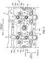
- Fig. 3 is a plan view illustrating a substantial part of the engine 1 in a state where the exhaust-side cam shaft 18 and the rocker arm 20 are removed
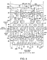
- Fig. 4 is a plan view illustrating a substantial part of the cylinder head alone.
- the cylinder head 4 has a head body 30 where the exhaust port 12, the intake port (not illustrated), etc. are formed (an example of a "bottom wall part" of the present disclosure).
- a central wall part 32 extending in the front-and-rear direction (or a longitudinal direction of the engine 1 or the cam shaft 18) so as to pass through the center of each cylinder bore 7 in the plan view
- an exhaust-side wall part 34 extending in the front-and-rear direction at a position separated from the central wall part 32 to the exhaust side
- an intake-side wall part 36 extending in the front-and-rear direction at a position separated from the central wall part 32 to the intake side (see e.g. Fig.
- a plurality of partition wall parts 38 each extending in the width direction at a plurality of positions in the front-and-rear direction of the head body 30, covering/between the wall parts 34 and 36, are provided so as to stand. Therefore, one or a plurality of cam chambers 40, which are the spaces where the rocker arm 20, etc. are disposed, are formed in the upper part of the cylinder head 4 in a grid shape.
- a plurality of exhaust-side cam chambers 40A of substantially square shapes in the plan view lined up in the front-and-rear direction, and one or a plurality of intake-side cam chambers 40B (the same number as the exhaust-side cam chambers 40A) of substantially square shapes in the plan view lined up in the front-and-rear direction, are formed in two rows.
- the exhaust-side cam shaft 18 is disposed above each exhaust-side cam chamber 40A so as to extend in the front-and-rear direction.
- the exhaust-side cam shaft 18 is supported via an oil film by a support recess 38a formed in an upper surface of each partition wall part 38, and is rotatably held by a cam shaft cap 37 and the partition wall part 38.
- the intake-side cam shaft is disposed above each intake-side cam chamber 40B so as to extend in the front-and-rear direction. Similar to the exhaust-side cam shaft 18, the intake-side cam shaft is rotatably held by the cam shaft cap 37 and the partition wall part 38.
- a bolt hole 44 and a valve hole 46 are formed in an inner bottom surface 42a of the exhaust-side cam chamber 40A.
- the bolt hole 44 is a hole into which a head bolt B for fastening the cylinder head 4 with the cylinder block 5 is inserted
- the valve hole 46 is a hole into which the exhaust valve 14 is inserted.
- the bolt hole 44 is formed substantially in the central part of the inner bottom surface 42a. As illustrated in Fig. 6 , the bolt hole 44 penetrates the head body 30 in the thickness direction (the vertical direction in Fig. 6 ).
- the head bolt B is inserted in this bolt hole 44 from the exhaust-side cam chamber 40A side, or from above.
- the head bolt B is inserted into and threadedly engaged with a nut member embedded in the cylinder block 5 or a threaded hole formed in the cylinder block 5. Therefore, the cylinder head 4 is integrally fastened with the cylinder block 5 via a gasket (not illustrated).
- a seat surface part 44a of annular in the plan view is formed around the bolt hole 44 so as to be bulged (protruded) inward of the chamber.
- a head Bh of the head bolt B is received.
- the valve holes 46 are formed particularly at respective corner parts of the exhaust-side cam chamber 40A, in detail, at respective corner parts closer to the central wall part 32.
- the exhaust valve 14 is inserted in each valve hole 46 through a cylindrical valve guide 15 (see Fig. 1 ).
- a valve stem 14a (see Fig. 1 ) of the exhaust valve 14 is inserted therein.
- each cylinder (cylinder bore 7) of the engine 1 is particularly set at a position where the central wall part 32 and the partition wall part 38 intersect in the plan view of the cylinder head 4. Therefore, the two exhaust valves 14 which open and/or close the two exhaust ports 12 of the same cylinder are inserted in the valve holes 46 of the exhaust-side cam chamber 40A which are adjacent to each other in the front-and-rear direction on both sides of the partition wall part 38. That is, the exhaust valves 14 of the cylinders which are adjacent to each other are inserted into the front and rear, two valve holes 46 which are formed in the same exhaust-side cam chamber 40A.
- a protrusion 48 is formed in a side surface 42b (an example of an "internal surface” of the present disclosure) of the exhaust-side cam chamber 40A, which is formed by the exhaust-side wall part 34 (an example of a “side wall part” of the present disclosure), so as to protrude inwardly of the cam chamber from the side surface 42b at a position separated upwardly from the inner bottom surface 42a and extend in the front-and-rear direction.
- Support holes 50 for the HLA 24 are formed particularly at both ends of the protrusion 48 in the front-and-rear direction, i.e., in corner parts of the exhaust-side cam chamber 40A, in detail, in corner parts closer to the exhaust-side wall part 34. These support holes 50 penetrate in the thickness direction of the protrusion 48 (in the height direction of the exhaust-side wall part 34), and the HLA 24 is fitted into these support holes 50.
- the HLA 24 has a configuration in which a plunger 24b which receives a load from the rocker arm 20 is accommodated in a body 24a of a cylinder shape with a bottom so as to freely appear and disappear (slide).
- the body 24a is fitted into the support holes 50 and a lower-end part of this body 24a is received by the inner bottom surface 42a of the exhaust-side cam chamber 40A, thereby supporting the HLA 24 by the protrusion 48.
- a seat surface part 50a for the HLA 24 of a circular recess is formed particularly at a position of the inner bottom surface 42a of the exhaust-side cam chamber 40A, which corresponds to each support hole 50, and a lower-end part of the HLA 24 (body 24a) is received by this seat surface part 50a.
- an oil passage 49 is formed inside the protrusion 48 so as to extend in the front-and-rear direction.
- This oil passage 49 communicates with the support hole 50 through a communication passage 49a.
- a hydraulic hole (not illustrated) is formed at a position of the body 24a of the HLA 24 corresponding to the communication passage 49a.
- a part of the side surface 42b of the exhaust-side cam chamber 40A, which faces a space between the protrusion 48 and the inner bottom surface 42a, is recessed outwardly, i.e., in a direction along the inner bottom surface 42a heading away from the bolt hole 44 (seat surface part 44a).
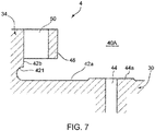
- the recessed part (referred to as a "recess 421") of the side surface 42b has a curved shape in the cross-section, and in this example, as illustrated in Fig. 1 , it has a semicircular shape (arc shape) in the cross-section. Therefore, stress resulting from fastening the head bolt B is further eased, as described later.
- the structure of the exhaust-side cam chamber 40A of the cylinder head 4 is mainly described, the structure of the intake-side cam chamber 40B is fundamentally common to the structure of the exhaust-side cam chamber 40A because it is simply symmetrical with the exhaust-side cam chamber 40A with respect to the central wall part 32, as illustrated in Fig. 4 .
- a bolt hole 44 and a seat surface part 44a for the head bolt, two valve holes 46 for the intake valves, and two seat surface parts 50a for the HLA 24 are formed in the inner bottom surface 42a of the intake-side cam chamber 40B.
- the protrusion 48 which protrudes from the side surface 42c toward the inward of the cam chamber at a position separated upwardly from the inner bottom surface 42a and extends in the front-and-rear direction, is formed, and support holes 50 for the HLA 24 are formed at both ends of the protrusion 48 in the front and rear directions.
- the HLA 24 is supported by the protrusion 48 while being fitted into the support hole 50, and oil pressure for operation is supplied to the HLA 24 through the oil passage 49 formed inside the protrusion 48.
- a part of the side surface 42c of the intake-side cam chamber 40B, which faces a space between the protrusion 48 and the inner bottom surface 42a, is recessed outwardly (downwardly and outwardly in Fig. 4 ).
- This recessed part (recess 421) has a curved shape in the cross-section, and in this example, it has a semicircle shape (arc shape) in the cross-section, similar to the recess 421 of the exhaust-side cam chamber 40A.
- the cylinder head 4 is fastened to the cylinder block 5 with the head bolts B, and the HLA 24 for pivotably supporting the rocker arm 20 is incorporated into the cylinder head 4.
- the cylinder head 4 includes the head body 30 which forms the inner bottom surfaces 42a of the exhaust-side cam chambers 40A (intake-side cam chambers 40B), and the exhaust-side wall part 34 (intake-side wall part 36) which forms the side surfaces 42b (side surfaces 42c) which rise continuously from the inner bottom surfaces 42a.
- the bolt hole 44 into which the head bolt B is inserted is formed in the inner bottom surface 42a.
- the exhaust-side wall part 34 (intake-side wall part 36) of the cylinder head 4 has the protrusion 48 which protrudes toward the inside of the cam chamber 40A (40B) from the side surface 42b (side surface 42c) at the position separated from the inner bottom surface 42a along the side surface 42b (side surface 42c), and the support hole 50 which can support the HLA 24 is formed in the protrusion 48.
- the protrusion 48 since the part of the exhaust-side wall part 34 (intake-side wall part 36) at which the HLA 24 is supported (i.e., the protrusion 48) is separated from the inner bottom surface 42a of the exhaust-side cam chamber 40A (intake-side cam chamber 40B), the generated position of the stress resulting from the deformation of the inner bottom surface 42a caused by fastening of the head bolt B separates from the fastening position of the head bolt B (the bolt hole 44 and the seat surface part 44a) by the separated amount of the protrusion 48. Therefore, according to the cylinder head 4, the stress is eased, compared with the cylinder head of the conventional structure, thereby reducing the generation of a crack, etc., in the cylinder head 4.
- Fig. 7 is a cross-sectional view of the cylinder head 4 of the embodiment (the cross-sectional view taken along the line VII-VII in Fig. 4 ), and Fig. 9 is a cross-sectional view of a cylinder head 4' according to a comparative example corresponding to the cross-sectional view taken along the line VII-VII in Fig. 4 .
- the cylinder head 4 illustrated in Fig. 7 has the structure as already described. That is, the bolt hole 44 and the seat surface part 44a of the head bolt B are formed in the inner bottom surface 42a of the exhaust-side cam chamber 40A, and the protrusion 48 having the support hole 50 for supporting the HLA 24 is protruded from the exhaust-side wall part 34 (side surface 42b). Moreover, the recess 421 is particularly formed in the part of the side surface 42b, which faces the space between the inner bottom surface 42a and the protrusion 48.
- the cylinder head 4' of the comparative example illustrated in Fig. 9 assumes the cylinder head of the conventional structure. That is, in this cylinder head 4', the protrusion 48 is partially coupled to the inner bottom surface 42a of the exhaust-side cam chamber 40A, and the recess 421 as illustrated in Fig. 7 is not formed in the exhaust-side wall part 34. Note that other structures of the cylinder head 4' are common to the cylinder head 4 of Fig. 7 .
- the protrusion 48 is not coupled to the inner bottom surface 42a.
- the recess 421 of the semicircular shape (arc shape) in the cross-section which is recessed so as to be separated from the bolt hole 44 (head bolt B), is formed in the part of the side surface 42b of the exhaust-side wall part 34, which faces the space between the protrusion 48 and the inner bottom surface 42a.
- the position at which the rigidity difference occurs i.e., the boundary part P2 of the rigidity difference
- the distance L from the depression starting point P1 to the boundary part P2 becomes larger than the distance L of the cylinder head 4' of the comparative example.
- the magnitude of the stress caused at the boundary part P2 becomes larger as the depressed amount H relatively increases and becomes larger as the distance L is relatively shortened. Therefore, if the fastening torque of the head bolt B is the same, the stress caused at the boundary part P2 becomes smaller (eased) in the cylinder head 4 of this embodiment in which the distance L from the depression starting point P1 to the boundary part P2 becomes longer, compared with the cylinder head 4' of the comparative example. Therefore, according to the cylinder head 4 of this embodiment, it can be said that the generation of a crack, etc. resulting from the fastening of the head bolts B can be reduced, compared with the cylinder head of the conventional structure.
- the cylinder head 4 As described above, although the cylinder head 4 according to the embodiment of the present disclosure is described, the cylinder head 4 described above is an illustration of a desirable embodiment of the cylinder head according to the present disclosure, and its specific structure may suitably be changed without departing from the spirit of the present disclosure.
- the cylinder head 4 may be structured as follows.
- the recess 421 of the semicircular shape (arc shape) in the cross-section is formed in the part of the side surface 42b of the exhaust-side wall part 34 which forms the exhaust-side cam chamber 40A, which faces the space between the inner bottom surface 42a and the protrusion 48.
- the cross-sectional shape of the recess 421 is not limited to the arc shape and may be any curved cross-sectional shapes other than the arc shape.
- the recess 421 may have any shapes other than the curved cross-sectional shape, in detail, may have a rectangular or triangular cross-sectional shape (a cross-sectional shape with a corner part).
- Fig. 11 illustrates one example in which a square cross-sectional shape is adopted as a recess 421. In this case, the connection part of the deep end surface of the recess 421 and the inner bottom surface 42a becomes the boundary part P2 of the rigidity difference.
- the recess 421 is formed in the side surface 42b of the exhaust-side wall part 34 which forms the exhaust-side cam chamber 40A, the recess 421 may be eliminated as illustrated in Fig. 12 .
- the connection part of the side surface 42b of the exhaust-side cam chamber 40A and the inner bottom surface 42a becomes the boundary part P2 of the rigidity difference.
- the distance L from the depression starting point P1 to the boundary part P2 becomes longer than the conventional cylinder head (see Figs. 9 and 10 ). Therefore, the stress resulting from the fastening of the head bolt B can be eased also by the structure of the cylinder head 4 illustrated in Fig. 12 , thereby reducing the generation of a crack, etc.
- the HLA 24 is applied as the pivot member which pivotably supports the rocker arm 20.
- the present disclosure can be applied also to cylinder heads in which the pivot member other than the HLA 24 is incorporated, and therefore, operation and effects equivalent to the cylinder head 4 of this embodiment can be expected from this application.
Landscapes
- Engineering & Computer Science (AREA)
- Mechanical Engineering (AREA)
- General Engineering & Computer Science (AREA)
- Chemical & Material Sciences (AREA)
- Combustion & Propulsion (AREA)
- Valve-Gear Or Valve Arrangements (AREA)
- Cylinder Crankcases Of Internal Combustion Engines (AREA)
- Lubrication Of Internal Combustion Engines (AREA)
Applications Claiming Priority (1)
| Application Number | Priority Date | Filing Date | Title |
|---|---|---|---|
| JP2019099540A JP7322514B2 (ja) | 2019-05-28 | 2019-05-28 | シリンダヘッド |
Publications (2)
| Publication Number | Publication Date |
|---|---|
| EP3744953A1 true EP3744953A1 (de) | 2020-12-02 |
| EP3744953B1 EP3744953B1 (de) | 2023-01-25 |
Family
ID=69784092
Family Applications (1)
| Application Number | Title | Priority Date | Filing Date |
|---|---|---|---|
| EP20161690.1A Active EP3744953B1 (de) | 2019-05-28 | 2020-03-09 | Zylinderkopf und motor |
Country Status (4)
| Country | Link |
|---|---|
| US (1) | US11092044B2 (de) |
| EP (1) | EP3744953B1 (de) |
| JP (1) | JP7322514B2 (de) |
| CN (1) | CN112012842B (de) |
Citations (8)
| Publication number | Priority date | Publication date | Assignee | Title |
|---|---|---|---|---|
| US4621597A (en) * | 1983-10-04 | 1986-11-11 | Honda Giken Kogyo Kabushiki Kaisha | Cylinder head for double overhead cam engine |
| JPS61277805A (ja) * | 1985-06-03 | 1986-12-08 | Honda Motor Co Ltd | 内燃機関の動弁装置 |
| US4709667A (en) * | 1985-05-14 | 1987-12-01 | Honda Giken Kogyo Kabushiki Kaisha | Oil supply device for valve operating system having hydraulic tappet in internal combustion engine |
| JPS6338667A (ja) * | 1986-08-01 | 1988-02-19 | Mazda Motor Corp | Dohcエンジンのシリンダヘツド構造 |
| JPS63176612A (ja) * | 1987-01-14 | 1988-07-20 | Daihatsu Motor Co Ltd | Dohc型内燃機関用シリンダヘツドにおける給油装置 |
| DE19852158A1 (de) * | 1998-11-12 | 2000-05-25 | Daimler Chrysler Ag | Brennkraftmaschine mit einem Kurbelgehäuse und mit wenigstens einem Zylinderkopf |
| JP2006046139A (ja) * | 2004-08-03 | 2006-02-16 | Toyota Motor Corp | シリンダヘッド |
| JP2018059439A (ja) | 2016-10-05 | 2018-04-12 | マツダ株式会社 | 油圧供給装置 |
Family Cites Families (33)
| Publication number | Priority date | Publication date | Assignee | Title |
|---|---|---|---|---|
| DE2013283C3 (de) * | 1970-03-20 | 1974-05-02 | Bayerische Motoren Werke Ag, 8000 Muenchen | Zylinderkopf für Mehrzylinder-Viertakt-Brennkraftmaschinen |
| US4644913A (en) * | 1985-10-02 | 1987-02-24 | Chrysler Motors Corporation | Recirculating valve lash adjuster |
| JPH0668256B2 (ja) * | 1986-07-09 | 1994-08-31 | 本田技研工業株式会社 | Sohc型内燃機関 |
| JP2829866B2 (ja) * | 1989-07-14 | 1998-12-02 | ヤマハ発動機株式会社 | 4サイクルエンジンの潤滑装置 |
| JPH05306603A (ja) * | 1992-04-28 | 1993-11-19 | Yamaha Motor Co Ltd | 4サイクルエンジン用動弁機構の潤滑装置 |
| JP3369036B2 (ja) * | 1995-12-26 | 2003-01-20 | ヤマハ発動機株式会社 | 頭上カム式エンジン |
| JPH1113425A (ja) * | 1997-06-26 | 1999-01-19 | Fuji Heavy Ind Ltd | ロッカアーム用枢支装置 |
| JP3706809B2 (ja) * | 2001-05-17 | 2005-10-19 | 本田技研工業株式会社 | 多気筒エンジン |
| MXPA03010514A (es) * | 2001-05-17 | 2004-07-01 | Honda Motor Co Ltd | Motor tipo sohc. |
| US6796281B2 (en) * | 2001-11-19 | 2004-09-28 | Honda Giken Kogyo Kabushiki Kaisha | Internal combustion engine with valve train |
| JP4052964B2 (ja) * | 2003-03-19 | 2008-02-27 | 本田技研工業株式会社 | ロッカーアーム軸の回り止め装置 |
| US7484484B2 (en) * | 2006-03-14 | 2009-02-03 | Gm Global Technology Operations, Inc. | Cylinder deactivation apparatus incorporating a distributed accumulator |
| US7464677B2 (en) * | 2006-05-15 | 2008-12-16 | Gm Global Technology Operations, Inc. | Compact lash adjuster feed channel apparatus |
| JP4825631B2 (ja) * | 2006-09-19 | 2011-11-30 | 株式会社オティックス | カムハウジング |
| JP4270314B2 (ja) * | 2007-09-27 | 2009-05-27 | 三菱自動車工業株式会社 | シリンダヘッド |
| JP4270313B2 (ja) * | 2007-09-27 | 2009-05-27 | 三菱自動車工業株式会社 | シリンダヘッド |
| JP2009243401A (ja) * | 2008-03-31 | 2009-10-22 | Honda Motor Co Ltd | 4サイクルエンジンにおけるシリンダヘッド構造 |
| JP2011163302A (ja) * | 2010-02-15 | 2011-08-25 | Otics Corp | 動弁装置及び支持部材 |
| US8534251B2 (en) * | 2010-05-17 | 2013-09-17 | GM Global Technology Operations LLC | Engine assembly with camshaft housing |
| JP5415363B2 (ja) * | 2010-06-11 | 2014-02-12 | 本田技研工業株式会社 | 内燃機関のシリンダヘッド構造 |
| JP5924999B2 (ja) * | 2012-03-22 | 2016-05-25 | 本田技研工業株式会社 | ロッカーアームシャフト支持部のエア抜き構造 |
| JP2014062479A (ja) * | 2012-09-20 | 2014-04-10 | Suzuki Motor Corp | エンジンの給油構造 |
| JP6146648B2 (ja) * | 2013-01-10 | 2017-06-14 | スズキ株式会社 | エンジンのシリンダヘッド |
| JP5759524B2 (ja) * | 2013-09-27 | 2015-08-05 | 本田技研工業株式会社 | 内燃機関 |
| WO2016052730A1 (ja) * | 2014-10-03 | 2016-04-07 | ヤマハ発動機株式会社 | エンジンの動弁装置 |
| US10060385B2 (en) * | 2015-02-11 | 2018-08-28 | Ford Global Technologies, Llc | Hybrid composite cylinder head |
| JP6308229B2 (ja) * | 2016-02-23 | 2018-04-11 | マツダ株式会社 | エンジンのオイル供給制御装置 |
| JP6637357B2 (ja) * | 2016-03-28 | 2020-01-29 | 本田技研工業株式会社 | パワーユニット |
| JP2017219018A (ja) * | 2016-06-10 | 2017-12-14 | 本田技研工業株式会社 | 内燃機関の動弁機構 |
| EP3505742A4 (de) * | 2016-10-28 | 2019-09-25 | Mazda Motor Corporation | Steuerungsvorrichtung eines motors mit variablem ventilsteuerungsmechanismus |
| US10450902B2 (en) * | 2016-12-02 | 2019-10-22 | GT Technologies | Finger follower assembly for use in a valvetrain of an internal combustion engine |
| JP6370874B2 (ja) * | 2016-12-27 | 2018-08-08 | 本田技研工業株式会社 | 内燃機関の可変動弁装置 |
| US10927714B2 (en) * | 2018-12-14 | 2021-02-23 | Deere & Company | Valve train with switchable engine braking |
-
2019
- 2019-05-28 JP JP2019099540A patent/JP7322514B2/ja active Active
-
2020
- 2020-02-05 US US16/782,340 patent/US11092044B2/en active Active
- 2020-03-09 EP EP20161690.1A patent/EP3744953B1/de active Active
- 2020-03-19 CN CN202010197627.6A patent/CN112012842B/zh active Active
Patent Citations (8)
| Publication number | Priority date | Publication date | Assignee | Title |
|---|---|---|---|---|
| US4621597A (en) * | 1983-10-04 | 1986-11-11 | Honda Giken Kogyo Kabushiki Kaisha | Cylinder head for double overhead cam engine |
| US4709667A (en) * | 1985-05-14 | 1987-12-01 | Honda Giken Kogyo Kabushiki Kaisha | Oil supply device for valve operating system having hydraulic tappet in internal combustion engine |
| JPS61277805A (ja) * | 1985-06-03 | 1986-12-08 | Honda Motor Co Ltd | 内燃機関の動弁装置 |
| JPS6338667A (ja) * | 1986-08-01 | 1988-02-19 | Mazda Motor Corp | Dohcエンジンのシリンダヘツド構造 |
| JPS63176612A (ja) * | 1987-01-14 | 1988-07-20 | Daihatsu Motor Co Ltd | Dohc型内燃機関用シリンダヘツドにおける給油装置 |
| DE19852158A1 (de) * | 1998-11-12 | 2000-05-25 | Daimler Chrysler Ag | Brennkraftmaschine mit einem Kurbelgehäuse und mit wenigstens einem Zylinderkopf |
| JP2006046139A (ja) * | 2004-08-03 | 2006-02-16 | Toyota Motor Corp | シリンダヘッド |
| JP2018059439A (ja) | 2016-10-05 | 2018-04-12 | マツダ株式会社 | 油圧供給装置 |
Also Published As
| Publication number | Publication date |
|---|---|
| CN112012842B (zh) | 2022-04-29 |
| US11092044B2 (en) | 2021-08-17 |
| JP7322514B2 (ja) | 2023-08-08 |
| CN112012842A (zh) | 2020-12-01 |
| US20200378279A1 (en) | 2020-12-03 |
| EP3744953B1 (de) | 2023-01-25 |
| JP2020193591A (ja) | 2020-12-03 |
Similar Documents
| Publication | Publication Date | Title |
|---|---|---|
| US5546899A (en) | Valve train load transfer device for use with hydraulic roller lifters | |
| US7677219B2 (en) | Cylinder head | |
| CN110725726B (zh) | 具有多功能盖的气门机构枢轴支架组件 | |
| EP3744953B1 (de) | Zylinderkopf und motor | |
| US20130032107A1 (en) | Multi-cylinder internal combustion engine with a system for variable actuation of the intake valves and an injector housing having a raised sealing edge | |
| US9133766B2 (en) | Internal combustion engine | |
| JP2921459B2 (ja) | エンジンのインジェクタ取付構造 | |
| US8662034B2 (en) | Multi-cylinder internal combustion engine with a system for variable actuation of the intake valves subdivided into separate sub-units | |
| US6615781B2 (en) | Overhead camshaft type valve train for internal combustion engine | |
| US20030005902A1 (en) | Four-stroke internal combustion engine cylinder head | |
| CN201614985U (zh) | 一种顶置凸轮轴发动机的分体缸头结构 | |
| JP2013113158A (ja) | 内燃機関のヘッドカバー構造 | |
| CN108049981B (zh) | 气缸盖及具有其的发动机和车辆 | |
| US20090031982A1 (en) | Oil communication manifold for an internal combustion engine | |
| JPH11257089A (ja) | 直噴式ディーゼル機関 | |
| US20180320562A1 (en) | Cylinder head structure for internal combustion engine and internal combustion engine | |
| CN111305970B (zh) | 气缸盖 | |
| CN203783741U (zh) | 发动机一体式机体 | |
| US20190211716A1 (en) | A Cylinder Head With Valve Deactivators | |
| US9169799B2 (en) | Engine cylinder head provided with light valve spring bosses | |
| US6899065B2 (en) | Radial-valve gear apparatus for barrel engine | |
| JP2000337152A (ja) | ディーゼルエンジンのシリンダヘッド | |
| JP2000337151A (ja) | ディーゼルエンジンの頭上弁型シリンダヘッド | |
| JPH11107854A (ja) | 内燃機関 | |
| JP2001193551A (ja) | エンジンのシリンダヘッド |
Legal Events
| Date | Code | Title | Description |
|---|---|---|---|
| PUAI | Public reference made under article 153(3) epc to a published international application that has entered the european phase |
Free format text: ORIGINAL CODE: 0009012 |
|
| STAA | Information on the status of an ep patent application or granted ep patent |
Free format text: STATUS: THE APPLICATION HAS BEEN PUBLISHED |
|
| AK | Designated contracting states |
Kind code of ref document: A1 Designated state(s): AL AT BE BG CH CY CZ DE DK EE ES FI FR GB GR HR HU IE IS IT LI LT LU LV MC MK MT NL NO PL PT RO RS SE SI SK SM TR |
|
| AX | Request for extension of the european patent |
Extension state: BA ME |
|
| STAA | Information on the status of an ep patent application or granted ep patent |
Free format text: STATUS: REQUEST FOR EXAMINATION WAS MADE |
|
| 17P | Request for examination filed |
Effective date: 20210512 |
|
| RBV | Designated contracting states (corrected) |
Designated state(s): AL AT BE BG CH CY CZ DE DK EE ES FI FR GB GR HR HU IE IS IT LI LT LU LV MC MK MT NL NO PL PT RO RS SE SI SK SM TR |
|
| STAA | Information on the status of an ep patent application or granted ep patent |
Free format text: STATUS: EXAMINATION IS IN PROGRESS |
|
| 17Q | First examination report despatched |
Effective date: 20211005 |
|
| GRAP | Despatch of communication of intention to grant a patent |
Free format text: ORIGINAL CODE: EPIDOSNIGR1 |
|
| STAA | Information on the status of an ep patent application or granted ep patent |
Free format text: STATUS: GRANT OF PATENT IS INTENDED |
|
| INTG | Intention to grant announced |
Effective date: 20221006 |
|
| GRAS | Grant fee paid |
Free format text: ORIGINAL CODE: EPIDOSNIGR3 |
|
| GRAA | (expected) grant |
Free format text: ORIGINAL CODE: 0009210 |
|
| STAA | Information on the status of an ep patent application or granted ep patent |
Free format text: STATUS: THE PATENT HAS BEEN GRANTED |
|
| AK | Designated contracting states |
Kind code of ref document: B1 Designated state(s): AL AT BE BG CH CY CZ DE DK EE ES FI FR GB GR HR HU IE IS IT LI LT LU LV MC MK MT NL NO PL PT RO RS SE SI SK SM TR |
|
| REG | Reference to a national code |
Ref country code: GB Ref legal event code: FG4D |
|
| REG | Reference to a national code |
Ref country code: CH Ref legal event code: EP |
|
| REG | Reference to a national code |
Ref country code: DE Ref legal event code: R096 Ref document number: 602020007747 Country of ref document: DE |
|
| REG | Reference to a national code |
Ref country code: AT Ref legal event code: REF Ref document number: 1546059 Country of ref document: AT Kind code of ref document: T Effective date: 20230215 Ref country code: IE Ref legal event code: FG4D |
|
| REG | Reference to a national code |
Ref country code: LT Ref legal event code: MG9D |
|
| REG | Reference to a national code |
Ref country code: NL Ref legal event code: MP Effective date: 20230125 |
|
| REG | Reference to a national code |
Ref country code: AT Ref legal event code: MK05 Ref document number: 1546059 Country of ref document: AT Kind code of ref document: T Effective date: 20230125 |
|
| PG25 | Lapsed in a contracting state [announced via postgrant information from national office to epo] |
Ref country code: NL Free format text: LAPSE BECAUSE OF FAILURE TO SUBMIT A TRANSLATION OF THE DESCRIPTION OR TO PAY THE FEE WITHIN THE PRESCRIBED TIME-LIMIT Effective date: 20230125 |
|
| PG25 | Lapsed in a contracting state [announced via postgrant information from national office to epo] |
Ref country code: RS Free format text: LAPSE BECAUSE OF FAILURE TO SUBMIT A TRANSLATION OF THE DESCRIPTION OR TO PAY THE FEE WITHIN THE PRESCRIBED TIME-LIMIT Effective date: 20230125 Ref country code: PT Free format text: LAPSE BECAUSE OF FAILURE TO SUBMIT A TRANSLATION OF THE DESCRIPTION OR TO PAY THE FEE WITHIN THE PRESCRIBED TIME-LIMIT Effective date: 20230525 Ref country code: NO Free format text: LAPSE BECAUSE OF FAILURE TO SUBMIT A TRANSLATION OF THE DESCRIPTION OR TO PAY THE FEE WITHIN THE PRESCRIBED TIME-LIMIT Effective date: 20230425 Ref country code: LV Free format text: LAPSE BECAUSE OF FAILURE TO SUBMIT A TRANSLATION OF THE DESCRIPTION OR TO PAY THE FEE WITHIN THE PRESCRIBED TIME-LIMIT Effective date: 20230125 Ref country code: LT Free format text: LAPSE BECAUSE OF FAILURE TO SUBMIT A TRANSLATION OF THE DESCRIPTION OR TO PAY THE FEE WITHIN THE PRESCRIBED TIME-LIMIT Effective date: 20230125 Ref country code: HR Free format text: LAPSE BECAUSE OF FAILURE TO SUBMIT A TRANSLATION OF THE DESCRIPTION OR TO PAY THE FEE WITHIN THE PRESCRIBED TIME-LIMIT Effective date: 20230125 Ref country code: ES Free format text: LAPSE BECAUSE OF FAILURE TO SUBMIT A TRANSLATION OF THE DESCRIPTION OR TO PAY THE FEE WITHIN THE PRESCRIBED TIME-LIMIT Effective date: 20230125 Ref country code: AT Free format text: LAPSE BECAUSE OF FAILURE TO SUBMIT A TRANSLATION OF THE DESCRIPTION OR TO PAY THE FEE WITHIN THE PRESCRIBED TIME-LIMIT Effective date: 20230125 |
|
| PG25 | Lapsed in a contracting state [announced via postgrant information from national office to epo] |
Ref country code: SE Free format text: LAPSE BECAUSE OF FAILURE TO SUBMIT A TRANSLATION OF THE DESCRIPTION OR TO PAY THE FEE WITHIN THE PRESCRIBED TIME-LIMIT Effective date: 20230125 Ref country code: PL Free format text: LAPSE BECAUSE OF FAILURE TO SUBMIT A TRANSLATION OF THE DESCRIPTION OR TO PAY THE FEE WITHIN THE PRESCRIBED TIME-LIMIT Effective date: 20230125 Ref country code: IS Free format text: LAPSE BECAUSE OF FAILURE TO SUBMIT A TRANSLATION OF THE DESCRIPTION OR TO PAY THE FEE WITHIN THE PRESCRIBED TIME-LIMIT Effective date: 20230525 Ref country code: GR Free format text: LAPSE BECAUSE OF FAILURE TO SUBMIT A TRANSLATION OF THE DESCRIPTION OR TO PAY THE FEE WITHIN THE PRESCRIBED TIME-LIMIT Effective date: 20230426 Ref country code: FI Free format text: LAPSE BECAUSE OF FAILURE TO SUBMIT A TRANSLATION OF THE DESCRIPTION OR TO PAY THE FEE WITHIN THE PRESCRIBED TIME-LIMIT Effective date: 20230125 |
|
| REG | Reference to a national code |
Ref country code: DE Ref legal event code: R097 Ref document number: 602020007747 Country of ref document: DE |
|
| PG25 | Lapsed in a contracting state [announced via postgrant information from national office to epo] |
Ref country code: SM Free format text: LAPSE BECAUSE OF FAILURE TO SUBMIT A TRANSLATION OF THE DESCRIPTION OR TO PAY THE FEE WITHIN THE PRESCRIBED TIME-LIMIT Effective date: 20230125 Ref country code: RO Free format text: LAPSE BECAUSE OF FAILURE TO SUBMIT A TRANSLATION OF THE DESCRIPTION OR TO PAY THE FEE WITHIN THE PRESCRIBED TIME-LIMIT Effective date: 20230125 Ref country code: MC Free format text: LAPSE BECAUSE OF FAILURE TO SUBMIT A TRANSLATION OF THE DESCRIPTION OR TO PAY THE FEE WITHIN THE PRESCRIBED TIME-LIMIT Effective date: 20230125 Ref country code: EE Free format text: LAPSE BECAUSE OF FAILURE TO SUBMIT A TRANSLATION OF THE DESCRIPTION OR TO PAY THE FEE WITHIN THE PRESCRIBED TIME-LIMIT Effective date: 20230125 Ref country code: DK Free format text: LAPSE BECAUSE OF FAILURE TO SUBMIT A TRANSLATION OF THE DESCRIPTION OR TO PAY THE FEE WITHIN THE PRESCRIBED TIME-LIMIT Effective date: 20230125 Ref country code: CZ Free format text: LAPSE BECAUSE OF FAILURE TO SUBMIT A TRANSLATION OF THE DESCRIPTION OR TO PAY THE FEE WITHIN THE PRESCRIBED TIME-LIMIT Effective date: 20230125 |
|
| REG | Reference to a national code |
Ref country code: CH Ref legal event code: PL |
|
| PG25 | Lapsed in a contracting state [announced via postgrant information from national office to epo] |
Ref country code: SK Free format text: LAPSE BECAUSE OF FAILURE TO SUBMIT A TRANSLATION OF THE DESCRIPTION OR TO PAY THE FEE WITHIN THE PRESCRIBED TIME-LIMIT Effective date: 20230125 |
|
| REG | Reference to a national code |
Ref country code: BE Ref legal event code: MM Effective date: 20230331 |
|
| PLBE | No opposition filed within time limit |
Free format text: ORIGINAL CODE: 0009261 |
|
| STAA | Information on the status of an ep patent application or granted ep patent |
Free format text: STATUS: NO OPPOSITION FILED WITHIN TIME LIMIT |
|
| PG25 | Lapsed in a contracting state [announced via postgrant information from national office to epo] |
Ref country code: LU Free format text: LAPSE BECAUSE OF NON-PAYMENT OF DUE FEES Effective date: 20230309 |
|
| 26N | No opposition filed |
Effective date: 20231026 |
|
| REG | Reference to a national code |
Ref country code: IE Ref legal event code: MM4A |
|
| PG25 | Lapsed in a contracting state [announced via postgrant information from national office to epo] |
Ref country code: SI Free format text: LAPSE BECAUSE OF FAILURE TO SUBMIT A TRANSLATION OF THE DESCRIPTION OR TO PAY THE FEE WITHIN THE PRESCRIBED TIME-LIMIT Effective date: 20230125 Ref country code: LI Free format text: LAPSE BECAUSE OF NON-PAYMENT OF DUE FEES Effective date: 20230331 Ref country code: IE Free format text: LAPSE BECAUSE OF NON-PAYMENT OF DUE FEES Effective date: 20230309 Ref country code: FR Free format text: LAPSE BECAUSE OF NON-PAYMENT OF DUE FEES Effective date: 20230325 Ref country code: CH Free format text: LAPSE BECAUSE OF NON-PAYMENT OF DUE FEES Effective date: 20230331 |
|
| PG25 | Lapsed in a contracting state [announced via postgrant information from national office to epo] |
Ref country code: BE Free format text: LAPSE BECAUSE OF NON-PAYMENT OF DUE FEES Effective date: 20230331 |
|
| PG25 | Lapsed in a contracting state [announced via postgrant information from national office to epo] |
Ref country code: IT Free format text: LAPSE BECAUSE OF FAILURE TO SUBMIT A TRANSLATION OF THE DESCRIPTION OR TO PAY THE FEE WITHIN THE PRESCRIBED TIME-LIMIT Effective date: 20230125 |
|
| PG25 | Lapsed in a contracting state [announced via postgrant information from national office to epo] |
Ref country code: BG Free format text: LAPSE BECAUSE OF FAILURE TO SUBMIT A TRANSLATION OF THE DESCRIPTION OR TO PAY THE FEE WITHIN THE PRESCRIBED TIME-LIMIT Effective date: 20230125 |
|
| GBPC | Gb: european patent ceased through non-payment of renewal fee |
Effective date: 20240309 |
|
| PG25 | Lapsed in a contracting state [announced via postgrant information from national office to epo] |
Ref country code: BG Free format text: LAPSE BECAUSE OF FAILURE TO SUBMIT A TRANSLATION OF THE DESCRIPTION OR TO PAY THE FEE WITHIN THE PRESCRIBED TIME-LIMIT Effective date: 20230125 |
|
| PG25 | Lapsed in a contracting state [announced via postgrant information from national office to epo] |
Ref country code: GB Free format text: LAPSE BECAUSE OF NON-PAYMENT OF DUE FEES Effective date: 20240309 |
|
| PG25 | Lapsed in a contracting state [announced via postgrant information from national office to epo] |
Ref country code: GB Free format text: LAPSE BECAUSE OF NON-PAYMENT OF DUE FEES Effective date: 20240309 |
|
| PG25 | Lapsed in a contracting state [announced via postgrant information from national office to epo] |
Ref country code: CY Free format text: LAPSE BECAUSE OF FAILURE TO SUBMIT A TRANSLATION OF THE DESCRIPTION OR TO PAY THE FEE WITHIN THE PRESCRIBED TIME-LIMIT; INVALID AB INITIO Effective date: 20200309 |
|
| PG25 | Lapsed in a contracting state [announced via postgrant information from national office to epo] |
Ref country code: HU Free format text: LAPSE BECAUSE OF FAILURE TO SUBMIT A TRANSLATION OF THE DESCRIPTION OR TO PAY THE FEE WITHIN THE PRESCRIBED TIME-LIMIT; INVALID AB INITIO Effective date: 20200309 |
|
| PG25 | Lapsed in a contracting state [announced via postgrant information from national office to epo] |
Ref country code: TR Free format text: LAPSE BECAUSE OF FAILURE TO SUBMIT A TRANSLATION OF THE DESCRIPTION OR TO PAY THE FEE WITHIN THE PRESCRIBED TIME-LIMIT Effective date: 20230125 |
|
| PGFP | Annual fee paid to national office [announced via postgrant information from national office to epo] |
Ref country code: DE Payment date: 20260128 Year of fee payment: 7 |