EP3744962B1 - Procédé et dispositif de commande de moteur à combustion interne - Google Patents
Procédé et dispositif de commande de moteur à combustion interne Download PDFInfo
- Publication number
- EP3744962B1 EP3744962B1 EP18902085.2A EP18902085A EP3744962B1 EP 3744962 B1 EP3744962 B1 EP 3744962B1 EP 18902085 A EP18902085 A EP 18902085A EP 3744962 B1 EP3744962 B1 EP 3744962B1
- Authority
- EP
- European Patent Office
- Prior art keywords
- air
- operation state
- fuel ratio
- region
- intake
- Prior art date
- Legal status (The legal status is an assumption and is not a legal conclusion. Google has not performed a legal analysis and makes no representation as to the accuracy of the status listed.)
- Active
Links
Images


Classifications
-
- F—MECHANICAL ENGINEERING; LIGHTING; HEATING; WEAPONS; BLASTING
- F02—COMBUSTION ENGINES; HOT-GAS OR COMBUSTION-PRODUCT ENGINE PLANTS
- F02D—CONTROLLING COMBUSTION ENGINES
- F02D13/00—Controlling the engine output power by varying inlet or exhaust valve operating characteristics, e.g. timing
- F02D13/02—Controlling the engine output power by varying inlet or exhaust valve operating characteristics, e.g. timing during engine operation
- F02D13/0223—Variable control of the intake valves only
- F02D13/0234—Variable control of the intake valves only changing the valve timing only
-
- F—MECHANICAL ENGINEERING; LIGHTING; HEATING; WEAPONS; BLASTING
- F02—COMBUSTION ENGINES; HOT-GAS OR COMBUSTION-PRODUCT ENGINE PLANTS
- F02D—CONTROLLING COMBUSTION ENGINES
- F02D41/00—Electrical control of supply of combustible mixture or its constituents
- F02D41/0002—Controlling intake air
- F02D41/0007—Controlling intake air for control of turbo-charged or super-charged engines
-
- F—MECHANICAL ENGINEERING; LIGHTING; HEATING; WEAPONS; BLASTING
- F02—COMBUSTION ENGINES; HOT-GAS OR COMBUSTION-PRODUCT ENGINE PLANTS
- F02D—CONTROLLING COMBUSTION ENGINES
- F02D41/00—Electrical control of supply of combustible mixture or its constituents
- F02D41/02—Circuit arrangements for generating control signals
- F02D41/14—Introducing closed-loop corrections
- F02D41/1438—Introducing closed-loop corrections using means for determining characteristics of the combustion gases; Sensors therefor
- F02D41/1444—Introducing closed-loop corrections using means for determining characteristics of the combustion gases; Sensors therefor characterised by the characteristics of the combustion gases
- F02D41/1454—Introducing closed-loop corrections using means for determining characteristics of the combustion gases; Sensors therefor characterised by the characteristics of the combustion gases the characteristics being an oxygen content or concentration or the air-fuel ratio
-
- F—MECHANICAL ENGINEERING; LIGHTING; HEATING; WEAPONS; BLASTING
- F02—COMBUSTION ENGINES; HOT-GAS OR COMBUSTION-PRODUCT ENGINE PLANTS
- F02D—CONTROLLING COMBUSTION ENGINES
- F02D41/00—Electrical control of supply of combustible mixture or its constituents
- F02D41/30—Controlling fuel injection
- F02D41/3011—Controlling fuel injection according to or using specific or several modes of combustion
- F02D41/3017—Controlling fuel injection according to or using specific or several modes of combustion characterised by the mode(s) being used
- F02D41/3023—Controlling fuel injection according to or using specific or several modes of combustion characterised by the mode(s) being used a mode being the stratified charge spark-ignited mode
- F02D41/3029—Controlling fuel injection according to or using specific or several modes of combustion characterised by the mode(s) being used a mode being the stratified charge spark-ignited mode further comprising a homogeneous charge spark-ignited mode
-
- F—MECHANICAL ENGINEERING; LIGHTING; HEATING; WEAPONS; BLASTING
- F02—COMBUSTION ENGINES; HOT-GAS OR COMBUSTION-PRODUCT ENGINE PLANTS
- F02D—CONTROLLING COMBUSTION ENGINES
- F02D41/00—Electrical control of supply of combustible mixture or its constituents
- F02D41/30—Controlling fuel injection
- F02D41/3011—Controlling fuel injection according to or using specific or several modes of combustion
- F02D41/3064—Controlling fuel injection according to or using specific or several modes of combustion with special control during transition between modes
- F02D41/307—Controlling fuel injection according to or using specific or several modes of combustion with special control during transition between modes to avoid torque shocks
-
- F—MECHANICAL ENGINEERING; LIGHTING; HEATING; WEAPONS; BLASTING
- F02—COMBUSTION ENGINES; HOT-GAS OR COMBUSTION-PRODUCT ENGINE PLANTS
- F02D—CONTROLLING COMBUSTION ENGINES
- F02D41/00—Electrical control of supply of combustible mixture or its constituents
- F02D41/0002—Controlling intake air
- F02D2041/002—Controlling intake air by simultaneous control of throttle and variable valve actuation
-
- F—MECHANICAL ENGINEERING; LIGHTING; HEATING; WEAPONS; BLASTING
- F02—COMBUSTION ENGINES; HOT-GAS OR COMBUSTION-PRODUCT ENGINE PLANTS
- F02D—CONTROLLING COMBUSTION ENGINES
- F02D2200/00—Input parameters for engine control
- F02D2200/02—Input parameters for engine control the parameters being related to the engine
- F02D2200/10—Parameters related to the engine output, e.g. engine torque or engine speed
- F02D2200/101—Engine speed
Definitions
- the present invention relates to a method for controlling an internal combustion engine and to a device for controlling the internal combustion engine.
- a throttle valve is operated to be closed by a predetermined amount. Then, in order to cancel out a rapid increase in engine torque at the time when the combustion mode is switched from the stratified combustion in which the air-fuel ratio is lean to the homogeneous combustion in which the air-fuel ratio is rich, ignition timing retard and the increase correction of a fuel injection amount are carried out.
- the increase correction of the fuel injection amount is carried out by a first one combustion cycle of each cylinder after the switching of the fuel injection mode by estimating an air amount remaining in each of the cylinders in which the fuel injection mode is switched.
- the patent document 1 is not one for cancelling out a rapid increase in engine torque at the time when an operation state is changed from an operation state in which an air-fuel ratio in a supercharged state is lean to an operation state in which the air-fuel ratio in a non-supercharged state is rich.
- the patent document 1 is not one in which response delay of an intake pressure at the time when the operation state is changed from the operation state in which the air-fuel ratio in the supercharged state is lean to the operation state in which the air-fuel ratio in the non-supercharged state is rich is not considered.
- Patent document 2 discloses the control of a supercharged IC engine, which can switch between a plurality of combustion modes.
- Control means suppress a lowering of a throttle opening related to the engine, and increases a fuel amount supplied to the engine when switching from a first to a second combustion mode whose air-fuel ratio is richer than an air-fuel ratio related to the first combustion mode.
- an air amount in a cylinder is controlled such that by reducing the air amount in the cylinder so as to be an air amount smaller than an air amount realizing the rich air-fuel ratio, a torque overshoot of the internal combustion engine caused by pump work does not occur.
- FIG. 1 is an explanatory view schematically showing a control device of an internal combustion engine 1.
- internal combustion engine 1 is a spark ignition type gasoline engine, and is mounted on a vehicle, such as a car, as a driving source.
- Internal combustion engine 1 includes an intake passage 2 and an exhaust passage 3.
- Intake passage 2 is connected to a combustion chamber 6 via an intake valve 4.
- Exhaust passage 3 is connected to combustion chamber 6 via an exhaust valve 5.
- Internal combustion engine 1 has, for example, a cylinder direct injection type structure, and a fuel injection valve (not shown in the drawings) for injecting fuel into a cylinder and an ignition plug 7 are provided to each cylinder.
- the injection timing and the injection amount of the fuel injection valve and the ignition timing of ignition plug 7 are controlled by control signals from a control unit 8.
- Internal combustion engine 1 includes, as a valve mechanism of intake valve 4, an intake-side variable valve mechanism 10 which is capable of varying the valve timing (opening-closing timing) of intake valve 4.
- a valve mechanism on an exhaust valve side is a general direct-acting valve mechanism, and the phases of the lift operation angle and the lift central angle of exhaust valve 5 are always constant.
- intake-side variable valve mechanism 10 is one driven with hydraulic pressure, and is controlled by control signals from control unit 8. That is, control unit 8 corresponds to a control unit configured to control intake-side variable valve mechanism 10. Then, by control unit 8, the valve timing of intake valve 4 can be variably controlled. Intake-side variable valve mechanism 10 is configured so as to be capable of controlling the air amount in a cylinder by controlling the valve closing timing of intake valve 4. For example, in a case where the intake valve closing timing is delayed from the bottom dead center, the intake valve closing timing is delayed so as to be away from the bottom dead center, and thereby the air amount in a cylinder can be reduced.
- intake-side variable valve mechanism 10 corresponds to an air amount control unit which is capable of variably controlling the air amount in a cylinder.
- Intake-side variable valve mechanism 10 may be one which is capable of individually independently varying the opening timing and the closing timing of intake valve 4, or may be one which is capable of simultaneously delaying or advancing the opening timing and the closing timing. In the present embodiment, the latter one which delays or advances the phase of an intake-side camshaft 11 to a crankshaft 12 is used.
- intake-side variable valve mechanism 10 is not limited to one which is driven with hydraulic pressure, it may be one which is electrically driven by, for example, a motor.
- intake valve 4 The valve timing of intake valve 4 is detected by an intake-side camshaft position sensor 13.
- Intake-side camshaft position sensor 13 is one to detect the phase of intake-side camshaft 11 to crankshaft 12.
- Intake passage 2 is provided with an air cleaner 16 for collecting foreign matters in the intake air, an air flow meter 17 for detecting the amount of the intake air, and with an electric throttle valve 18 capable of controlling the intake air amount in a cylinder.
- Air flow meter 17 includes thereinside a temperature sensor, so as to detect (measure) the intake air temperature at an intake introducing port. Air flow meter 17 is disposed on the downstream side of air cleaner 16.
- Throttle valve 18 is one equipped with an actuator, such as an electric motor, and by a control signal from control unit 8, the opening degree of throttle valve 18 is controlled. Throttle valve 18 is disposed on the downstream side of air flow meter 17.
- throttle opening degree The opening degree of throttle valve 18 (throttle opening degree) is detected by a throttle opening sensor 19.
- the detection signal of throttle opening sensor 19 is input to control unit 8.
- Exhaust passage 3 is provided with an upstream-side exhaust catalyst 21, such as a three-way catalyst, a downstream-side exhaust catalyst 22, such as a three-way catalyst, and with a muffler 23 as a silencer to reduce exhaust sound.
- Downstream-side exhaust catalyst 22 is disposed on the downstream side of upstream-side exhaust catalyst 21.
- Muffler 23 is disposed on the downstream side of downstream-side exhaust catalyst 22.
- this internal combustion engine 1 includes a turbo supercharger 25 as a supercharger equipped with, on the same axis, a compressor 26 provided to intake passage 2 and a turbine 27 provided to exhaust passage 3.
- Compressor 26 is disposed between the upstream side of throttle valve 18 and the downstream side of air flow meter 17.
- Turbine 27 is disposed more on the upstream side than upstream-side exhaust catalyst 21.
- An intake bypass passage 30 is connected to intake passage 2.
- Intake bypass passage 30 is formed so as to communicate the upstream side to the downstream side of compressor 26 by bypassing compressor 26.
- Intake bypass passage 30 is provided with an electric recirculation valve 31.
- recirculation valve 31 is normally closed, when throttle valve 18 is closed and the downstream side of compressor 26 becomes in a high pressure state, recirculation valve 31 is opened. Recirculation valve 31 is opened, and consequently, the intake air in the high pressure state on the downstream side of compressor 26 can be returned to the upstream side of compressor 26 via intake bypass passage 30.
- Recirculation valve 31 is controlled to be opened and closed by a control signal from control unit 8.
- recirculation valve 31 not only one controlled to be opened and closed by control unit 8, but also a so-called check valve which is opened only when the pressure on the downstream side of compressor 26 becomes a predetermined pressure or higher can be used.
- intake passage 2 is provided with, on the downstream side of throttle valve 18, an intercooler 32 to improve volumetric efficiency by cooling the intake air compressed (pressurized) by compressor 26.
- Intercooler 32 is disposed in a cooling path 35 for the intercooler (sub-cooling path), together with a radiator 33 for the intercooler (intercooler radiator) and an electric pump 34. Refrigerant (cooling water) cooled by radiator 33 can be supplied to intercooler 32.
- Intercooler cooling path 35 is configured such that the refrigerant can circulate inside the path.
- Intercooler cooling path 35 is a cooling path independent of a main cooling path which is not shown in the drawings and in which cooling water for cooling a cylinder block 37 of internal combustion engine 1 circulates.
- Radiator 33 is configured to cool the refrigerant inside intercooler cooling path 35 by heat exchange with outside air.
- Electric pump 34 is one for circulating the refrigerant inside intercooler cooling path 35 in the direction shown by an arrow A by the driving thereof
- An exhaust bypass passage 38 connecting the upstream side with the downstream side of turbine 27 by bypassing turbine 27 is connected to exhaust passage 3.
- the downstream-side end of exhaust bypass passage 38 is connected to exhaust passage 3 at a position more on the upstream side than upstream-side exhaust catalyst 21.
- An electric waste gate valve 39 for controlling the flow rate of exhaust gas inside exhaust bypass passage 38 is disposed in exhaust bypass passage 38.
- internal combustion engine 1 is one which is capable of performing exhaust gas recirculation (EGR) in which, as EGR gas, a part of exhaust gas is introduced (recirculated) from exhaust passage 3 to intake passage 2, and includes an EGR passage 41 which is branched from exhaust passage 3 so as to be connected to intake passage 2.
- EGR passage 41 is connected to exhaust passage 3 at a position between the upstream-side exhaust catalyst 21 and downstream-side catalyst 22, and the other end thereof is connected to intake passage 2 at a position which is the downstream side of air flow meter 17 and is the upstream side of compressor 26.
- EGR passage 41 is provided with an electric EGR valve 42 for controlling the flow rate of the EGR gas inside EGR passage 41, and with an EGR cooler 43 which is capable of cooling the EGR gas.
- the opening-closing operation of EGR valve 42 is controlled by control unit 8 as a control unit.
- detection signals of sensors such as a crank angle sensor 45 which is capable of detecting engine speed together with the crank angle of crankshaft 12, an accelerator opening sensor 46 for detecting the depression amount of an accelerator pedal (not shown in the drawings), a supercharging pressure sensor 47 for detecting supercharging pressure, and an exhaust pressure sensor 48 for detecting exhaust pressure, are input to control unit 8.
- Supercharging pressure sensor 47 is disposed at a position more on the downstream side than intake cooler 32 in intake passage 2, for example, it is disposed in a collector part, to detect intake pressure at the disposed position.
- Exhaust pressure sensor 48 is disposed at a position more on the upstream side than turbine 27 in exhaust passage 3, to detect exhaust pressure at the disposed position.
- Control unit 8 is configured to calculate a required load (engine load) of internal combustion engine 1 by using the detection value of accelerator opening sensor 46.
- control unit 8 performs the control of the ignition timing and the air-fuel ratio of internal combustion engine 1 and the control of the exhaust gas recirculation (EGR control) in which a part of exhaust gas is recirculated from exhaust passage 3 to intake passage 2 by controlling the opening degree of EGR valve 42.
- control unit 8 also controls the driving of electric pump 34 and the opening degree of each of throttle valve 18 and waste gate valve 39.
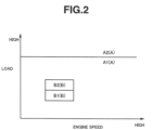
- Control unit 8 controls the air-fuel ratio of internal combustion engine 1, according to an operation state, by using an air-fuel ratio calculation map shown in FIG. 2.
- FIG. 2 is the air-fuel ratio calculation map stored in control unit 8, and the air-fuel ratio is allocated according to the engine load and the engine speed.
- Control unit 8 controls the air-fuel ratio so as to be a theoretical air-fuel ratio in a predetermined first operation region A, and in a predetermined second operation region B in which the engine speed is low and the engine load is low, the air-fuel ratio is controlled so as to be an air-fuel ratio leaner than the air-fuel ratio in first operation region A. That is, the air-fuel ratio in first operation region A corresponds to a predetermined rich air-fuel ratio, and the air-fuel ratio in second operation region B corresponds to a predetermined lean air-fuel ratio.
- a region A1 on the low load side in first operation region A is a non-supercharging region in which the supercharging by turbo supercharger 25 is not performed.
- a region A2 on the high load side in first operation region A is a supercharging region in which the supercharging by turbo supercharger 25 is performed.
- region A1 corresponds to a second operation state in which the air-fuel ratio becomes an air-fuel ratio richer than the air-fuel ratio in second operation region B in a non-supercharged state.
- a region B1 on the low load side in second operation region B is a non-supercharging region in which the supercharging by turbo supercharger 25 is not performed.
- a region B2 on the high load side in second operation region B is a supercharging region in which the supercharging by turbo supercharger 25 is performed.
- region B2 corresponds to a first operation state in which the air-fuel ratio becomes a predetermined lean air-fuel ratio in a supercharged state.
- the throttle valve 18 is moved toward the valve closing side such that the opening degree of throttle valve 18 (throttle opening degree) becomes a target throttle opening degree at the steady time in region A1, and waste gate valve 39 is fully opened.
- the opening degree of throttle valve 18 throttle opening degree
- waste gate valve 39 waste gate valve 39
- FIG. 3 is a timing chart showing changes in various parameters during the transient period in which the operation state is shifted from region B2 to region A1 in a comparative embodiment.
- the opening degree of throttle valve 18 (throttle opening degree) is varied temporarily from the steady-time target throttle valve opening degree in region A1 toward the valve closing side by a predetermined amount ⁇ P, and is thereafter controlled so as to be the stationary-time target throttle valve opening degree in region A1, such that the intake pressure becomes lower than the exhaust pressure.
- the air amount in a cylinder is reduced such that the torque overshoot in internal combustion engine 1 does not occur.
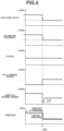
- FIG. 4 is a timing chart showing changes in parameters during the transient period in which the operation state is shifted from region B2 to region A1, in the first embodiment.
- the throttle valve opening degree is closed further from the steady-time target throttle valve opening degree in region A1 by the predetermined amount ⁇ P, the intake pressure becomes smaller than the exhaust pressure surely.
- FIG. 5 is one schematically showing a calculation map of the predetermined amount ⁇ P, to which the predetermined amount ⁇ P is allocated. This predetermined amount ⁇ P calculation map is stored in control unit 8.
- the predetermined amount ⁇ P is set so as to be larger as the supercharging pressure in region B2 is higher, and is set so as to be smaller as the engine speed of the internal combustion engine in region B2 is higher.
- the predetermined amount ⁇ P is set so as to be larger as the supercharging pressure in region B2 is higher, the intake pressure can be sufficiently reduced, and thereby the occurrence of the pump work can be surely suppressed.
- Curved lines sloped from left to right in FIG. 5 indicate the relation between the predetermined amount ⁇ P when engine speeds Ne1 to Ne4 (Ne1 ⁇ Ne2 ⁇ Ne3 ⁇ Ne4) are used as parameters and the supercharging pressure in region B2.
- FIG. 6 is a flowchart showing the flow of the control of internal combustion engine 1 in the above-mentioned first embodiment.
- a step S1 the supercharging pressure and the engine speed are read.
- step S2 it is determined whether or not the operation state is shifted from region B2 to region A1. In step S2, when it is determined that the operation state is shifted from region B2 to region A1, the process proceeds to a step S3. In step S2, when it is not determined that the operation state is shifted from region B2 to region A1, the routine this time is ended.
- step S3 the predetermined amount ⁇ P is calculated by using the supercharging pressure and the engine speed.
- a step S4 by using the predetermined amount ⁇ P, the target throttle opening degree during the transient period in which the operation state is shifted from region B2 to region A1 is corrected. That is, during the initial stage of the transient period in which the operation state is shifted from region B2 to region A1, throttle valve 18 is controlled such that the throttle opening degree temporarily becomes smaller than the steady-time target throttle opening degree in region A1 by the predetermined amount ⁇ P
- the predetermined amount ⁇ P is determined in accordance with the supercharging pressure and the engine speed
- the predetermined amount ⁇ P may be calculated by using only one of the supercharging pressure and the engine speed.
- the air amount control unit is also controlled such that the air amount in a cylinder becomes smaller than the air amount realizing a rich air-fuel ratio.
- the air amount control unit in the second embodiment is not throttle valve 18 but is intake-side variable valve mechanism 10.
- the valve closing timing of intake valve 4 is varied so as to be a target intake valve closing timing at the steady time in region A1
- the opening degree of throttle valve 18 (throttle opening degree) is varied toward the valve closing side so as to be a target throttle opening degree at the steady time in region A1
- waste gate valve 39 is fully opened.
- FIG. 7 is a timing chart showing changes in various parameters during the transient period in which the operation state is shifted from region B2 to region A1 in a comparative embodiment.
- the intake valve closing timing in FIG. 7 is shown, as an example, with a case where the steady-time target intake valve closing timing in region A1 and B2 becomes a timing after the intake bottom dead center.
- the intake valve closing timing is controlled to be temporarily varied further from the steady-time intake valve closing timing in region A1 in a direction away from the bottom dead center by a predetermined amount ⁇ Q, and is thereafter controlled so as to be the steady-time intake valve closing timing in region A1.
- the intake-side variable valve mechanism 10 temporarily advances or delays the valve timing of intake valve 4 from the stationary-time target intake valve closing timing in region A1 in a direction away from the bottom dead center.
- FIG. 8 is a timing chart showing changes in various parameters during the transient period in which the operation state is shifted from region B2 to region A1.
- intake-side variable valve mechanism 10 controls the valve timing of intake valve 4 such that the intake valve closing timing is further temporarily advanced from the steady-time target intake valve closing timing in region A1.
- intake-side variable valve mechanism 10 controls the valve timing of intake valve 4 such that the intake valve closing timing is further temporarily delayed from the steady-time target intake valve closing timing in region A1.
- the air amount in a cylinder is reduced such that the torque overshoot does not occur in internal combustion engine 1.
- the intake valve closing timing in FIG. 8 is shown, as an example, with a case where the steady-time target intake valve closing timing in region A1 and B2 becomes a timing after the intake bottom dead center.
- the intake valve closing timing is set so as to be away (separated) from the intake bottom dead center, and consequently, the amount of the intake air during the transient period in which the operation state is shifted from region B2 to region A1 is reduced, and overshoot of volumetric efficiency can be suppressed.
- the intake valve closing timing is controlled so as to be temporarily away further from the steady-time target intake valve closing timing in region A1 in the direction away from the bottom dead center by the predetermined amount ⁇ Q, and thereby overshoot of volumetric efficiency can be suppressed.
- FIG. 9 is one schematically showing a calculation map of the predetermined amount ⁇ Q, to which the predetermined amount ⁇ Q is allocated. This predetermined amount ⁇ Q calculation map is one stored in control unit 8.
- the predetermined amount ⁇ Q is set so as to be larger as the supercharging pressure in region B2 is higher, and is set so as to be smaller as the engine speed of the internal combustion engine in region B2 is higher.
- Curved lines sloped from left to right in FIG. 9 indicate the relation between the predetermined amount ⁇ Q when engine speeds Ne1 to Ne4 (Ne1 ⁇ Ne2 ⁇ Ne3 ⁇ Ne4) are used as parameters and the supercharging pressure in region B2.
- the predetermined amount ⁇ Q is set so as to be larger as the supercharging pressure in region B2 is higher, the intake pressure can be sufficiently reduced, and thereby the occurrence of the pump work can be further surely suppressed.
- the predetermined amount ⁇ Q can be set so as to be smaller as the engine speed of the internal combustion engine in region B2 is higher.
- FIG. 10 is a flowchart showing the flow of the control of internal combustion engine 1 in the above-mentioned second embodiment.
- a step S11 the supercharging pressure and the engine speed are read.
- step S12 it is determined whether or not the operation state is shifted from region B2 to region A1. In step S12, when it is determined that the operation state is shifted from region B2 to region A1, the process proceeds to a step S13. In step S12, when it is not determined that the operation state is shifted from region B2 to region A1, the routine this time is ended.
- step S13 the predetermined amount ⁇ Q is calculated by using the supercharging pressure and the engine speed.
- intake-side variable valve mechanism 10 during the transient period in which the operation state is shifted from region B2 to region A1 is controlled by using the predetermined amount ⁇ Q. That is, during the initial stage of the transient period in which the operation state is shifted from region B2 to region A1, intake-side variable valve mechanism 10 is configured such that the intake valve closing timing is temporality away from the stationary-time intake valve closing time in region A1 in a direction away from the intake bottom dead center by the predetermined amount ⁇ Q.
- the predetermined amount ⁇ Q is determined in accordance with the supercharging pressure and the engine speed, it may be calculated by using only one of the supercharging pressure and the engine speed.
- each of the embodiments mentioned above is one relative to the control method and the control device for internal combustion engine 1.
Landscapes
- Engineering & Computer Science (AREA)
- Chemical & Material Sciences (AREA)
- Combustion & Propulsion (AREA)
- Mechanical Engineering (AREA)
- General Engineering & Computer Science (AREA)
- Output Control And Ontrol Of Special Type Engine (AREA)
- Electrical Control Of Air Or Fuel Supplied To Internal-Combustion Engine (AREA)
- Control Of Throttle Valves Provided In The Intake System Or In The Exhaust System (AREA)
- Combined Controls Of Internal Combustion Engines (AREA)
Claims (2)
- Procédé de commande d'un moteur à combustion interne (1),- comprenant une unité de commande de quantité d'air (10, 18) qui est capable de commander une quantité d'air dans un cylindre,- le procédé comprenant commander, pendant une période transitoire au cours de laquelle un état de fonctionnement passe d'un premier état de fonctionnement (B2) dans lequel un rapport air-carburant dans un état suralimenté devient un rapport air-carburant pauvre prédéterminé à un second état de fonctionnement (A1) dans lequel le rapport air-carburant dans un état non suralimenté devient un rapport air-carburant théorique plus riche que le rapport air-carburant pauvre, la quantité d'air dans le cylindre de sorte qu'un dépassement de couple ne se produise pas dans le moteur à combustion interne (1) en réduisant la quantité d'air dans le cylindre de manière à être une quantité d'air inférieure à une quantité d'air réalisant le rapport air-carburant théorique,- dans lequel :- l'unité de commande de quantité d'air (10, 18) est un papillon des gaz (18) prévu dans un passage d'admission (2),- pendant la période transitoire, un degré d'ouverture de papillon du papillon des gaz (18) est commandé de sorte que la pression d'admission devienne inférieure à la pression d'échappement,- pendant la période transitoire, le papillon des gaz (18) est commandé de sorte que le degré d'ouverture de papillon des gaz varie vers un côté de fermeture de papillon plus éloigné d'un degré d'ouverture de papillon des gaz cible en temps stable dans le second état de fonctionnement (A1) d'une quantité prédéterminée (ΔP), et devient ensuite le degré d'ouverture de papillon des gaz cible en temps stable dans le second état de fonctionnement (A1),- la quantité prédéterminée (ΔP) est définie de manière à être plus grande lorsqu'une pression de suralimentation dans le premier état de fonctionnement (B2) est plus élevée, et- la quantité prédéterminée (ΔP) est définie de manière à être plus petite lorsque le régime moteur (Ne) du moteur à combustion interne (1) dans le premier état de fonctionnement (B2) est plus élevé.
- Dispositif de commande d'un moteur à combustion interne (1),
comprenant :- un compresseur de suralimentation (25) ;- une unité de commande de quantité d'air (10, 18) qui est capable de commander une quantité d'air dans un cylindre ; et- une unité de commande (8) configurée pour commander l'unité de commande de quantité d'air (10, 18),dans lequel :- pendant une période transitoire au cours de laquelle un état de fonctionnement passe d'un premier état de fonctionnement (B2) dans lequel un rapport air-carburant dans un état suralimenté devient un rapport air-carburant pauvre prédéterminé à un second état de fonctionnement (A1) dans lequel le rapport air-carburant dans un état non suralimenté devient un rapport air-carburant théorique plus riche que le rapport air-carburant pauvre, l'unité de commande (8) est configurée pour commander l'unité de commande de quantité d'air (10, 18) de sorte qu'un dépassement de couple ne se produise pas dans le moteur à combustion interne (1) en réduisant la quantité d'air dans le cylindre de manière à être une quantité d'air inférieure à une quantité d'air réalisant le rapport air-carburant théorique ;- l'unité de commande de quantité d'air est un papillon des gaz (18) prévu dans un passage d'admission (2), et- l'unité de commande (8) est configurée de sorte que :- pendant la période transitoire, un degré d'ouverture de papillon du papillon des gaz (18) est commandé de sorte que la pression d'admission devienne inférieure à la pression d'échappement,- pendant la période transitoire, le papillon des gaz (18) est commandé de sorte que le degré d'ouverture de papillon des gaz varie vers un côté de fermeture de papillon plus éloigné d'un degré d'ouverture de papillon des gaz cible en temps stable dans le second état de fonctionnement (A1) d'une quantité prédéterminée (ΔP), et devient ensuite le degré d'ouverture de papillon des gaz cible en temps stable dans le second état de fonctionnement (A1),- la quantité prédéterminée (ΔP) est définie de manière à être plus grande lorsqu'une pression de suralimentation dans le premier état de fonctionnement (B2) est plus élevée, et- la quantité prédéterminée (ΔP) est définie de manière à être plus petite lorsque le régime moteur (Ne) du moteur à combustion interne (1) dans le premier état de fonctionnement (B2) est plus élevé.
Applications Claiming Priority (1)
| Application Number | Priority Date | Filing Date | Title |
|---|---|---|---|
| PCT/JP2018/001877 WO2019145991A1 (fr) | 2018-01-23 | 2018-01-23 | Procédé et dispositif de commande de moteur à combustion interne |
Publications (3)
| Publication Number | Publication Date |
|---|---|
| EP3744962A1 EP3744962A1 (fr) | 2020-12-02 |
| EP3744962A4 EP3744962A4 (fr) | 2021-01-20 |
| EP3744962B1 true EP3744962B1 (fr) | 2024-11-20 |
Family
ID=67396015
Family Applications (1)
| Application Number | Title | Priority Date | Filing Date |
|---|---|---|---|
| EP18902085.2A Active EP3744962B1 (fr) | 2018-01-23 | 2018-01-23 | Procédé et dispositif de commande de moteur à combustion interne |
Country Status (5)
| Country | Link |
|---|---|
| US (1) | US11441497B2 (fr) |
| EP (1) | EP3744962B1 (fr) |
| JP (1) | JP6923005B2 (fr) |
| CN (1) | CN111630264B (fr) |
| WO (1) | WO2019145991A1 (fr) |
Citations (1)
| Publication number | Priority date | Publication date | Assignee | Title |
|---|---|---|---|---|
| US20170350338A1 (en) * | 2014-12-25 | 2017-12-07 | Toyota Jidosha Kabushiki Kaisha | Control device for internal combustion engine |
Family Cites Families (31)
| Publication number | Priority date | Publication date | Assignee | Title |
|---|---|---|---|---|
| JP3508481B2 (ja) * | 1997-07-08 | 2004-03-22 | 日産自動車株式会社 | 内燃機関の制御装置 |
| FR2784944B1 (fr) | 1998-10-23 | 2000-12-15 | Renault | Groupe motopropulseur hybride |
| US6470869B1 (en) * | 1999-10-18 | 2002-10-29 | Ford Global Technologies, Inc. | Direct injection variable valve timing engine control system and method |
| JP3926522B2 (ja) * | 1999-09-20 | 2007-06-06 | 株式会社日立製作所 | 過給機付エンジンの吸気制御装置 |
| JP2004060479A (ja) * | 2002-07-26 | 2004-02-26 | Hitachi Ltd | エンジンの燃料制御装置,エンジンの燃料制御方法 |
| JP2006016973A (ja) | 2004-06-30 | 2006-01-19 | Mazda Motor Corp | 筒内噴射式内燃機関の制御装置 |
| JP4577656B2 (ja) * | 2006-02-15 | 2010-11-10 | 株式会社デンソー | 過給機付き内燃機関の制御装置 |
| JP4375387B2 (ja) * | 2006-11-10 | 2009-12-02 | トヨタ自動車株式会社 | 内燃機関 |
| JP4799455B2 (ja) * | 2007-03-22 | 2011-10-26 | 本田技研工業株式会社 | 内燃機関の制御装置 |
| JP2007263127A (ja) * | 2007-07-23 | 2007-10-11 | Hitachi Ltd | エンジンの燃料制御装置,エンジンの燃料制御方法 |
| JP2011112032A (ja) * | 2009-11-30 | 2011-06-09 | Isuzu Motors Ltd | 内燃機関の制御方法および内燃機関 |
| WO2013005303A1 (fr) * | 2011-07-05 | 2013-01-10 | トヨタ自動車株式会社 | Unité de commande d'un moteur à combustion interne équipé d'un compresseur de suralimentation |
| EP2775122B1 (fr) * | 2011-11-01 | 2019-10-23 | Nissan Motor Company, Limited | Dispositif de commande pour moteur à combustion interne et procédé de commande |
| WO2014184872A1 (fr) * | 2013-05-14 | 2014-11-20 | トヨタ自動車株式会社 | Dispositif de commande d'un moteur à combustion interne |
| WO2014196070A1 (fr) * | 2013-06-06 | 2014-12-11 | トヨタ自動車株式会社 | Unité de contrôleur destinée à des moteurs à combustion interne avec compresseurs à suralimentation |
| WO2014199443A1 (fr) * | 2013-06-11 | 2014-12-18 | トヨタ自動車株式会社 | Dispositif de commande pour moteur à combustion interne |
| JP5983882B2 (ja) * | 2013-07-09 | 2016-09-06 | トヨタ自動車株式会社 | 内燃機関の制御装置 |
| JP5967064B2 (ja) * | 2013-12-13 | 2016-08-10 | トヨタ自動車株式会社 | 内燃機関の制御装置 |
| JP2015151972A (ja) * | 2014-02-18 | 2015-08-24 | トヨタ自動車株式会社 | 制御装置 |
| JP6090238B2 (ja) * | 2014-06-05 | 2017-03-08 | トヨタ自動車株式会社 | 車両の制御装置 |
| JP5979180B2 (ja) * | 2014-06-17 | 2016-08-24 | トヨタ自動車株式会社 | 車両制御装置 |
| US9677510B2 (en) * | 2014-10-14 | 2017-06-13 | Ford Global Technologies, Llc | Systems and methods for transient control |
| JP6287802B2 (ja) * | 2014-12-12 | 2018-03-07 | トヨタ自動車株式会社 | 内燃機関の制御装置 |
| JP6213507B2 (ja) * | 2015-03-19 | 2017-10-18 | トヨタ自動車株式会社 | 内燃機関の制御装置 |
| JP6222193B2 (ja) * | 2015-09-15 | 2017-11-01 | トヨタ自動車株式会社 | 内燃機関の制御装置 |
| JP6436053B2 (ja) * | 2015-10-21 | 2018-12-12 | トヨタ自動車株式会社 | 車両の制御装置 |
| JP6414143B2 (ja) * | 2016-06-16 | 2018-10-31 | トヨタ自動車株式会社 | 内燃機関の制御装置 |
| JP6550110B2 (ja) * | 2017-09-28 | 2019-07-24 | 株式会社Subaru | エンジン制御装置 |
| WO2019073561A1 (fr) * | 2017-10-12 | 2019-04-18 | 日産自動車株式会社 | Procédé et dispositif de commande de véhicule hybride |
| US11187166B2 (en) * | 2017-12-22 | 2021-11-30 | Nissan Motor Co., Ltd. | Internal combustion engine and method of controlling same |
| JP6973111B2 (ja) * | 2018-01-23 | 2021-11-24 | マツダ株式会社 | エンジンの制御方法及びエンジンシステム |
-
2018
- 2018-01-23 US US16/963,571 patent/US11441497B2/en active Active
- 2018-01-23 EP EP18902085.2A patent/EP3744962B1/fr active Active
- 2018-01-23 WO PCT/JP2018/001877 patent/WO2019145991A1/fr not_active Ceased
- 2018-01-23 JP JP2019567422A patent/JP6923005B2/ja not_active Expired - Fee Related
- 2018-01-23 CN CN201880087198.8A patent/CN111630264B/zh active Active
Patent Citations (1)
| Publication number | Priority date | Publication date | Assignee | Title |
|---|---|---|---|---|
| US20170350338A1 (en) * | 2014-12-25 | 2017-12-07 | Toyota Jidosha Kabushiki Kaisha | Control device for internal combustion engine |
Also Published As
| Publication number | Publication date |
|---|---|
| CN111630264B (zh) | 2022-12-30 |
| JPWO2019145991A1 (ja) | 2020-12-17 |
| WO2019145991A1 (fr) | 2019-08-01 |
| EP3744962A4 (fr) | 2021-01-20 |
| US11441497B2 (en) | 2022-09-13 |
| JP6923005B2 (ja) | 2021-08-18 |
| EP3744962A1 (fr) | 2020-12-02 |
| US20210054794A1 (en) | 2021-02-25 |
| CN111630264A (zh) | 2020-09-04 |
Similar Documents
| Publication | Publication Date | Title |
|---|---|---|
| JP5708820B2 (ja) | 内燃機関の制御装置及び制御方法 | |
| US20140298802A1 (en) | Control Device for Internal Combustion Engine | |
| JP5092962B2 (ja) | 過給機付き内燃機関の制御装置 | |
| KR101951613B1 (ko) | 배기 재순환 제어 방법 및 배기 재순환 제어 장치 | |
| US11187166B2 (en) | Internal combustion engine and method of controlling same | |
| JP4893514B2 (ja) | 過給機付き内燃機関の制御装置 | |
| JP6544367B2 (ja) | 内燃機関の制御装置 | |
| JP6520982B2 (ja) | 内燃機関の制御装置 | |
| JP2009074366A (ja) | 内燃機関の可変動弁装置 | |
| EP3744962B1 (fr) | Procédé et dispositif de commande de moteur à combustion interne | |
| US10677178B2 (en) | Control device for internal combustion engine | |
| US11067008B2 (en) | Internal combustion engine control method and internal combustion engine control device | |
| JP6191311B2 (ja) | エンジンの制御装置 | |
| CN107664072A (zh) | 内燃机的控制装置 | |
| JP2018131924A (ja) | 内燃機関の制御方法及び内燃機関の制御装置 | |
| JP2004019554A (ja) | 内燃機関の制御装置 | |
| JP2007032515A (ja) | 内燃機関の制御装置 | |
| JP2014231821A (ja) | 過給機付き内燃機関の制御装置 | |
| JP2007023837A (ja) | 電動機付き過給機を有する内燃機関の制御装置 | |
| WO2025238743A1 (fr) | Procédé de commande et dispositif de commande pour moteur à combustion interne | |
| JP5817634B2 (ja) | 内燃機関の制御装置 | |
| KR20250110325A (ko) | 자동차의 가열 시스템에 의해 사용되는 엔진으로부터의 열량의 양을 증가시키기 위한 적어도 하나의 엔진 조정 모드를 포함하는 자동차 엔진을 제어하기 위한 방법 | |
| JP2013147956A (ja) | エンジンの動弁装置 | |
| JP2009209848A (ja) | 内燃機関およびその制御装置 | |
| JP2019120215A (ja) | 内燃機関の制御方法及び内燃機関の制御装置 |
Legal Events
| Date | Code | Title | Description |
|---|---|---|---|
| STAA | Information on the status of an ep patent application or granted ep patent |
Free format text: STATUS: THE INTERNATIONAL PUBLICATION HAS BEEN MADE |
|
| PUAI | Public reference made under article 153(3) epc to a published international application that has entered the european phase |
Free format text: ORIGINAL CODE: 0009012 |
|
| STAA | Information on the status of an ep patent application or granted ep patent |
Free format text: STATUS: REQUEST FOR EXAMINATION WAS MADE |
|
| 17P | Request for examination filed |
Effective date: 20200730 |
|
| AK | Designated contracting states |
Kind code of ref document: A1 Designated state(s): AL AT BE BG CH CY CZ DE DK EE ES FI FR GB GR HR HU IE IS IT LI LT LU LV MC MK MT NL NO PL PT RO RS SE SI SK SM TR |
|
| AX | Request for extension of the european patent |
Extension state: BA ME |
|
| A4 | Supplementary search report drawn up and despatched |
Effective date: 20201218 |
|
| RIC1 | Information provided on ipc code assigned before grant |
Ipc: F02D 41/00 20060101ALI20201214BHEP Ipc: F02D 41/02 20060101ALI20201214BHEP Ipc: F02D 41/30 20060101ALI20201214BHEP Ipc: F02D 45/00 20060101AFI20201214BHEP |
|
| DAV | Request for validation of the european patent (deleted) | ||
| DAX | Request for extension of the european patent (deleted) | ||
| RAP3 | Party data changed (applicant data changed or rights of an application transferred) |
Owner name: RENAULT S.A.S Owner name: NISSAN MOTOR CO., LTD. |
|
| RAP3 | Party data changed (applicant data changed or rights of an application transferred) |
Owner name: RENAULT S.A.S Owner name: NISSAN MOTOR CO., LTD. |
|
| STAA | Information on the status of an ep patent application or granted ep patent |
Free format text: STATUS: EXAMINATION IS IN PROGRESS |
|
| 17Q | First examination report despatched |
Effective date: 20230615 |
|
| GRAP | Despatch of communication of intention to grant a patent |
Free format text: ORIGINAL CODE: EPIDOSNIGR1 |
|
| STAA | Information on the status of an ep patent application or granted ep patent |
Free format text: STATUS: GRANT OF PATENT IS INTENDED |
|
| INTG | Intention to grant announced |
Effective date: 20240909 |
|
| GRAS | Grant fee paid |
Free format text: ORIGINAL CODE: EPIDOSNIGR3 |
|
| GRAA | (expected) grant |
Free format text: ORIGINAL CODE: 0009210 |
|
| STAA | Information on the status of an ep patent application or granted ep patent |
Free format text: STATUS: THE PATENT HAS BEEN GRANTED |
|
| AK | Designated contracting states |
Kind code of ref document: B1 Designated state(s): AL AT BE BG CH CY CZ DE DK EE ES FI FR GB GR HR HU IE IS IT LI LT LU LV MC MK MT NL NO PL PT RO RS SE SI SK SM TR |
|
| REG | Reference to a national code |
Ref country code: GB Ref legal event code: FG4D |
|
| REG | Reference to a national code |
Ref country code: CH Ref legal event code: EP |
|
| REG | Reference to a national code |
Ref country code: DE Ref legal event code: R096 Ref document number: 602018076852 Country of ref document: DE |
|
| REG | Reference to a national code |
Ref country code: IE Ref legal event code: FG4D |
|
| PGFP | Annual fee paid to national office [announced via postgrant information from national office to epo] |
Ref country code: GB Payment date: 20241212 Year of fee payment: 8 |
|
| PGFP | Annual fee paid to national office [announced via postgrant information from national office to epo] |
Ref country code: FR Payment date: 20241223 Year of fee payment: 8 |
|
| REG | Reference to a national code |
Ref country code: LT Ref legal event code: MG9D |
|
| REG | Reference to a national code |
Ref country code: NL Ref legal event code: MP Effective date: 20241120 |
|
| PG25 | Lapsed in a contracting state [announced via postgrant information from national office to epo] |
Ref country code: HR Free format text: LAPSE BECAUSE OF FAILURE TO SUBMIT A TRANSLATION OF THE DESCRIPTION OR TO PAY THE FEE WITHIN THE PRESCRIBED TIME-LIMIT Effective date: 20241120 Ref country code: PT Free format text: LAPSE BECAUSE OF FAILURE TO SUBMIT A TRANSLATION OF THE DESCRIPTION OR TO PAY THE FEE WITHIN THE PRESCRIBED TIME-LIMIT Effective date: 20250320 Ref country code: IS Free format text: LAPSE BECAUSE OF FAILURE TO SUBMIT A TRANSLATION OF THE DESCRIPTION OR TO PAY THE FEE WITHIN THE PRESCRIBED TIME-LIMIT Effective date: 20250320 |
|
| PGFP | Annual fee paid to national office [announced via postgrant information from national office to epo] |
Ref country code: DE Payment date: 20241217 Year of fee payment: 8 |
|
| PG25 | Lapsed in a contracting state [announced via postgrant information from national office to epo] |
Ref country code: NL Free format text: LAPSE BECAUSE OF FAILURE TO SUBMIT A TRANSLATION OF THE DESCRIPTION OR TO PAY THE FEE WITHIN THE PRESCRIBED TIME-LIMIT Effective date: 20241120 Ref country code: FI Free format text: LAPSE BECAUSE OF FAILURE TO SUBMIT A TRANSLATION OF THE DESCRIPTION OR TO PAY THE FEE WITHIN THE PRESCRIBED TIME-LIMIT Effective date: 20241120 |
|
| REG | Reference to a national code |
Ref country code: AT Ref legal event code: MK05 Ref document number: 1743779 Country of ref document: AT Kind code of ref document: T Effective date: 20241120 |
|
| PG25 | Lapsed in a contracting state [announced via postgrant information from national office to epo] |
Ref country code: BG Free format text: LAPSE BECAUSE OF FAILURE TO SUBMIT A TRANSLATION OF THE DESCRIPTION OR TO PAY THE FEE WITHIN THE PRESCRIBED TIME-LIMIT Effective date: 20241120 |
|
| PG25 | Lapsed in a contracting state [announced via postgrant information from national office to epo] |
Ref country code: ES Free format text: LAPSE BECAUSE OF FAILURE TO SUBMIT A TRANSLATION OF THE DESCRIPTION OR TO PAY THE FEE WITHIN THE PRESCRIBED TIME-LIMIT Effective date: 20241120 |
|
| PG25 | Lapsed in a contracting state [announced via postgrant information from national office to epo] |
Ref country code: NO Free format text: LAPSE BECAUSE OF FAILURE TO SUBMIT A TRANSLATION OF THE DESCRIPTION OR TO PAY THE FEE WITHIN THE PRESCRIBED TIME-LIMIT Effective date: 20250220 |
|
| PG25 | Lapsed in a contracting state [announced via postgrant information from national office to epo] |
Ref country code: LV Free format text: LAPSE BECAUSE OF FAILURE TO SUBMIT A TRANSLATION OF THE DESCRIPTION OR TO PAY THE FEE WITHIN THE PRESCRIBED TIME-LIMIT Effective date: 20241120 Ref country code: GR Free format text: LAPSE BECAUSE OF FAILURE TO SUBMIT A TRANSLATION OF THE DESCRIPTION OR TO PAY THE FEE WITHIN THE PRESCRIBED TIME-LIMIT Effective date: 20250221 Ref country code: AT Free format text: LAPSE BECAUSE OF FAILURE TO SUBMIT A TRANSLATION OF THE DESCRIPTION OR TO PAY THE FEE WITHIN THE PRESCRIBED TIME-LIMIT Effective date: 20241120 |
|
| PG25 | Lapsed in a contracting state [announced via postgrant information from national office to epo] |
Ref country code: PL Free format text: LAPSE BECAUSE OF FAILURE TO SUBMIT A TRANSLATION OF THE DESCRIPTION OR TO PAY THE FEE WITHIN THE PRESCRIBED TIME-LIMIT Effective date: 20241120 |
|
| PG25 | Lapsed in a contracting state [announced via postgrant information from national office to epo] |
Ref country code: RS Free format text: LAPSE BECAUSE OF FAILURE TO SUBMIT A TRANSLATION OF THE DESCRIPTION OR TO PAY THE FEE WITHIN THE PRESCRIBED TIME-LIMIT Effective date: 20250220 |
|
| PG25 | Lapsed in a contracting state [announced via postgrant information from national office to epo] |
Ref country code: SM Free format text: LAPSE BECAUSE OF FAILURE TO SUBMIT A TRANSLATION OF THE DESCRIPTION OR TO PAY THE FEE WITHIN THE PRESCRIBED TIME-LIMIT Effective date: 20241120 |
|
| PG25 | Lapsed in a contracting state [announced via postgrant information from national office to epo] |
Ref country code: DK Free format text: LAPSE BECAUSE OF FAILURE TO SUBMIT A TRANSLATION OF THE DESCRIPTION OR TO PAY THE FEE WITHIN THE PRESCRIBED TIME-LIMIT Effective date: 20241120 |
|
| PG25 | Lapsed in a contracting state [announced via postgrant information from national office to epo] |
Ref country code: EE Free format text: LAPSE BECAUSE OF FAILURE TO SUBMIT A TRANSLATION OF THE DESCRIPTION OR TO PAY THE FEE WITHIN THE PRESCRIBED TIME-LIMIT Effective date: 20241120 |
|
| PG25 | Lapsed in a contracting state [announced via postgrant information from national office to epo] |
Ref country code: RO Free format text: LAPSE BECAUSE OF FAILURE TO SUBMIT A TRANSLATION OF THE DESCRIPTION OR TO PAY THE FEE WITHIN THE PRESCRIBED TIME-LIMIT Effective date: 20241120 |
|
| PG25 | Lapsed in a contracting state [announced via postgrant information from national office to epo] |
Ref country code: SK Free format text: LAPSE BECAUSE OF FAILURE TO SUBMIT A TRANSLATION OF THE DESCRIPTION OR TO PAY THE FEE WITHIN THE PRESCRIBED TIME-LIMIT Effective date: 20241120 |
|
| PG25 | Lapsed in a contracting state [announced via postgrant information from national office to epo] |
Ref country code: CZ Free format text: LAPSE BECAUSE OF FAILURE TO SUBMIT A TRANSLATION OF THE DESCRIPTION OR TO PAY THE FEE WITHIN THE PRESCRIBED TIME-LIMIT Effective date: 20241120 |
|
| PG25 | Lapsed in a contracting state [announced via postgrant information from national office to epo] |
Ref country code: IT Free format text: LAPSE BECAUSE OF FAILURE TO SUBMIT A TRANSLATION OF THE DESCRIPTION OR TO PAY THE FEE WITHIN THE PRESCRIBED TIME-LIMIT Effective date: 20241120 |
|
| REG | Reference to a national code |
Ref country code: DE Ref legal event code: R097 Ref document number: 602018076852 Country of ref document: DE |
|
| REG | Reference to a national code |
Ref country code: CH Ref legal event code: PL |
|
| PG25 | Lapsed in a contracting state [announced via postgrant information from national office to epo] |
Ref country code: SE Free format text: LAPSE BECAUSE OF FAILURE TO SUBMIT A TRANSLATION OF THE DESCRIPTION OR TO PAY THE FEE WITHIN THE PRESCRIBED TIME-LIMIT Effective date: 20241120 |
|
| PG25 | Lapsed in a contracting state [announced via postgrant information from national office to epo] |
Ref country code: LU Free format text: LAPSE BECAUSE OF NON-PAYMENT OF DUE FEES Effective date: 20250123 Ref country code: MC Free format text: LAPSE BECAUSE OF FAILURE TO SUBMIT A TRANSLATION OF THE DESCRIPTION OR TO PAY THE FEE WITHIN THE PRESCRIBED TIME-LIMIT Effective date: 20241120 |
|
| PLBE | No opposition filed within time limit |
Free format text: ORIGINAL CODE: 0009261 |
|
| STAA | Information on the status of an ep patent application or granted ep patent |
Free format text: STATUS: NO OPPOSITION FILED WITHIN TIME LIMIT |
|
| PG25 | Lapsed in a contracting state [announced via postgrant information from national office to epo] |
Ref country code: BE Free format text: LAPSE BECAUSE OF NON-PAYMENT OF DUE FEES Effective date: 20250131 |
|
| PG25 | Lapsed in a contracting state [announced via postgrant information from national office to epo] |
Ref country code: CH Free format text: LAPSE BECAUSE OF NON-PAYMENT OF DUE FEES Effective date: 20250131 |
|
| 26N | No opposition filed |
Effective date: 20250821 |
|
| REG | Reference to a national code |
Ref country code: BE Ref legal event code: MM Effective date: 20250131 |
|
| PG25 | Lapsed in a contracting state [announced via postgrant information from national office to epo] |
Ref country code: IE Free format text: LAPSE BECAUSE OF NON-PAYMENT OF DUE FEES Effective date: 20250123 |