EP3744968B1 - Boîtier de ressort et dispositif de lancement doté d'un tel boîtier de ressort - Google Patents
Boîtier de ressort et dispositif de lancement doté d'un tel boîtier de ressort Download PDFInfo
- Publication number
- EP3744968B1 EP3744968B1 EP19176934.8A EP19176934A EP3744968B1 EP 3744968 B1 EP3744968 B1 EP 3744968B1 EP 19176934 A EP19176934 A EP 19176934A EP 3744968 B1 EP3744968 B1 EP 3744968B1
- Authority
- EP
- European Patent Office
- Prior art keywords
- cover plate
- spring housing
- opening
- central axis
- extension
- Prior art date
- Legal status (The legal status is an assumption and is not a legal conclusion. Google has not performed a legal analysis and makes no representation as to the accuracy of the status listed.)
- Active
Links
Images





Classifications
-
- F—MECHANICAL ENGINEERING; LIGHTING; HEATING; WEAPONS; BLASTING
- F02—COMBUSTION ENGINES; HOT-GAS OR COMBUSTION-PRODUCT ENGINE PLANTS
- F02N—STARTING OF COMBUSTION ENGINES; STARTING AIDS FOR SUCH ENGINES, NOT OTHERWISE PROVIDED FOR
- F02N5/00—Starting apparatus having mechanical power storage
- F02N5/02—Starting apparatus having mechanical power storage of spring type
-
- B—PERFORMING OPERATIONS; TRANSPORTING
- B65—CONVEYING; PACKING; STORING; HANDLING THIN OR FILAMENTARY MATERIAL
- B65H—HANDLING THIN OR FILAMENTARY MATERIAL, e.g. SHEETS, WEBS, CABLES
- B65H75/00—Storing webs, tapes, or filamentary material, e.g. on reels
- B65H75/02—Cores, formers, supports, or holders for coiled, wound, or folded material, e.g. reels, spindles, bobbins, cop tubes, cans, mandrels or chucks
- B65H75/34—Cores, formers, supports, or holders for coiled, wound, or folded material, e.g. reels, spindles, bobbins, cop tubes, cans, mandrels or chucks specially adapted or mounted for storing and repeatedly paying-out and re-storing lengths of material provided for particular purposes, e.g. anchored hoses, power cables
- B65H75/38—Cores, formers, supports, or holders for coiled, wound, or folded material, e.g. reels, spindles, bobbins, cop tubes, cans, mandrels or chucks specially adapted or mounted for storing and repeatedly paying-out and re-storing lengths of material provided for particular purposes, e.g. anchored hoses, power cables involving the use of a core or former internal to, and supporting, a stored package of material
- B65H75/40—Cores, formers, supports, or holders for coiled, wound, or folded material, e.g. reels, spindles, bobbins, cop tubes, cans, mandrels or chucks specially adapted or mounted for storing and repeatedly paying-out and re-storing lengths of material provided for particular purposes, e.g. anchored hoses, power cables involving the use of a core or former internal to, and supporting, a stored package of material mobile or transportable
- B65H75/42—Cores, formers, supports, or holders for coiled, wound, or folded material, e.g. reels, spindles, bobbins, cop tubes, cans, mandrels or chucks specially adapted or mounted for storing and repeatedly paying-out and re-storing lengths of material provided for particular purposes, e.g. anchored hoses, power cables involving the use of a core or former internal to, and supporting, a stored package of material mobile or transportable attached to, or forming part of, mobile tools, machines or vehicles
-
- B—PERFORMING OPERATIONS; TRANSPORTING
- B65—CONVEYING; PACKING; STORING; HANDLING THIN OR FILAMENTARY MATERIAL
- B65H—HANDLING THIN OR FILAMENTARY MATERIAL, e.g. SHEETS, WEBS, CABLES
- B65H75/00—Storing webs, tapes, or filamentary material, e.g. on reels
- B65H75/02—Cores, formers, supports, or holders for coiled, wound, or folded material, e.g. reels, spindles, bobbins, cop tubes, cans, mandrels or chucks
- B65H75/34—Cores, formers, supports, or holders for coiled, wound, or folded material, e.g. reels, spindles, bobbins, cop tubes, cans, mandrels or chucks specially adapted or mounted for storing and repeatedly paying-out and re-storing lengths of material provided for particular purposes, e.g. anchored hoses, power cables
- B65H75/38—Cores, formers, supports, or holders for coiled, wound, or folded material, e.g. reels, spindles, bobbins, cop tubes, cans, mandrels or chucks specially adapted or mounted for storing and repeatedly paying-out and re-storing lengths of material provided for particular purposes, e.g. anchored hoses, power cables involving the use of a core or former internal to, and supporting, a stored package of material
- B65H75/44—Constructional details
- B65H75/4457—Arrangements of the frame or housing
- B65H75/4471—Housing enclosing the reel
-
- F—MECHANICAL ENGINEERING; LIGHTING; HEATING; WEAPONS; BLASTING
- F02—COMBUSTION ENGINES; HOT-GAS OR COMBUSTION-PRODUCT ENGINE PLANTS
- F02N—STARTING OF COMBUSTION ENGINES; STARTING AIDS FOR SUCH ENGINES, NOT OTHERWISE PROVIDED FOR
- F02N15/00—Other power-operated starting apparatus; Component parts, details, or accessories, not provided for in, or of interest apart from groups F02N5/00 - F02N13/00
- F02N15/006—Assembling or mounting of starting devices
-
- F—MECHANICAL ENGINEERING; LIGHTING; HEATING; WEAPONS; BLASTING
- F02—COMBUSTION ENGINES; HOT-GAS OR COMBUSTION-PRODUCT ENGINE PLANTS
- F02N—STARTING OF COMBUSTION ENGINES; STARTING AIDS FOR SUCH ENGINES, NOT OTHERWISE PROVIDED FOR
- F02N3/00—Other muscle-operated starting apparatus
- F02N3/02—Other muscle-operated starting apparatus having pull-cords
-
- F—MECHANICAL ENGINEERING; LIGHTING; HEATING; WEAPONS; BLASTING
- F16—ENGINEERING ELEMENTS AND UNITS; GENERAL MEASURES FOR PRODUCING AND MAINTAINING EFFECTIVE FUNCTIONING OF MACHINES OR INSTALLATIONS; THERMAL INSULATION IN GENERAL
- F16F—SPRINGS; SHOCK-ABSORBERS; MEANS FOR DAMPING VIBRATION
- F16F1/00—Springs
- F16F1/02—Springs made of steel or other material having low internal friction; Wound, torsion, leaf, cup, ring or the like springs, the material of the spring not being relevant
- F16F1/04—Wound springs
- F16F1/10—Spiral springs with turns lying substantially in plane surfaces
-
- F—MECHANICAL ENGINEERING; LIGHTING; HEATING; WEAPONS; BLASTING
- F16—ENGINEERING ELEMENTS AND UNITS; GENERAL MEASURES FOR PRODUCING AND MAINTAINING EFFECTIVE FUNCTIONING OF MACHINES OR INSTALLATIONS; THERMAL INSULATION IN GENERAL
- F16F—SPRINGS; SHOCK-ABSORBERS; MEANS FOR DAMPING VIBRATION
- F16F1/00—Springs
- F16F1/02—Springs made of steel or other material having low internal friction; Wound, torsion, leaf, cup, ring or the like springs, the material of the spring not being relevant
- F16F1/04—Wound springs
- F16F1/12—Attachments or mountings
-
- F—MECHANICAL ENGINEERING; LIGHTING; HEATING; WEAPONS; BLASTING
- F16—ENGINEERING ELEMENTS AND UNITS; GENERAL MEASURES FOR PRODUCING AND MAINTAINING EFFECTIVE FUNCTIONING OF MACHINES OR INSTALLATIONS; THERMAL INSULATION IN GENERAL
- F16F—SPRINGS; SHOCK-ABSORBERS; MEANS FOR DAMPING VIBRATION
- F16F15/00—Suppression of vibrations in systems; Means or arrangements for avoiding or reducing out-of-balance forces, e.g. due to motion
- F16F15/10—Suppression of vibrations in rotating systems by making use of members moving with the system
- F16F15/12—Suppression of vibrations in rotating systems by making use of members moving with the system using elastic members or friction-damping members, e.g. between a rotating shaft and a gyratory mass mounted thereon
- F16F15/121—Suppression of vibrations in rotating systems by making use of members moving with the system using elastic members or friction-damping members, e.g. between a rotating shaft and a gyratory mass mounted thereon using springs as elastic members, e.g. metallic springs
- F16F15/1213—Spiral springs, e.g. lying in one plane, around axis of rotation
-
- B—PERFORMING OPERATIONS; TRANSPORTING
- B65—CONVEYING; PACKING; STORING; HANDLING THIN OR FILAMENTARY MATERIAL
- B65H—HANDLING THIN OR FILAMENTARY MATERIAL, e.g. SHEETS, WEBS, CABLES
- B65H2701/00—Handled material; Storage means
- B65H2701/30—Handled filamentary material
- B65H2701/35—Ropes, lines
-
- F—MECHANICAL ENGINEERING; LIGHTING; HEATING; WEAPONS; BLASTING
- F16—ENGINEERING ELEMENTS AND UNITS; GENERAL MEASURES FOR PRODUCING AND MAINTAINING EFFECTIVE FUNCTIONING OF MACHINES OR INSTALLATIONS; THERMAL INSULATION IN GENERAL
- F16F—SPRINGS; SHOCK-ABSORBERS; MEANS FOR DAMPING VIBRATION
- F16F2226/00—Manufacturing; Treatments
- F16F2226/04—Assembly or fixing methods; methods to form or fashion parts
Definitions
- a rope pulley with a spring receiving chamber into which a spring is housed is known.
- a driver also has a spring receiving chamber and is attached to the rope pulley with a screw and a washer.
- the central axis is advantageously the rotational axis around which the spring housing rotates during operation of the starter device.
- the central axis advantageously extends through an access opening of the spring receiving chamber.
- the central axis runs, in particular, perpendicular to a floor of the spring receiving chamber.
- the extension protrudes beyond the spring receiving space in the transverse direction transverse to the central axis, in particular in the direction perpendicular to the central axis.
- the spring housing can therefore be designed such that the cover plate covers the spring receiving space up to its edge and, at the same time, is secured against movement in the direction of the central axis by its extension in the opening of the base body.
- the extension protrudes beyond the spring receiving space in the transverse direction, but advantageously not beyond an outer circumference of the base body of the spring housing.
- an outer circumference of an outer wall of the spring receiving space lies radially outside the extension.
- the spring housing comprises, in addition to the at least one first connecting means, a second connecting means which is formed separately from the at least one first connecting means and which secures the cover plate against movement relative to the base body in the transverse direction.
- a second connecting means which is formed separately from the at least one first connecting means and which secures the cover plate against movement relative to the base body in the transverse direction.
- the second connecting means expediently comprises a screw which is at a distance from the central axis.
- the at least one first connecting element which consists of a first part on the base body and a second part on the cover plate, no screw bosses need to be arranged, which could possibly protrude into the recess and/or result in an increase in the outer diameter of the spring housing. This allows the starter cable to be wound and unwound in the recess in a space-saving manner, largely unhindered by irregularities.
- the starter device according to the invention comprises a spring housing according to the invention. This allows the starter device to be designed in a space-saving manner.
- Fig. 1 shows a hand-held implement 61, in the exemplary embodiment a motor-driven chainsaw.
- the present invention can also be provided for another hand-held implement, for example a blower, a brush cutter, a cut-off grinder, or the like.
- the hand-held implement 61 has a housing 64 in which a schematically illustrated internal combustion engine 3 is arranged.
- the internal combustion engine 3 is preferably a single-cylinder engine, in particular a two-stroke engine or a mixture-lubricated four-stroke engine.
- the internal combustion engine 3 serves to drive a tool.
- the tool is a saw chain 66 driven in rotation around a guide rail 67.
- a handle 62 and a handle tube 65 serve to guide the implement 61.
- a starter device 2 is provided for starting the internal combustion engine 3, which Fig. 1 is also shown schematically.
- the starting device 2 is preferably a manually operated pull-cord starter.
- the starting device 2 comprises a starter handle 63 that protrudes from the housing 64 of the working device 61.
- the starting device 2 can alternatively or additionally be motor-driven.
- the starter device 2 is shown in detail.
- the starter device 2 comprises a starter housing 68, a return spring 70, a spring housing 1, a connecting spring 77, and a driver 81.
- the spring housing 1 has a cable pulley 72.
- the cable pulley 72 is an integral part of the spring housing 1. A separate design of the cable pulley and spring housing can also be provided.
- the starter housing 68 has a bearing pin 69.
- the spring housing 1 and the driver 81 are rotatably mounted on the bearing pin 69.
- the spring housing 1 has a hub 73.
- the bearing pin 69 is inserted through the hub 73.
- the spring housing 1 and thus also the cable pulley 72 are connected to the Starter housing 68 is connected.
- the return spring 70 is a spiral spring.
- the return spring 70 is arranged between the starter housing 68 and the spring housing 1 in a return spring receptacle (not shown) of the spring housing 1 and is connected in a rotationally fixed manner at one end to the starter housing 68 and at its other end to the spring housing 1.
- the spring housing 1 is connected to the driver 81 via the connecting spring 77.
- the connecting spring 77 is advantageously a spiral spring.
- the connecting spring 77 is arranged between the spring housing 1 and the driver 81 in a spring receiving space 5 of the spring housing 1.
- the connecting spring 77 is arranged on the side of the spring housing 1 facing away from the return spring receptacle.
- the starting device 2 is used to start the Fig. 1 shown combustion engine 3.
- On the pulley 72 is a Fig. 2 A starter cable (not shown) is wound around the starter cable. A first end of the starter cable is fixed to the cable pulley 72. A second end of the starter cable is led out of the starter housing 68 through a starter connection 74 of the starter housing 68.
- the starter handle 63 shown is fixed to the second end of the starter cable. Pulling the starter cable moves the Fig. 2
- the cable pulley 72 shown, and thus also the spring housing 1, rotates around a rotational axis, which is referred to below as the central axis 50.
- the cable pulley 72 rotates around the bearing pin 69.
- the central axis 50 extends in an axial direction 49.
- the axial direction 49 runs from the return spring receptacle of the spring housing 1 in the direction of the spring receiving space 5 for receiving the connecting spring 77.
- a transverse direction 40 extends transversely, in the exemplary embodiment perpendicular to the central axis 50.
- the rotational energy of the cable pulley 72 and the spring housing 1 is transferred to the driver 81 via the connecting spring 77.
- the connecting spring 77 serves to dampen jerky and uneven pulling movements. It can also be provided that the connecting spring 77 is used for the temporary storage of Energy. It may be provided that the connecting spring must first be tensioned by several pulls on the starter cable before the connecting spring transfers its stored energy to the crankshaft of the combustion engine via the driver. In this case, the cable pulley is typically connected to the spring housing via a freewheel.
- the driver 81 has coupling means 82.
- the coupling means 82 are designed as pawls.
- the coupling means 82 are pivotally mounted on the driver 81.
- the coupling means 82 pivot outward, guided by a locking contour 75, and interact with locking projections (not shown) that are connected in a rotationally fixed manner to the crankshaft, so that the crankshaft rotates along with the driver 81. If the crankshaft rotates faster than the driver 81, the coupling means 82 lose contact with the locking projections. At this point, the starting process is already complete, and the crankshaft is driven by the internal combustion engine 3.
- the rotation of the pulley 72 during the starting stroke also tensions the return spring 70.
- the pulley 72 and thus also the spring housing 1 are set in rotation by the return spring 70 in the opposite direction of their rotation when the starter cable is pulled, and the starter cable is wound back onto the pulley 72.
- the base body 4 has an outer peripheral edge 16 extending around the central axis 50.
- the outer peripheral edge 16 extends in the circumferential direction 48 around the central axis 50.
- a circumferential recess 71 is arranged in the circumferential edge 16.
- the circumferential recess 71 in the circumferential edge 16 of the spring housing 1 forms the receptacle for the cable pulley 72 for the starter cable.
- the recess 71 recesses the circumferential edge 16 in a direction opposite to the radial direction of the central axis 50.
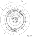
- the Fig. 4 to 10 show how the cover plate 6 is inserted into the base body 4.
- the base body 4 is connected to the cover plate 6 by a relative movement of the first part of the first connecting means 10 with respect to the second part of the first connecting means 10 in the transverse direction 40 such that the cover plate 6 is secured against movement relative to the base body 4 in the direction of the central axis 50.
- This is achieved by pushing the cover plate 6 with its extension 22 in the transverse direction 40 into the opening 21 of the base body 4. No tools are required for this.
- the first connecting means 10 can be installed without tools.
- the first connecting means 10 consists exclusively of the first part on the base body 4 and the second part on the cover plate 6.
- the cover plate 6 has a through-opening 17 in its center. When the cover plate 6 and the base body 4 are connected, the center axis 50 runs through the through-opening 17.
- the cover plate 6 advantageously completely encloses the through-opening 17.
- Fig. 2 In the assembled state of the starter device 2, the driver 81 shown advantageously completely covers the through-opening 17 of the cover plate 6, except for the area of the through-opening 17 in which the hub 73 is arranged. In the connected state of the base body 4 and cover plate 6, the spring receiving space 5 is thus almost completely closed.
- the extension 22 is in the Fig. 10 shown connected state of cover plate 6 and base body 4 in the transverse direction 40 over the spring receiving space 5.
- the extension 22 of the cover plate 6 projects into the opening 21 in the base body 4 when the base body 4 and cover plate 6 are connected.
- the opening 21 has a closed circumferential edge 23.
- the edge 23 of the opening 21 runs around the transverse direction 40.
- the spring housing 1 is designed such that the extension 22 of the cover plate 6 in the opening 21 rests with an upper side 11 of the cover plate on the edge 23 of the opening 21, and that at the same time the cover plate 6 rests outside the opening 21 with an underside 12 of the cover plate 6 on a support surface 8 of the base body 4.
- the cover plate 6 has, in the connected state of the base body 4 and the cover plate 6, both its underside 12 and its upper side 11 in contact with the base body 4. Due to the contact on both sides, the cover plate 6 is fixed in the direction of the central axis 50.
- the upper side 11 of the cover plate 6 is facing away from the floor 9 of the spring receiving space 5 in the connected state of the base body 4 and the cover plate 6.
- the underside 12 of the cover plate 6 is in the connected state of the Base body 4 and the cover plate 6 facing the bottom 9 of the spring receiving space 5 of the base body 4.
- the cover plate 6 has a clamping extension 13.
- the clamping extension 13 of the cover plate 6 protrudes beyond the cover body 7 of the cover plate 6.
- the cover body 7 of the cover plate 6 in the connected state of the base body 4 and cover plate 6 covers the Fig. 9
- the access opening 15 of the spring receiving space 5 shown is at least partially covered.
- the part of the cover plate 6 which, when the base body 4 and the cover plate 6 are connected, protrudes beyond the spring receiving space 5 in the direction of the central axis 50, is not part of the cover body 7.
- the cover body 7 is formed only by the part of the cover plate 6 which, when viewed in the direction of the longitudinal axis 50, does not protrude beyond the spring receiving space 5.
- the clamping extension 13 protrudes in the transverse direction 40 beyond the cover body 7 of the cover plate 6.
- the underside 12 of the cover plate 6 rests on the support surface 8 of the base body 4 when the base body 4 and the cover plate 6 are connected to the clamping extension 13 of the cover plate 6.
- the underside 12 of the extension 22 inserted into the opening 21 rests against the edge 23 of the opening 21.
- the cover plate 6 rests outside the opening 21 with its upper side against a projection or opening in the base body 4.
- the extension 22 inserted through the opening 21 is prestressed in the direction of the central axis 50, i.e. either in the axial direction 49 or counter to the axial direction 49, relative to the part of the cover plate 6 that rests against the base body 4 outside the opening 21. This can be done, for example, as in the Figures 11 and 12 be realized in more detail.
- the extension contact area of the extension contact surface 24 has a smallest distance a to the imaginary plane E.
- the cover plate 6 lies in a clamping contact area on the Figures 12 and 16 shown support surface 8 of the base body 4.
- the clamping contact area of the support surface 8 of the base body 4 has a greatest distance b to the imaginary plane E ( Fig. 16 ).
- the largest distance b of the clamping contact area of the support surface 8 to the imaginary plane E is smaller in the embodiment than the smallest distance a of the extension contact area of the extension contact surface 24 to the imaginary plane E.
- the cover plate 6 has a Figures 16 and 18 The thickness d shown.
- the thickness d of the cover plate 6 is constant in the exemplary embodiment.
- the support surface 8 has a greatest distance d2 to the bottom 9 of the spring receiving space 5, measured in the axial direction 49.
- the support surface 8 has its greatest distance d2 to the bottom 9 at the point of the greatest distance a2 to the central axis 50.
- the support surface 8 has its smallest distance d1 to the bottom 9 at the point of the smallest distance a1 to the central axis 50.
- the distance d1, d2 measured in the axial direction 49 between the base 9 of the spring receiving chamber 5 and the support surface 8 increases in particular with increasing distance a1, a2 from the central axis 50. This increase advantageously occurs continuously. Due to this inclination of the support surface 8, the clamping extension 13 can be easily pushed onto the support surface 8 in the transverse direction 40.
- the clamping extension 13 is raised in the axial direction 49 in comparison to the cover body 7 of the cover plate 6.
- the clamping extension 13 rests with its underside 12 on the support surface 8 of the base body 4.
- the support surface 8 has an axial distance to the imaginary plane E at its greatest distance d2 from the base 9.
- the support surface 8 can also comprise a section in which the surface runs parallel to the plane E.
- the clamping extension 13 of the cover plate 6, in the connected state of the base body 4 and the cover plate 6, lies at least at the transition between the opposite to the imaginary plane E inclined area and the section in which the support surface 8 runs parallel to the plane E, on the support surface 8.
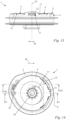
- the Fig. 17 shows a section along the Fig. 14 shown section plane XVII-XVII.
- the section plane XVII-XVII runs in the transverse direction 40 and contains the extension 22.
- the section plane XVII-XVII runs parallel to the section plane XV-XV.
- the section plane XVII-XVII does not contain the central axis 50.
- the extension 22 rests with its upper side 11 on the extension contact surface 24 of the edge 23 of the opening 21 of the base body 4. Due to the Figs. 15 and 16
- the inclined support surface 8 shown which presses the clamping extension 13 upward in the axial direction 49, presses the extension 22 in the axial direction 49 against the extension contact surface 24. Movement of the extension 22 in the axial direction 49 is limited by the extension contact surface 24. This holds the cover body 7 on the base body 4.
- a second extension 25 is provided on the cover plate 6 and a second opening 26 is provided in the base body 4. This is shown, for example, in the Fig. 6 and 10 clearly visible.
- the support surface 8 is arranged between the opening 21 and the second opening 26.
- the upper side 11 of the cover plate 6 rests in the region of the second extension 25 against the second opening 26, as described for the extension 22 with respect to the opening 21.
- the second extension 22 corresponds to the opening 26.
- the cover plate 6 is in the connected state of the base body 4 and cover plate 6, as in Fig.
- the spring receiving space 5 is bounded in the radial direction to the central axis 50 by the peripheral wall 14 of the base body 4.
- the peripheral wall 14 of the spring receiving space 5 runs around the central axis 50.
- the peripheral wall 14 has a smallest distance k from the central axis 50.
- the cover plate 6 is delimited in the direction radially to the central axis 50 by an outer contour 18 of the cover plate 6.
- the outer contour 18 of the cover plate 6 runs around the central axis 50 when the cover plate 6 and the base body 4 are connected.
- a distance a3 of the outer contour 18 of the cover plate 6 from the central axis 50 in a continuous circumferential angular range ⁇ of at least 270° is less than 120% of the smallest distance k.
- the distance a3 of the outer contour 18 of the cover plate 6 from the central axis 50 in a continuous circumferential angular range ⁇ of at least 320° is less than 110% of the smallest distance k.
- no holes for screw passage are provided in the cover plate 6. This allows the cover plate 6 to be designed to be compact in the continuous angular range ⁇ in the radial direction to the central axis 50.
Landscapes
- Engineering & Computer Science (AREA)
- General Engineering & Computer Science (AREA)
- Mechanical Engineering (AREA)
- Chemical & Material Sciences (AREA)
- Combustion & Propulsion (AREA)
- Physics & Mathematics (AREA)
- Acoustics & Sound (AREA)
- Aviation & Aerospace Engineering (AREA)
- Devices For Conveying Motion By Means Of Endless Flexible Members (AREA)
- Springs (AREA)
Claims (14)
- Boîtier de ressort pour un ressort de liaison d'un dispositif de lancement pour démarrer un moteur à combustion interne, le boîtier de ressort (1) comprenant un corps de base (4) avec un espace de réception de ressort (5) et une plaque de recouvrement (6) pour recouvrir au moins partiellement l'espace de réception de ressort (5), la plaque de recouvrement (6) et le corps de base (4) pouvant être reliés entre eux par l'intermédiaire d'au moins un premier moyen de liaison (10), l'au moins un premier moyen de liaison (10) bloquant la plaque de recouvrement (6) contre un mouvement par rapport au corps de base (4) dans la direction d'un axe central (50) du boîtier de ressort (1), caractérisé en ce que l'au moins un premier moyen de liaison (10) est constitué d'une ouverture (21, 26) dans le corps de base (4) et d'un prolongement (22, 25) de la plaque de recouvrement (6) correspondant à l'ouverture (21, 26), en ce que le prolongement (22, 25) peut être enfiché dans l'ouverture (21, 26), en ce que le corps de base (4) peut être relié à la plaque de recouvrement (6) par un mouvement relatif du prolongement (22, 25) du premier moyen de liaison (10) par rapport à l'ouverture (21, 26) du premier moyen de liaison (10) dans une direction transversale (40), transversalement à l'axe central (50), de telle sorte que la plaque de recouvrement (6) est bloquée contre un mouvement par rapport au corps de base (4) dans la direction de l'axe central (50), ce qui est obtenu en poussant la plaque de recouvrement (6) avec son prolongement (22, 25) dans la direction transversale (40) dans l'ouverture (21).
- Boîtier de ressort selon la revendication 1,
caractérisé en ce que l'au moins un premier moyen de liaison (10) peut être monté sans outil. - Boîtier de ressort selon la revendication 1 ou 2,
caractérisé en ce que l'ouverture (21, 26) traverse complètement le corps de base (4) dans la direction transversale (40), transversalement à l'axe central (50). - Boîtier de ressort selon l'une quelconque des revendications 1 à 3,
caractérisé en ce que le prolongement (22, 25), à l'état relié de la plaque de recouvrement (6) et du corps de base (4), fait saillie dans la direction transversale (40) transversalement à l'axe central (50) au-delà de l'espace de réception de ressort (5). - Boîtier de ressort selon l'une quelconque des revendications 1 à 4,
caractérisé en ce qu'il est prévu au moins deux premiers moyens de liaison (10) qui sont agencés dans une plage angulaire périphérique (α) inférieure à 180°, mesurée par rapport à l'axe central (50) à l'état relié de la plaque de recouvrement (6) et du corps de base (4). - Boîtier de ressort selon l'une quelconque des revendications 1 à 5,
caractérisé en ce que l'ouverture (21, 26) possède un bord périphérique fermé (23). - Boîtier de ressort selon l'une quelconque des revendications 1 à 6,
caractérisé en ce que le prolongement (22, 25) enfiché dans l'ouverture (21, 26) est précontraint contre le bord (23) de l'ouverture (21, 26). - Boîtier de ressort selon la revendication 7,
caractérisé en ce que le prolongement (22, 25) de la plaque de recouvrement (6) s'appuie dans l'ouverture (21, 26) avec un côté supérieur (11) de la plaque de recouvrement (6) sur une surface d'appui de prolongement (24) du corps de base (4), et en ce que la plaque de recouvrement (6) s'applique à l'extérieur de l'ouverture (21, 26) avec un côté inférieur (12) de la plaque de recouvrement (6) sur une surface d'application (8) du corps de base (4). - Boîtier de ressort selon la revendication 8,
caractérisé en ce que la surface d'application (8) est inclinée par rapport à un plan imaginaire (E) perpendiculaire à l'axe central (50). - Boîtier de ressort selon l'une quelconque des revendications 1 à 9,
caractérisé en ce que le boîtier de ressort (1) comprend, outre l'au moins un premier moyen de liaison (10), un deuxième moyen de liaison (20) qui bloque la plaque de recouvrement (6) contre un mouvement par rapport au corps de base (4) dans une direction transversale (40) transversalement à l'axe central (50). - Boîtier de ressort selon l'une quelconque des revendications 1 à 10,
caractérisé en ce que le deuxième moyen de liaison (20) comprend une vis (28) qui présente une distance par rapport à l'axe central (50). - Boîtier de ressort selon l'une quelconque des revendications 1 à 11,
caractérisé en ce que le boîtier de ressort (1) est réalisé d'un seul tenant avec une poulie (30) pour un câble de lancement pour lancer le moteur à combustion interne (3). - Boîtier de ressort selon la revendication 12,
caractérisé en ce que la poulie (30) destinée à recevoir le câble de lancement présente une cavité (71) entourant l'axe central (50) avec un fond (76), et en ce que le contour du fond (76) suit une forme circulaire dans une plage angulaire continue (β) d'au moins 270°. - Dispositif de lancement avec un boîtier de ressort (1) selon l'une quelconque des revendications 1 à 13.
Priority Applications (3)
| Application Number | Priority Date | Filing Date | Title |
|---|---|---|---|
| EP19176934.8A EP3744968B1 (fr) | 2019-05-28 | 2019-05-28 | Boîtier de ressort et dispositif de lancement doté d'un tel boîtier de ressort |
| US16/882,613 US11333119B2 (en) | 2019-05-28 | 2020-05-25 | Spring casing and starter device with a spring casing |
| CN202010467370.1A CN112012860B (zh) | 2019-05-28 | 2020-05-28 | 弹簧壳体和带有弹簧壳体的起动装置 |
Applications Claiming Priority (1)
| Application Number | Priority Date | Filing Date | Title |
|---|---|---|---|
| EP19176934.8A EP3744968B1 (fr) | 2019-05-28 | 2019-05-28 | Boîtier de ressort et dispositif de lancement doté d'un tel boîtier de ressort |
Publications (2)
| Publication Number | Publication Date |
|---|---|
| EP3744968A1 EP3744968A1 (fr) | 2020-12-02 |
| EP3744968B1 true EP3744968B1 (fr) | 2025-07-02 |
Family
ID=66857612
Family Applications (1)
| Application Number | Title | Priority Date | Filing Date |
|---|---|---|---|
| EP19176934.8A Active EP3744968B1 (fr) | 2019-05-28 | 2019-05-28 | Boîtier de ressort et dispositif de lancement doté d'un tel boîtier de ressort |
Country Status (3)
| Country | Link |
|---|---|
| US (1) | US11333119B2 (fr) |
| EP (1) | EP3744968B1 (fr) |
| CN (1) | CN112012860B (fr) |
Families Citing this family (2)
| Publication number | Priority date | Publication date | Assignee | Title |
|---|---|---|---|---|
| EP3708822B1 (fr) * | 2019-03-12 | 2025-03-12 | Andreas Stihl AG & Co. KG | Dispositif de lancement, module de poulie pour un dispositif de lancement et ressort de connexion pour un module de poulie |
| SE545241C2 (en) * | 2021-10-14 | 2023-06-07 | Husqvarna Ab | Starter pulley arrangement |
Citations (1)
| Publication number | Priority date | Publication date | Assignee | Title |
|---|---|---|---|---|
| EP1558845B1 (fr) * | 2002-10-08 | 2009-08-05 | MTD Products Inc. | Demarreur a rappel a ressort amortisseur/tampon |
Family Cites Families (22)
| Publication number | Priority date | Publication date | Assignee | Title |
|---|---|---|---|---|
| US3375814A (en) * | 1965-11-26 | 1968-04-02 | Eaton Stamping Co | Pulley construction for recoil starter |
| US3952718A (en) * | 1974-08-12 | 1976-04-27 | Brunswick Corporation | Starter apparatus for internal combustion engines |
| US4019490A (en) * | 1975-05-09 | 1977-04-26 | Tecumseh Products Company | Pull-rope recoil starter |
| US4365690A (en) * | 1978-11-06 | 1982-12-28 | Barnes Group Inc. | Spring cartridge for spring operated re-wind mechanism |
| US4480605A (en) * | 1983-05-09 | 1984-11-06 | Brunswick Corporation | Recoil starter |
| US6230678B1 (en) * | 1998-10-30 | 2001-05-15 | Briggs & Stratton Corporation | Starting and stopping device for internal combustion engine |
| KR100962156B1 (ko) * | 2002-05-20 | 2010-06-10 | 스타팅 고교 가부시키가이샤 | 리코일 시동기 |
| DE10341462B4 (de) * | 2003-09-09 | 2012-11-29 | Andreas Stihl Ag & Co. Kg | Starteinrichtung für einen Verbrennungsmotor |
| JP4376193B2 (ja) * | 2005-02-08 | 2009-12-02 | ハスクバーナ・ゼノア株式会社 | エンジン始動装置とエンジンとの間の動力伝達機構 |
| US7114479B1 (en) * | 2005-09-16 | 2006-10-03 | Hsin-Chih Chung Lee | Cable-pull type engine starting device |
| JP2007171129A (ja) * | 2005-12-26 | 2007-07-05 | Seiko Instruments Inc | 時計 |
| DE102008007291B4 (de) * | 2008-02-02 | 2016-12-22 | Andreas Stihl Ag & Co. Kg | Starteinrichtung für einen Verbrennungsmotor |
| CN201215058Y (zh) | 2008-06-20 | 2009-04-01 | 吴明根 | 小型汽油机易起动装置 |
| DE202008015756U1 (de) | 2008-11-27 | 2010-04-22 | Dolmar Gmbh | Startervorrichtung |
| US8291879B2 (en) * | 2008-12-03 | 2012-10-23 | Techtronic Outdoor Products Technology Limited | Recoil starter system |
| DE202010016015U1 (de) * | 2010-11-30 | 2012-03-01 | Makita Corporation | Startvorrichtung für einen Brennkraftmotor |
| DE202012100536U1 (de) * | 2012-02-17 | 2013-05-27 | Makita Corp. | Startvorrichtung für eine Brennkraftmaschine |
| WO2014137261A1 (fr) * | 2013-03-08 | 2014-09-12 | Husqvarna Ab | Enrouleur à cordon pour appareil de démarrage |
| WO2015072900A1 (fr) | 2013-11-18 | 2015-05-21 | Husqvarna Ab | Dispositif de démarrage pour un moteur à combustion interne |
| WO2015199658A1 (fr) * | 2014-06-24 | 2015-12-30 | Husqvarna Ab | Poulie d'entraînement d'assistance à ressort |
| DE102015001119B4 (de) * | 2015-01-29 | 2024-11-21 | Andreas Stihl Ag & Co. Kg | Starteinrichtung für einen Verbrennungsmotor und handgeführtes Arbeitsgerät mit einem Verbrennungsmotor und mit einer Starteinrichtung |
| CN205552715U (zh) | 2016-04-28 | 2016-09-07 | 浙江合鸿工具有限公司 | 一种用于汽油链锯的启动装置 |
-
2019
- 2019-05-28 EP EP19176934.8A patent/EP3744968B1/fr active Active
-
2020
- 2020-05-25 US US16/882,613 patent/US11333119B2/en active Active
- 2020-05-28 CN CN202010467370.1A patent/CN112012860B/zh active Active
Patent Citations (1)
| Publication number | Priority date | Publication date | Assignee | Title |
|---|---|---|---|---|
| EP1558845B1 (fr) * | 2002-10-08 | 2009-08-05 | MTD Products Inc. | Demarreur a rappel a ressort amortisseur/tampon |
Also Published As
| Publication number | Publication date |
|---|---|
| EP3744968A1 (fr) | 2020-12-02 |
| US20200378351A1 (en) | 2020-12-03 |
| US11333119B2 (en) | 2022-05-17 |
| CN112012860A (zh) | 2020-12-01 |
| CN112012860B (zh) | 2024-05-24 |
Similar Documents
| Publication | Publication Date | Title |
|---|---|---|
| DE102008007291B4 (de) | Starteinrichtung für einen Verbrennungsmotor | |
| EP2198692B1 (fr) | Taille-haie | |
| EP0903071B1 (fr) | Tête de coupe et tondeuse à filament | |
| DE68907285T2 (de) | Halbautomatischer Trimmerkopf. | |
| DE102008023927A1 (de) | Arbeitsgerät | |
| DE3871911T2 (de) | Ketten- oder riemenspanner. | |
| DE102007059135A1 (de) | Handgehaltene Motor-Arbeitsmaschine | |
| DE3831710A1 (de) | Startvorrichtung fuer einen verbrennungsmotor | |
| DE19504432A1 (de) | Stichsäge | |
| EP3282119B1 (fr) | Démarreur à main pour un moteur à combustion interne et outillage dorsal pourvu d'un moteur à combustion interne et d'un démarreur à main pour le moteur à combustion interne | |
| DE102012025321B4 (de) | Vergaser für ein handgeführtes Arbeitsgerät und handgeführtes Arbeitsgerät | |
| DE69316480T2 (de) | Mittel zum Zuführen des Fadens für Schneidkopf | |
| DE4208715C2 (de) | Schrauber | |
| EP3925427A1 (fr) | Tête de coupe pour une débroussailleuse | |
| DE102007008327B4 (de) | Starteinrichtung für einen Verbrennungsmotor | |
| EP3744968B1 (fr) | Boîtier de ressort et dispositif de lancement doté d'un tel boîtier de ressort | |
| EP3785518B1 (fr) | Tête de faucheuse à monter sur un arbre d'entraînement d'une débroussailleuse | |
| WO2016045773A1 (fr) | Appareil de travail | |
| EP0037021A1 (fr) | Dispositif de fixation d'un rotatif outil dentaire | |
| DE3218569C2 (fr) | ||
| EP3540208B1 (fr) | Démarreur à main permettant de démarrer un moteur à combustion interne et appareil de travail guidé à la main doté d'un démarreur à main | |
| DE102015001119B4 (de) | Starteinrichtung für einen Verbrennungsmotor und handgeführtes Arbeitsgerät mit einem Verbrennungsmotor und mit einer Starteinrichtung | |
| DE3608941A1 (de) | Gashebel-schaltvorrichtung fuer motorisch angetriebene, handgefuehrte arbeitsgeraete, insbesondere motorkettensaegen | |
| DE4128316A1 (de) | Einhebelbetaetigungsvorrichtung | |
| DE3516644A1 (de) | Permutationsschloss fuer koffer oder dergleichen |
Legal Events
| Date | Code | Title | Description |
|---|---|---|---|
| PUAI | Public reference made under article 153(3) epc to a published international application that has entered the european phase |
Free format text: ORIGINAL CODE: 0009012 |
|
| STAA | Information on the status of an ep patent application or granted ep patent |
Free format text: STATUS: THE APPLICATION HAS BEEN PUBLISHED |
|
| AK | Designated contracting states |
Kind code of ref document: A1 Designated state(s): AL AT BE BG CH CY CZ DE DK EE ES FI FR GB GR HR HU IE IS IT LI LT LU LV MC MK MT NL NO PL PT RO RS SE SI SK SM TR |
|
| AX | Request for extension of the european patent |
Extension state: BA ME |
|
| STAA | Information on the status of an ep patent application or granted ep patent |
Free format text: STATUS: REQUEST FOR EXAMINATION WAS MADE |
|
| 17P | Request for examination filed |
Effective date: 20210601 |
|
| RBV | Designated contracting states (corrected) |
Designated state(s): AL AT BE BG CH CY CZ DE DK EE ES FI FR GB GR HR HU IE IS IT LI LT LU LV MC MK MT NL NO PL PT RO RS SE SI SK SM TR |
|
| STAA | Information on the status of an ep patent application or granted ep patent |
Free format text: STATUS: EXAMINATION IS IN PROGRESS |
|
| 17Q | First examination report despatched |
Effective date: 20230313 |
|
| RIC1 | Information provided on ipc code assigned before grant |
Ipc: F16F 1/12 20060101ALI20241218BHEP Ipc: B65H 75/42 20060101ALI20241218BHEP Ipc: B65H 75/44 20060101ALI20241218BHEP Ipc: F16F 1/10 20060101ALI20241218BHEP Ipc: F02N 15/00 20060101ALI20241218BHEP Ipc: F02N 3/02 20060101AFI20241218BHEP |
|
| GRAP | Despatch of communication of intention to grant a patent |
Free format text: ORIGINAL CODE: EPIDOSNIGR1 |
|
| STAA | Information on the status of an ep patent application or granted ep patent |
Free format text: STATUS: GRANT OF PATENT IS INTENDED |
|
| INTG | Intention to grant announced |
Effective date: 20250128 |
|
| GRAS | Grant fee paid |
Free format text: ORIGINAL CODE: EPIDOSNIGR3 |
|
| GRAA | (expected) grant |
Free format text: ORIGINAL CODE: 0009210 |
|
| STAA | Information on the status of an ep patent application or granted ep patent |
Free format text: STATUS: THE PATENT HAS BEEN GRANTED |
|
| AK | Designated contracting states |
Kind code of ref document: B1 Designated state(s): AL AT BE BG CH CY CZ DE DK EE ES FI FR GB GR HR HU IE IS IT LI LT LU LV MC MK MT NL NO PL PT RO RS SE SI SK SM TR |
|
| REG | Reference to a national code |
Ref country code: GB Ref legal event code: FG4D Free format text: NOT ENGLISH |
|
| REG | Reference to a national code |
Ref country code: CH Ref legal event code: EP |
|
| REG | Reference to a national code |
Ref country code: DE Ref legal event code: R096 Ref document number: 502019013539 Country of ref document: DE |
|
| REG | Reference to a national code |
Ref country code: IE Ref legal event code: FG4D Free format text: LANGUAGE OF EP DOCUMENT: GERMAN |
|
| REG | Reference to a national code |
Ref country code: NL Ref legal event code: MP Effective date: 20250702 |
|
| PG25 | Lapsed in a contracting state [announced via postgrant information from national office to epo] |
Ref country code: PT Free format text: LAPSE BECAUSE OF FAILURE TO SUBMIT A TRANSLATION OF THE DESCRIPTION OR TO PAY THE FEE WITHIN THE PRESCRIBED TIME-LIMIT Effective date: 20251103 |
|
| PG25 | Lapsed in a contracting state [announced via postgrant information from national office to epo] |
Ref country code: NL Free format text: LAPSE BECAUSE OF FAILURE TO SUBMIT A TRANSLATION OF THE DESCRIPTION OR TO PAY THE FEE WITHIN THE PRESCRIBED TIME-LIMIT Effective date: 20250702 |
|
| PG25 | Lapsed in a contracting state [announced via postgrant information from national office to epo] |
Ref country code: IS Free format text: LAPSE BECAUSE OF FAILURE TO SUBMIT A TRANSLATION OF THE DESCRIPTION OR TO PAY THE FEE WITHIN THE PRESCRIBED TIME-LIMIT Effective date: 20251102 |
|
| PG25 | Lapsed in a contracting state [announced via postgrant information from national office to epo] |
Ref country code: NO Free format text: LAPSE BECAUSE OF FAILURE TO SUBMIT A TRANSLATION OF THE DESCRIPTION OR TO PAY THE FEE WITHIN THE PRESCRIBED TIME-LIMIT Effective date: 20251002 |
|
| REG | Reference to a national code |
Ref country code: LT Ref legal event code: MG9D |
|
| PG25 | Lapsed in a contracting state [announced via postgrant information from national office to epo] |
Ref country code: FI Free format text: LAPSE BECAUSE OF FAILURE TO SUBMIT A TRANSLATION OF THE DESCRIPTION OR TO PAY THE FEE WITHIN THE PRESCRIBED TIME-LIMIT Effective date: 20250702 |
|
| PG25 | Lapsed in a contracting state [announced via postgrant information from national office to epo] |
Ref country code: HR Free format text: LAPSE BECAUSE OF FAILURE TO SUBMIT A TRANSLATION OF THE DESCRIPTION OR TO PAY THE FEE WITHIN THE PRESCRIBED TIME-LIMIT Effective date: 20250702 |
|
| PG25 | Lapsed in a contracting state [announced via postgrant information from national office to epo] |
Ref country code: GR Free format text: LAPSE BECAUSE OF FAILURE TO SUBMIT A TRANSLATION OF THE DESCRIPTION OR TO PAY THE FEE WITHIN THE PRESCRIBED TIME-LIMIT Effective date: 20251003 |
|
| PG25 | Lapsed in a contracting state [announced via postgrant information from national office to epo] |
Ref country code: SE Free format text: LAPSE BECAUSE OF FAILURE TO SUBMIT A TRANSLATION OF THE DESCRIPTION OR TO PAY THE FEE WITHIN THE PRESCRIBED TIME-LIMIT Effective date: 20250702 Ref country code: CZ Free format text: LAPSE BECAUSE OF FAILURE TO SUBMIT A TRANSLATION OF THE DESCRIPTION OR TO PAY THE FEE WITHIN THE PRESCRIBED TIME-LIMIT Effective date: 20250702 |
|
| PG25 | Lapsed in a contracting state [announced via postgrant information from national office to epo] |
Ref country code: LV Free format text: LAPSE BECAUSE OF FAILURE TO SUBMIT A TRANSLATION OF THE DESCRIPTION OR TO PAY THE FEE WITHIN THE PRESCRIBED TIME-LIMIT Effective date: 20250702 |
|
| PG25 | Lapsed in a contracting state [announced via postgrant information from national office to epo] |
Ref country code: BG Free format text: LAPSE BECAUSE OF FAILURE TO SUBMIT A TRANSLATION OF THE DESCRIPTION OR TO PAY THE FEE WITHIN THE PRESCRIBED TIME-LIMIT Effective date: 20250702 Ref country code: PL Free format text: LAPSE BECAUSE OF FAILURE TO SUBMIT A TRANSLATION OF THE DESCRIPTION OR TO PAY THE FEE WITHIN THE PRESCRIBED TIME-LIMIT Effective date: 20250702 |
|
| PG25 | Lapsed in a contracting state [announced via postgrant information from national office to epo] |
Ref country code: RS Free format text: LAPSE BECAUSE OF FAILURE TO SUBMIT A TRANSLATION OF THE DESCRIPTION OR TO PAY THE FEE WITHIN THE PRESCRIBED TIME-LIMIT Effective date: 20251002 |
|
| PG25 | Lapsed in a contracting state [announced via postgrant information from national office to epo] |
Ref country code: ES Free format text: LAPSE BECAUSE OF FAILURE TO SUBMIT A TRANSLATION OF THE DESCRIPTION OR TO PAY THE FEE WITHIN THE PRESCRIBED TIME-LIMIT Effective date: 20250702 |
|
| PG25 | Lapsed in a contracting state [announced via postgrant information from national office to epo] |
Ref country code: SM Free format text: LAPSE BECAUSE OF FAILURE TO SUBMIT A TRANSLATION OF THE DESCRIPTION OR TO PAY THE FEE WITHIN THE PRESCRIBED TIME-LIMIT Effective date: 20250702 |
|
| PG25 | Lapsed in a contracting state [announced via postgrant information from national office to epo] |
Ref country code: DK Free format text: LAPSE BECAUSE OF FAILURE TO SUBMIT A TRANSLATION OF THE DESCRIPTION OR TO PAY THE FEE WITHIN THE PRESCRIBED TIME-LIMIT Effective date: 20250702 |
|
| PG25 | Lapsed in a contracting state [announced via postgrant information from national office to epo] |
Ref country code: IT Free format text: LAPSE BECAUSE OF FAILURE TO SUBMIT A TRANSLATION OF THE DESCRIPTION OR TO PAY THE FEE WITHIN THE PRESCRIBED TIME-LIMIT Effective date: 20250702 |
|
| PG25 | Lapsed in a contracting state [announced via postgrant information from national office to epo] |
Ref country code: SK Free format text: LAPSE BECAUSE OF FAILURE TO SUBMIT A TRANSLATION OF THE DESCRIPTION OR TO PAY THE FEE WITHIN THE PRESCRIBED TIME-LIMIT Effective date: 20250702 Ref country code: EE Free format text: LAPSE BECAUSE OF FAILURE TO SUBMIT A TRANSLATION OF THE DESCRIPTION OR TO PAY THE FEE WITHIN THE PRESCRIBED TIME-LIMIT Effective date: 20250702 |