EP3744988B1 - Dispositif d'entraînement hydraulique pour engin de chantier - Google Patents
Dispositif d'entraînement hydraulique pour engin de chantier Download PDFInfo
- Publication number
- EP3744988B1 EP3744988B1 EP19845986.9A EP19845986A EP3744988B1 EP 3744988 B1 EP3744988 B1 EP 3744988B1 EP 19845986 A EP19845986 A EP 19845986A EP 3744988 B1 EP3744988 B1 EP 3744988B1
- Authority
- EP
- European Patent Office
- Prior art keywords
- valve
- valves
- controller
- directional switching
- actuator
- Prior art date
- Legal status (The legal status is an assumption and is not a legal conclusion. Google has not performed a legal analysis and makes no representation as to the accuracy of the status listed.)
- Active
Links
Images






Classifications
-
- E—FIXED CONSTRUCTIONS
- E02—HYDRAULIC ENGINEERING; FOUNDATIONS; SOIL SHIFTING
- E02F—DREDGING; SOIL-SHIFTING
- E02F9/00—Component parts of dredgers or soil-shifting machines, not restricted to one of the kinds covered by groups E02F3/00 - E02F7/00
- E02F9/20—Drives; Control devices
- E02F9/22—Hydraulic or pneumatic drives
- E02F9/2278—Hydraulic circuits
- E02F9/2289—Closed circuit
-
- E—FIXED CONSTRUCTIONS
- E02—HYDRAULIC ENGINEERING; FOUNDATIONS; SOIL SHIFTING
- E02F—DREDGING; SOIL-SHIFTING
- E02F9/00—Component parts of dredgers or soil-shifting machines, not restricted to one of the kinds covered by groups E02F3/00 - E02F7/00
- E02F9/20—Drives; Control devices
- E02F9/22—Hydraulic or pneumatic drives
- E02F9/2278—Hydraulic circuits
- E02F9/2292—Systems with two or more pumps
-
- E—FIXED CONSTRUCTIONS
- E02—HYDRAULIC ENGINEERING; FOUNDATIONS; SOIL SHIFTING
- E02F—DREDGING; SOIL-SHIFTING
- E02F9/00—Component parts of dredgers or soil-shifting machines, not restricted to one of the kinds covered by groups E02F3/00 - E02F7/00
- E02F9/20—Drives; Control devices
- E02F9/22—Hydraulic or pneumatic drives
- E02F9/2264—Arrangements or adaptations of elements for hydraulic drives
- E02F9/2267—Valves or distributors
-
- E—FIXED CONSTRUCTIONS
- E02—HYDRAULIC ENGINEERING; FOUNDATIONS; SOIL SHIFTING
- E02F—DREDGING; SOIL-SHIFTING
- E02F9/00—Component parts of dredgers or soil-shifting machines, not restricted to one of the kinds covered by groups E02F3/00 - E02F7/00
- E02F9/20—Drives; Control devices
- E02F9/22—Hydraulic or pneumatic drives
- E02F9/2278—Hydraulic circuits
- E02F9/2296—Systems with a variable displacement pump
-
- E—FIXED CONSTRUCTIONS
- E02—HYDRAULIC ENGINEERING; FOUNDATIONS; SOIL SHIFTING
- E02F—DREDGING; SOIL-SHIFTING
- E02F9/00—Component parts of dredgers or soil-shifting machines, not restricted to one of the kinds covered by groups E02F3/00 - E02F7/00
- E02F9/26—Indicating devices
- E02F9/267—Diagnosing or detecting failure of vehicles
-
- F—MECHANICAL ENGINEERING; LIGHTING; HEATING; WEAPONS; BLASTING
- F15—FLUID-PRESSURE ACTUATORS; HYDRAULICS OR PNEUMATICS IN GENERAL
- F15B—SYSTEMS ACTING BY MEANS OF FLUIDS IN GENERAL; FLUID-PRESSURE ACTUATORS, e.g. SERVOMOTORS; DETAILS OF FLUID-PRESSURE SYSTEMS, NOT OTHERWISE PROVIDED FOR
- F15B11/00—Servomotor systems without provision for follow-up action; Circuits therefor
- F15B11/16—Servomotor systems without provision for follow-up action; Circuits therefor with two or more servomotors
- F15B11/17—Servomotor systems without provision for follow-up action; Circuits therefor with two or more servomotors using two or more pumps
-
- F—MECHANICAL ENGINEERING; LIGHTING; HEATING; WEAPONS; BLASTING
- F15—FLUID-PRESSURE ACTUATORS; HYDRAULICS OR PNEUMATICS IN GENERAL
- F15B—SYSTEMS ACTING BY MEANS OF FLUIDS IN GENERAL; FLUID-PRESSURE ACTUATORS, e.g. SERVOMOTORS; DETAILS OF FLUID-PRESSURE SYSTEMS, NOT OTHERWISE PROVIDED FOR
- F15B19/00—Testing; Calibrating; Fault detection or monitoring; Simulation or modelling of fluid-pressure systems or apparatus not otherwise provided for
- F15B19/005—Fault detection or monitoring
-
- F—MECHANICAL ENGINEERING; LIGHTING; HEATING; WEAPONS; BLASTING
- F15—FLUID-PRESSURE ACTUATORS; HYDRAULICS OR PNEUMATICS IN GENERAL
- F15B—SYSTEMS ACTING BY MEANS OF FLUIDS IN GENERAL; FLUID-PRESSURE ACTUATORS, e.g. SERVOMOTORS; DETAILS OF FLUID-PRESSURE SYSTEMS, NOT OTHERWISE PROVIDED FOR
- F15B20/00—Safety arrangements for fluid actuator systems; Applications of safety devices in fluid actuator systems; Emergency measures for fluid actuator systems
- F15B20/008—Valve failure
-
- F—MECHANICAL ENGINEERING; LIGHTING; HEATING; WEAPONS; BLASTING
- F15—FLUID-PRESSURE ACTUATORS; HYDRAULICS OR PNEUMATICS IN GENERAL
- F15B—SYSTEMS ACTING BY MEANS OF FLUIDS IN GENERAL; FLUID-PRESSURE ACTUATORS, e.g. SERVOMOTORS; DETAILS OF FLUID-PRESSURE SYSTEMS, NOT OTHERWISE PROVIDED FOR
- F15B21/00—Common features of fluid actuator systems; Fluid-pressure actuator systems or details thereof, not covered by any other group of this subclass
- F15B21/08—Servomotor systems incorporating electrically operated control means
- F15B21/087—Control strategy, e.g. with block diagram
-
- F—MECHANICAL ENGINEERING; LIGHTING; HEATING; WEAPONS; BLASTING
- F15—FLUID-PRESSURE ACTUATORS; HYDRAULICS OR PNEUMATICS IN GENERAL
- F15B—SYSTEMS ACTING BY MEANS OF FLUIDS IN GENERAL; FLUID-PRESSURE ACTUATORS, e.g. SERVOMOTORS; DETAILS OF FLUID-PRESSURE SYSTEMS, NOT OTHERWISE PROVIDED FOR
- F15B7/00—Systems in which the movement produced is definitely related to the output of a volumetric pump; Telemotors
- F15B7/003—Systems in which the movement produced is definitely related to the output of a volumetric pump; Telemotors with multiple outputs
-
- F—MECHANICAL ENGINEERING; LIGHTING; HEATING; WEAPONS; BLASTING
- F15—FLUID-PRESSURE ACTUATORS; HYDRAULICS OR PNEUMATICS IN GENERAL
- F15B—SYSTEMS ACTING BY MEANS OF FLUIDS IN GENERAL; FLUID-PRESSURE ACTUATORS, e.g. SERVOMOTORS; DETAILS OF FLUID-PRESSURE SYSTEMS, NOT OTHERWISE PROVIDED FOR
- F15B7/00—Systems in which the movement produced is definitely related to the output of a volumetric pump; Telemotors
- F15B7/005—With rotary or crank input
- F15B7/006—Rotary pump input
-
- E—FIXED CONSTRUCTIONS
- E02—HYDRAULIC ENGINEERING; FOUNDATIONS; SOIL SHIFTING
- E02F—DREDGING; SOIL-SHIFTING
- E02F9/00—Component parts of dredgers or soil-shifting machines, not restricted to one of the kinds covered by groups E02F3/00 - E02F7/00
- E02F9/20—Drives; Control devices
- E02F9/22—Hydraulic or pneumatic drives
- E02F9/2221—Control of flow rate; Load sensing arrangements
- E02F9/2225—Control of flow rate; Load sensing arrangements using pressure-compensating valves
- E02F9/2228—Control of flow rate; Load sensing arrangements using pressure-compensating valves including an electronic controller
-
- F—MECHANICAL ENGINEERING; LIGHTING; HEATING; WEAPONS; BLASTING
- F15—FLUID-PRESSURE ACTUATORS; HYDRAULICS OR PNEUMATICS IN GENERAL
- F15B—SYSTEMS ACTING BY MEANS OF FLUIDS IN GENERAL; FLUID-PRESSURE ACTUATORS, e.g. SERVOMOTORS; DETAILS OF FLUID-PRESSURE SYSTEMS, NOT OTHERWISE PROVIDED FOR
- F15B2211/00—Circuits for servomotor systems
- F15B2211/20—Fluid pressure source, e.g. accumulator or variable axial piston pump
- F15B2211/205—Systems with pumps
- F15B2211/2053—Type of pump
- F15B2211/20546—Type of pump variable capacity
-
- F—MECHANICAL ENGINEERING; LIGHTING; HEATING; WEAPONS; BLASTING
- F15—FLUID-PRESSURE ACTUATORS; HYDRAULICS OR PNEUMATICS IN GENERAL
- F15B—SYSTEMS ACTING BY MEANS OF FLUIDS IN GENERAL; FLUID-PRESSURE ACTUATORS, e.g. SERVOMOTORS; DETAILS OF FLUID-PRESSURE SYSTEMS, NOT OTHERWISE PROVIDED FOR
- F15B2211/00—Circuits for servomotor systems
- F15B2211/20—Fluid pressure source, e.g. accumulator or variable axial piston pump
- F15B2211/205—Systems with pumps
- F15B2211/2053—Type of pump
- F15B2211/20561—Type of pump reversible
-
- F—MECHANICAL ENGINEERING; LIGHTING; HEATING; WEAPONS; BLASTING
- F15—FLUID-PRESSURE ACTUATORS; HYDRAULICS OR PNEUMATICS IN GENERAL
- F15B—SYSTEMS ACTING BY MEANS OF FLUIDS IN GENERAL; FLUID-PRESSURE ACTUATORS, e.g. SERVOMOTORS; DETAILS OF FLUID-PRESSURE SYSTEMS, NOT OTHERWISE PROVIDED FOR
- F15B2211/00—Circuits for servomotor systems
- F15B2211/20—Fluid pressure source, e.g. accumulator or variable axial piston pump
- F15B2211/205—Systems with pumps
- F15B2211/20576—Systems with pumps with multiple pumps
-
- F—MECHANICAL ENGINEERING; LIGHTING; HEATING; WEAPONS; BLASTING
- F15—FLUID-PRESSURE ACTUATORS; HYDRAULICS OR PNEUMATICS IN GENERAL
- F15B—SYSTEMS ACTING BY MEANS OF FLUIDS IN GENERAL; FLUID-PRESSURE ACTUATORS, e.g. SERVOMOTORS; DETAILS OF FLUID-PRESSURE SYSTEMS, NOT OTHERWISE PROVIDED FOR
- F15B2211/00—Circuits for servomotor systems
- F15B2211/20—Fluid pressure source, e.g. accumulator or variable axial piston pump
- F15B2211/27—Directional control by means of the pressure source
-
- F—MECHANICAL ENGINEERING; LIGHTING; HEATING; WEAPONS; BLASTING
- F15—FLUID-PRESSURE ACTUATORS; HYDRAULICS OR PNEUMATICS IN GENERAL
- F15B—SYSTEMS ACTING BY MEANS OF FLUIDS IN GENERAL; FLUID-PRESSURE ACTUATORS, e.g. SERVOMOTORS; DETAILS OF FLUID-PRESSURE SYSTEMS, NOT OTHERWISE PROVIDED FOR
- F15B2211/00—Circuits for servomotor systems
- F15B2211/30—Directional control
- F15B2211/305—Directional control characterised by the type of valves
- F15B2211/3056—Assemblies of multiple valves
- F15B2211/30565—Assemblies of multiple valves having multiple valves for a single output member, e.g. for creating higher valve function by use of multiple valves like two 2/2-valves replacing a 5/3-valve
-
- F—MECHANICAL ENGINEERING; LIGHTING; HEATING; WEAPONS; BLASTING
- F15—FLUID-PRESSURE ACTUATORS; HYDRAULICS OR PNEUMATICS IN GENERAL
- F15B—SYSTEMS ACTING BY MEANS OF FLUIDS IN GENERAL; FLUID-PRESSURE ACTUATORS, e.g. SERVOMOTORS; DETAILS OF FLUID-PRESSURE SYSTEMS, NOT OTHERWISE PROVIDED FOR
- F15B2211/00—Circuits for servomotor systems
- F15B2211/30—Directional control
- F15B2211/305—Directional control characterised by the type of valves
- F15B2211/3056—Assemblies of multiple valves
- F15B2211/3059—Assemblies of multiple valves having multiple valves for multiple output members
- F15B2211/30595—Assemblies of multiple valves having multiple valves for multiple output members with additional valves between the groups of valves for multiple output members
-
- F—MECHANICAL ENGINEERING; LIGHTING; HEATING; WEAPONS; BLASTING
- F15—FLUID-PRESSURE ACTUATORS; HYDRAULICS OR PNEUMATICS IN GENERAL
- F15B—SYSTEMS ACTING BY MEANS OF FLUIDS IN GENERAL; FLUID-PRESSURE ACTUATORS, e.g. SERVOMOTORS; DETAILS OF FLUID-PRESSURE SYSTEMS, NOT OTHERWISE PROVIDED FOR
- F15B2211/00—Circuits for servomotor systems
- F15B2211/30—Directional control
- F15B2211/315—Directional control characterised by the connections of the valve or valves in the circuit
- F15B2211/31523—Directional control characterised by the connections of the valve or valves in the circuit being connected to a pressure source and an output member
- F15B2211/31547—Directional control characterised by the connections of the valve or valves in the circuit being connected to a pressure source and an output member having multiple pressure sources and multiple output members
-
- F—MECHANICAL ENGINEERING; LIGHTING; HEATING; WEAPONS; BLASTING
- F15—FLUID-PRESSURE ACTUATORS; HYDRAULICS OR PNEUMATICS IN GENERAL
- F15B—SYSTEMS ACTING BY MEANS OF FLUIDS IN GENERAL; FLUID-PRESSURE ACTUATORS, e.g. SERVOMOTORS; DETAILS OF FLUID-PRESSURE SYSTEMS, NOT OTHERWISE PROVIDED FOR
- F15B2211/00—Circuits for servomotor systems
- F15B2211/30—Directional control
- F15B2211/32—Directional control characterised by the type of actuation
- F15B2211/327—Directional control characterised by the type of actuation electrically or electronically
-
- F—MECHANICAL ENGINEERING; LIGHTING; HEATING; WEAPONS; BLASTING
- F15—FLUID-PRESSURE ACTUATORS; HYDRAULICS OR PNEUMATICS IN GENERAL
- F15B—SYSTEMS ACTING BY MEANS OF FLUIDS IN GENERAL; FLUID-PRESSURE ACTUATORS, e.g. SERVOMOTORS; DETAILS OF FLUID-PRESSURE SYSTEMS, NOT OTHERWISE PROVIDED FOR
- F15B2211/00—Circuits for servomotor systems
- F15B2211/40—Flow control
- F15B2211/405—Flow control characterised by the type of flow control means or valve
- F15B2211/40576—Assemblies of multiple valves
- F15B2211/40592—Assemblies of multiple valves with multiple valves in parallel flow paths
-
- F—MECHANICAL ENGINEERING; LIGHTING; HEATING; WEAPONS; BLASTING
- F15—FLUID-PRESSURE ACTUATORS; HYDRAULICS OR PNEUMATICS IN GENERAL
- F15B—SYSTEMS ACTING BY MEANS OF FLUIDS IN GENERAL; FLUID-PRESSURE ACTUATORS, e.g. SERVOMOTORS; DETAILS OF FLUID-PRESSURE SYSTEMS, NOT OTHERWISE PROVIDED FOR
- F15B2211/00—Circuits for servomotor systems
- F15B2211/60—Circuit components or control therefor
- F15B2211/63—Electronic controllers
- F15B2211/6303—Electronic controllers using input signals
- F15B2211/6306—Electronic controllers using input signals representing a pressure
- F15B2211/6309—Electronic controllers using input signals representing a pressure the pressure being a pressure source supply pressure
-
- F—MECHANICAL ENGINEERING; LIGHTING; HEATING; WEAPONS; BLASTING
- F15—FLUID-PRESSURE ACTUATORS; HYDRAULICS OR PNEUMATICS IN GENERAL
- F15B—SYSTEMS ACTING BY MEANS OF FLUIDS IN GENERAL; FLUID-PRESSURE ACTUATORS, e.g. SERVOMOTORS; DETAILS OF FLUID-PRESSURE SYSTEMS, NOT OTHERWISE PROVIDED FOR
- F15B2211/00—Circuits for servomotor systems
- F15B2211/60—Circuit components or control therefor
- F15B2211/63—Electronic controllers
- F15B2211/6303—Electronic controllers using input signals
- F15B2211/6306—Electronic controllers using input signals representing a pressure
- F15B2211/6313—Electronic controllers using input signals representing a pressure the pressure being a load pressure
-
- F—MECHANICAL ENGINEERING; LIGHTING; HEATING; WEAPONS; BLASTING
- F15—FLUID-PRESSURE ACTUATORS; HYDRAULICS OR PNEUMATICS IN GENERAL
- F15B—SYSTEMS ACTING BY MEANS OF FLUIDS IN GENERAL; FLUID-PRESSURE ACTUATORS, e.g. SERVOMOTORS; DETAILS OF FLUID-PRESSURE SYSTEMS, NOT OTHERWISE PROVIDED FOR
- F15B2211/00—Circuits for servomotor systems
- F15B2211/60—Circuit components or control therefor
- F15B2211/63—Electronic controllers
- F15B2211/6303—Electronic controllers using input signals
- F15B2211/634—Electronic controllers using input signals representing a state of a valve
-
- F—MECHANICAL ENGINEERING; LIGHTING; HEATING; WEAPONS; BLASTING
- F15—FLUID-PRESSURE ACTUATORS; HYDRAULICS OR PNEUMATICS IN GENERAL
- F15B—SYSTEMS ACTING BY MEANS OF FLUIDS IN GENERAL; FLUID-PRESSURE ACTUATORS, e.g. SERVOMOTORS; DETAILS OF FLUID-PRESSURE SYSTEMS, NOT OTHERWISE PROVIDED FOR
- F15B2211/00—Circuits for servomotor systems
- F15B2211/60—Circuit components or control therefor
- F15B2211/63—Electronic controllers
- F15B2211/6303—Electronic controllers using input signals
- F15B2211/6346—Electronic controllers using input signals representing a state of input means, e.g. joystick position
-
- F—MECHANICAL ENGINEERING; LIGHTING; HEATING; WEAPONS; BLASTING
- F15—FLUID-PRESSURE ACTUATORS; HYDRAULICS OR PNEUMATICS IN GENERAL
- F15B—SYSTEMS ACTING BY MEANS OF FLUIDS IN GENERAL; FLUID-PRESSURE ACTUATORS, e.g. SERVOMOTORS; DETAILS OF FLUID-PRESSURE SYSTEMS, NOT OTHERWISE PROVIDED FOR
- F15B2211/00—Circuits for servomotor systems
- F15B2211/70—Output members, e.g. hydraulic motors or cylinders or control therefor
- F15B2211/705—Output members, e.g. hydraulic motors or cylinders or control therefor characterised by the type of output members or actuators
- F15B2211/7051—Linear output members
- F15B2211/7053—Double-acting output members
-
- F—MECHANICAL ENGINEERING; LIGHTING; HEATING; WEAPONS; BLASTING
- F15—FLUID-PRESSURE ACTUATORS; HYDRAULICS OR PNEUMATICS IN GENERAL
- F15B—SYSTEMS ACTING BY MEANS OF FLUIDS IN GENERAL; FLUID-PRESSURE ACTUATORS, e.g. SERVOMOTORS; DETAILS OF FLUID-PRESSURE SYSTEMS, NOT OTHERWISE PROVIDED FOR
- F15B2211/00—Circuits for servomotor systems
- F15B2211/70—Output members, e.g. hydraulic motors or cylinders or control therefor
- F15B2211/71—Multiple output members, e.g. multiple hydraulic motors or cylinders
- F15B2211/7142—Multiple output members, e.g. multiple hydraulic motors or cylinders the output members being arranged in multiple groups
-
- F—MECHANICAL ENGINEERING; LIGHTING; HEATING; WEAPONS; BLASTING
- F15—FLUID-PRESSURE ACTUATORS; HYDRAULICS OR PNEUMATICS IN GENERAL
- F15B—SYSTEMS ACTING BY MEANS OF FLUIDS IN GENERAL; FLUID-PRESSURE ACTUATORS, e.g. SERVOMOTORS; DETAILS OF FLUID-PRESSURE SYSTEMS, NOT OTHERWISE PROVIDED FOR
- F15B2211/00—Circuits for servomotor systems
- F15B2211/70—Output members, e.g. hydraulic motors or cylinders or control therefor
- F15B2211/785—Compensation of the difference in flow rate in closed fluid circuits using differential actuators
-
- F—MECHANICAL ENGINEERING; LIGHTING; HEATING; WEAPONS; BLASTING
- F15—FLUID-PRESSURE ACTUATORS; HYDRAULICS OR PNEUMATICS IN GENERAL
- F15B—SYSTEMS ACTING BY MEANS OF FLUIDS IN GENERAL; FLUID-PRESSURE ACTUATORS, e.g. SERVOMOTORS; DETAILS OF FLUID-PRESSURE SYSTEMS, NOT OTHERWISE PROVIDED FOR
- F15B2211/00—Circuits for servomotor systems
- F15B2211/80—Other types of control related to particular problems or conditions
- F15B2211/857—Monitoring of fluid pressure systems
-
- F—MECHANICAL ENGINEERING; LIGHTING; HEATING; WEAPONS; BLASTING
- F15—FLUID-PRESSURE ACTUATORS; HYDRAULICS OR PNEUMATICS IN GENERAL
- F15B—SYSTEMS ACTING BY MEANS OF FLUIDS IN GENERAL; FLUID-PRESSURE ACTUATORS, e.g. SERVOMOTORS; DETAILS OF FLUID-PRESSURE SYSTEMS, NOT OTHERWISE PROVIDED FOR
- F15B2211/00—Circuits for servomotor systems
- F15B2211/80—Other types of control related to particular problems or conditions
- F15B2211/86—Control during or prevention of abnormal conditions
- F15B2211/863—Control during or prevention of abnormal conditions the abnormal condition being a hydraulic or pneumatic failure
- F15B2211/8636—Circuit failure, e.g. valve or hose failure
-
- F—MECHANICAL ENGINEERING; LIGHTING; HEATING; WEAPONS; BLASTING
- F15—FLUID-PRESSURE ACTUATORS; HYDRAULICS OR PNEUMATICS IN GENERAL
- F15B—SYSTEMS ACTING BY MEANS OF FLUIDS IN GENERAL; FLUID-PRESSURE ACTUATORS, e.g. SERVOMOTORS; DETAILS OF FLUID-PRESSURE SYSTEMS, NOT OTHERWISE PROVIDED FOR
- F15B2211/00—Circuits for servomotor systems
- F15B2211/80—Other types of control related to particular problems or conditions
- F15B2211/865—Prevention of failures
-
- F—MECHANICAL ENGINEERING; LIGHTING; HEATING; WEAPONS; BLASTING
- F15—FLUID-PRESSURE ACTUATORS; HYDRAULICS OR PNEUMATICS IN GENERAL
- F15B—SYSTEMS ACTING BY MEANS OF FLUIDS IN GENERAL; FLUID-PRESSURE ACTUATORS, e.g. SERVOMOTORS; DETAILS OF FLUID-PRESSURE SYSTEMS, NOT OTHERWISE PROVIDED FOR
- F15B2211/00—Circuits for servomotor systems
- F15B2211/80—Other types of control related to particular problems or conditions
- F15B2211/875—Control measures for coping with failures
- F15B2211/8757—Control measures for coping with failures using redundant components or assemblies
Definitions
- an aspect of the present invention is a hydraulic drive device for a working machine, including a hydraulic pump; an actuator driven by pressure oil from the hydraulic pump; a first on-off valve opening/closing a flow passage between the hydraulic pump and the actuator, a second on-off valve arranged in parallel with the first on-off valve and opening/closing a flow passage between the hydraulic pump and the actuator; a first directional switching valve capable of switching between a first position and a second position, the first position allowing the first on-off valve and the actuator to communicate with each other, and the second position shutting off the first on-off valve and the actuator from each other; a second directional switching valve capable of switching between a third position and a fourth position, the third position shutting off the second on-off valve and the actuator from each other, and the fourth position allowing the second on-off valve and the actuator to communicate with each other; a recording device recording an operation state of the first on-off valve and the second on-off valve with lapse of time; and
- FIG. 1 is a perspective view of an outer appearance of a hydraulic excavator 1 to which a hydraulic drive device related to the first embodiment is applied.
- the hydraulic excavator 1 shown in FIG. 1 includes an undercarriage 101 and an upper structure 102.
- the undercarriage 101 includes a pair of left and right crawler tracks, and traveling motors 10a, 10b as actuators that imparts traveling power to a pair of the left and right crawler tracks.
- the upper structure 102 is made swingable with respect to the undercarriage 101 by a bearing mechanism (not illustrated) interposed between the undercarriage 101 and a swing motor (not illustrated) as an actuator.
- the working device 103 is a front working device for executing a work such as excavation, and includes a boom 111, a boom cylinder 7a as an actuator driving the boom 111, an arm 112, an arm cylinder 7b as an actuator driving the arm 112, a bucket 113, and a bucket cylinder 7c as an actuator driving the bucket 113.
- FIG. 2 is a hydraulic circuit diagram which shows an essential configuration of a hydraulic drive device related to the first embodiment of the present invention provided in the hydraulic excavator 1. Also, in FIG. 2 , a configuration of an engine and the like is omitted. As shown in FIG.
- the hydraulic drive device for driving the hydraulic excavator 1 is configured by that closed circuit pumps (will be hereinafter abbreviated as "pump") 1a, 1b, actuators 5a, 5b, on-off valves 25a, 25b, 25c, 25d, and directional switching valves 30a, 30b, 30c, 30d are connected to each other in a closed circuit, the on-off valves 25a, 25b, 25c, 25d being arranged between the pumps 1a, 1b and the actuators 5a, 5b, the directional switching valves 30a, 30b, 30c, 30d being arranged between the actuators 5a, 5b and the on-off valves 25a, 25b, 25c, 25d.
- pump closed circuit pumps
- the pumps 1a, 1b are equivalent to “hydraulic pump” of the present invention
- the actuators 5a, 5b are equivalent to “actuator” of the present invention
- the on-off valves 25a, 25c are equivalent to "first on-off valve” of the present invention
- the on-off valves 25b, 25d are equivalent to “second on-off valve” of the present invention
- the directional switching valves 30a, 30c are equivalent to “first directional switching valve” of the present invention
- the directional switching valves 30b, 30d are equivalent to "second directional switching valve” of the present invention.
- on-off valves 25a to 25d To one end of the on-off valves 25a to 25d, springs 25a2, 25b2, 25c2, 25d2 are attached respectively, and solenoids 25a1, 25b1, 25c1, 25d1 are attached respectively to the other end.
- the on-off valves 25a to 25d are normally held to a closed position by an energizing force of the springs 25a2 to 25d2, and shut-off oil passages between the pumps 1a, 1b and the actuators 5a, 5b. Also, when the solenoids 25a1 to 25d1 are excited by electric signals from a controller 20, the on-off valves 25a to 25d are switched to an open position, and oil passages between the pumps 1a, 1b and the actuators 5a, 5b communicate.
- the directional switching valves 30a, 30c are switched from the position A (the first position) to a position B (the second position), an oil passage between the on-off valve 25a and the actuator 5b and an oil passage between the on-off valve 25c and the actuator 5b communicate respectively as shown in FIG. 3 , and an oil passage between the on-off valve 25a and the actuator 5a and an oil passage between the on-off valve 25c and the actuator 5a are shut-off.
- the directional switching valves 30a, 30c are switched from the position A to the position B, the supply destination of the pressure oil from the pumps 1a, 1b is switched selectively from the actuator 5a to the actuator 5b.
- the directional switching valves 30b, 30d have a structure same to that of the directional switching valves 30a, 30c, but are different in that the supply destination of the pressure oil from the pumps 1a, 1b is switched selectively from the actuator 5b to the actuator 5a upon being switched from a position C (the third position) to a position D (the fourth position).
- Displacement sensors 16a, 16b, 16c, 16d are arranged respectively in the on-off valves 25a to 25d, and are connected to the recording device 10 through electric wiring.
- the displacement sensors 16a to 16d are for detecting the opening/closing motion of the on-off valves 25a to 25d, other kinds of valve opening/closing detection means and the like will do instead of the displacement sensors 16a to 16d.
- Respective displacement amounts of the on-off valves 25a to 25d detected by the displacement sensors 16a to 16d are recorded in the recording device 10.
- the controller 20 can calculate the operation number of times and the like of the on-off valves 25a to 25d based on the respective displacement values recorded, and can impart commands to the directional switching valves 30a to 30d.
- the recording device 10 is configured as a memory having a large storage volume such as an HDD, for example.
- the operation lever devices 2a, 2b are operation lever devices, and are connected to the controller 20 through electric wiring.
- the operation lever devices 2a, 2b are configured to include operation levers 2a1, 2b1 for extending and contracting the actuators 5a, 5b, and are operated by an operator of the hydraulic excavator, for example.
- the operation lever devices 2a, 2b include a detection device (not illustrated) that electrically detects the tilting amount of the operation levers 2a1, 2b1 namely the lever operation amount.
- the lever operation amount detected by the detection device is outputted to the controller 20 as a lever operation amount signal.
- the controller 20 opens/closes the on-off valves 25a to 25d based on the lever operation amount signal inputted.
- the controller 20 is configured of a microcomputer, for example, and includes a CPU, a ROM, a RAM, a communication I/F, and the like.
- a signal corresponding to the lever operation amount is outputted to the controller 20 from the operation lever device 2a.
- the controller 20 imparts a current command to the solenoids 25a1, 25c1 of the on-off valves 25a, 25c, and the on-off valves 25a, 25c open since a thrust force of the solenoids 25a1, 25c1 exceeds a force of the springs 25a2, 25c2.
- the on-off valves 25a, 25c open the pressure oil from the pumps 1a, 1b is fed to the actuator 5a through the directional switching valves 30a, 30c, and can operate the actuator 5a.
- a signal corresponding to the lever operation amount is outputted to the controller 20 from the operation lever device 2b.
- the controller 20 imparts a current command to the solenoids 25b1, 25d1 of the on-off valves 25b, 25d, and the on-off valves 25b, 25d open since a thrust force of the solenoids 25b1, 25d1 exceeds a force of the springs 25b2, 25d2.
- the on-off valves 25b, 25d open the pressure oil from the pumps 1a, 1b is fed to the actuator 5b through the directional switching valve 30b, 30d, and can operate the actuator 5b.
- the recording device 10 outputs a history of the operation number of times of each of the on-off valves 25a to 25d to the controller 20.
- the controller 20 issues a switching command to a directional switching valve connected to an on-off valve whose operation number of times exceeds the prescribed value S1 and a directional switching valve connected to an on-off valve whose operation number of times is the smallest.
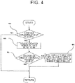
- FIG. 4 is a flowchart which shows a switching procedure of the directional switching valves 30a to 30d in the first embodiment.
- the controller 20 determines whether the on-off valves 25a to 25d are closed in the step 40a. To be more specific, the controller 20 determines whether the on-off valves 25a to 25d are closed based on the displacement amount sent from the displacement sensors 16a to 16d. When the on-off valves 25a to 25d are not closed (step 40a/No), since the directional switching valves 30a to 30d are not switched, processing of that time is completed.
- step 40a/Yes When the on-off valves 25a to 25d are closed namely when the displacement amount is zero (step 40a/Yes), the process proceeds to the step 40b, and the controller 20 acquires operation a number of times N1, N2, N3, N4 of the on-off valves 25a to 25d from the recording device 10, and thereafter executes threshold determination of whether each operation number of times has reached the prescribed value S1 which is a threshold value in the step 40c.
- the process proceeds to the step 40d, and the controller 20 imparts a command to the directional switching valves 30a, 30c connected to the on-off valves 25a, 25c and switches the directional switching valves 30a, 30c from the position A to the position B. That is to say, the on-off valves 25a, 25c and the actuator 5b communicate with each other through the directional switching valves 30a, 30c.
- FIG. 5 is a drawing which shows a relation between the working time of a vehicle body and the operation number of times of on-off valves in a prior art.
- FIG. 6 shows the replacement timing of the on-off valves in the prior art, and the timing of expiration of the lifetime does not agree between the on-off valves 25a, 25c and the on-off valves 25b, 25d as shown in FIG. 6 . Therefore, it is not possible to replace the on-off valves 25a to 25d at the same timing.
- FIG. 7 shows a relation between the working time of a vehicle body and the operation number of times of the on-off valves in the first embodiment.
- the directional switching valves 30a to 30d are switched when the operation number of times of the on-off valves 25a to 25d reaches the prescribed value S1
- FIG. 8 shows this situation.
- FIG. 8 shows the replacement timing of the on-off valves in the first embodiment.
- the lifetime of the on-off valves 25a to 25d expires at the same timing (timing identifiable to be the same).
- the wear amount while the on-off valves 25a to 25d are operated is averaged, excess lifetime of the on-off valves 25a to 25d is not dispersed.
- all of the on-off valves 25a to 25d can be replaced at the same timing, and the number of times of maintenance and the maintenance cost can be reduced.
- the lifetime ratio and the maintenance timing ratio of the on-off valves 25a to 25d and the directional switching valves 30a to 30d can be determined by imparting a suitable first allowable deviation amount ⁇ according to the expression (1) described above.
- the recording device 10 records data of the clock time when the operation number of times of any one of the on-off valves 25a to 25d reaches the average value of the operation number of times of the on-off valves 25a to 25d, and outputs elapsed time from the clock time to the controller 20 point by point.
- the controller 20 issues a switching command to a directional switching valve connected to an on-off valve whose number of times of operation is the largest among the on-off valves 25a to 25d and to a directional switching valve connected to an on-off valve whose number of times of operation is the smallest, and switches these directional switching valves from the position A to the position B or from the position C to the position D.
- the feature of a second embodiment is that the controller 20 imparts a switching command to the directional switching valves 30a to 30d based on a cumulative value of products of the passing flow rate and the differential pressure between front and rear sides of the on-off valves 25a to 25d.
- the detail of processing by the controller 20 will be hereinafter explained.
- FIG. 9 is a block diagram 41f of control processing executed by the controller 20 in the second embodiment.
- the controller 20 calculates differential pressure ⁇ p between front and rear sides of the on-off valves 25a to 25d (41f-2), and obtains a square root of the differential pressure ⁇ p between front and rear sides (41f-3). Also, the controller 20 acquires a displacement amount of the on-off valves 25a to 25d (41f-4), and obtains an open area of the on-off valves 25a to 25d (41f-5).
- the controller 20 obtains a passing flow rate Q of the on-off valves 25a to 25d (41f-7) from the square root of the differential pressure ⁇ p between front and rear sides (41f-3), the open area of the on-off valves 25a to 25d (41f-5), and a flow rate factor (41f-6).
- the controller 20 obtains Q ⁇ P that is a product of the differential pressure AP between front and rear sides (41f-2) and the passing flow rate Q (41f-7) with respect to each of the on-off valves 25a to 25d (41f-8), adds cumulative values Sqp1 to Sqp4 of Q ⁇ P (41f-9) of one cycle before to a value of each of Q ⁇ P (41f-10), and obtains new cumulative values Spq1 to Spq4 of Q ⁇ P of the on-off valves 25a to 25d (41f-11). Thereafter, the controller 20 adds a prescribed second allowable deviation amount ⁇ (refer to FIG. 13 ) to an average value of the cumulative values Sqp1 to Sqp4, and calculates a prescribed value S2.
- the controller 20 issues a switching command to a directional switching valve connected to an on-off valve whose cumulative values Sqp1 to Sqp4 of Q ⁇ P has exceeded the prescribed value S2 and to a directional switching valve connected to an on-off valve whose cumulative value of Q ⁇ P is the smallest.
- FIG. 10 is a flowchart which shows a switching procedure of the directional switching valves 30a to 30d by the controller 20 in the second embodiment.
- the controller 20 determines whether the on-off valves 25a to 25d are closed in the step 41a.
- the on-off valves 25a to 25d are not closed, namely when the displacement amount is not zero (step 41a/No), since the directional switching valves 30a to 30d are not switched, processing of that time is finished.
- step 41b the controller 20 acquires the cumulative values Sqp1 to Sqp4 of Q ⁇ P of the on-off valves 25a to 25d, and executes threshold determination of whether each value of the cumulative values Sqp1 to Sqp4 is equal to or greater than the prescribed value S2 in the step 41c.
- the process proceeds to the step 41d, and the controller 20 imparts a command to the directional switching valves 30a, 30c connected to the on-off valves 25a, 25c respectively, and switches the directional switching valves 30a, 30c from the position A to the position B. That is to say, the on-off valves 25a, 25c and the actuator 5b communicate with each other through the directional switching valves 30a, 30c.
- FIG. 11 is a drawing which shows a relation between the working time of a vehicle body and the cumulative value of Q ⁇ P of on-off valves in a prior art.
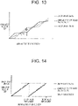
- FIG. 13 shows a relation between the working time of a vehicle body and the cumulative value of Q ⁇ P of on-off valves in the second embodiment.
- FIG. 14 shows this situation.
- FIG. 14 shows the replacement timing of the on-off valves in the second embodiment.
- the risk of the wear caused by erosion is also averaged, and the lifetime of the on-off valves 25a to 25d expires at the same timing (timing identifiable to be the same).
- all of the on-off valves 25a to 25d can be replaced at the same timing, and the number of times of maintenance and the maintenance cost can be reduced.
- step 41c of FIG. 10 even when processing of executing threshold determination whether a second specified time ⁇ 2 (refer to FIG. 13 ) has elapsed after clock time when the cumulative values Sqp1 to Sqp4 of Q ⁇ P of the on-off valves 25a to 25d reach the average value of the cumulative values of Q ⁇ P is applied instead of processing of executing threshold determination whether the cumulative values Sqp1 to Sqp4 of Q ⁇ P of the on-off valves 25a to 25d are equal to or greater than the prescribed value S2 respectively, actions and effects similar to those of the second embodiment can be exerted.
- the recording device 10 records data of the clock time when a cumulative value of Q ⁇ P of any one of the on-off valves 25a to 25d reaches the average value of the cumulative values of Q ⁇ P, and outputs elapsed time from the clock time to the controller 20 point by point.
- the controller 20 issues a switching command to a directional switching valve connected to an on-off valve whose cumulative value of Q ⁇ P is the largest among the on-off valves 25a to 25d and to a directional switching valve connected to an on-off valve whose cumulative value of Q ⁇ P is the smallest, and switches these directional switching valves from the position A to the position B or from the position C to the position D.
- the feature of a third embodiment is that the controller 20 imparts a switching command to the directional switching valves 30a to 30d based on elapsed time from the clock time when switching of the directional switching valves 30a to 30d occurred last time.
- the detail of processing by the controller 20 will be hereinafter explained.
- FIG. 15 is a flowchart which shows a switching procedure of the directional switching valves 30a to 30d by the controller 20 in the third embodiment.
- the controller 20 determines in the step 42a whether the on-off valves 25a to 25d are closed.
- the on-off valves 25a to 25d are not closed, namely when the displacement amount is not zero (step 42a/No), since the directional switching valves 30a to 30d are not switched, processing of that time is finished.
- the process proceeds to the step 42b, the controller 20 acquires elapsed time T after clock time when switching occurred, and executes threshold determination in the step 42c whether the elapsed time T has reached a third specified time ST determined beforehand.
- the third specified time ST in this case may be a value obtained by analyzing the motion of the vehicle body used, and a value obtained by measuring the actuator working time of the actual vehicle body and being determined after considering the measurement result, for example.
- the controller 20 proceeds to the step 42d, and switches the directional switching valves 30a to 30d. Also, processing of the present flowchart is executed repeatedly at an interval of 0.1 second, for example, while the working machine works.
- FIG. 16 shows a relation between the working time of a vehicle body and the operation number of times of on-off valves in the third embodiment.
- the operation number of times of the on-off valves 25a to 25d is averaged since the directional switching valves 30a to 30d are switched every third specified time ST.
- the operation number of times of the on-off valves 25a to 25d takes the average value. Therefore, in all regions of the graph, the operation number of times of the on-off valves 25a to 25d can be averaged in a range of average value ⁇ ( ⁇ -1)/(2( ⁇ +1)).
- FIG. 17 is a drawing which shows the replacement timing of on-off valves in the third embodiment.
- the lifetime of the on-off valves 25a to 25d expires at the same timing (timing identifiable to be the same).
- the wear amount while the on-off valves 25a to 25d are operated is averaged, excess lifetime of the on-off valves 25a to 25d is not dispersed.
- all of the on-off valves 25a to 25d can be replaced at the same timing, and the number of times of maintenance and the maintenance cost can be reduced.
- the third embodiment since it is configured to switch the directional switching valves 30a to 30d by the elapsed time T, it is advantageous in that the displacement sensors 16a to 16d and the pressure sensors 15a to 151 shown in FIGS. 2 , 3 are not required.
- the feature of a fourth embodiment is to be configured to execute switching control of the directional switching valves employing both of the first embodiment and the second embodiment. Since switching control of the directional switching valves by the first embodiment and switching control of the directional switching valves by the third embodiment may possibly conflict with each other, it is concerned that control hunting may occur. Therefore, in order to prevent control hunting, according to the fourth embodiment, the controller 20 executes preference control described below.
- the controller 20 defines the excess lifetime ratio S3 on operation number of times and the excess lifetime ratio S4 on cumulative value of Q ⁇ P respectively, and determines which command based on determination of the operation number of times (the first condition) or the cumulative value of Q ⁇ P (the second condition) is to be given priority from the magnitude relation thereof.
- the detail of control by the controller 20 will be hereinafter explained.
- FIG. 18 is a flowchart which shows a switching procedure of the directional switching valves 30a to 30d by the controller 20 in the fourth embodiment.
- the controller 20 determines in the step 43a whether the on-off valves 25a to 25d are closed.
- the on-off valves 25a to 25d are not closed, namely when the displacement amount is not zero (step 43a/No), since the directional switching valves 30a to 30d are not switched, processing of that time is finished.
- the controller 20 calculates the excess lifetime ratio S3 on operation number of times and the excess lifetime ratio S4 on cumulative value of Q ⁇ P and determines the magnitude relation of the excess lifetime ratio S3 and the excess lifetime ratio S4 in the step 43e.
- step 43f when the excess lifetime ratio S3 on operation number of times is smaller (step 43e/Yes), and the process proceeds to the step 43b when the excess lifetime ratio S4 on cumulative value of Q ⁇ P is smaller. Since the operations thereafter are the same as those of the first embodiment and the second embodiment respectively, explanation thereof will be omitted. Also, processing of the present flowchart is executed repeatedly at an interval of 0.1 second, for example, while the working machine works.
- the number of times of usage of the on-off valves 25a to 25d is averaged considering the state amount history of one with smaller excess lifetime, and therefore, even when controls of both of the first embodiment and the second embodiment are combined, control hunting can be prevented.
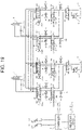
- FIG. 19 is an example of applying the present invention to an open circuit. As shown in FIG. 19 , when the present invention is applied to an open circuit, it is required to substitute open circuit pumps 3a, 3b for the closed circuit pumps 1a, 1b of FIG. 2 and to arrange a tank 4 as a supply source and a discharge destination of the hydraulic oil and switching valves 26a, 26b for switching the supply destination of the hydraulic oil to the actuators 5a, 5b between the rod side or the bottom side.
- respective embodiments described above have a hydraulic circuit configuration including two pumps 1a, 1b, four on-off valves 25a to 25d, and two actuators 5a, 5b as shown in FIG. 2
- the present invention can be applied when a hydraulic circuit configuration includes at least one pump, two on-off valves, and one actuator. In that case, the excess lifetime comes to be averaged between two on-off valves. It is a matter of course and is needless to mention that the present invention can also be applied to a hydraulic circuit configuration including three or more pumps, five or more on-off valves, and three or more actuators.
Landscapes
- Engineering & Computer Science (AREA)
- General Engineering & Computer Science (AREA)
- Mining & Mineral Resources (AREA)
- Civil Engineering (AREA)
- Structural Engineering (AREA)
- Physics & Mathematics (AREA)
- Fluid Mechanics (AREA)
- Mechanical Engineering (AREA)
- Chemical & Material Sciences (AREA)
- Analytical Chemistry (AREA)
- Fluid-Pressure Circuits (AREA)
- Operation Control Of Excavators (AREA)
Claims (10)
- Dispositif d'entraînement hydraulique pour une machine de chantier, comprenant :une pompe hydraulique (1a, 1b) ;un actionneur (5a, 5b) entraîné par une huile sous pression provenant de la pompe hydraulique (1a, 1b) ;une première vanne marche-arrêt (25a, 25c) ouvrant/fermant un passage d'écoulement entre la pompe hydraulique (1a, 1b) et l'actionneur (5a, 5b) ;une seconde vanne marche-arrêt (25b, 25d) agencée parallèlement à la première vanne marche-arrêt (25a, 25c) et ouvrant/fermant un passage d'écoulement entre la pompe hydraulique (1a, 1b) et l'actionneur (5a, 5b) ;une première vanne de commutation directionnelle (30a, 30c) capable de commuter entre une première position et une deuxième position, la première position permettant à la première vanne marche-arrêt (25a, 25c) et à l'actionneur (5a, 5b) de communiquer l'une avec l'autre, et la deuxième position coupant la première vanne marche-arrêt (25a, 25c) et l'actionneur (5a, 5b) l'une de l'autre ;une seconde vanne de commutation directionnelle (30b, 30d) capable de commuter entre une troisième position et une quatrième position, la troisième position coupant la seconde vanne marche-arrêt (25b, 25d) et l'actionneur (5a, 5b) l'une de l'autre, et la quatrième position permettant à la seconde vanne marche-arrêt (25b, 25d) et à l'actionneur (5a, 5b) de commuter l'une avec l'autre ;un dispositif d'enregistrement (10) enregistrant un état d'actionnement de la première vanne marche-arrêt (25a, 25c) et de la seconde vanne marche-arrêt (25b, 25d) avec un laps de temps ; etun contrôleur (20) commandant un actionnement de commutation de la première vanne de commutation directionnelle (30a, 30c) et de la seconde vanne de commutation directionnelle (30b, 30d) sur la base de données historiques par rapport à un état d'actionnement de la première vanne marche-arrêt (25a, 25c) et de la seconde vanne marche-arrêt (25b, 25d) enregistré dans le dispositif d'enregistrement (10),dans lequelle contrôleur (20) ouvre la première vanne marche-arrêt (25a, 25c), ferme la seconde vanne marche-arrêt (25b, 25d), commute la première vanne de commutation directionnelle (30a, 30c) vers la première position, commute la seconde vanne de commutation directionnelle (30b, 30d) vers la troisième position, alimente ainsi une huile sous pression provenant de la pompe hydraulique (1a, 1b) depuis la première vanne marche-arrêt (25a, 25c) jusqu'à l'actionneur (5a, 5b) via la première vanne de commutation directionnelle (30a, 30c), et quand les données historiques de la première vanne marche-arrêt (25a, 25c) sont déterminées comme satisfaisant une condition prescrite, ferme la première vanne marche-arrêt (25a, 25c), ouvre la seconde vanne marche-arrêt (25b, 25d), commute la première vanne de commutation directionnelle (30a, 30c) vers la deuxième position, commute la seconde vanne de commutation directionnelle (30b, 30d) vers la quatrième position, et alimente ainsi une huile sous pression provenant de la pompe hydraulique (1a, 1b) depuis la seconde vanne marche-arrêt (25b, 25d) jusqu'à l'actionneur (5a, 5b) via la seconde vanne de commutation directionnelle (30b, 30d).
- Dispositif d'entraînement hydraulique pour une machine de chantier selon la revendication 1,
dans lequel, quand la première vanne marche-arrêt (25a, 25c) est fermée, le contrôleur (20) détermine si les données historiques de la première vanne marche-arrêt (25a, 25c) satisfont la condition prescrite. - Dispositif d'entraînement hydraulique pour une machine de chantier selon la revendication 1,dans lequel le dispositif d'enregistrement (10) enregistre un nombre de fois d'actionnement de chacune de la première vanne marche-arrêt (25a, 25c) et de la seconde vanne marche-arrêt (25b, 25d) à titre de données historiques, etle contrôleur (20) détermine que la condition prescrite est satisfaite quand le nombre de fois d'actionnement de la première vanne marche-arrêt (25a, 25c) atteint une valeur prescrite.
- Dispositif d'entraînement hydraulique pour une machine de chantier selon la revendication 3,
dans lequel la valeur prescrite est une valeur obtenue en ajoutant une quantité de déviation admissible à une valeur moyenne du nombre de fois d'actionnement de la première vanne marche-arrêt (25a, 25c) et du nombre de fois d'actionnement de la seconde vanne marche-arrêt (25b, 25d). - Dispositif d'entraînement hydraulique pour une machine de chantier selon la revendication 1,dans lequel le dispositif d'enregistrement (10) enregistre un nombre de fois d'actionnement de chacune de la première vanne marche-arrêt (25a, 25c) et de la seconde vanne marche-arrêt (25b, 25d) à titre de données historiques, etle contrôleur (20) détermine que la condition prescrite est satisfaite quand un temps spécifié s'écoule après un point temporel quand le nombre de fois d'actionnement de la première vanne marche-arrêt (25a, 25c) atteint une valeur moyenne du nombre de fois d'actionnement de la première vanne marche-arrêt (25a, 25c) et du nombre de fois d'actionnement de la seconde vanne marche-arrêt (25b, 25d).
- Dispositif d'entraînement hydraulique pour une machine de chantier selon la revendication 1, comprenant en outre :une pluralité de capteurs de déplacement (16a-16d) et une pluralité de capteurs de pression (15a-15l), le capteur de déplacement (16a-16d) détectant une amplitude de déplacement de la première vanne marche-arrêt (25a, 25c) et de la seconde vanne marche-arrêt (25b, 25d), le capteur de pression (15a-15l) détectant une pression devant/derrière la première vanne marche-arrêt (25a, 25c) et la seconde vanne marche-arrêt (25b, 25d), dans lequel le dispositif d'enregistrement (10) enregistre l'amplitude de déplacement de la première vanne marche-arrêt (25a, 25c) et de la seconde vanne marche-arrêt (25b, 25d) à titre de données historiques sur la base de signaux de détection provenant de la pluralité de capteurs de déplacement (16a-16d), et enregistre la pression devant/derrière la première vanne marche-arrêt (25a, 25c) et la seconde vanne marche-arrêt (25b, 25d) à titre de données historiques sur la base de signaux de détection provenant de la pluralité de capteurs de pression (15a-15l),le contrôleur (20) calcule chaque pression différentielle entre un côté avant et un côté arrière de la première vanne marche-arrêt (25a, 25c) et de la seconde vanne marche-arrêt (25b, 25d) sur la base de la pression devant/derrière la première vanne marche-arrêt (25a, 25c) et la seconde vanne marche-arrêt (25b, 25d) enregistrée dans le dispositif d'enregistrement (10), calcule chaque aire d'ouverture de la première vanne marche-arrêt (25a, 25c) et de la seconde vanne marche-arrêt (25b, 25d) sur la base de l'amplitude de déplacement de la première vanne marche-arrêt (25a, 25c) et de la seconde vanne marche-arrêt (25b, 25d) enregistrée dans le dispositif d'enregistrement (10), calcule chaque débit de passage de la première vanne marche-arrêt (25a, 25c) et de la seconde vanne marche-arrêt (25b, 25d) sur la base de chaque pression différentielle entre un côté avant et un côté arrière et de chaque dite aire d'ouverture calculée, et calcule une valeur cumulative de produits de la pression différentielle entre un côté avant et un côté arrière et le débit de passage calculé pour chacune de la première vanne marche-arrêt (25a, 25c) et de la seconde vanne marche-arrêt (25b, 25d), etle contrôleur (20) détermine que la condition prescrite est satisfaite quand la valeur cumulative de la première vanne marche-arrêt (25a, 25c) devient égale ou supérieure à une valeur prescrite.
- Dispositif d'entraînement hydraulique pour une machine de chantier selon la revendication 6,
dans lequel la valeur prescrite est une valeur obtenue en ajoutant une amplitude de déviation admissible à une valeur moyenne de la valeur cumulative de la première vanne marche-arrêt (25a, 25c) et de la valeur cumulative de la seconde vanne marche-arrêt (25b, 25d). - Dispositif d'entraînement hydraulique pour une machine de chantier selon la revendication 6,
dans lequel le contrôleur (20) détermine que la condition prescrite est satisfaite quand un temps spécifié s'écoule après un point temporel quand la valeur cumulative de la première vanne marche-arrêt (25a, 25c) atteint une valeur moyenne de la valeur cumulative de la première vanne marche-arrêt (25a, 25c) et de la valeur cumulative de la seconde vanne marche-arrêt (25b, 25d). - Dispositif d'entraînement hydraulique pour une machine de chantier selon la revendication 1,dans lequel le dispositif d'enregistrement (10) enregistre un temps écoulé après une commutation de la première vanne marche-arrêt (25a, 25c) et de la seconde vanne marche-arrêt (25b, 25d) à titre de données historiques, etle contrôleur (20) détermine que la condition prescrite est satisfaite quand le temps écoulé de la première vanne marche-arrêt (25a, 25c) s'écoule pendant un temps spécifié.
- Dispositif d'entraînement hydraulique pour une machine de chantier selon la revendication 1,dans lequel une première condition et une seconde condition sont définies à titre de condition prescrite, etle contrôleur (20) détermine si les données historiques de la première vanne marche-arrêt (25a, 25c) satisfont une condition sélectionnée parmi la première condition et la seconde condition.
Applications Claiming Priority (2)
| Application Number | Priority Date | Filing Date | Title |
|---|---|---|---|
| JP2018151069A JP6902508B2 (ja) | 2018-08-10 | 2018-08-10 | 作業機械の油圧駆動装置 |
| PCT/JP2019/030767 WO2020031974A1 (fr) | 2018-08-10 | 2019-08-05 | Dispositif d'entraînement hydraulique pour engin de chantier |
Publications (3)
| Publication Number | Publication Date |
|---|---|
| EP3744988A1 EP3744988A1 (fr) | 2020-12-02 |
| EP3744988A4 EP3744988A4 (fr) | 2021-11-10 |
| EP3744988B1 true EP3744988B1 (fr) | 2023-01-18 |
Family
ID=69414812
Family Applications (1)
| Application Number | Title | Priority Date | Filing Date |
|---|---|---|---|
| EP19845986.9A Active EP3744988B1 (fr) | 2018-08-10 | 2019-08-05 | Dispositif d'entraînement hydraulique pour engin de chantier |
Country Status (5)
| Country | Link |
|---|---|
| US (1) | US10907323B1 (fr) |
| EP (1) | EP3744988B1 (fr) |
| JP (1) | JP6902508B2 (fr) |
| CN (1) | CN111788398B (fr) |
| WO (1) | WO2020031974A1 (fr) |
Families Citing this family (4)
| Publication number | Priority date | Publication date | Assignee | Title |
|---|---|---|---|---|
| JP7096178B2 (ja) * | 2019-02-08 | 2022-07-05 | 日立建機株式会社 | 建設機械 |
| US11299866B2 (en) * | 2019-09-24 | 2022-04-12 | Deere & Company | Dozer blade attachment control system and apparatus for a compact track loader |
| EP4660465A1 (fr) | 2023-03-28 | 2025-12-10 | Hitachi Construction Machinery Co., Ltd. | Dispositif d'entraînement hydraulique |
| CN119267198B (zh) * | 2024-12-11 | 2025-03-18 | 杭州安衡迅科技有限公司 | 泵性能测试系统 |
Family Cites Families (15)
| Publication number | Priority date | Publication date | Assignee | Title |
|---|---|---|---|---|
| US4761953A (en) * | 1984-04-18 | 1988-08-09 | Dynamic Hydraulic Systems, Inc. | Hydraulic elevator mechanism |
| CN1190569C (zh) * | 2000-03-31 | 2005-02-23 | 日立建机株式会社 | 机械的数据收集和管理系统 |
| KR100523228B1 (ko) * | 2001-05-08 | 2005-10-20 | 히다치 겡키 가부시키 가이샤 | 작업기계, 작업기계의 고장진단시스템, 작업기계의메인티넌스시스템 |
| JP2005171940A (ja) * | 2003-12-15 | 2005-06-30 | Hitachi Constr Mach Co Ltd | 建設機械のエンジンメンテナンス時期予測装置及び予測方法 |
| JP4735518B2 (ja) * | 2006-11-17 | 2011-07-27 | コベルコクレーン株式会社 | 建設機械用メンテナンス情報管理装置及び建設機械用メンテナンス情報管理方法 |
| KR101953414B1 (ko) * | 2011-10-04 | 2019-02-28 | 가부시키가이샤 히다치 겡키 티에라 | 배기 가스 정화 장치를 구비한 건설 기계용 유압 구동 시스템 |
| US20140227104A1 (en) * | 2011-10-20 | 2014-08-14 | Hitachi Construction Machinery Co., Ltd. | Hydraulic drive system for electrically-operated hydraulic work machine |
| US9068578B2 (en) * | 2011-10-21 | 2015-06-30 | Caterpillar Inc. | Hydraulic system having flow combining capabilities |
| JP2013245787A (ja) * | 2012-05-28 | 2013-12-09 | Hitachi Constr Mach Co Ltd | 作業機械の駆動装置 |
| JP6134614B2 (ja) * | 2013-09-02 | 2017-05-24 | 日立建機株式会社 | 作業機械の駆動装置 |
| ES2731799T3 (es) * | 2014-08-06 | 2019-11-19 | Padoan S R L | Aparato y método para el control de sistemas hidráulicos |
| CN105986592B (zh) * | 2015-02-11 | 2021-07-13 | 住友建机株式会社 | 挖土机及挖土机的管理装置 |
| JP6474702B2 (ja) | 2015-09-07 | 2019-02-27 | 日立建機株式会社 | 作業機械の駆動装置 |
| CN106246622A (zh) * | 2016-08-22 | 2016-12-21 | 王恩峰 | 变频液压变加载系统 |
| JP6710150B2 (ja) * | 2016-11-24 | 2020-06-17 | 日立建機株式会社 | 建設機械 |
-
2018
- 2018-08-10 JP JP2018151069A patent/JP6902508B2/ja active Active
-
2019
- 2019-08-05 US US16/976,576 patent/US10907323B1/en active Active
- 2019-08-05 EP EP19845986.9A patent/EP3744988B1/fr active Active
- 2019-08-05 CN CN201980016476.5A patent/CN111788398B/zh active Active
- 2019-08-05 WO PCT/JP2019/030767 patent/WO2020031974A1/fr not_active Ceased
Also Published As
| Publication number | Publication date |
|---|---|
| US20210047803A1 (en) | 2021-02-18 |
| JP2020026826A (ja) | 2020-02-20 |
| WO2020031974A1 (fr) | 2020-02-13 |
| EP3744988A1 (fr) | 2020-12-02 |
| EP3744988A4 (fr) | 2021-11-10 |
| JP6902508B2 (ja) | 2021-07-14 |
| US10907323B1 (en) | 2021-02-02 |
| CN111788398A (zh) | 2020-10-16 |
| CN111788398B (zh) | 2022-06-03 |
Similar Documents
| Publication | Publication Date | Title |
|---|---|---|
| KR101693129B1 (ko) | 작업 기계 | |
| EP3744988A1 (fr) | Dispositif d'entraînement hydraulique pour engin de chantier | |
| KR101700797B1 (ko) | 경전각 제어 장치 | |
| KR101213528B1 (ko) | 작업 차량 및 작업 차량의 제어 방법 | |
| KR101770674B1 (ko) | 건설기계의 유압 구동 장치 | |
| CN111102255B (zh) | 工程机械的行驶控制系统及工程机械的行驶控制方法 | |
| EP2503065A2 (fr) | Machine de construction hybride | |
| EP3926177B1 (fr) | Engin de chantier | |
| US20120291427A1 (en) | Attachment control apparatus for hydraulic excavator | |
| EP3399190B1 (fr) | Machine de travail | |
| US9784368B2 (en) | Hydraulic control apparatus and method | |
| KR20180033266A (ko) | 작업 기계 | |
| US20130160439A1 (en) | Flow rate control device for variable displacement type hydraulic pump for construction equipment | |
| US20120093624A1 (en) | Work machine and control method for work machines | |
| EP2677180A1 (fr) | Dispositif d'entraînement hydraulique d'engin de chantier | |
| EP2503064A2 (fr) | Machine de construction hybride | |
| US12018459B2 (en) | Hydraulic control system for a working machine | |
| JP6474702B2 (ja) | 作業機械の駆動装置 | |
| JP7085996B2 (ja) | 作業機械および作業機械の制御方法 | |
| JP6502217B2 (ja) | 作業機の油圧システム | |
| JP2020143591A (ja) | 油圧ポンプの故障診断装置、故障診断装置を備える建設機械、故障診断方法および故障診断プログラム | |
| WO2019139104A1 (fr) | Machine de construction | |
| US12196230B2 (en) | Control device and hydraulic system including the same | |
| JP2014190514A (ja) | 建設機械のポンプ制御装置 | |
| JP2015151711A (ja) | 建設機械のポンプ制御装置 |
Legal Events
| Date | Code | Title | Description |
|---|---|---|---|
| STAA | Information on the status of an ep patent application or granted ep patent |
Free format text: STATUS: THE INTERNATIONAL PUBLICATION HAS BEEN MADE |
|
| PUAI | Public reference made under article 153(3) epc to a published international application that has entered the european phase |
Free format text: ORIGINAL CODE: 0009012 |
|
| STAA | Information on the status of an ep patent application or granted ep patent |
Free format text: STATUS: REQUEST FOR EXAMINATION WAS MADE |
|
| 17P | Request for examination filed |
Effective date: 20200827 |
|
| AK | Designated contracting states |
Kind code of ref document: A1 Designated state(s): AL AT BE BG CH CY CZ DE DK EE ES FI FR GB GR HR HU IE IS IT LI LT LU LV MC MK MT NL NO PL PT RO RS SE SI SK SM TR |
|
| AX | Request for extension of the european patent |
Extension state: BA ME |
|
| A4 | Supplementary search report drawn up and despatched |
Effective date: 20211008 |
|
| RIC1 | Information provided on ipc code assigned before grant |
Ipc: F15B 19/00 20060101ALI20211004BHEP Ipc: F15B 21/08 20060101ALI20211004BHEP Ipc: F15B 11/17 20060101ALI20211004BHEP Ipc: F15B 7/00 20060101ALI20211004BHEP Ipc: F15B 11/02 20060101ALI20211004BHEP Ipc: E02F 9/22 20060101ALI20211004BHEP Ipc: F15B 20/00 20060101AFI20211004BHEP |
|
| DAV | Request for validation of the european patent (deleted) | ||
| DAX | Request for extension of the european patent (deleted) | ||
| RIC1 | Information provided on ipc code assigned before grant |
Ipc: F15B 19/00 20060101ALI20220802BHEP Ipc: F15B 21/08 20060101ALI20220802BHEP Ipc: F15B 11/17 20060101ALI20220802BHEP Ipc: F15B 7/00 20060101ALI20220802BHEP Ipc: F15B 11/02 20060101ALI20220802BHEP Ipc: E02F 9/22 20060101ALI20220802BHEP Ipc: F15B 20/00 20060101AFI20220802BHEP |
|
| GRAP | Despatch of communication of intention to grant a patent |
Free format text: ORIGINAL CODE: EPIDOSNIGR1 |
|
| STAA | Information on the status of an ep patent application or granted ep patent |
Free format text: STATUS: GRANT OF PATENT IS INTENDED |
|
| INTG | Intention to grant announced |
Effective date: 20220912 |
|
| GRAS | Grant fee paid |
Free format text: ORIGINAL CODE: EPIDOSNIGR3 |
|
| GRAA | (expected) grant |
Free format text: ORIGINAL CODE: 0009210 |
|
| STAA | Information on the status of an ep patent application or granted ep patent |
Free format text: STATUS: THE PATENT HAS BEEN GRANTED |
|
| AK | Designated contracting states |
Kind code of ref document: B1 Designated state(s): AL AT BE BG CH CY CZ DE DK EE ES FI FR GB GR HR HU IE IS IT LI LT LU LV MC MK MT NL NO PL PT RO RS SE SI SK SM TR |
|
| REG | Reference to a national code |
Ref country code: GB Ref legal event code: FG4D |
|
| REG | Reference to a national code |
Ref country code: DE Ref legal event code: R096 Ref document number: 602019024638 Country of ref document: DE |
|
| REG | Reference to a national code |
Ref country code: CH Ref legal event code: EP |
|
| REG | Reference to a national code |
Ref country code: AT Ref legal event code: REF Ref document number: 1544857 Country of ref document: AT Kind code of ref document: T Effective date: 20230215 Ref country code: IE Ref legal event code: FG4D |
|
| REG | Reference to a national code |
Ref country code: LT Ref legal event code: MG9D |
|
| REG | Reference to a national code |
Ref country code: NL Ref legal event code: MP Effective date: 20230118 |
|
| REG | Reference to a national code |
Ref country code: AT Ref legal event code: MK05 Ref document number: 1544857 Country of ref document: AT Kind code of ref document: T Effective date: 20230118 |
|
| PG25 | Lapsed in a contracting state [announced via postgrant information from national office to epo] |
Ref country code: NL Free format text: LAPSE BECAUSE OF FAILURE TO SUBMIT A TRANSLATION OF THE DESCRIPTION OR TO PAY THE FEE WITHIN THE PRESCRIBED TIME-LIMIT Effective date: 20230118 |
|
| PG25 | Lapsed in a contracting state [announced via postgrant information from national office to epo] |
Ref country code: RS Free format text: LAPSE BECAUSE OF FAILURE TO SUBMIT A TRANSLATION OF THE DESCRIPTION OR TO PAY THE FEE WITHIN THE PRESCRIBED TIME-LIMIT Effective date: 20230118 Ref country code: PT Free format text: LAPSE BECAUSE OF FAILURE TO SUBMIT A TRANSLATION OF THE DESCRIPTION OR TO PAY THE FEE WITHIN THE PRESCRIBED TIME-LIMIT Effective date: 20230518 Ref country code: NO Free format text: LAPSE BECAUSE OF FAILURE TO SUBMIT A TRANSLATION OF THE DESCRIPTION OR TO PAY THE FEE WITHIN THE PRESCRIBED TIME-LIMIT Effective date: 20230418 Ref country code: LV Free format text: LAPSE BECAUSE OF FAILURE TO SUBMIT A TRANSLATION OF THE DESCRIPTION OR TO PAY THE FEE WITHIN THE PRESCRIBED TIME-LIMIT Effective date: 20230118 Ref country code: LT Free format text: LAPSE BECAUSE OF FAILURE TO SUBMIT A TRANSLATION OF THE DESCRIPTION OR TO PAY THE FEE WITHIN THE PRESCRIBED TIME-LIMIT Effective date: 20230118 Ref country code: HR Free format text: LAPSE BECAUSE OF FAILURE TO SUBMIT A TRANSLATION OF THE DESCRIPTION OR TO PAY THE FEE WITHIN THE PRESCRIBED TIME-LIMIT Effective date: 20230118 Ref country code: ES Free format text: LAPSE BECAUSE OF FAILURE TO SUBMIT A TRANSLATION OF THE DESCRIPTION OR TO PAY THE FEE WITHIN THE PRESCRIBED TIME-LIMIT Effective date: 20230118 Ref country code: AT Free format text: LAPSE BECAUSE OF FAILURE TO SUBMIT A TRANSLATION OF THE DESCRIPTION OR TO PAY THE FEE WITHIN THE PRESCRIBED TIME-LIMIT Effective date: 20230118 |
|
| PG25 | Lapsed in a contracting state [announced via postgrant information from national office to epo] |
Ref country code: SE Free format text: LAPSE BECAUSE OF FAILURE TO SUBMIT A TRANSLATION OF THE DESCRIPTION OR TO PAY THE FEE WITHIN THE PRESCRIBED TIME-LIMIT Effective date: 20230118 Ref country code: PL Free format text: LAPSE BECAUSE OF FAILURE TO SUBMIT A TRANSLATION OF THE DESCRIPTION OR TO PAY THE FEE WITHIN THE PRESCRIBED TIME-LIMIT Effective date: 20230118 Ref country code: IS Free format text: LAPSE BECAUSE OF FAILURE TO SUBMIT A TRANSLATION OF THE DESCRIPTION OR TO PAY THE FEE WITHIN THE PRESCRIBED TIME-LIMIT Effective date: 20230518 Ref country code: GR Free format text: LAPSE BECAUSE OF FAILURE TO SUBMIT A TRANSLATION OF THE DESCRIPTION OR TO PAY THE FEE WITHIN THE PRESCRIBED TIME-LIMIT Effective date: 20230419 Ref country code: FI Free format text: LAPSE BECAUSE OF FAILURE TO SUBMIT A TRANSLATION OF THE DESCRIPTION OR TO PAY THE FEE WITHIN THE PRESCRIBED TIME-LIMIT Effective date: 20230118 |
|
| REG | Reference to a national code |
Ref country code: DE Ref legal event code: R097 Ref document number: 602019024638 Country of ref document: DE |
|
| PG25 | Lapsed in a contracting state [announced via postgrant information from national office to epo] |
Ref country code: SM Free format text: LAPSE BECAUSE OF FAILURE TO SUBMIT A TRANSLATION OF THE DESCRIPTION OR TO PAY THE FEE WITHIN THE PRESCRIBED TIME-LIMIT Effective date: 20230118 Ref country code: RO Free format text: LAPSE BECAUSE OF FAILURE TO SUBMIT A TRANSLATION OF THE DESCRIPTION OR TO PAY THE FEE WITHIN THE PRESCRIBED TIME-LIMIT Effective date: 20230118 Ref country code: EE Free format text: LAPSE BECAUSE OF FAILURE TO SUBMIT A TRANSLATION OF THE DESCRIPTION OR TO PAY THE FEE WITHIN THE PRESCRIBED TIME-LIMIT Effective date: 20230118 Ref country code: DK Free format text: LAPSE BECAUSE OF FAILURE TO SUBMIT A TRANSLATION OF THE DESCRIPTION OR TO PAY THE FEE WITHIN THE PRESCRIBED TIME-LIMIT Effective date: 20230118 Ref country code: CZ Free format text: LAPSE BECAUSE OF FAILURE TO SUBMIT A TRANSLATION OF THE DESCRIPTION OR TO PAY THE FEE WITHIN THE PRESCRIBED TIME-LIMIT Effective date: 20230118 |
|
| PLBE | No opposition filed within time limit |
Free format text: ORIGINAL CODE: 0009261 |
|
| STAA | Information on the status of an ep patent application or granted ep patent |
Free format text: STATUS: NO OPPOSITION FILED WITHIN TIME LIMIT |
|
| PG25 | Lapsed in a contracting state [announced via postgrant information from national office to epo] |
Ref country code: SK Free format text: LAPSE BECAUSE OF FAILURE TO SUBMIT A TRANSLATION OF THE DESCRIPTION OR TO PAY THE FEE WITHIN THE PRESCRIBED TIME-LIMIT Effective date: 20230118 |
|
| 26N | No opposition filed |
Effective date: 20231019 |
|
| PG25 | Lapsed in a contracting state [announced via postgrant information from national office to epo] |
Ref country code: SI Free format text: LAPSE BECAUSE OF FAILURE TO SUBMIT A TRANSLATION OF THE DESCRIPTION OR TO PAY THE FEE WITHIN THE PRESCRIBED TIME-LIMIT Effective date: 20230118 |
|
| PG25 | Lapsed in a contracting state [announced via postgrant information from national office to epo] |
Ref country code: MC Free format text: LAPSE BECAUSE OF FAILURE TO SUBMIT A TRANSLATION OF THE DESCRIPTION OR TO PAY THE FEE WITHIN THE PRESCRIBED TIME-LIMIT Effective date: 20230118 |
|
| REG | Reference to a national code |
Ref country code: CH Ref legal event code: PL |
|
| PG25 | Lapsed in a contracting state [announced via postgrant information from national office to epo] |
Ref country code: MC Free format text: LAPSE BECAUSE OF FAILURE TO SUBMIT A TRANSLATION OF THE DESCRIPTION OR TO PAY THE FEE WITHIN THE PRESCRIBED TIME-LIMIT Effective date: 20230118 |
|
| PG25 | Lapsed in a contracting state [announced via postgrant information from national office to epo] |
Ref country code: LU Free format text: LAPSE BECAUSE OF NON-PAYMENT OF DUE FEES Effective date: 20230805 |
|
| GBPC | Gb: european patent ceased through non-payment of renewal fee |
Effective date: 20230805 |
|
| PG25 | Lapsed in a contracting state [announced via postgrant information from national office to epo] |
Ref country code: LU Free format text: LAPSE BECAUSE OF NON-PAYMENT OF DUE FEES Effective date: 20230805 Ref country code: CH Free format text: LAPSE BECAUSE OF NON-PAYMENT OF DUE FEES Effective date: 20230831 |
|
| REG | Reference to a national code |
Ref country code: BE Ref legal event code: MM Effective date: 20230831 |
|
| REG | Reference to a national code |
Ref country code: IE Ref legal event code: MM4A |
|
| PG25 | Lapsed in a contracting state [announced via postgrant information from national office to epo] |
Ref country code: IT Free format text: LAPSE BECAUSE OF FAILURE TO SUBMIT A TRANSLATION OF THE DESCRIPTION OR TO PAY THE FEE WITHIN THE PRESCRIBED TIME-LIMIT Effective date: 20230118 |
|
| PG25 | Lapsed in a contracting state [announced via postgrant information from national office to epo] |
Ref country code: IE Free format text: LAPSE BECAUSE OF NON-PAYMENT OF DUE FEES Effective date: 20230805 |
|
| PG25 | Lapsed in a contracting state [announced via postgrant information from national office to epo] |
Ref country code: GB Free format text: LAPSE BECAUSE OF NON-PAYMENT OF DUE FEES Effective date: 20230805 |
|
| PG25 | Lapsed in a contracting state [announced via postgrant information from national office to epo] |
Ref country code: IE Free format text: LAPSE BECAUSE OF NON-PAYMENT OF DUE FEES Effective date: 20230805 Ref country code: GB Free format text: LAPSE BECAUSE OF NON-PAYMENT OF DUE FEES Effective date: 20230805 Ref country code: FR Free format text: LAPSE BECAUSE OF NON-PAYMENT OF DUE FEES Effective date: 20230831 |
|
| PG25 | Lapsed in a contracting state [announced via postgrant information from national office to epo] |
Ref country code: BE Free format text: LAPSE BECAUSE OF NON-PAYMENT OF DUE FEES Effective date: 20230831 |
|
| PG25 | Lapsed in a contracting state [announced via postgrant information from national office to epo] |
Ref country code: BG Free format text: LAPSE BECAUSE OF FAILURE TO SUBMIT A TRANSLATION OF THE DESCRIPTION OR TO PAY THE FEE WITHIN THE PRESCRIBED TIME-LIMIT Effective date: 20230118 |
|
| PG25 | Lapsed in a contracting state [announced via postgrant information from national office to epo] |
Ref country code: BG Free format text: LAPSE BECAUSE OF FAILURE TO SUBMIT A TRANSLATION OF THE DESCRIPTION OR TO PAY THE FEE WITHIN THE PRESCRIBED TIME-LIMIT Effective date: 20230118 |
|
| PG25 | Lapsed in a contracting state [announced via postgrant information from national office to epo] |
Ref country code: CY Free format text: LAPSE BECAUSE OF FAILURE TO SUBMIT A TRANSLATION OF THE DESCRIPTION OR TO PAY THE FEE WITHIN THE PRESCRIBED TIME-LIMIT; INVALID AB INITIO Effective date: 20190805 |
|
| PG25 | Lapsed in a contracting state [announced via postgrant information from national office to epo] |
Ref country code: HU Free format text: LAPSE BECAUSE OF FAILURE TO SUBMIT A TRANSLATION OF THE DESCRIPTION OR TO PAY THE FEE WITHIN THE PRESCRIBED TIME-LIMIT; INVALID AB INITIO Effective date: 20190805 |
|
| PGFP | Annual fee paid to national office [announced via postgrant information from national office to epo] |
Ref country code: DE Payment date: 20250702 Year of fee payment: 7 |
|
| PG25 | Lapsed in a contracting state [announced via postgrant information from national office to epo] |
Ref country code: TR Free format text: LAPSE BECAUSE OF FAILURE TO SUBMIT A TRANSLATION OF THE DESCRIPTION OR TO PAY THE FEE WITHIN THE PRESCRIBED TIME-LIMIT Effective date: 20230118 |