EP3745017B1 - Beleuchtungsvorrichtung für einen kraftfahrzeugscheinwerfer - Google Patents
Beleuchtungsvorrichtung für einen kraftfahrzeugscheinwerfer Download PDFInfo
- Publication number
- EP3745017B1 EP3745017B1 EP19177334.0A EP19177334A EP3745017B1 EP 3745017 B1 EP3745017 B1 EP 3745017B1 EP 19177334 A EP19177334 A EP 19177334A EP 3745017 B1 EP3745017 B1 EP 3745017B1
- Authority
- EP
- European Patent Office
- Prior art keywords
- pair
- light guide
- light
- positioning means
- circuit board
- Prior art date
- Legal status (The legal status is an assumption and is not a legal conclusion. Google has not performed a legal analysis and makes no representation as to the accuracy of the status listed.)
- Active
Links
Images


Classifications
-
- F—MECHANICAL ENGINEERING; LIGHTING; HEATING; WEAPONS; BLASTING
- F21—LIGHTING
- F21S—NON-PORTABLE LIGHTING DEVICES; SYSTEMS THEREOF; VEHICLE LIGHTING DEVICES SPECIALLY ADAPTED FOR VEHICLE EXTERIORS
- F21S43/00—Signalling devices specially adapted for vehicle exteriors, e.g. brake lamps, direction indicator lights or reversing lights
- F21S43/20—Signalling devices specially adapted for vehicle exteriors, e.g. brake lamps, direction indicator lights or reversing lights characterised by refractors, transparent cover plates, light guides or filters
- F21S43/27—Attachment thereof
-
- F—MECHANICAL ENGINEERING; LIGHTING; HEATING; WEAPONS; BLASTING
- F21—LIGHTING
- F21S—NON-PORTABLE LIGHTING DEVICES; SYSTEMS THEREOF; VEHICLE LIGHTING DEVICES SPECIALLY ADAPTED FOR VEHICLE EXTERIORS
- F21S41/00—Illuminating devices specially adapted for vehicle exteriors, e.g. headlamps
- F21S41/10—Illuminating devices specially adapted for vehicle exteriors, e.g. headlamps characterised by the light source
- F21S41/19—Attachment of light sources or lamp holders
-
- B—PERFORMING OPERATIONS; TRANSPORTING
- B60—VEHICLES IN GENERAL
- B60Q—ARRANGEMENT OF SIGNALLING OR LIGHTING DEVICES, THE MOUNTING OR SUPPORTING THEREOF OR CIRCUITS THEREFOR, FOR VEHICLES IN GENERAL
- B60Q1/00—Arrangement of optical signalling or lighting devices, the mounting or supporting thereof or circuits therefor
- B60Q1/02—Arrangement of optical signalling or lighting devices, the mounting or supporting thereof or circuits therefor the devices being primarily intended to illuminate the way ahead or to illuminate other areas of way or environments
- B60Q1/04—Arrangement of optical signalling or lighting devices, the mounting or supporting thereof or circuits therefor the devices being primarily intended to illuminate the way ahead or to illuminate other areas of way or environments the devices being headlights
-
- F—MECHANICAL ENGINEERING; LIGHTING; HEATING; WEAPONS; BLASTING
- F21—LIGHTING
- F21S—NON-PORTABLE LIGHTING DEVICES; SYSTEMS THEREOF; VEHICLE LIGHTING DEVICES SPECIALLY ADAPTED FOR VEHICLE EXTERIORS
- F21S41/00—Illuminating devices specially adapted for vehicle exteriors, e.g. headlamps
- F21S41/10—Illuminating devices specially adapted for vehicle exteriors, e.g. headlamps characterised by the light source
- F21S41/14—Illuminating devices specially adapted for vehicle exteriors, e.g. headlamps characterised by the light source characterised by the type of light source
- F21S41/141—Light emitting diodes [LED]
-
- F—MECHANICAL ENGINEERING; LIGHTING; HEATING; WEAPONS; BLASTING
- F21—LIGHTING
- F21S—NON-PORTABLE LIGHTING DEVICES; SYSTEMS THEREOF; VEHICLE LIGHTING DEVICES SPECIALLY ADAPTED FOR VEHICLE EXTERIORS
- F21S41/00—Illuminating devices specially adapted for vehicle exteriors, e.g. headlamps
- F21S41/10—Illuminating devices specially adapted for vehicle exteriors, e.g. headlamps characterised by the light source
- F21S41/14—Illuminating devices specially adapted for vehicle exteriors, e.g. headlamps characterised by the light source characterised by the type of light source
- F21S41/141—Light emitting diodes [LED]
- F21S41/143—Light emitting diodes [LED] the main emission direction of the LED being parallel to the optical axis of the illuminating device
-
- F—MECHANICAL ENGINEERING; LIGHTING; HEATING; WEAPONS; BLASTING
- F21—LIGHTING
- F21S—NON-PORTABLE LIGHTING DEVICES; SYSTEMS THEREOF; VEHICLE LIGHTING DEVICES SPECIALLY ADAPTED FOR VEHICLE EXTERIORS
- F21S41/00—Illuminating devices specially adapted for vehicle exteriors, e.g. headlamps
- F21S41/10—Illuminating devices specially adapted for vehicle exteriors, e.g. headlamps characterised by the light source
- F21S41/19—Attachment of light sources or lamp holders
- F21S41/192—Details of lamp holders, terminals or connectors
-
- F—MECHANICAL ENGINEERING; LIGHTING; HEATING; WEAPONS; BLASTING
- F21—LIGHTING
- F21S—NON-PORTABLE LIGHTING DEVICES; SYSTEMS THEREOF; VEHICLE LIGHTING DEVICES SPECIALLY ADAPTED FOR VEHICLE EXTERIORS
- F21S41/00—Illuminating devices specially adapted for vehicle exteriors, e.g. headlamps
- F21S41/20—Illuminating devices specially adapted for vehicle exteriors, e.g. headlamps characterised by refractors, transparent cover plates, light guides or filters
- F21S41/24—Light guides
-
- F—MECHANICAL ENGINEERING; LIGHTING; HEATING; WEAPONS; BLASTING
- F21—LIGHTING
- F21S—NON-PORTABLE LIGHTING DEVICES; SYSTEMS THEREOF; VEHICLE LIGHTING DEVICES SPECIALLY ADAPTED FOR VEHICLE EXTERIORS
- F21S41/00—Illuminating devices specially adapted for vehicle exteriors, e.g. headlamps
- F21S41/20—Illuminating devices specially adapted for vehicle exteriors, e.g. headlamps characterised by refractors, transparent cover plates, light guides or filters
- F21S41/29—Attachment thereof
-
- F—MECHANICAL ENGINEERING; LIGHTING; HEATING; WEAPONS; BLASTING
- F21—LIGHTING
- F21S—NON-PORTABLE LIGHTING DEVICES; SYSTEMS THEREOF; VEHICLE LIGHTING DEVICES SPECIALLY ADAPTED FOR VEHICLE EXTERIORS
- F21S43/00—Signalling devices specially adapted for vehicle exteriors, e.g. brake lamps, direction indicator lights or reversing lights
- F21S43/10—Signalling devices specially adapted for vehicle exteriors, e.g. brake lamps, direction indicator lights or reversing lights characterised by the light source
- F21S43/13—Signalling devices specially adapted for vehicle exteriors, e.g. brake lamps, direction indicator lights or reversing lights characterised by the light source characterised by the type of light source
- F21S43/14—Light emitting diodes [LED]
-
- F—MECHANICAL ENGINEERING; LIGHTING; HEATING; WEAPONS; BLASTING
- F21—LIGHTING
- F21S—NON-PORTABLE LIGHTING DEVICES; SYSTEMS THEREOF; VEHICLE LIGHTING DEVICES SPECIALLY ADAPTED FOR VEHICLE EXTERIORS
- F21S43/00—Signalling devices specially adapted for vehicle exteriors, e.g. brake lamps, direction indicator lights or reversing lights
- F21S43/10—Signalling devices specially adapted for vehicle exteriors, e.g. brake lamps, direction indicator lights or reversing lights characterised by the light source
- F21S43/19—Attachment of light sources or lamp holders
-
- F—MECHANICAL ENGINEERING; LIGHTING; HEATING; WEAPONS; BLASTING
- F21—LIGHTING
- F21S—NON-PORTABLE LIGHTING DEVICES; SYSTEMS THEREOF; VEHICLE LIGHTING DEVICES SPECIALLY ADAPTED FOR VEHICLE EXTERIORS
- F21S43/00—Signalling devices specially adapted for vehicle exteriors, e.g. brake lamps, direction indicator lights or reversing lights
- F21S43/20—Signalling devices specially adapted for vehicle exteriors, e.g. brake lamps, direction indicator lights or reversing lights characterised by refractors, transparent cover plates, light guides or filters
- F21S43/235—Light guides
- F21S43/236—Light guides characterised by the shape of the light guide
- F21S43/237—Light guides characterised by the shape of the light guide rod-shaped
-
- F—MECHANICAL ENGINEERING; LIGHTING; HEATING; WEAPONS; BLASTING
- F21—LIGHTING
- F21S—NON-PORTABLE LIGHTING DEVICES; SYSTEMS THEREOF; VEHICLE LIGHTING DEVICES SPECIALLY ADAPTED FOR VEHICLE EXTERIORS
- F21S43/00—Signalling devices specially adapted for vehicle exteriors, e.g. brake lamps, direction indicator lights or reversing lights
- F21S43/20—Signalling devices specially adapted for vehicle exteriors, e.g. brake lamps, direction indicator lights or reversing lights characterised by refractors, transparent cover plates, light guides or filters
- F21S43/235—Light guides
- F21S43/247—Light guides with a single light source being coupled into the light guide
-
- F—MECHANICAL ENGINEERING; LIGHTING; HEATING; WEAPONS; BLASTING
- F21—LIGHTING
- F21W—INDEXING SCHEME ASSOCIATED WITH SUBCLASSES F21K, F21L, F21S and F21V, RELATING TO USES OR APPLICATIONS OF LIGHTING DEVICES OR SYSTEMS
- F21W2102/00—Exterior vehicle lighting devices for illuminating purposes
- F21W2102/10—Arrangement or contour of the emitted light
- F21W2102/13—Arrangement or contour of the emitted light for high-beam region or low-beam region
-
- F—MECHANICAL ENGINEERING; LIGHTING; HEATING; WEAPONS; BLASTING
- F21—LIGHTING
- F21Y—INDEXING SCHEME ASSOCIATED WITH SUBCLASSES F21K, F21L, F21S and F21V, RELATING TO THE FORM OR THE KIND OF THE LIGHT SOURCES OR OF THE COLOUR OF THE LIGHT EMITTED
- F21Y2115/00—Light-generating elements of semiconductor light sources
- F21Y2115/10—Light-emitting diodes [LED]
Definitions
- the invention relates to a motor vehicle headlight comprising at least one lighting device according to the invention.
- the EP 2 775 197 A1 discloses a prior art lighting device for motor vehicle headlights.
- the light guide whose light coupling surface is aligned with respect to a light source arranged on a circuit board, is not attached directly to the circuit board itself.
- the materials of the circuit board and the light guide or the light coupling surface which is usually located in close proximity to the light source, expand due to thermal expansion.
- the securing means is designed as a spring-elastic U-shaped clamp, wherein the clamp is detachably arranged on the light guide and the circuit board and grips the light guide and the circuit board and presses them against each other.
- the distance between the light source and the light coupling surface of the light guide remains constant. This compensates for the expansion of the overall system.
- main radiation direction means the direction in which at least one light source emits the strongest or most light due to its directional effect.
- the light coupling surface of the light guide lies in a normal plane to the main emission direction.
- the corresponding means of the at least one first pair of positioning means, which means is arranged on the light guide, is manufactured in one piece with the light guide.
- the light guide is manufactured using an injection molding process.
- the corresponding means of the at least one second pair of positioning means, which means is arranged on the light guide is manufactured in one piece with the light guide.
- the positioning device has at least two, preferably exactly two, first pairs of positioning means.
- the projections can be designed as cylindrical pins, whereby if there is a single such pin - inserted in the opening provided for it - the circuit board or the light guide can still be rotated around the cylindrical pin, which is not desirable.
- the projection of the at least one first pair of positioning means is arranged on the light guide and the opening of the at least one first pair of positioning means is arranged on the circuit board.
- the clamping force caused by the clamping means which presses the circuit board and the light guide against each other, must be greater than the force caused by an expansion of the material of the light guide and the circuit board, caused by an increase in temperature, for example due to the operation of the light source, of the components mentioned.
- the positioning device has at least two, preferably exactly two, second positioning means pairs.
- the stop of the second pair of positioning means is arranged on the light guide and the stop surface of the second pair of positioning means is arranged on the circuit board.
- the projection engages in a form-fitting manner in the corresponding opening.
- the projection penetrates the circuit board in the end position of the light guide on the circuit board.
- the at least one light source is designed as an LED.
- each light-emitting diode can be controlled independently of the other light-emitting diodes.
- Each LED can thus be switched on and off independently of the other LEDs of a light source, and preferably when dimmable
- LEDs can also be dimmed independently of the other LEDs in the light source.
- the object is also achieved with a motor vehicle headlight which comprises at least one lighting device according to the invention.
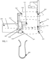
- Fig. 1 shows an exemplary lighting device 10 for a motor vehicle headlight, wherein the lighting device 10 comprises a circuit board 100 having a light source 110 which is connected to the circuit board 100 and is configured to emit light in a main emission direction X , and a light guide 200 , wherein the light guide 200 has an end designed as a light coupling surface 210 .
- main radiation direction is understood to mean the direction in which the light source 110, in this case an LED, emits the strongest or most light due to its directivity.
- the light guide 200 is assigned to guide light from the light source 110, which in this example is designed as an LED, which light can be coupled into the light guide 200 at the light coupling surface 210 .
- the light guide 200 can be brought into an end position P1 on the circuit board 100 , in which end position P1 the light coupling surface 210 is oriented in a fixed orientation orthogonal to the main emission direction X and at a fixed distance d along the main emission direction X with respect to the light source 110 .
- Fig. 1 shows the lighting device 10 in a not yet assembled state or not in the end position of the light guide 200 on the circuit board 100.
- the lighting device 10 further comprises a positioning device 300 which is designed to determine the alignment of the light coupling surface 210 with respect to the light source 110 along the main emission direction X of the light source 110 and in a normal plane of the main emission direction X , wherein the positioning device 300 for aligning the light coupling surface 210 in the normal plane has two first positioning means pairs 310 , each of which comprises a projection 311 which extends parallel to the main emission direction X , and an opening 312 corresponding to the projection 311 , wherein in Fig. 1 Due to the side view shown, only a first positioning pair is visible.
- Fig. 5 shows the two first positioning pairs 310 comprised by the lighting device 10 .
- the positioning device 300 comprises two second pairs of positioning means 320, each of which comprises a stop 321 and a stop surface 322 corresponding to the stop 321 .
- the light guide 200 comprises the projections 311 of the two first positioning means pairs 310 and the stops 321 of the two second Positioning means pairs 320, wherein the circuit board 100 has the remaining means of the two first positioning means pairs 310 and the two second positioning means pairs 320.
- the means of the first positioning pairs 310 are manufactured in one piece with the light guide 200 , for example by means of an injection molding process.
- the light guide 200 can be brought into the end position P1 on the circuit board 100 with respect to the at least one light source 110 , wherein the stops 321 of the second positioning means pairs 320 strike the corresponding stop surfaces 322 when the end position P1 is reached, as shown in Fig. 2 is shown.
- the projections 311 engage in a form-fitting manner in corresponding openings 312 and completely penetrate the circuit board 100 in the end position P1 .
- the lighting device comprises a securing means 400, which in the example shown is designed as a clamping means or clamp, wherein the securing means 400 is detachably arranged on the light guide 200 and the circuit board 100 , and wherein the securing means 400 is designed to secure the light guide 200 in the end position P1 on the circuit board 100 and to hold the light coupling surface 210 in position with respect to the light source 110 , as in Fig. 3 is shown, where Fig. 3 shows, among other things, an assembled state of the lighting device 10 .
- the clamping force caused by the clamping means 400 which presses the circuit board 100 and the light guide 200 against each other, must be greater than the force caused by an expansion of the material of the light guide 200 and the circuit board 100 , caused by an increase in temperature of the components mentioned, for example by the operation of the light source 110.
- Fig. 4 and Fig. 5 each show perspective views of the mounted lighting device 10.
- lighting device 10 circuit board 100 light source 110 light guide 200 End 201 light coupling surface 210 positioning device 300 First pair of positioning devices 310 projection 311 opening 312 Second pair of positioning devices 320 stop 321 stop surface 322 main radiation direction X end position P1 Distance d
Landscapes
- Engineering & Computer Science (AREA)
- General Engineering & Computer Science (AREA)
- Physics & Mathematics (AREA)
- Microelectronics & Electronic Packaging (AREA)
- Optics & Photonics (AREA)
- Mechanical Engineering (AREA)
- Non-Portable Lighting Devices Or Systems Thereof (AREA)
- Planar Illumination Modules (AREA)
- Fastening Of Light Sources Or Lamp Holders (AREA)
- Lighting Device Outwards From Vehicle And Optical Signal (AREA)
Description
- Die Erfindung betrifft eine Beleuchtungsvorrichtung für einen Kraftfahrzeugscheinwerfer., wobei die Beleuchtungsvorrichtung Folgendes umfasst:
- eine Leiterplatte, aufweisend zumindest eine Lichtquelle, welche mit der Leiterplatte verbunden ist und eingerichtet ist, Licht in eine Hauptabstrahlrichtung zu emittieren,
- einen Lichtleiter, aufweisend ein Ende, welches als Lichteinkoppelfläche ausgebildet ist, wobei der Lichtleiter zum Leiten von Licht der zumindest einen Lichtquelle zugeordnet ist, welches Licht an der Lichteinkoppelfläche in den Lichtleiter einkoppelbar ist, wobei der Lichtleiter in eine Endlage an der Leiterplatte bringbar ist, in welcher Endlage die Lichteinkoppelfläche in einer festgelegten Ausrichtung orthogonal zur Hauptabstrahlrichtung und in einem festgelegten Abstand entlang der Hauptabstrahlrichtung bezüglich der Lichtquelle orientiert ist,
- eine Positioniereinrichtung, welche eingerichtet ist, die Ausrichtung der Lichteinkoppelfläche bezüglich der Lichtquelle entlang der Hauptabstrahlrichtung der Lichtquelle sowie in einer Normalebene der Hauptabstrahlrichtung festzulegen, wobei die Positioniereinrichtung zur Ausrichtung der Lichteinkoppelfläche in der Normalebene zumindest ein erstes Positionierungsmittelpaar aufweist, welches einen Vorsprung, welcher sich parallel zur Hauptabstrahlrichtung erstreckt, und eine zu dem Vorsprung korrespondierende Öffnung umfasst, und wobei
- die Positioniereinrichtung zur Ausrichtung der Lichteinkoppelfläche entlang der Hauptabstrahlrichtung der Lichtquelle zumindest ein zweites Positionierungsmittelpaar aufweist, welches einen Anschlag und eine zu dem Anschlag korrespondierende Anschlagsfläche umfasst, wobei der Lichtleiter jeweils ein Mittel des zumindest einen ersten Positionierungsmittelpaares und des zumindest einen zweiten Positionierungsmittelpaares aufweist und die Leiterplatte jeweils das verbleibende Mittel des zumindest einen ersten Positionierungsmittelpaares und des zumindest einen zweiten Positionierungsmittelpaares aufweist, und wobei
- der Lichtleiter durch Einführen des Vorsprung des zumindest einen ersten Positionierungsmittelpaares in die dazu korrespondierende Öffnung des zumindest einen ersten Positionierungsmittelpaares in die Endlage an der Leiterplatte bezüglich der zumindest einen Lichtquelle bringbar ist, wobei der eine Anschlag des zumindest einen zweiten Positionierungsmittelpaares bei Erreichen der Endlage an der dazu korrespondierenden Anschlagsfläche des zumindest einen zweiten Positionierungsmittelpaares anschlägt, und
- ein Sicherungsmittel, welches eingerichtet ist, den Lichtleiter in der Endlage an der Leiterplatte zu sichern und die Lichteinkoppelfläche in Bezug auf die Lichtquelle in Position zu halten.
- Ferner betrifft die Erfindung einen Kraftfahrzeugscheinwerfer, umfassend zumindest eine erfindungsgemäße Beleuchtungsvorrichtung.
- Die
EP 2 775 197 A1 offenbart eine Beleuchtungsvorrichtung für Kraftfahrzeugscheinwerfer aus dem Stand der Technik. - In herkömmlichen Beleuchtungsvorrichtungen wird der Lichtleiter, dessen Lichteinkoppelfläche bezüglich einer Lichtquelle, welche auf einer Leiterplatte angeordnet ist, ausgerichtet ist, nicht direkt auf der Leiterplatte selbst befestigt.
- Aufgrund von steigenden Temperaturen beim Betrieb der Lichtquelle, dehnen sich die Materialien der Leiterplatte und des Lichtleiters bzw. der Lichteinkoppelfläche, welche sich in der Regel in nächster Nähe zur Lichtquelle befindet, aufgrund einer Wärmedehnung aus.
- Dadurch verändert sich jedoch der Abstand zwischen der Lichteinkoppelfläche des Lichtleiters und der zugeordneten Lichtquelle, was unterschiedliche lichttechnische Ergebnisse hervorruft, beispielsweise auch eine Zerstörung der Lichtquelle.
- Es ist eine Aufgabe der Erfindung eine verbesserte Beleuchtungsvorrichtung bereitzustellen.
- Diese Aufgabe wird mit einer eingangs erwähnten Beleuchtungsvorrichtung dadurch gelöst, dass das Sicherungsmittel als eine federelastische U-förmige Klemme ausgebildet ist, wobei die Klemme lösbar an dem Lichtleiter und der Leiterplatte angeordnet ist und dabei den Lichtleiter und die Leiterplatte umgreift und gegeneinander drückt.
- Durch die direkte Befestigung des Lichtleiters an der Leiterplatte bleibt der Abstand zwischen der Lichtquelle und der Lichteinkoppelfläche des Lichtleiters konstant. Somit wird die Ausdehnung des Gesamtsystems kompensiert.
- Unter "Hauptabstrahlrichtung" ist die Richtung zu verstehen, in der die zumindest eine Lichtquelle infolge ihrer Richtwirkung am stärksten bzw. am meisten Licht abstrahlt.
- Vorzugsweise liegt die Lichteinkoppelfläche des Lichtleiters in einer Normalebene zur Hauptabstrahlrichtung.
- Es kann vorgesehen sein, dass das entsprechende Mittel des zumindest einen ersten Positionierungsmittelpaares, welches Mittel an dem Lichtleiter angeordnet ist, einstückig mit dem Lichtleiter hergestellt ist.
- Beispielsweise wird der Lichtleiter mittels einem Spritzgießverfahren hergestellt.
- Es kann vorgesehen sein, dass das entsprechende Mittel des zumindest einen zweiten Positionierungsmittelpaares, welches Mittel an dem Lichtleiter angeordnet ist, einstückig mit dem Lichtleiter hergestellt ist.
- Es kann vorgesehen sein, dass die Positionierungseinrichtung zumindest zwei, vorzugsweise genau zwei, erste Positionierungsmittelpaare aufweist.
- Dadurch wird eine genauere Lage in einer Normalebene zur Hauptabstrahlrichtung der Lichtquelle festgelegt. Beispielsweise können die Vorsprünge als zylindrische Stifte ausgebildet sein, wobei bei Vorhandensein eines einziges solchen Stiftes - eingesetzt in der dafür vorgesehenen Öffnung - die Leiterplatte bzw. der Lichtleiter weiterhin verdrehbar um den zylindrischen Stift ist, was nicht erwünscht ist.
- Es kann vorgesehen sein, dass der Vorsprung des zumindest einen ersten Positionierungsmittelpaares an dem Lichtleiter und die Öffnung des zumindest einen ersten Positionierungsmittelpaares an der Leiterplatte angeordnet ist.
- Dadurch wird eine schraubenlose Befestigung des Lichtleiters an der Leiterplatte erzielt. Somit macht die Leiterplatte die thermische Ausdehnung mit und der Abstand der Lichtquelle zur Lichteinkoppelfläche kann konstant gehalten werden.
- Die von dem Klemmmittel verursachte Klemmkraft, welche die Leiterplatte und den Lichtleiter gegeneinander drückt, muss größer sein als die Kraft, welche durch eine Ausdehnung des Materials des Lichtleiters und der Leiterplatte entsteht, hervorgerufen durch eine Temperaturerhöhung, beispielsweise durch den Betrieb der Lichtquelle, der genannten Komponenten.
- Es kann vorgesehen sein, dass die Positionierungseinrichtung zumindest zwei, vorzugsweise genau zwei, zweite Positionierungsmittelpaare aufweist.
- Es kann vorgesehen sein, dass der Anschlag des zweiten Positionierungsmittelpaares an dem Lichtleiter und die Anschlagsfläche des zweiten Positionierungsmittelpaares an der Leiterplatte angeordnet ist.
- Es kann vorgesehen sein, dass der Vorsprung formschlüssig in die dazu korrespondierende Öffnung eingreift.
- Es kann vorgesehen sein, dass der Vorsprung die Leiterplatte in der Endlage des Lichtleiters an der Leiterplatte durchsetzt.
- Es kann vorgesehen sein, dass die zumindest eine Lichtquelle als LED ausgebildet ist.
- Vorzugsweise ist vorgesehen, dass im Fall, dass zwei oder mehr Leuchtdioden (LED) vorgesehen sind, jede Leuchtdiode unabhängig von den anderen Leuchtdioden angesteuert werden kann.
- Jede Leuchtdiode kann somit unabhängig von den anderen Leuchtdioden einer Lichtquelle ein- und ausgeschaltet werden, und vorzugsweise, wenn es sich um dimmbare
- Leuchtdioden handelt, auch unabhängig von den anderen Leuchtdioden der Lichtquelle gedimmt werden.
- Die Aufgabe wird ebenso mit einem Kraftfahrzeugscheinwerfer gelöst, welcher zumindest eine erfindungsgemäße Beleuchtungsvorrichtung umfasst.
- Nachfolgend wird die Erfindung anhand von beispielhaften Zeichnungen näher erläutert. Hierbei zeigt
-
Fig. 1 eine beispielhafte Beleuchtungsvorrichtung in einer Seitansicht mit einem Lichtleiter, welche ein als Lichteinkoppelfläche ausgebildetes Ende aufweist, und einer Leiterplatte, auf welcher eine Lichtquelle angeordnet ist, in einem nicht montierten Zustand der Beleuchtungsvorrichtung, -
Fig. 2 die Beleuchtungsvorrichtung ausFig. 1 , wobei sich der Lichtleiter in einer Endlage an der Leiterplatte befindet, -
Fig. 3 die Beleuchtungsvorrichtung ausFig. 2 , wobei sich der in der Endlage an der Leiterplatte befindende Lichtleiter und die Leiterplatte mittels eines Sicherungsmittels, welches als Klemmmittel bzw. Klemme ausgebildet ist, gesichert sind, -
Fig. 4 eine perspektivische Ansicht der zusammengebauten Beleuchtungsvorrichtung ausFig. 1 , und -
Fig. 5 eine weitere perspektivische Rückansicht der zusammengebauten Beleuchtungsvorrichtung ausFig. 1 . -
Fig. 1 zeigt eine beispielhafte Beleuchtungsvorrichtung 10 für einen Kraftfahrzeugscheinwerfer, wobei die Beleuchtungsvorrichtung 10 eine Leiterplatte 100, aufweisend eine Lichtquelle 110, welche mit der Leiterplatte 100 verbunden ist und eingerichtet ist, Licht in eine Hauptabstrahlrichtung X zu emittieren, und einen Lichtleiter 200 umfasst, wobei der Lichtleiter 200 ein als Lichteinkoppelfläche 210 ausgebildetes Ende aufweist. - Unter "Hauptabstrahlrichtung" ist die Richtung zu verstehen, in der die Lichtquelle 110, in diesem Fall eine LED, infolge ihrer Richtwirkung am stärksten bzw. am meisten Licht abstrahlt.
- Der Lichtleiter 200 ist zum Leiten von Licht der Lichtquelle 110, welche in diesem Beispiel als LED ausgebildet ist, zugeordnet, welches Licht an der Lichteinkoppelfläche 210 in den Lichtleiter 200 einkoppelbar ist.
- Ferner ist der Lichtleiter 200 in eine Endlage P1 an der Leiterplatte 100 bringbar, in welcher Endlage P1 die Lichteinkoppelfläche 210 in einer festgelegten Ausrichtung orthogonal zur Hauptabstrahlrichtung X und in einem festgelegten Abstand d entlang der Hauptabstrahlrichtung X bezüglich der Lichtquelle 110 orientiert ist.
-
Fig. 1 zeigt hierzu die Beleuchtungsvorrichtung 10 in einem noch nicht montierten Zustand bzw. nicht in der Endlage des Lichtleiters 200 an der Leiterplatte 100. - Die Beleuchtungsvorrichtung 10 umfasst weiters eine Positioniereinrichtung 300, welche eingerichtet ist, die Ausrichtung der Lichteinkoppelfläche 210 bezüglich der Lichtquelle 110 entlang der Hauptabstrahlrichtung X der Lichtquelle 110 sowie in einer Normalebene der Hauptabstrahlrichtung X festzulegen, wobei die Positioniereinrichtung 300 zur Ausrichtung der Lichteinkoppelfläche 210 in der Normalebene zwei erste Positionierungsmittelpaare 310 aufweist, welche jeweils einen Vorsprung 311, welcher sich parallel zur Hauptabstrahlrichtung X erstreckt, und eine zu dem Vorsprung 311 korrespondierende Öffnung 312 umfassen, wobei in
Fig. 1 aufgrund der dargestellten Seitenansicht lediglich nur ein erstes Positionierungspaar sichtbar ist.Fig. 5 zeigt die zwei von der Beleuchtungsvorrichtung 10 umfassten zwei erste Positionierungspaare 310. - Zur Ausrichtung der Lichteinkoppelfläche 210 entlang der Hauptabstrahlrichtung X der Lichtquelle 110 umfasst die Positioniereinrichtung 300 zwei zweite Positionierungsmittelpaare 320, welche jeweils einen Anschlag 321 und eine zu dem Anschlag 321 korrespondierende Anschlagsfläche 322 umfassen.
- In dem gezeigten Beispiel umfasst der Lichtleiter 200 die Vorsprünge 311 der zwei ersten Positionierungsmittelpaare 310 und die Anschläge 321 der zwei zweiten Positionierungsmittelpaare 320, wobei die Leiterplatte 100 die jeweils verbleibenden Mittel der zwei ersten Positionierungsmittelpaare 310 und der zwei zweiten Positionierungsmittelpaare 320 aufweist. Die Mittel der ersten Positionierungspaare 310 sind hierbei einstückig mit dem Lichtleiter 200 hergestellt, beispielsweise mittels einem Spritzgießverfahren.
- Durch Einführen der Vorsprünge 311 der ersten Positionierungsmittelpaare 310 in die dazu korrespondierenden Öffnung 312 ist der Lichtleiter 200 in die Endlage P1 an der Leiterplatte 100 bezüglich der zumindest einen Lichtquelle 110 bringbar, wobei die Anschläge 321 der zweiten Positionierungsmittelpaare 320 bei Erreichen der Endlage P1 an den dazu korrespondierenden Anschlagsflächen 322 anschlagen, wie in
Fig. 2 gezeigt ist. Dabei greifen die Vorsprünge 311 formschlüssig in korrespondierenden Öffnungen 312 ein und durchsetzen in der Endlage P1 die Leiterplatte 100 vollständig. - Weiters umfasst die Beleuchtungsvorrichtung ein Sicherungsmittel 400, welches in dem gezeigten Beispiel als Klemmmittel bzw. Klemme ausgebildet ist, wobei das Sicherungsmittel 400 lösbar an dem Lichtleiter 200 und der Leiterplatte 100 angeordnet ist, und wobei das Sicherungsmittel 400 eingerichtet ist, den Lichtleiter 200 in der Endlage P1 an der Leiterplatte 100 zu sichern und die Lichteinkoppelfläche 210 in Bezug auf die Lichtquelle 110 in Position zu halten, wie in
Fig. 3 dargestellt ist, wobeiFig. 3 unter anderem einen montierten Zustand der Beleuchtungsvorrichtung 10 zeigt. - Hierbei ist darauf zu achten, dass die von dem Klemmmittel 400 verursachte Klemmkraft, welche die Leiterplatte 100 und den Lichtleiter 200 gegeneinander drückt, muss größer sein als die Kraft, welche durch eine Ausdehnung des Materials des Lichtleiters 200 und der Leiterplatte 100 entsteht, hervorgerufen durch eine Temperaturerhöhung der genannten Komponenten, beispielsweise durch den Betrieb der Lichtquelle 110.
-
Fig. 4 undFig. 5 zeigen jeweils perspektivische Ansichten der montierten Beleuchtungsvorrichtung 10. -
Beleuchtungsvorrichtung 10 Leiterplatte 100 Lichtquelle 110 Lichtleiter 200 Ende 201 Lichteinkoppelfläche 210 Positioniereinrichtung 300 Erstes Positionierungsmittelpaar 310 Vorsprung 311 Öffnung 312 Zweites Positionierungsmittelpaar 320 Anschlag 321 Anschlagsfläche 322 Hauptabstrahlrichtung X Endlage P1 Abstand d
Claims (11)
- Beleuchtungsvorrichtung (10) für einen Kraftfahrzeugscheinwerfer, wobei die Beleuchtungsvorrichtung (10) Folgendes umfasst:- eine Leiterplatte (100), aufweisend zumindest eine Lichtquelle (110), welche mit der Leiterplatte (100) verbunden ist und eingerichtet ist, Licht in eine Hauptabstrahlrichtung (X) zu emittieren,- einen Lichtleiter (200), aufweisend ein Ende (201), welches als Lichteinkoppelfläche (210) ausgebildet ist, wobei der Lichtleiter (200) zum Leiten von Licht der zumindest einen Lichtquelle (110) zugeordnet ist, welches Licht an der Lichteinkoppelfläche (210) in den Lichtleiter (200) einkoppelbar ist, wobei der Lichtleiter (200) in eine Endlage (P1) an der Leiterplatte (100) bringbar ist, in welcher Endlage (P1) die Lichteinkoppelfläche (210) in einer festgelegten Ausrichtung orthogonal zur Hauptabstrahlrichtung (X) und in einem festgelegten Abstand (d) entlang der Hauptabstrahlrichtung (X) bezüglich der Lichtquelle (110) orientiert ist,- eine Positioniereinrichtung (300), welche eingerichtet ist, die Ausrichtung der Lichteinkoppelfläche (210) bezüglich der Lichtquelle (110) entlang der Hauptabstrahlrichtung (X) der Lichtquelle (110) sowie in einer Normalebene der Hauptabstrahlrichtung (X) festzulegen, wobei die Positioniereinrichtung (300) zur Ausrichtung der Lichteinkoppelfläche (210) in der Normalebene zumindest ein erstes Positionierungsmittelpaar (310) aufweist, welches einen Vorsprung (311), welcher sich parallel zur Hauptabstrahlrichtung (X) erstreckt, und eine zu dem Vorsprung (311) korrespondierende Öffnung (312) umfasst, und wobeidie Positioniereinrichtung (300) zur Ausrichtung der Lichteinkoppelfläche (210) entlang der Hauptabstrahlrichtung (X) der Lichtquelle (110) zumindest ein zweites Positionierungsmittelpaar (320) aufweist, welches einen Anschlag (321) und eine zu dem Anschlag (321) korrespondierende Anschlagsfläche (322) umfasst, wobei der Lichtleiter (200) jeweils ein Mittel des zumindest einen ersten Positionierungsmittelpaares (310) und des zumindest einen zweiten Positionierungsmittelpaares (320) aufweist und die Leiterplatte (100) jeweils das verbleibende Mittel des zumindest einen ersten Positionierungsmittelpaares (310) und des zumindest einen zweiten Positionierungsmittelpaares (320) aufweist, und wobeider Lichtleiter (200) durch Einführen des Vorsprungs (311) des zumindest einen ersten Positionierungsmittelpaares (310) in die dazu korrespondierende Öffnung (312) des zumindest einen ersten Positionierungsmittelpaares (310) in die Endlage (P1) an der Leiterplatte (100) bezüglich der zumindest einen Lichtquelle (110) bringbar ist, wobei der eine Anschlag (321) des zumindest einen zweiten Positionierungsmittelpaares (320) bei Erreichen der Endlage (P1) an der dazu korrespondierenden Anschlagsfläche (322) des zumindest einen zweiten Positionierungsmittelpaares (320) anschlägt, und- ein Sicherungsmittel (400), welches eingerichtet ist, den Lichtleiter (200) in der Endlage (P1) an der Leiterplatte (100) zu sichern und die Lichteinkoppelfläche (210) in Bezug auf die Lichtquelle (110) in Position zu halten,dadurch gekennzeichnet, dass
das Sicherungsmittel (400) als eine federelastische U-förmige Klemme ausgebildet ist, wobei die Klemme lösbar an dem Lichtleiter (200) und der Leiterplatte (100) angeordnet ist und dabei den Lichtleiter (200) und die Leiterplatte (100) umgreift und gegeneinander drückt. - Beleuchtungsvorrichtung nach Anspruch 1, dadurch gekennzeichnet, dass das entsprechende Mittel des zumindest einen ersten Positionierungsmittelpaares (310), welches Mittel an dem Lichtleiter (200) angeordnet ist, einstückig mit dem Lichtleiter (200) hergestellt ist.
- Beleuchtungsvorrichtung nach Anspruch 1 oder 2, dadurch gekennzeichnet, dass das entsprechende Mittel des zumindest einen zweiten Positionierungsmittelpaares (320), welches Mittel an dem Lichtleiter (200) angeordnet ist, einstückig mit dem Lichtleiter (200) hergestellt ist.
- Beleuchtungsvorrichtung nach einem der Ansprüche 1 bis 3, dadurch gekennzeichnet, dass die Positioniereinrichtung (300) zumindest zwei, vorzugsweise genau zwei, erste Positionierungsmittelpaare (310) aufweist.
- Beleuchtungsvorrichtung nach einem der Ansprüche 1 bis 4, dadurch gekennzeichnet, dass der Vorsprung (311) des zumindest einen ersten Positionierungsmittelpaares (310) an dem Lichtleiter (200) und die Öffnung (312) des zumindest einen ersten Positionierungsmittelpaares (310) an der Leiterplatte (100) angeordnet ist.
- Beleuchtungsvorrichtung nach einem der Ansprüche 1 bis 5, dadurch gekennzeichnet, dass die Positioniereinrichtung (300) zumindest zwei, vorzugsweise genau zwei, zweite Positionierungsmittelpaare (320) aufweist.
- Beleuchtungsvorrichtung nach einem der Ansprüche 1 bis 6, dadurch gekennzeichnet, dass der Anschlag (321) des zumindest einen zweiten Positionierungsmittelpaares (320) an dem Lichtleiter (200) und die Anschlagsfläche (322) des zumindest einen zweiten Positionierungsmittelpaares (320) an der Leiterplatte (100) angeordnet ist.
- Beleuchtungsvorrichtung nach einem der Ansprüche 1 bis 7, dadurch gekennzeichnet, dass der Vorsprung (311) formschlüssig in die dazu korrespondierende Öffnung (312) eingreift.
- Beleuchtungsvorrichtung nach einem der Ansprüche 1 bis 8, dadurch gekennzeichnet, dass der Vorsprung (311) die Leiterplatte (100) in der Endlage (P1) des Lichtleiters (200) an der Leiterplatte (100) durchsetzt.
- Beleuchtungsvorrichtung nach einem der Ansprüche 1 bis 9, dadurch gekennzeichnet, dass die zumindest eine Lichtquelle (110) als LED ausgebildet ist.
- Kraftfahrzeugscheinwerfer, umfassend zumindest eine Beleuchtungsvorrichtung (10) gemäß einem der Ansprüche 1 bis 10.
Priority Applications (3)
| Application Number | Priority Date | Filing Date | Title |
|---|---|---|---|
| EP19177334.0A EP3745017B1 (de) | 2019-05-29 | 2019-05-29 | Beleuchtungsvorrichtung für einen kraftfahrzeugscheinwerfer |
| KR1020200059503A KR20200138660A (ko) | 2019-05-29 | 2020-05-19 | 자동차 헤드램프용 조명 장치 |
| CN202010473339.9A CN112013347A (zh) | 2019-05-29 | 2020-05-29 | 用于机动车前照灯的照明装置 |
Applications Claiming Priority (1)
| Application Number | Priority Date | Filing Date | Title |
|---|---|---|---|
| EP19177334.0A EP3745017B1 (de) | 2019-05-29 | 2019-05-29 | Beleuchtungsvorrichtung für einen kraftfahrzeugscheinwerfer |
Publications (2)
| Publication Number | Publication Date |
|---|---|
| EP3745017A1 EP3745017A1 (de) | 2020-12-02 |
| EP3745017B1 true EP3745017B1 (de) | 2024-12-04 |
Family
ID=66676402
Family Applications (1)
| Application Number | Title | Priority Date | Filing Date |
|---|---|---|---|
| EP19177334.0A Active EP3745017B1 (de) | 2019-05-29 | 2019-05-29 | Beleuchtungsvorrichtung für einen kraftfahrzeugscheinwerfer |
Country Status (3)
| Country | Link |
|---|---|
| EP (1) | EP3745017B1 (de) |
| KR (1) | KR20200138660A (de) |
| CN (1) | CN112013347A (de) |
Families Citing this family (2)
| Publication number | Priority date | Publication date | Assignee | Title |
|---|---|---|---|---|
| DE102022109864B3 (de) * | 2022-04-25 | 2023-09-28 | HELLA GmbH & Co. KGaA | Scheinwerfer für ein Kraftfahrzeug |
| CN121548714A (zh) * | 2023-06-28 | 2026-02-17 | 亮锐新加坡私人有限公司 | 用于机动车发光二极管模块的光导保持器和参考系统 |
Family Cites Families (7)
| Publication number | Priority date | Publication date | Assignee | Title |
|---|---|---|---|---|
| JP4062703B2 (ja) * | 2004-04-28 | 2008-03-19 | スタンレー電気株式会社 | 照明ユニット |
| FR2972975B1 (fr) * | 2011-01-18 | 2014-08-22 | Valeo Vision | Unite optique pour dispositif de signalisation et/ou d'eclairage |
| FR3002794B1 (fr) * | 2013-03-04 | 2015-03-20 | Valeo Vision Belgique | Dispositif d'eclairage et/ou de signalisation pour vehicule automobile,comportant un guide de lumiere |
| AT516170B1 (de) * | 2014-09-16 | 2016-03-15 | Zizala Lichtsysteme Gmbh | Beleuchtungsvorrichtung mit darin verriegelbarer lichtleiteranordnung |
| FR3061562B1 (fr) * | 2017-01-04 | 2019-08-02 | Valeo Vision | Dispositif de raccordement amovible pour un guide de lumiere et application dans un vehicule automobile, module a transmission optique pourvu du dispositif |
| US10641473B2 (en) * | 2017-03-30 | 2020-05-05 | Valeo North America, Inc. | Folded heat sink with electrical connection protection |
| US10190745B2 (en) * | 2017-04-27 | 2019-01-29 | Valeo North America, Inc. | Lamp assembly for use in a headlamp |
-
2019
- 2019-05-29 EP EP19177334.0A patent/EP3745017B1/de active Active
-
2020
- 2020-05-19 KR KR1020200059503A patent/KR20200138660A/ko not_active Ceased
- 2020-05-29 CN CN202010473339.9A patent/CN112013347A/zh active Pending
Also Published As
| Publication number | Publication date |
|---|---|
| CN112013347A (zh) | 2020-12-01 |
| KR20200138660A (ko) | 2020-12-10 |
| EP3745017A1 (de) | 2020-12-02 |
Similar Documents
| Publication | Publication Date | Title |
|---|---|---|
| EP3004724B1 (de) | Beleuchtungsvorrichtung für einen fahrzeugscheinwerfer | |
| WO2014124477A1 (de) | Lichtmodul für einen fahrzeugscheinwerfer | |
| DE102012103439B9 (de) | Rastvorrichtung zum Verbinden von Bauteilen | |
| EP3745017B1 (de) | Beleuchtungsvorrichtung für einen kraftfahrzeugscheinwerfer | |
| DE102013108650A1 (de) | Befestigungssystem mit Exzenter | |
| EP2693108A1 (de) | Lichtmodul und Verfahren zur Herstellung eines Lichtmoduls | |
| EP2693109A2 (de) | Lichtmodul | |
| DE202010007364U1 (de) | Brennerwechselmodul, Schweißbrenner, Rohrbogen, Brennerhalterung, Schlauchpaket für einen Schweißbrenner, Aufnahmemodul und Brennerwechselsystem | |
| EP3359822B1 (de) | Befestigungselement | |
| DE102008013921B4 (de) | Anordnung zur justierbaren Befestigung zweier Körper zueinander | |
| WO2017009099A1 (de) | Modulartig aufgebaute led-strahlereinheit und verwendung derselben | |
| DE202015107015U1 (de) | Befestigungselement zur Anordnung einer Leiterplatte auf einem Leuchtenbauteil | |
| AT513339B1 (de) | Lichtmodul für ein Kraftfahrzeug sowie Kraftfahrzeugscheinwerfer | |
| WO2005027598A1 (de) | Flexible schaltungsträgeranordnung | |
| EP2428602B1 (de) | Legenadelanordnung für eine Jacquard-Legebarre und Jacquard-Legebarre | |
| EP3317581B1 (de) | Beleuchtungsvorrichtung für einen kraftfahrzeugscheinwerfer | |
| EP3894742B1 (de) | Beleuchtungsvorrichtung für einen kraftfahrzeugscheinwerfer | |
| EP4703635A1 (de) | Filter, scheinwerfer und system aus beiden | |
| EP3743240B1 (de) | Vorrichtung zum abbremsen und halten eines verarbeitungselements | |
| DE102016201382B3 (de) | Leuchtenanordnung für ein Kraftfahrzeug und Heckspoiler | |
| DE60002670T2 (de) | Lampenadapter mit integriertem elektronischen vorschaltgerät zur aufnahme von hochleistunsleuchtstofflampen, zum ersetzen von leuchtstofflampen mit einem induktiven vorschaltgerät | |
| DE102017106635B4 (de) | Verfahren zur Verbindung von drei Bauteilen und verbundenes System | |
| DE102020105708B4 (de) | Gargeräteleuchte mit formschlüssig gehaltenem Lichtleitstab und Verfahren zur Montage eines Lichtleitstabes | |
| DE102013217952B3 (de) | Vorrichtung zur Zuführung eines Heißgasstroms | |
| DE102004052348B4 (de) | Kraftfahrzeugleuchte |
Legal Events
| Date | Code | Title | Description |
|---|---|---|---|
| PUAI | Public reference made under article 153(3) epc to a published international application that has entered the european phase |
Free format text: ORIGINAL CODE: 0009012 |
|
| STAA | Information on the status of an ep patent application or granted ep patent |
Free format text: STATUS: THE APPLICATION HAS BEEN PUBLISHED |
|
| AK | Designated contracting states |
Kind code of ref document: A1 Designated state(s): AL AT BE BG CH CY CZ DE DK EE ES FI FR GB GR HR HU IE IS IT LI LT LU LV MC MK MT NL NO PL PT RO RS SE SI SK SM TR |
|
| AX | Request for extension of the european patent |
Extension state: BA ME |
|
| STAA | Information on the status of an ep patent application or granted ep patent |
Free format text: STATUS: REQUEST FOR EXAMINATION WAS MADE |
|
| 17P | Request for examination filed |
Effective date: 20210519 |
|
| RBV | Designated contracting states (corrected) |
Designated state(s): AL AT BE BG CH CY CZ DE DK EE ES FI FR GB GR HR HU IE IS IT LI LT LU LV MC MK MT NL NO PL PT RO RS SE SI SK SM TR |
|
| STAA | Information on the status of an ep patent application or granted ep patent |
Free format text: STATUS: EXAMINATION IS IN PROGRESS |
|
| 17Q | First examination report despatched |
Effective date: 20220831 |
|
| GRAP | Despatch of communication of intention to grant a patent |
Free format text: ORIGINAL CODE: EPIDOSNIGR1 |
|
| STAA | Information on the status of an ep patent application or granted ep patent |
Free format text: STATUS: GRANT OF PATENT IS INTENDED |
|
| GRAS | Grant fee paid |
Free format text: ORIGINAL CODE: EPIDOSNIGR3 |
|
| GRAA | (expected) grant |
Free format text: ORIGINAL CODE: 0009210 |
|
| STAA | Information on the status of an ep patent application or granted ep patent |
Free format text: STATUS: THE PATENT HAS BEEN GRANTED |
|
| INTG | Intention to grant announced |
Effective date: 20241016 |
|
| AK | Designated contracting states |
Kind code of ref document: B1 Designated state(s): AL AT BE BG CH CY CZ DE DK EE ES FI FR GB GR HR HU IE IS IT LI LT LU LV MC MK MT NL NO PL PT RO RS SE SI SK SM TR |
|
| REG | Reference to a national code |
Ref country code: GB Ref legal event code: FG4D Free format text: NOT ENGLISH |
|
| REG | Reference to a national code |
Ref country code: CH Ref legal event code: EP |
|
| REG | Reference to a national code |
Ref country code: DE Ref legal event code: R096 Ref document number: 502019012581 Country of ref document: DE |
|
| REG | Reference to a national code |
Ref country code: IE Ref legal event code: FG4D Free format text: LANGUAGE OF EP DOCUMENT: GERMAN |
|
| P01 | Opt-out of the competence of the unified patent court (upc) registered |
Free format text: CASE NUMBER: APP_5241/2025 Effective date: 20250131 |
|
| REG | Reference to a national code |
Ref country code: LT Ref legal event code: MG9D |
|
| REG | Reference to a national code |
Ref country code: NL Ref legal event code: MP Effective date: 20241204 |
|
| PG25 | Lapsed in a contracting state [announced via postgrant information from national office to epo] |
Ref country code: HR Free format text: LAPSE BECAUSE OF FAILURE TO SUBMIT A TRANSLATION OF THE DESCRIPTION OR TO PAY THE FEE WITHIN THE PRESCRIBED TIME-LIMIT Effective date: 20241204 |
|
| PG25 | Lapsed in a contracting state [announced via postgrant information from national office to epo] |
Ref country code: FI Free format text: LAPSE BECAUSE OF FAILURE TO SUBMIT A TRANSLATION OF THE DESCRIPTION OR TO PAY THE FEE WITHIN THE PRESCRIBED TIME-LIMIT Effective date: 20241204 |
|
| PG25 | Lapsed in a contracting state [announced via postgrant information from national office to epo] |
Ref country code: BG Free format text: LAPSE BECAUSE OF FAILURE TO SUBMIT A TRANSLATION OF THE DESCRIPTION OR TO PAY THE FEE WITHIN THE PRESCRIBED TIME-LIMIT Effective date: 20241204 |
|
| PG25 | Lapsed in a contracting state [announced via postgrant information from national office to epo] |
Ref country code: ES Free format text: LAPSE BECAUSE OF FAILURE TO SUBMIT A TRANSLATION OF THE DESCRIPTION OR TO PAY THE FEE WITHIN THE PRESCRIBED TIME-LIMIT Effective date: 20241204 |
|
| PG25 | Lapsed in a contracting state [announced via postgrant information from national office to epo] |
Ref country code: NO Free format text: LAPSE BECAUSE OF FAILURE TO SUBMIT A TRANSLATION OF THE DESCRIPTION OR TO PAY THE FEE WITHIN THE PRESCRIBED TIME-LIMIT Effective date: 20250304 |
|
| PG25 | Lapsed in a contracting state [announced via postgrant information from national office to epo] |
Ref country code: LV Free format text: LAPSE BECAUSE OF FAILURE TO SUBMIT A TRANSLATION OF THE DESCRIPTION OR TO PAY THE FEE WITHIN THE PRESCRIBED TIME-LIMIT Effective date: 20241204 Ref country code: GR Free format text: LAPSE BECAUSE OF FAILURE TO SUBMIT A TRANSLATION OF THE DESCRIPTION OR TO PAY THE FEE WITHIN THE PRESCRIBED TIME-LIMIT Effective date: 20250305 |
|
| PG25 | Lapsed in a contracting state [announced via postgrant information from national office to epo] |
Ref country code: RS Free format text: LAPSE BECAUSE OF FAILURE TO SUBMIT A TRANSLATION OF THE DESCRIPTION OR TO PAY THE FEE WITHIN THE PRESCRIBED TIME-LIMIT Effective date: 20250304 |
|
| PG25 | Lapsed in a contracting state [announced via postgrant information from national office to epo] |
Ref country code: NL Free format text: LAPSE BECAUSE OF FAILURE TO SUBMIT A TRANSLATION OF THE DESCRIPTION OR TO PAY THE FEE WITHIN THE PRESCRIBED TIME-LIMIT Effective date: 20241204 |
|
| PG25 | Lapsed in a contracting state [announced via postgrant information from national office to epo] |
Ref country code: SM Free format text: LAPSE BECAUSE OF FAILURE TO SUBMIT A TRANSLATION OF THE DESCRIPTION OR TO PAY THE FEE WITHIN THE PRESCRIBED TIME-LIMIT Effective date: 20241204 |
|
| PG25 | Lapsed in a contracting state [announced via postgrant information from national office to epo] |
Ref country code: PL Free format text: LAPSE BECAUSE OF FAILURE TO SUBMIT A TRANSLATION OF THE DESCRIPTION OR TO PAY THE FEE WITHIN THE PRESCRIBED TIME-LIMIT Effective date: 20241204 |
|
| PGFP | Annual fee paid to national office [announced via postgrant information from national office to epo] |
Ref country code: DE Payment date: 20250521 Year of fee payment: 7 |
|
| PG25 | Lapsed in a contracting state [announced via postgrant information from national office to epo] |
Ref country code: IS Free format text: LAPSE BECAUSE OF FAILURE TO SUBMIT A TRANSLATION OF THE DESCRIPTION OR TO PAY THE FEE WITHIN THE PRESCRIBED TIME-LIMIT Effective date: 20250404 |
|
| PG25 | Lapsed in a contracting state [announced via postgrant information from national office to epo] |
Ref country code: PT Free format text: LAPSE BECAUSE OF FAILURE TO SUBMIT A TRANSLATION OF THE DESCRIPTION OR TO PAY THE FEE WITHIN THE PRESCRIBED TIME-LIMIT Effective date: 20250404 |
|
| PG25 | Lapsed in a contracting state [announced via postgrant information from national office to epo] |
Ref country code: EE Free format text: LAPSE BECAUSE OF FAILURE TO SUBMIT A TRANSLATION OF THE DESCRIPTION OR TO PAY THE FEE WITHIN THE PRESCRIBED TIME-LIMIT Effective date: 20241204 |
|
| PGFP | Annual fee paid to national office [announced via postgrant information from national office to epo] |
Ref country code: FR Payment date: 20250528 Year of fee payment: 7 |
|
| PG25 | Lapsed in a contracting state [announced via postgrant information from national office to epo] |
Ref country code: RO Free format text: LAPSE BECAUSE OF FAILURE TO SUBMIT A TRANSLATION OF THE DESCRIPTION OR TO PAY THE FEE WITHIN THE PRESCRIBED TIME-LIMIT Effective date: 20241204 |
|
| PG25 | Lapsed in a contracting state [announced via postgrant information from national office to epo] |
Ref country code: SK Free format text: LAPSE BECAUSE OF FAILURE TO SUBMIT A TRANSLATION OF THE DESCRIPTION OR TO PAY THE FEE WITHIN THE PRESCRIBED TIME-LIMIT Effective date: 20241204 |
|
| PG25 | Lapsed in a contracting state [announced via postgrant information from national office to epo] |
Ref country code: CZ Free format text: LAPSE BECAUSE OF FAILURE TO SUBMIT A TRANSLATION OF THE DESCRIPTION OR TO PAY THE FEE WITHIN THE PRESCRIBED TIME-LIMIT Effective date: 20241204 |
|
| PG25 | Lapsed in a contracting state [announced via postgrant information from national office to epo] |
Ref country code: IT Free format text: LAPSE BECAUSE OF FAILURE TO SUBMIT A TRANSLATION OF THE DESCRIPTION OR TO PAY THE FEE WITHIN THE PRESCRIBED TIME-LIMIT Effective date: 20241204 |
|
| REG | Reference to a national code |
Ref country code: DE Ref legal event code: R097 Ref document number: 502019012581 Country of ref document: DE |
|
| PG25 | Lapsed in a contracting state [announced via postgrant information from national office to epo] |
Ref country code: SE Free format text: LAPSE BECAUSE OF FAILURE TO SUBMIT A TRANSLATION OF THE DESCRIPTION OR TO PAY THE FEE WITHIN THE PRESCRIBED TIME-LIMIT Effective date: 20241204 |
|
| PG25 | Lapsed in a contracting state [announced via postgrant information from national office to epo] |
Ref country code: DK Free format text: LAPSE BECAUSE OF FAILURE TO SUBMIT A TRANSLATION OF THE DESCRIPTION OR TO PAY THE FEE WITHIN THE PRESCRIBED TIME-LIMIT Effective date: 20241204 |
|
| PLBE | No opposition filed within time limit |
Free format text: ORIGINAL CODE: 0009261 |
|
| STAA | Information on the status of an ep patent application or granted ep patent |
Free format text: STATUS: NO OPPOSITION FILED WITHIN TIME LIMIT |
|
| REG | Reference to a national code |
Ref country code: CH Ref legal event code: L10 Free format text: ST27 STATUS EVENT CODE: U-0-0-L10-L00 (AS PROVIDED BY THE NATIONAL OFFICE) Effective date: 20251015 |
|
| 26N | No opposition filed |
Effective date: 20250905 |
|
| REG | Reference to a national code |
Ref country code: CH Ref legal event code: H13 Free format text: ST27 STATUS EVENT CODE: U-0-0-H10-H13 (AS PROVIDED BY THE NATIONAL OFFICE) Effective date: 20251223 |
|
| PG25 | Lapsed in a contracting state [announced via postgrant information from national office to epo] |
Ref country code: LU Free format text: LAPSE BECAUSE OF NON-PAYMENT OF DUE FEES Effective date: 20250529 |
|
| PG25 | Lapsed in a contracting state [announced via postgrant information from national office to epo] |
Ref country code: CH Free format text: LAPSE BECAUSE OF NON-PAYMENT OF DUE FEES Effective date: 20250531 |
|
| GBPC | Gb: european patent ceased through non-payment of renewal fee |
Effective date: 20250529 |
|
| REG | Reference to a national code |
Ref country code: BE Ref legal event code: MM Effective date: 20250531 |
|
| PG25 | Lapsed in a contracting state [announced via postgrant information from national office to epo] |
Ref country code: MC Free format text: LAPSE BECAUSE OF FAILURE TO SUBMIT A TRANSLATION OF THE DESCRIPTION OR TO PAY THE FEE WITHIN THE PRESCRIBED TIME-LIMIT Effective date: 20241204 |
|
| PG25 | Lapsed in a contracting state [announced via postgrant information from national office to epo] |
Ref country code: GB Free format text: LAPSE BECAUSE OF NON-PAYMENT OF DUE FEES Effective date: 20250529 |
|
| PG25 | Lapsed in a contracting state [announced via postgrant information from national office to epo] |
Ref country code: IE Free format text: LAPSE BECAUSE OF NON-PAYMENT OF DUE FEES Effective date: 20250529 |
|
| PG25 | Lapsed in a contracting state [announced via postgrant information from national office to epo] |
Ref country code: BE Free format text: LAPSE BECAUSE OF NON-PAYMENT OF DUE FEES Effective date: 20250531 |