EP3745039B1 - Rauchabzugsanlage - Google Patents
Rauchabzugsanlage Download PDFInfo
- Publication number
- EP3745039B1 EP3745039B1 EP20170274.3A EP20170274A EP3745039B1 EP 3745039 B1 EP3745039 B1 EP 3745039B1 EP 20170274 A EP20170274 A EP 20170274A EP 3745039 B1 EP3745039 B1 EP 3745039B1
- Authority
- EP
- European Patent Office
- Prior art keywords
- extraction
- air
- insufflation
- air extraction
- shutter
- Prior art date
- Legal status (The legal status is an assumption and is not a legal conclusion. Google has not performed a legal analysis and makes no representation as to the accuracy of the status listed.)
- Active
Links
Images



Classifications
-
- F—MECHANICAL ENGINEERING; LIGHTING; HEATING; WEAPONS; BLASTING
- F24—HEATING; RANGES; VENTILATING
- F24F—AIR-CONDITIONING; AIR-HUMIDIFICATION; VENTILATION; USE OF AIR CURRENTS FOR SCREENING
- F24F13/00—Details common to, or for air-conditioning, air-humidification, ventilation or use of air currents for screening
- F24F13/08—Air-flow control members, e.g. louvres, grilles, flaps or guide plates
- F24F13/082—Grilles, registers or guards
-
- F—MECHANICAL ENGINEERING; LIGHTING; HEATING; WEAPONS; BLASTING
- F24—HEATING; RANGES; VENTILATING
- F24F—AIR-CONDITIONING; AIR-HUMIDIFICATION; VENTILATION; USE OF AIR CURRENTS FOR SCREENING
- F24F11/00—Control or safety arrangements
- F24F11/30—Control or safety arrangements for purposes related to the operation of the system, e.g. for safety or monitoring
- F24F11/32—Responding to malfunctions or emergencies
- F24F11/33—Responding to malfunctions or emergencies to fire, excessive heat or smoke
-
- F—MECHANICAL ENGINEERING; LIGHTING; HEATING; WEAPONS; BLASTING
- F24—HEATING; RANGES; VENTILATING
- F24F—AIR-CONDITIONING; AIR-HUMIDIFICATION; VENTILATION; USE OF AIR CURRENTS FOR SCREENING
- F24F13/00—Details common to, or for air-conditioning, air-humidification, ventilation or use of air currents for screening
- F24F13/02—Ducting arrangements
- F24F13/06—Outlets for directing or distributing air into rooms or spaces, e.g. ceiling air diffuser
-
- F—MECHANICAL ENGINEERING; LIGHTING; HEATING; WEAPONS; BLASTING
- F24—HEATING; RANGES; VENTILATING
- F24F—AIR-CONDITIONING; AIR-HUMIDIFICATION; VENTILATION; USE OF AIR CURRENTS FOR SCREENING
- F24F13/00—Details common to, or for air-conditioning, air-humidification, ventilation or use of air currents for screening
- F24F13/08—Air-flow control members, e.g. louvres, grilles, flaps or guide plates
- F24F13/082—Grilles, registers or guards
- F24F13/084—Grilles, registers or guards with mounting arrangements, e.g. snap fasteners for mounting to the wall or duct
-
- F—MECHANICAL ENGINEERING; LIGHTING; HEATING; WEAPONS; BLASTING
- F24—HEATING; RANGES; VENTILATING
- F24F—AIR-CONDITIONING; AIR-HUMIDIFICATION; VENTILATION; USE OF AIR CURRENTS FOR SCREENING
- F24F7/00—Ventilation
- F24F7/04—Ventilation with ducting systems, e.g. by double walls; with natural circulation
- F24F7/06—Ventilation with ducting systems, e.g. by double walls; with natural circulation with forced air circulation, e.g. by fan positioning of a ventilator in or against a conduit
Definitions
- the present invention relates to an air extraction/blowing shutter constituting a smoke extraction installation, the air extraction/blowing shutter comprising a frame provided with a grille comprising at least one upright.
- the present invention also relates to a smoke extraction installation comprising an air extraction/blowing duct equipped with a plurality of such air extraction/blowing flaps arranged at a respective distance from a ventilation fan. extraction / air supply.
- the present invention also relates to a method for balancing the aeraulic pressure drop of such a smoke extraction installation.
- Smoke extraction from buildings is important for various reasons: it limits the spread of fire, facilitates access to the building for firefighters, and allows easier and faster evacuation of people present inside the building as soon as a fire is detected. the presence of smoke. It should be noted that in the event of a fire in a building, the fumes are responsible for 80% of deaths.
- the smoke extraction system extracts part of the smoke and combustion gases outside the building to limit the spread of the fire.
- the smoke extraction installation also makes it possible to make routes used for the evacuation of people and the intervention of the emergency services passable.
- the smoke extraction installation generally concerns stairs, corridors or rooms accessible to the public.
- the smoke extraction installation comprises an air supply device comprising one or more air supply flaps arranged on the front or on an air supply duct.
- the air supply duct is either connected directly to the outside, in the case of a natural air supply, or connected to an air blower fan, in the case of a mechanical air blower. 'air.
- the air supply dampers must be precisely sized so as not to disturb the air extraction flow rates and smoke stratification.
- the smoke extraction installation also comprises an air extraction device comprising air extraction ducts provided with one or more air extraction flaps.
- Each air extraction duct is connected to an air extraction fan having fire resistance characteristics.
- the air extraction fan must be selected taking into account the air pressure drops of the air extraction duct.
- a general problem posed in the field resides in a need to correctly size the various components of the smoke extraction installation, such as the air extraction shutters for example, in particular to meet the requirements of the regulations in force relating to the dimensions. spaces to be evacuated, such as corridor widths or the like, and dimensions of the ducts on which the components are installed.
- the air extraction shutters are commonly identical to each other and installed on a single air extraction duct. In this case, only the air extraction dampers located in a fire area must be opened, the other air extraction dampers, located in an area not affected by the fire, must be closed, in particular to ensure fireproof continuity of the air extraction ducts.
- Such a smoke extraction installation requires a balancing of the pressure drops in order to obtain a correct air flow for the air extraction shutter which is open.
- the air pressure drop affecting a particular air extraction flap is a function of a distance between said air extraction flap and the air extraction fan, it is therefore necessary to balance the pressure drops affecting the various air extraction dampers to avoid over-flow at the level of certain air extraction dampers.
- the present invention improves the situation, by proposing a system for balancing an air flow of an air extraction/blowing flap constituting a smoke extraction installation, the balancing system allowing to obtain a desired air flow for each of the air extraction/blowing flaps that the smoke extraction installation comprises, such a balancing system optimizing operation of the smoke extraction installation and reception of installing smoke extraction for certification. More particularly, the present invention proposes an air extraction/blowing component constituting a smoke extraction installation.
- the air extraction/blowing flap comprises a frame delimiting at least a first window provided with a grille comprising fins.
- the air extraction/supply damper comprises the features of claim 1.
- the present invention also relates to a smoke extraction installation according to claim 6.
- the present invention also relates to a method for balancing the aeraulic pressure drop of such a smoke extraction installation, according to the characteristics of claim 8.
- a building in particular a building receiving people, such as a building for residential use, a tertiary premises or a premises receiving the public such as schools, offices, care centers or retirement homes, is equipped with a smoke extraction system 2 designed to evacuate smoke generated during a fire affecting building 1.
- the smoke extraction installation 2 is intended to extract part of the smoke and combustion gases outside the building 1 to limit the spread of the fire.
- the smoke extraction installation 2 also makes it possible to make paths passable inside building 1 which are used for the evacuation of people from building 1 and the intervention of the emergency services inside building 1.
- the smoke extraction installation 2 comprises an air extraction/blowing device 3 comprising one or more air extraction/blowing flaps 4a, 4b, 4c, 4d arranged on an extraction duct/ air blowing 5.
- the smoke extraction installation 2 preferably comprises a plurality of air extraction/blowing flaps 4a, 4b, 4c, 4d which respectively equip separate rooms of the building 1 and/or different floors of the building 1.
- Each air extraction/blowing flap 4a, 4b, 4c, 4d is arranged on a mouth 6a, 6b, 6c, 6d formed through the extraction/blowing duct d air 5 and through which the fumes can circulate or through which air can be blown.
- the air extraction/blowing duct 5 is connected to an air extraction/blowing fan 7 having fire-resistant characteristics.
- the air extraction/blowing fan 7 is for example placed outside the building 1, in particular on a roof of the latter.
- Each air extraction/blowing flap 4a, 4b, 4c, 4d is arranged on the air extraction/blowing duct 5 at a distance D1, D2, D3, D4 measured between the fan d extraction / air blowing 7 and the mouth 6a, 6b, 6c, 6d equipped with said extraction flap / air blowing 4a, 4b, 4c, 4d.
- the distance D1, D2, D3, D4 is for example measured between a center of symmetry of the mouth 6a, 6b, 6c, 6d and an air intake of the extraction fan/air blower 7.
- the smoke extraction installation 2 comprises for example a first air extraction/blowing flap 4a disposed at a first distance D1 from the air extraction/blowing fan 7, a second extraction flap/d air blower 4b disposed at a second distance D2 from the air extraction/blowing fan 7, a third air extraction/blowing flap 4c disposed at a third distance D3 from the air blower air extraction/blowing 7 and a fourth air extraction/blowing flap 4a disposed at a fourth distance D4 from the air extraction/blowing fan 7.
- the first distance D1 is less at the second distance D2, which is less than the third distance D3, which is itself less than the fourth distance D4.
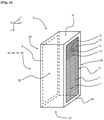
- the air extraction/insufflation flap 4a, 4b, 4c, 4d is illustrated inside an orthonormal mark Oxyz linked to the air extraction/insufflation flap 4a, 4b, 4c , 4d and comprising a longitudinal axis Ox, a transverse axis Oy and a lateral axis Oz.
- the air extraction/blowing flap 4a, 4b, 4c, 4d comprises a frame 8 which is shaped like a quadrilateral comprising two longitudinal edges 81 formed inside a respective plane parallel to the plane Oxy and two side edges 82 formed inside a respective plane parallel to the Oyz plane.
- Frame 8 delimits a first window 83 and a second window 84 formed inside a respective plane which is parallel to the plane Oxz.
- the first window 83 is equipped with a grille 10 which comprises at least one upright 11 which extends between the longitudinal edges 81 and parallel to the lateral edges 82.
- the grille 10 comprises two uprights 11.
- the uprights 11 interconnect fins 12 which extend parallel to the longitudinal axis Ox.
- the fins 12 are equidistant from each other along the uprights 11.
- the fins 12 are preferably inclined at a non-zero angle with respect to a plane parallel to the plane Oxz.
- the grid 10 has in particular an aesthetic aim and makes it possible to hide from view an interior volume of the frame 8 and the opening 9.
- the second window 84 is intended to be affixed against the mouth 6a, 6b, 6c, 6d of the air extraction/blowing duct 5.
- the second window 84 is equipped with an opening 9 which is movable between a first position in which the sash 9 closes off the second window 84 and a second position in which the sash 9 allows smoke to pass from the extraction/insufflation flap 4a, 4b, 4c, 4d towards the extraction duct / air blowing 5 through the mouth 6a, 6b, 6c, 6d and an air passage from the extraction duct / air blowing 5 to the extraction flap / 4a, 4b, 4c, 4d.
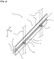
- the grid 10 On the picture 3 , the grid 10, of which only the uprights 11 have been shown and in dotted lines for better readability of the figure, is equipped with at least one closure profile 13 which is intended to partially obstruct the first window 83.
- the profile shutter 13 is intended to increase a pressure drop at the level of the air extraction/blowing flap 4a, 4b, 4c, 4d that the shutter profile 13 equips.
- the closure profile 13 comprises a strip 14 and at least one fastener 24 of the strip 14 on one of the uprights 11 of the grid 10. More specifically, the closure profile 13 comprises as many fasteners 24 that the grid 10 comprises uprights 11. According to the example shown, the closure profile 13 comprises a pair of fastening members 24.
- the blade 14 extends mainly along an axis of elongation A1 parallel to the longitudinal axis Ox, when the shutter profile 13 is mounted on the grid 10 of the air extraction/blowing flap 4a, 4b , 4c, 4d.
- the closure profile 13 comprises a first face 15 which is flat and which is made in a plane parallel to the Oxz plane.
- the first face 15 extends between two longitudinal flanges 16 which are parallel to the axis of elongation A1 and two lateral flanges 17 which are formed in respective planes orthogonal to the axis of elongation A1.
- the closure profile 13 comprises a second face 18, opposite the first face 15, which is for example curved.
- the closure profile 13 is for example produced by extrusion of a plastic/aluminum or other material.
- the blade 14 has a groove 19 which extends parallel to the axis of elongation A1 between the side flanges 17, the groove 19 being open through the latter.
- the groove 19 is arranged in a "T" and comprises a foot 20 which is made inside a plane parallel to the plane Oxz and an arm 21 which is made inside a plane parallel to the plane Oxy. Groove 19 also emerges through first face 15 via arm 21. Foot 20 extends between two lateral ends of foot 22 which are separated by a first length L1 taken parallel to axis Oz between the lateral ends of the foot 22.
- the foot 20 extends between two transverse ends of the foot 23 which are separated by a first thickness E1 taken parallel to the axis Oy between the transverse ends of the foot 23.
- the arm 21 is connected to the foot 20 via a first connection point 24 which is located at an equal distance from the lateral ends of the foot 22.
- the arm 21 has a first width X1 taken parallel to the axis Oz between two lateral ends of arms 25.
- the fixing member 26 comprises a base 27 which is of identical conformation to the foot 20 of the groove 19.
- the base 27 extends between two lateral ends of the base 28 which are separated by a second length L2 taken parallel to the axis Oz between the lateral ends of the base 28.
- the base 27 extends between two transverse ends of the base 29 which are separated by a second thickness E2 taken parallel to the axis Oy between the transverse ends of the base 29.
- the base 27 is provided with a pad 30 which is connected to the base 27 via a second connection point 31 located at equal distance from the lateral ends of the base 28.
- the pad 30 has a second width X2 taken parallel to the axis Oz between two lateral ends of stud 32.
- the first length L1 is equal to the second length L2
- the first thickness E1 is equal to the second thickness E2
- the first width X1 is equal to the second width X2.
- the stud 30 is equipped with a clip 33 which comprises two jaws 34 symmetrical to each other.
- the jaws 34 form between them an opening 35 which gives access to an internal space 36 capable of receiving one of the uprights 11 of the grid 10.
- the clip 33 is capable of being equipped with a system for closing the opening 35.
- the fixing members 26 are for example obtained by molding a plastic material, a thickness of the jaws 34 being adapted according to the plastic material used, so as to allow the upright 11 to pass through the opening 35 from an elastic deformation of the jaws 34.
- the clips 33 can also be made of steel, stainless steel or any other fire-resistant material.
- a number N of profiled shutters 13 fitted each of the air extraction/blowing flaps 4a, 4b, 4c, 4d of the smoke extraction installation 2 is a decreasing function of a distance D at which is placed each air extraction/blowing flap 4a, 4b, 4c, 4d on the air extraction/blowing duct 5.
- a function is in particular a step function.
- first air extraction/blowing flap 4a arranged at the first distance D1 from the air extraction fan 7 is provided with a greater or equal number of profiles d shutter 13 that the second air extraction/blowing flap 4b placed at the second distance D2 from the extraction/air blowing fan 7, to avoid an overflow of air and/or of fumes at the level of the first air extraction/blowing flap 4a.
- the number N of blanking profiles is either determined by calculation using software or tables.
Landscapes
- Engineering & Computer Science (AREA)
- Chemical & Material Sciences (AREA)
- Combustion & Propulsion (AREA)
- Mechanical Engineering (AREA)
- General Engineering & Computer Science (AREA)
- Air-Flow Control Members (AREA)
- Sampling And Sample Adjustment (AREA)
- Respiratory Apparatuses And Protective Means (AREA)
- Ventilation (AREA)
Claims (8)
- Klappe zum Ausleiten/Einleiten von Luft (4a, 4b, 4c, 4d) als Teil einer Rauchabzugsanlage (2), wobei die Klappe zum Ausleiten/Einleiten von Luft (4a, 4b, 4c, 4d) einen Rahmen (8) umfasst, der mindestens ein erstes Fenster (83) mit einem Gitter (10) begrenzt, das Rippen (12) aufweist, dadurch gekennzeichnet, dass die Klappe zum Ausleiten/Einleiten von Luft (4a, 4b, 4c, 4d) mindestens ein Verschlussprofil (13) des ersten Fensters (83) umfasst, das zwischen zwei Rippen (12) angeordnet ist, um einen bestimmten Lastverlust zu erzeugen, um einen gewählten Luftdurchsatz zu erhalten, der das erste Fenster (83) durchquert, wobei das Verschlussprofil (13) eine Lamelle (14) und ein Befestigungsorgan (26) der Lamelle (14) auf dem Gitter (10) umfasst.
- Klappe zum Ausleiten/Einleiten von Luft (4a, 4b, 4c, 4d) nach Anspruch 1, dadurch gekennzeichnet, dass die Lamelle (14) mit einer Nut (19) versehen ist, die imstande ist, das Befestigungsorgan (26) mindestens teilweise aufzunehmen.
- Klappe zum Ausleiten/Einleiten von Luft (4a, 4b, 4c, 4d) nach Anspruch 3, dadurch gekennzeichnet, dass das Befestigungsorgan (26) ein Befestigungsorgan durch Clippen auf einem Holm (11) ist, den das Gitter (10) umfasst.
- Klappe zum Ausleiten/Einleiten von Luft (4a, 4b, 4c, 4d) nach Anspruch 3, dadurch gekennzeichnet, dass das Befestigungsorgan (26) einen Clip (33) umfasst, der Backen (34) aufweist, die einen Innenraum (36) begrenzen, der imstande ist, den Holm (11) des Gitters (10) aufzunehmen.
- Klappe zum Ausleiten/Einleiten von Luft (4a, 4b, 4c, 4d) nach einem der vorangehenden Ansprüche, dadurch gekennzeichnet, dass der Rahmen (8) zwei Längsränder (81) und zwei Seitenränder (82) umfasst, die das erste Fenster (83) mit dem Gitter (10) und ein zweites Fenster (84) mit einem Flügel (9) begrenzen.
- Rauchabzugsanlage (2), umfassend eine Leitung zum Ausleiten/Einleiten von Luft (5), die mit einer Vielzahl von Klappen zum Ausleiten/Einleiten von Luft (4a, 4b, 4c, 4d) nach einem der vorangehenden Ansprüche ausgestattet ist, die in einem jeweiligen Abstand (D1, D2, D3, D4) von einem Lüfter zum Ausleiten/Einleiten von Luft (7) angeordnet sind, dadurch gekennzeichnet, dass eine Anzahl (N) von Verschlussprofil (13), das eine Klappe zum Ausleiten/Einleiten von Luft (4a, 4b, 4c, 4d) ausstattet, eine absteigende Funktion des Abstands (D1, D2, D3, D4) ist.
- Rauchabzugsanlage (2) nach Anspruch 6, dadurch gekennzeichnet, dass die Funktion eine treppenförmige diskrete Funktion ist.
- Verfahren zum Luftlastverlustausgleich einer Rauchabzugsanlage (2) nach einem der Ansprüche 6 und 7, dadurch gekennzeichnet, dass das Verfahren darin besteht, eine erste Klappe zum Ausleiten/Einleiten von Luft (4a, 4b, 4c, 4d), die in einem ersten Abstand (D1) vom Lüfter zum Ausleiten/Einleiten von Luft (7) angeordnet ist, mit einer ersten Anzahl (N1) von Verschlussprofilen (13) auszustatten, die größer oder gleich einer zweiten Anzahl (N2) von Verschlussprofilen (13) ist, die eine zweite Klappe zum Ausleiten/Einleiten von Luft (4a, 4b, 4c, 4d) ausstattet, die in einem zweiten Abstand (D2) vom Lüfter zum Ausleiten/Einleiten von Luft (7) angeordnet ist, der größer als der erste Abstand (D1) ist.
Applications Claiming Priority (1)
| Application Number | Priority Date | Filing Date | Title |
|---|---|---|---|
| FR1904450A FR3095501B1 (fr) | 2019-04-26 | 2019-04-26 | Installation de désenfumage |
Publications (2)
| Publication Number | Publication Date |
|---|---|
| EP3745039A1 EP3745039A1 (de) | 2020-12-02 |
| EP3745039B1 true EP3745039B1 (de) | 2022-01-19 |
Family
ID=67384116
Family Applications (1)
| Application Number | Title | Priority Date | Filing Date |
|---|---|---|---|
| EP20170274.3A Active EP3745039B1 (de) | 2019-04-26 | 2020-04-20 | Rauchabzugsanlage |
Country Status (2)
| Country | Link |
|---|---|
| EP (1) | EP3745039B1 (de) |
| FR (1) | FR3095501B1 (de) |
Citations (1)
| Publication number | Priority date | Publication date | Assignee | Title |
|---|---|---|---|---|
| EP1617155B1 (de) * | 2004-07-12 | 2007-11-28 | Autogyre | Lüftungsgitter |
Family Cites Families (6)
| Publication number | Priority date | Publication date | Assignee | Title |
|---|---|---|---|---|
| US5788571A (en) * | 1997-01-22 | 1998-08-04 | Ivison; John T. | Method of venting smoke from highrise residential buildings |
| NL1016184C2 (nl) * | 2000-09-14 | 2002-03-15 | System Engineering & Component | Roosterorgaan, bestemd voor plaatsing in een ventilatieopening. |
| US9759442B2 (en) * | 2005-12-27 | 2017-09-12 | American Aldes Ventilation Corporation | Method and apparatus for passively controlling airflow |
| US8517809B2 (en) * | 2006-04-12 | 2013-08-27 | Zero International, Inc. | Louver closure system and method |
| UA38413U (uk) * | 2008-08-28 | 2009-01-12 | Закрите Акціонерне Товариство "Вентиляційні Системи" | Вентиляційна решітка |
| US20180017281A1 (en) * | 2016-07-15 | 2018-01-18 | Richard Ebersohl | Vent Screening System |
-
2019
- 2019-04-26 FR FR1904450A patent/FR3095501B1/fr not_active Expired - Fee Related
-
2020
- 2020-04-20 EP EP20170274.3A patent/EP3745039B1/de active Active
Patent Citations (1)
| Publication number | Priority date | Publication date | Assignee | Title |
|---|---|---|---|---|
| EP1617155B1 (de) * | 2004-07-12 | 2007-11-28 | Autogyre | Lüftungsgitter |
Also Published As
| Publication number | Publication date |
|---|---|
| FR3095501A1 (fr) | 2020-10-30 |
| FR3095501B1 (fr) | 2021-07-23 |
| EP3745039A1 (de) | 2020-12-02 |
Similar Documents
| Publication | Publication Date | Title |
|---|---|---|
| EP3504382B1 (de) | Befestigungsprofil mit luftdurchlass und eine abgehängte deckenanordnung mit einem solchen profil | |
| US20010046838A1 (en) | Air handling system duct closure and heat trap | |
| US10907403B2 (en) | Replacement window panel with air conditioner coupling | |
| FR3095501A1 (fr) | Installation de désenfumage | |
| EP2360433B1 (de) | Mechanische Hilfsvorrichtung für die Ableitung von Gasflüssen, die insbesondere für Wohneinheiten bestimmt sind und Abluftverfahren | |
| KR100767069B1 (ko) | 처짐방지장치가 구비된 루버형 도어 | |
| KR101604819B1 (ko) | 환기구 | |
| JP3927191B2 (ja) | 鋼製ドア用郵便受及びこれを有する鋼製ドア | |
| AU2016252096A1 (en) | Improved jalousie window device | |
| EP3333992B1 (de) | Belüftungsgebläse im innern einer umhüllung zur aufnahme von modularen elektrischen geräten, und umhüllung, die eine solche vorrichtung umfasst | |
| US7125332B2 (en) | Ceiling radiation damper and mounting method | |
| FR2955883A1 (fr) | Cadre pour le montage d'un volet dans une installation aeraulique notamment de desenfumage | |
| WO2012013138A1 (zh) | 换气扇用的防火闸 | |
| EP3444416B1 (de) | Modulare anordnung für die ausstattung eines operationssaals | |
| FR3055344A1 (fr) | Profile d'accroche permettant le passage d'air et ensemble de plafond comprenant un tel profile | |
| EP2309833A1 (de) | Module für Netzwerk- und Serverschränke, und ihr Einbau | |
| EP4174392B1 (de) | Lüftungskasten und zugehörige lüftungsanlage | |
| KR102939717B1 (ko) | 에어덕트용 방화댐퍼 | |
| EP3002523B1 (de) | Kühl-, klimatisierungs- oder heizsystem mit teleskopmitteln zur lufttrennung | |
| JP7730300B2 (ja) | 排気フード | |
| CA3033061C (fr) | Profile d'accroche permettant le passage d'air et ensemble de plafond comprenant un tel profile | |
| CA2792809C (en) | Exhaust vent | |
| FR2847661A1 (fr) | Bouche d'extraction de gaz a membrane flexible de regulation | |
| EP3088273A1 (de) | Homogenes klimaanlagengerät eines wagens eines schienenfahrzeugs | |
| FR2723180A1 (fr) | Rideau d'air pour quais de chargement et dechargement de camions |
Legal Events
| Date | Code | Title | Description |
|---|---|---|---|
| PUAI | Public reference made under article 153(3) epc to a published international application that has entered the european phase |
Free format text: ORIGINAL CODE: 0009012 |
|
| STAA | Information on the status of an ep patent application or granted ep patent |
Free format text: STATUS: THE APPLICATION HAS BEEN PUBLISHED |
|
| AK | Designated contracting states |
Kind code of ref document: A1 Designated state(s): AL AT BE BG CH CY CZ DE DK EE ES FI FR GB GR HR HU IE IS IT LI LT LU LV MC MK MT NL NO PL PT RO RS SE SI SK SM TR |
|
| AX | Request for extension of the european patent |
Extension state: BA ME |
|
| STAA | Information on the status of an ep patent application or granted ep patent |
Free format text: STATUS: REQUEST FOR EXAMINATION WAS MADE |
|
| 17P | Request for examination filed |
Effective date: 20210505 |
|
| RBV | Designated contracting states (corrected) |
Designated state(s): AL AT BE BG CH CY CZ DE DK EE ES FI FR GB GR HR HU IE IS IT LI LT LU LV MC MK MT NL NO PL PT RO RS SE SI SK SM TR |
|
| GRAP | Despatch of communication of intention to grant a patent |
Free format text: ORIGINAL CODE: EPIDOSNIGR1 |
|
| STAA | Information on the status of an ep patent application or granted ep patent |
Free format text: STATUS: GRANT OF PATENT IS INTENDED |
|
| RIC1 | Information provided on ipc code assigned before grant |
Ipc: F24F 7/06 20060101ALI20210906BHEP Ipc: A62C 2/06 20060101ALI20210906BHEP Ipc: F24F 13/08 20060101ALI20210906BHEP Ipc: F24F 13/06 20060101ALI20210906BHEP Ipc: F24F 11/33 20180101AFI20210906BHEP |
|
| INTG | Intention to grant announced |
Effective date: 20210923 |
|
| GRAS | Grant fee paid |
Free format text: ORIGINAL CODE: EPIDOSNIGR3 |
|
| GRAA | (expected) grant |
Free format text: ORIGINAL CODE: 0009210 |
|
| STAA | Information on the status of an ep patent application or granted ep patent |
Free format text: STATUS: THE PATENT HAS BEEN GRANTED |
|
| AK | Designated contracting states |
Kind code of ref document: B1 Designated state(s): AL AT BE BG CH CY CZ DE DK EE ES FI FR GB GR HR HU IE IS IT LI LT LU LV MC MK MT NL NO PL PT RO RS SE SI SK SM TR |
|
| REG | Reference to a national code |
Ref country code: GB Ref legal event code: FG4D Free format text: NOT ENGLISH |
|
| REG | Reference to a national code |
Ref country code: CH Ref legal event code: EP |
|
| REG | Reference to a national code |
Ref country code: DE Ref legal event code: R096 Ref document number: 602020001642 Country of ref document: DE |
|
| REG | Reference to a national code |
Ref country code: AT Ref legal event code: REF Ref document number: 1464018 Country of ref document: AT Kind code of ref document: T Effective date: 20220215 |
|
| REG | Reference to a national code |
Ref country code: IE Ref legal event code: FG4D Free format text: LANGUAGE OF EP DOCUMENT: FRENCH |
|
| REG | Reference to a national code |
Ref country code: LT Ref legal event code: MG9D |
|
| REG | Reference to a national code |
Ref country code: NL Ref legal event code: MP Effective date: 20220119 |
|
| REG | Reference to a national code |
Ref country code: AT Ref legal event code: MK05 Ref document number: 1464018 Country of ref document: AT Kind code of ref document: T Effective date: 20220119 |
|
| PG25 | Lapsed in a contracting state [announced via postgrant information from national office to epo] |
Ref country code: NL Free format text: LAPSE BECAUSE OF FAILURE TO SUBMIT A TRANSLATION OF THE DESCRIPTION OR TO PAY THE FEE WITHIN THE PRESCRIBED TIME-LIMIT Effective date: 20220119 |
|
| PG25 | Lapsed in a contracting state [announced via postgrant information from national office to epo] |
Ref country code: SE Free format text: LAPSE BECAUSE OF FAILURE TO SUBMIT A TRANSLATION OF THE DESCRIPTION OR TO PAY THE FEE WITHIN THE PRESCRIBED TIME-LIMIT Effective date: 20220119 Ref country code: RS Free format text: LAPSE BECAUSE OF FAILURE TO SUBMIT A TRANSLATION OF THE DESCRIPTION OR TO PAY THE FEE WITHIN THE PRESCRIBED TIME-LIMIT Effective date: 20220119 Ref country code: PT Free format text: LAPSE BECAUSE OF FAILURE TO SUBMIT A TRANSLATION OF THE DESCRIPTION OR TO PAY THE FEE WITHIN THE PRESCRIBED TIME-LIMIT Effective date: 20220519 Ref country code: NO Free format text: LAPSE BECAUSE OF FAILURE TO SUBMIT A TRANSLATION OF THE DESCRIPTION OR TO PAY THE FEE WITHIN THE PRESCRIBED TIME-LIMIT Effective date: 20220419 Ref country code: LT Free format text: LAPSE BECAUSE OF FAILURE TO SUBMIT A TRANSLATION OF THE DESCRIPTION OR TO PAY THE FEE WITHIN THE PRESCRIBED TIME-LIMIT Effective date: 20220119 Ref country code: HR Free format text: LAPSE BECAUSE OF FAILURE TO SUBMIT A TRANSLATION OF THE DESCRIPTION OR TO PAY THE FEE WITHIN THE PRESCRIBED TIME-LIMIT Effective date: 20220119 Ref country code: ES Free format text: LAPSE BECAUSE OF FAILURE TO SUBMIT A TRANSLATION OF THE DESCRIPTION OR TO PAY THE FEE WITHIN THE PRESCRIBED TIME-LIMIT Effective date: 20220119 Ref country code: BG Free format text: LAPSE BECAUSE OF FAILURE TO SUBMIT A TRANSLATION OF THE DESCRIPTION OR TO PAY THE FEE WITHIN THE PRESCRIBED TIME-LIMIT Effective date: 20220419 |
|
| PG25 | Lapsed in a contracting state [announced via postgrant information from national office to epo] |
Ref country code: PL Free format text: LAPSE BECAUSE OF FAILURE TO SUBMIT A TRANSLATION OF THE DESCRIPTION OR TO PAY THE FEE WITHIN THE PRESCRIBED TIME-LIMIT Effective date: 20220119 Ref country code: LV Free format text: LAPSE BECAUSE OF FAILURE TO SUBMIT A TRANSLATION OF THE DESCRIPTION OR TO PAY THE FEE WITHIN THE PRESCRIBED TIME-LIMIT Effective date: 20220119 Ref country code: GR Free format text: LAPSE BECAUSE OF FAILURE TO SUBMIT A TRANSLATION OF THE DESCRIPTION OR TO PAY THE FEE WITHIN THE PRESCRIBED TIME-LIMIT Effective date: 20220420 Ref country code: FI Free format text: LAPSE BECAUSE OF FAILURE TO SUBMIT A TRANSLATION OF THE DESCRIPTION OR TO PAY THE FEE WITHIN THE PRESCRIBED TIME-LIMIT Effective date: 20220119 Ref country code: AT Free format text: LAPSE BECAUSE OF FAILURE TO SUBMIT A TRANSLATION OF THE DESCRIPTION OR TO PAY THE FEE WITHIN THE PRESCRIBED TIME-LIMIT Effective date: 20220119 |
|
| PG25 | Lapsed in a contracting state [announced via postgrant information from national office to epo] |
Ref country code: IS Free format text: LAPSE BECAUSE OF FAILURE TO SUBMIT A TRANSLATION OF THE DESCRIPTION OR TO PAY THE FEE WITHIN THE PRESCRIBED TIME-LIMIT Effective date: 20220519 |
|
| REG | Reference to a national code |
Ref country code: DE Ref legal event code: R097 Ref document number: 602020001642 Country of ref document: DE |
|
| PG25 | Lapsed in a contracting state [announced via postgrant information from national office to epo] |
Ref country code: SM Free format text: LAPSE BECAUSE OF FAILURE TO SUBMIT A TRANSLATION OF THE DESCRIPTION OR TO PAY THE FEE WITHIN THE PRESCRIBED TIME-LIMIT Effective date: 20220119 Ref country code: SK Free format text: LAPSE BECAUSE OF FAILURE TO SUBMIT A TRANSLATION OF THE DESCRIPTION OR TO PAY THE FEE WITHIN THE PRESCRIBED TIME-LIMIT Effective date: 20220119 Ref country code: RO Free format text: LAPSE BECAUSE OF FAILURE TO SUBMIT A TRANSLATION OF THE DESCRIPTION OR TO PAY THE FEE WITHIN THE PRESCRIBED TIME-LIMIT Effective date: 20220119 Ref country code: EE Free format text: LAPSE BECAUSE OF FAILURE TO SUBMIT A TRANSLATION OF THE DESCRIPTION OR TO PAY THE FEE WITHIN THE PRESCRIBED TIME-LIMIT Effective date: 20220119 Ref country code: DK Free format text: LAPSE BECAUSE OF FAILURE TO SUBMIT A TRANSLATION OF THE DESCRIPTION OR TO PAY THE FEE WITHIN THE PRESCRIBED TIME-LIMIT Effective date: 20220119 Ref country code: CZ Free format text: LAPSE BECAUSE OF FAILURE TO SUBMIT A TRANSLATION OF THE DESCRIPTION OR TO PAY THE FEE WITHIN THE PRESCRIBED TIME-LIMIT Effective date: 20220119 |
|
| REG | Reference to a national code |
Ref country code: DE Ref legal event code: R119 Ref document number: 602020001642 Country of ref document: DE |
|
| PLBE | No opposition filed within time limit |
Free format text: ORIGINAL CODE: 0009261 |
|
| STAA | Information on the status of an ep patent application or granted ep patent |
Free format text: STATUS: NO OPPOSITION FILED WITHIN TIME LIMIT |
|
| PG25 | Lapsed in a contracting state [announced via postgrant information from national office to epo] |
Ref country code: AL Free format text: LAPSE BECAUSE OF FAILURE TO SUBMIT A TRANSLATION OF THE DESCRIPTION OR TO PAY THE FEE WITHIN THE PRESCRIBED TIME-LIMIT Effective date: 20220119 |
|
| 26N | No opposition filed |
Effective date: 20221020 |
|
| REG | Reference to a national code |
Ref country code: BE Ref legal event code: MM Effective date: 20220430 |
|
| PG25 | Lapsed in a contracting state [announced via postgrant information from national office to epo] |
Ref country code: MC Free format text: LAPSE BECAUSE OF FAILURE TO SUBMIT A TRANSLATION OF THE DESCRIPTION OR TO PAY THE FEE WITHIN THE PRESCRIBED TIME-LIMIT Effective date: 20220119 Ref country code: LU Free format text: LAPSE BECAUSE OF NON-PAYMENT OF DUE FEES Effective date: 20220420 Ref country code: DE Free format text: LAPSE BECAUSE OF NON-PAYMENT OF DUE FEES Effective date: 20221103 |
|
| PG25 | Lapsed in a contracting state [announced via postgrant information from national office to epo] |
Ref country code: SI Free format text: LAPSE BECAUSE OF FAILURE TO SUBMIT A TRANSLATION OF THE DESCRIPTION OR TO PAY THE FEE WITHIN THE PRESCRIBED TIME-LIMIT Effective date: 20220119 Ref country code: BE Free format text: LAPSE BECAUSE OF NON-PAYMENT OF DUE FEES Effective date: 20220430 |
|
| PG25 | Lapsed in a contracting state [announced via postgrant information from national office to epo] |
Ref country code: IE Free format text: LAPSE BECAUSE OF NON-PAYMENT OF DUE FEES Effective date: 20220420 |
|
| P01 | Opt-out of the competence of the unified patent court (upc) registered |
Effective date: 20230527 |
|
| PG25 | Lapsed in a contracting state [announced via postgrant information from national office to epo] |
Ref country code: IT Free format text: LAPSE BECAUSE OF FAILURE TO SUBMIT A TRANSLATION OF THE DESCRIPTION OR TO PAY THE FEE WITHIN THE PRESCRIBED TIME-LIMIT Effective date: 20220119 |
|
| REG | Reference to a national code |
Ref country code: CH Ref legal event code: PL |
|
| PG25 | Lapsed in a contracting state [announced via postgrant information from national office to epo] |
Ref country code: LI Free format text: LAPSE BECAUSE OF NON-PAYMENT OF DUE FEES Effective date: 20230430 Ref country code: CH Free format text: LAPSE BECAUSE OF NON-PAYMENT OF DUE FEES Effective date: 20230430 |
|
| PG25 | Lapsed in a contracting state [announced via postgrant information from national office to epo] |
Ref country code: MK Free format text: LAPSE BECAUSE OF FAILURE TO SUBMIT A TRANSLATION OF THE DESCRIPTION OR TO PAY THE FEE WITHIN THE PRESCRIBED TIME-LIMIT Effective date: 20220119 Ref country code: CY Free format text: LAPSE BECAUSE OF FAILURE TO SUBMIT A TRANSLATION OF THE DESCRIPTION OR TO PAY THE FEE WITHIN THE PRESCRIBED TIME-LIMIT Effective date: 20220119 |
|
| PG25 | Lapsed in a contracting state [announced via postgrant information from national office to epo] |
Ref country code: HU Free format text: LAPSE BECAUSE OF FAILURE TO SUBMIT A TRANSLATION OF THE DESCRIPTION OR TO PAY THE FEE WITHIN THE PRESCRIBED TIME-LIMIT; INVALID AB INITIO Effective date: 20200420 |
|
| PG25 | Lapsed in a contracting state [announced via postgrant information from national office to epo] |
Ref country code: MT Free format text: LAPSE BECAUSE OF FAILURE TO SUBMIT A TRANSLATION OF THE DESCRIPTION OR TO PAY THE FEE WITHIN THE PRESCRIBED TIME-LIMIT Effective date: 20220119 |
|
| GBPC | Gb: european patent ceased through non-payment of renewal fee |
Effective date: 20240420 |
|
| PG25 | Lapsed in a contracting state [announced via postgrant information from national office to epo] |
Ref country code: GB Free format text: LAPSE BECAUSE OF NON-PAYMENT OF DUE FEES Effective date: 20240420 |
|
| PG25 | Lapsed in a contracting state [announced via postgrant information from national office to epo] |
Ref country code: GB Free format text: LAPSE BECAUSE OF NON-PAYMENT OF DUE FEES Effective date: 20240420 |
|
| PG25 | Lapsed in a contracting state [announced via postgrant information from national office to epo] |
Ref country code: TR Free format text: LAPSE BECAUSE OF FAILURE TO SUBMIT A TRANSLATION OF THE DESCRIPTION OR TO PAY THE FEE WITHIN THE PRESCRIBED TIME-LIMIT Effective date: 20220119 |
|
| PGFP | Annual fee paid to national office [announced via postgrant information from national office to epo] |
Ref country code: FR Payment date: 20260330 Year of fee payment: 7 |