EP3745061A1 - Kühl- und/oder gefriergerät - Google Patents
Kühl- und/oder gefriergerät Download PDFInfo
- Publication number
- EP3745061A1 EP3745061A1 EP20176055.0A EP20176055A EP3745061A1 EP 3745061 A1 EP3745061 A1 EP 3745061A1 EP 20176055 A EP20176055 A EP 20176055A EP 3745061 A1 EP3745061 A1 EP 3745061A1
- Authority
- EP
- European Patent Office
- Prior art keywords
- door
- refrigerator
- push rod
- freezer
- compartment
- Prior art date
- Legal status (The legal status is an assumption and is not a legal conclusion. Google has not performed a legal analysis and makes no representation as to the accuracy of the status listed.)
- Granted
Links
Images




Classifications
-
- F—MECHANICAL ENGINEERING; LIGHTING; HEATING; WEAPONS; BLASTING
- F25—REFRIGERATION OR COOLING; COMBINED HEATING AND REFRIGERATION SYSTEMS; HEAT PUMP SYSTEMS; MANUFACTURE OR STORAGE OF ICE; LIQUEFACTION SOLIDIFICATION OF GASES
- F25D—REFRIGERATORS; COLD ROOMS; ICE-BOXES; COOLING OR FREEZING APPARATUS NOT OTHERWISE PROVIDED FOR
- F25D23/00—General constructional features
- F25D23/02—Doors; Covers
-
- F—MECHANICAL ENGINEERING; LIGHTING; HEATING; WEAPONS; BLASTING
- F25—REFRIGERATION OR COOLING; COMBINED HEATING AND REFRIGERATION SYSTEMS; HEAT PUMP SYSTEMS; MANUFACTURE OR STORAGE OF ICE; LIQUEFACTION SOLIDIFICATION OF GASES
- F25D—REFRIGERATORS; COLD ROOMS; ICE-BOXES; COOLING OR FREEZING APPARATUS NOT OTHERWISE PROVIDED FOR
- F25D23/00—General constructional features
- F25D23/02—Doors; Covers
- F25D23/025—Secondary closures
-
- F—MECHANICAL ENGINEERING; LIGHTING; HEATING; WEAPONS; BLASTING
- F25—REFRIGERATION OR COOLING; COMBINED HEATING AND REFRIGERATION SYSTEMS; HEAT PUMP SYSTEMS; MANUFACTURE OR STORAGE OF ICE; LIQUEFACTION SOLIDIFICATION OF GASES
- F25D—REFRIGERATORS; COLD ROOMS; ICE-BOXES; COOLING OR FREEZING APPARATUS NOT OTHERWISE PROVIDED FOR
- F25D2323/00—General constructional features not provided for in other groups of this subclass
- F25D2323/02—Details of doors or covers not otherwise covered
- F25D2323/022—Doors that can be pivoted either left-handed or right-handed
Definitions
- the invention relates to a refrigerator and / or freezer with a compartment for storing refrigerated or frozen goods, which is optionally closed by means of a door that can be swung open to the left and to the right.
- doors In refrigerators and / or freezers, it can generally make sense for doors to be designed to open either to the left or to the right. Such concepts have also become known, for example, for doors which close a freezer compartment arranged within the normal refrigeration compartment from the normal refrigeration compartment.
- a disadvantage of these solutions is that a change in the configuration of the door is required for a change of the stop from left opening to right opening or vice versa, so that the user cannot freely decide whether he wants to open the door to the left or to the right for each operation.
- the object of the invention is to overcome these disadvantages and to provide a door which offers a high level of user comfort in that the user can freely decide for each operation whether he wants to open the door to the left or to the right.
- the invention relates to a refrigerator and / or freezer with a compartment for storing refrigerated or frozen goods, which is closed by means of a door, the door being a pivoting door which, in an unchanged configuration, either to the right as well as can be swiveled to the left.
- the door has vertical push rods on the left and right, of which one end, preferably the upper end, is inserted into a receptacle of the device in an initial position of the push rods, and which act as axes for opening the pivoting door to the left or to the right, the push rods being mounted vertically displaceably in the door so that they can be guided out of the receptacle in a vertical direction in order to assume an activated position.
- the receptacles are arranged above the door or above the second compartment and that the push rods can be guided out of the receptacles by vertical movement downwards.
- the other ends can each be inserted into a bearing block of the device from which they can be guided in the same direction by vertical movement.
- Each bearing block has, for example, a vertical bore into which an upwardly pointing extension at the lower end of the respective push rod is inserted from below.
- the respective push rod can have a shaped section in its lower area, in which it runs in an arc around the bearing block and runs back into the vertical below the bearing block.
- the extension can be arranged at the lower end of the molded section.
- the door has two handles, which are preferably arranged next to one another and / or on the underside of the door, and which are each connected to one of the push rods in such a way that when the handle is actuated, the respective push rod in the vertical direction is guided from the respective receptacle and preferably also from the respective bearing block.
- the handles can be handles, for example, which are arranged on the underside of the door and can be pivoted forward about a horizontal axis when actuated.
- the respective door side is simultaneously released for lifting from the removal opening by vertically shifting the respective push rod made up of the receptacle and bearing block.
- the door can be opened on this side.
- the push rod is still inserted into the receptacle and the bearing block so that the door can be pivoted open around the push rod on the other side.
- the push rods each have a driver which is connected to a driver contour on the respective handle in order to couple a movement of the handle with a vertical displacement of the push rod.
- the driver can be a horizontally protruding pin and the driver contour can be a laterally open rail guide for the pin, or vice versa.
- the push rods are pretensioned against movement from the respective receptacles and possibly from the respective bearing blocks, preferably by means of a mechanical spring arranged on the door.
- the push rods are biased into the starting position and against the activated position.
- the spring can be a compression spring.
- the door handle is spring-loaded and that the push rod moves along with it.
- corresponding latching means are formed on the push rod and on the door, which in the activated position of the push rod enter into a locking connection between the push rod and the door and prevent the push rod from being returned to its initial position.
- the latching means can be, for example, a notch and a corresponding projection, one of the latching means, for example the notch, being arranged on the push rod and the other of the latching means, for example the projection, being arranged on the door.
- one structural element can be arranged per push rod, which is designed to release the latching connection when the door is closed.
- the push rod is automatically reset to its original position by the pretension.
- the latching means of the door are each arranged on a spring element with a first ramp, and that a second ramp running in opposite directions to the first ramp is arranged on each of the bearing blocks, the two ramps running in opposite directions being designed so that during the last During the closing movement of the door, the spring element is bent out against the resetting force inherent in it so that the locking means of the push rod is released from the locking means of the door and the push rod is released for a vertical movement to return to the starting position.
- the refrigerator and / or freezer according to the invention can, in a preferred embodiment variant, be a device that has a first compartment, preferably a cooling space, and a second compartment, preferably a freezer compartment, arranged within the first compartment, the one formed according to the invention Door is arranged to close the second compartment from the first compartment.
- the door embodied according to the invention can therefore be a door which closes a freezer compartment arranged within the normal refrigerator compartment.
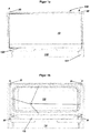
- Figures 1a and 1b show a front view of the uppermost area of a normal refrigerator compartment 110 of a refrigerator and / or freezer device 100 according to the invention, in which a freezer compartment 130 is located under the ceiling.
- a freezer compartment 130 is closed by means of the door 10.
- Figure 1b the same arrangement is shown without door 10.
- the freezer compartment 130 is formed by corresponding shaping of the deep-drawn device inner container 101 made of plastic.
- a horizontal partition 120 is formed in the inner container 101, which separates the freezer compartment 130 from the normal refrigerator compartment 110.
- the partition wall 120 is filled with an insulating material such as a thermal insulation foam in order to achieve a thermal decoupling of the normal cooling compartment 110 and the freezer compartment 130.
- the inner container 101 is shaped in the area of the freezer compartment 130 in such a way that a frame 131 with flat end faces is formed around the freezer compartment 130, which is used as a contact surface for a seal 11 of the door 10 (in the Figure 1 a hidden, but for example in Figure 3d visible), which in the closed position separates the freezer compartment 130 from the normal refrigerator compartment 110.
- two vertical blind holes 20 are formed at a small distance in front of the level of the removal opening of the freezer compartment 130, the vertical axes A of the blind holes 20 to the left and right of the removal opening, therefore at a small distance in front of the vertical sections of the frame 131 run.
- FIG Figures 2a and 2b show enlarged views of the area of the frame 131 in question.
- the area is in Figure 2a with inserted bearing block 30 and in the Figure 2b shown without bearing block 30 inserted therein.
- a latching recess 132 with a plurality of latching projections 133 is formed at the lateral end of the lower horizontal section of the frame 131, which lies below the freezer compartment 130 and is correspondingly formed by the front side of the partition 120.
- the bearing block 30 with a corresponding locking projection 31 (in the Figure 2a covered, but in Figure 7 visible) and is held in a form-fitting manner.
- the bearing block 30 has a vertical bore 32 which penetrates a region of the bearing block 30 from top to bottom.
- the bore 32 runs exactly in the extension of the axis A of the blind hole 20 arranged above the bearing block 30 shown in the ceiling.
- the bearing block 30 also has a web 33 projecting horizontally forwards next to the bore 32, the function of which will be explained in more detail below will be described.
- the opposite edge area (not shown) of the lower horizontal section of the frame 131 is designed in a mirror-inverted manner.
- bearing blocks 30 are covered from the front by the lower region of the door 10 and are not visible to the user when the door 10 is closed.
- Figures 3a-3e show sectional views through the freezer compartment door 10 and the surrounding areas.
- the cuts of the Figures 3a-3b are guided in the plane of the removal opening and run through the vertical pivot axes A.
- Figure 3a the entire width of the freezer compartment 130 is covered in Figure 3b only the right half.
- the cuts of the Figures 3c-3d are guided in a horizontal plane, in about mid-height of the door 10.
- Figure 3c the entire width of the freezer compartment 130 is covered in Figure 3d only the right area.
- the cut of the Figure 3e shows a vertical cross section through the door 10.
- a push rod 40 is guided vertically through a vertical passage 12 of the door 10 on the left and right.
- the passage 12 extends on the one hand to the upper edge of the door and is open at the top, and on the other hand extends into a lower area 13 of the door 10, which is open at the bottom and back and is only covered at the front by a front wall of the door 10 .
- the bearing block 30 is also arranged in this area 13.
- each of the push rods 40 protruding from the passage 12 and correspondingly protruding beyond the upper edge of the door 10 is inserted from below into the corresponding receptacle 20 on the right or left.
- the lower area of each of the push rods 40 protruding from the passage 12 into the area 13 of the door 10 has an arcuate section 42 formed from the axis A, which runs within the area 13 around the bearing block 30 and below the bearing block 30 again in steers in the area of axis A.
- a vertically upwardly projecting extension 43 is arranged, which is inserted from below into the bore 32 of the bearing block.
- FIG 4 shows a variant of the view according to Figure 1a , with push rods 40 being inserted into the receptacles 20 and bearing blocks 30 on the left and right, but in which the door is hidden.
- the extension 43 inserted into the bore 32 and the upper end 41 of the push rod 40 inserted into the receptacle 20 form upper and lower bearings for a pivoting movement of the door 10 about the vertical pivot axis A running through the bore 32 and the receptacle 20 to the left of the door a warehouse for a Pivoting the door 10 to the left and right on the door, a bearing for pivoting the door 10 to the right is present.
- the push rod 40 can, however, be displaced in the vertical direction in the passage 12 in such a way that the upper rod end 41 and the extension 43 can be pulled downward out of the receptacle 20 or the bore 32 by a vertical displacement. In this state, there is no longer any pivot bearing on the respective side, but instead the door 10 can be lifted off the frame 131 there.
- Each of the push rods 40 is by means of a compression spring not shown in the figures against their in Figures 3a and 3b
- the starting position shown is biased, in which its upper end 41 is inserted into the receptacle 20 and its extension 43 into the bore 32.
- the door 10 can be lifted from the frame 131 on one side on which the upper rod end 41 and the extension 43 are pulled down against the bias out of the receptacle 20 or the bore 32 and then around the axis A to pivot open the push rod 40 on the other side, the upper end 41 and extension 43 of which are still inserted into the corresponding receptacle 20 or bore 32.
- the door 10 can be pivoted open to the left or to the right.
- the central idea of the invention is that the door 10 in the current state, i.e. can be swiveled to the left as well as to the right without conversion. This means that a mechanism must be present on the door 10 which can optionally trigger a vertical displacement of the left and right push rod 40 against the bias of the compression spring downwards.
- the door comprises two handles 50 which are arranged on the right and left side by side on the underside of the door 10, specifically in the room 13.
- everyone who Handles 50 can be operated by a user after reaching behind the lower door area by pulling them forwards, that is to say in the opening direction of the door 10.
- the respective handle 50 Upon actuation, the respective handle 50 is tilted forward by a certain angle about a horizontal handle axis B running parallel to the plane of the removal opening.
- Each of the handles 50 is connected to one of the push rods 40 in such a way that when the handle 50 is actuated by a user as described, the push rod 40 is pulled vertically downward out of the receptacle 20 and the bore 32 of the bearing block 30 against the bias of the compression spring becomes.
- the handle 50 comprises, on its side facing the push rod 40, a pin 51 projecting horizontally in the direction of the push rod, which engages in a horizontal rail guide 44 of the push rod 40 facing the pin 51. In the event of a tilting movement of the handle 50 caused by actuation, the push rod 40 is pulled down slightly by means of this coupling.
- the left push rod 40 is pulled down against the bias of the compression spring, so that the upper rod end 41 is pulled out of the receptacle 20 and the extension 43 out of the bore 32 of the bearing block 30.
- the left side of the door 10 is thus unlocked and can be lifted forwards from the frame 131, which is also done by the pulling force exerted by the user forwards, which has already led to the activation of the handle 50 on the respective side.
- the door 10 is thus pivoted open to the left about the axis A formed by the push rod 40 on the right-hand side of the door 10, which is still in the starting position.
- Latching means in the form of a notch 45 formed on the push rod 40 and a projection 15 formed on the door 10, which engage in a locking connection in the activated position of the push rod 40, that is, after the push rod 40 has been pulled down by actuating the handle 50, which prevents the push rod 40 from being returned upwards into its starting position.
- the notch 45 of the push rod 40 is arranged at the end of a spring element 46 protruding from the arched area 42 of the push rod 40, which can be bent against a restoring force resulting from the material elasticity (to the left in the figure) that the edges the notch 45 can be lifted over the projection 15 and the projection 15 can snap into the notch.
- a mechanism is also provided to close the locking connection between projection 15 and notch 45 when the door is closed to solve.
- the bearing block 30 is also shown in a position in which it would be received in the receptacle 132.
- the web 33 of the bearing block comprises an inclined ramp 34 on the outside, against which an opposing ramp 47 on the spring element 46 abuts when the door 10 is closed.
- the opposing ramps 34 and 47 are designed and directed so that during the last phase of the closing movement of the door 10 the the spring element 46 is bent out against the restoring force inherent in it so that the notch 45 is lifted from the projection 15 and the push rod is released accordingly for a vertical movement for restoring the initial position.
- the mechanism described works both at the left end of the door 10 when the door 10 is opened by actuating the left door handle 50 and swinging it open to the left and then closing the door 10, as well as at the right end of the door 10 when the door 10 is opened Actuation of the right door handle 50 and swiveling it open to the right and then closing the door 10. For this purpose, no modifications need to be made to the door 10. It can be swiveled to the left as well as to the right as it is.
- FIGs 8a and 8b ultimately show perspective views of the freezer compartment 130 with the door 10 pivoted open to the left and to the right.
- the invention has the following features and advantages:
- the bearing block on the left and right at the bottom is mounted in the container through undercuts without additional parts.
- the door bearing is not visible when the door is closed.
- the door can always be opened on the left and right without moving any components.
- the door opening mechanism is not visible.
- the door is easy to assemble and dismantle, e.g. for cleaning by the customer.
Landscapes
- Engineering & Computer Science (AREA)
- Chemical & Material Sciences (AREA)
- Combustion & Propulsion (AREA)
- Physics & Mathematics (AREA)
- Mechanical Engineering (AREA)
- Thermal Sciences (AREA)
- General Engineering & Computer Science (AREA)
- Refrigerator Housings (AREA)
Abstract
Description
- Die Erfindung betrifft ein Kühl- und/oder Gefriergerät mit einem Kompartiment zur Aufbewahrung von Kühl- oder Gefriergut, das wahlweise anhand einer nach links und nach rechts aufschwenkbaren Tür verschlossen ist.
- In Kühl- und/oder Gefriergeräten kann es bei Türen generell sinnvoll sein, dass diese wahlweise links- und rechtsöffnend ausgebildet sind. Derartige Konzepte sind beispielsweise auch für Türen bekannt geworden, die ein innerhalb des Normalkühlfachs angeordnetes Gefrierfach gegenüber dem Normalkühlfach verschließen. Beispielsweise ist in diesem Zusammenhang auf die in den Druckschriften
DE 10 2008 044 131 A1 ,DE 10 2012 223 646 A1 undDE 10 2012 223 648 A1 vorgestellten Konzepte zu verweisen, wobei eine solche Tür wahlweise für eine Linksöffnung und eine Rechtsöffnung hergerichtet werden kann. - Nachteilig an diesen Lösungen ist jedoch, dass für einen Anschlagwechsel von Linksöffnung zu Rechtsöffnung oder umgekehrt jeweils eine Konfigurationsänderung der Tür erforderlich ist, wodurch der Benutzer nicht bei jeder Bedienung frei entscheiden kann, ob er die Tür nach links oder nach rechts öffnen will.
- Aufgabe der Erfindung ist es, diese Nachteile zu überwinden und eine Tür bereitzustellen, die einen hohen Benutzerkomfort bietet, indem der Benutzer bei jeder Bedienung frei entscheiden kann, ob er die Tür nach links oder nach rechts öffnen will.
- Vor diesem Hintergrund betrifft die Erfindung ein Kühl- und/oder Gefriergerät mit einem Kompartiment zur Aufbewahrung von Kühl- oder Gefriergut, das anhand einer Tür verschlossen ist, wobei es sich bei der Tür um eine Schwenktür handelt, die in unveränderter Konfiguration wahlweise sowohl nach rechts als auch nach links aufgeschwenkt werden kann.
- Im Gegensatz zum Stand der Technik ist es gemäß der Erfindung also nicht erforderlich, beispielsweise den Griff oder andere Funktionselemente der Tür von links nach rechts oder umgekehrt zu versetzen. Dies führt zu einem hohen Benutzerkomfort, da der Benutzer bei jeder Bedienung frei entscheiden kann, ob er die Tür nach links oder nach rechts öffnen will.
- Vorzugsweise ist vorgesehen, dass die Tür links und rechts jeweils vertikale Schubstangen aufweist, von denen ein Ende, vorzugsweise das obere Ende, in einer Ausgangsstellung der Schubstangen jeweils in eine Aufnahme des Geräts eingesteckt ist, und welche als Achsen für die Öffnung der Schwenktür nach links bzw. nach rechts bilden, wobei die Schubstangen vertikalverschieblich in der Tür gelagert sind, sodass sie in vertikaler Richtung aus der Aufnahme geführt werden können, um eine aktivierte Stellung einzunehmen.
- Weiter vorzugsweise ist dabei vorgesehen, dass die Aufnahmen oberhalb der Tür bzw. oberhalb des zweiten Kompartiments angeordnet sind und dass die Schubstangen durch vertikale Bewegung nach unten aus den Aufnahmen geführt werden können.
- Entsprechend können die anderen Enden, vorzugsweise die unteren Enden der Schubstangen, jeweils in einen Lagerbock des Geräts eingesteckt sein, aus dem sie durch vertikale Bewegung in dieselbe Richtung geführt werden können. Jeder Lagerbock weist beispielsweise eine vertikale Bohrung auf, in die ein nach oben zeigender Fortsatz am unteren Ende der jeweiligen Schubstange von unten her eingesteckt ist. Die jeweilige Schubstange kann zu diesem Zweck in ihrem unteren Bereich einen ausgeformten Abschnitt aufweisen, in dem sie in einem Bogen um den Lagerbock verläuft und unterhalb des Lagerbocks wieder in die Vertikale einläuft. Der Fortsatz kann am unteren Ende des ausgeformten Abschnitts angeordnet sein.
- Es kann weiterhin vorgesehen sein, dass die Tür zwei Griffe aufweist, die vorzugsweise nebeneinander und/oder an der Unterseite der Tür angeordnet sind, und die jeweils mit einer der Schubstangen derart verbunden sind, dass bei einer Betätigung des Griffs die jeweilige Schubstange in vertikaler Richtung aus der jeweiligen Aufnahme und vorzugsweise auch aus dem jeweiligen Lagerbock geführt wird. Bei den Griffen kann es sich beispielsweise um Griffe handeln, die an der Unterseite der Tür angeordnet sind und bei Betätigung um eine horizontale Achse nach vorne geschwenkt werden können.
- Wird also der Griff angezogen, wird gleichzeitig die jeweilige Türseite durch Vertikalverschiebung der jeweiligen Schubstange aus Aufnahme und Lagerbock für ein Abheben von der Entnahmeöffnung freigegeben. Die Tür kann an dieser Seite geöffnet werden. An der anderen Seite ist die Schubstange nach wie vor in die Aufnahme und in den Lagerbock eingesteckt, sodass die Tür um die Schubstange auf der anderen Seite aufgeschwenkt werden kann.
- In einer Ausführungsform weisen die Schubstangen jeweils einen Mitnehmer auf, der mit einer Mitnahmekontur am jeweiligen Griff in Verbindung steht, um eine Bewegung des Griffs mit einer Vertikalverschiebung der Schubstange zu koppeln. Beispielsweise kann es sich bei dem Mitnehmer um einen horizontal abstehenden Stift und bei der Mitnahmekontur um eine seitlich offene Schienenführung für den Stift handeln, oder umgekehrt.
- Vorzugsweise ist vorgesehen, dass die Schubstangen gegen eine Bewegung aus den jeweiligen Aufnahmen und gegebenenfalls aus den jeweiligen Lagerböcken vorgespannt sind, vorzugsweise anhand einer an der Tür angeordneten mechanischen Feder. Die Schubstangen sind in dieser Ausführungsform also mit anderen Worten in die Ausgangsstellung und gegen die aktivierte Stellung vorgespannt. Bei der Feder kann es sich um eine Druckfeder handeln.
- Alternativ oder zusätzlich dazu kann vorgesehen sein, dass der Türgriff gefedert gelagert ist und die Schubstange entsprechend mitbewegt.
- Weiterhin kann vorgesehen sein, dass an der Schubstange und an der Tür korrespondierende Rastmittel ausgebildet sind, die in der aktivierten Stellung der Schubstange eine Rastverbindung zwischen Schubstange und Tür eingehen und eine Rückstellung der Schubstange in ihre Ausgangsstellung verhindern. Bei den Rastmitteln kann es sich beispielsweise um eine Kerbe und einen korrespondierenden Vorsprung handeln, wobei eines der Rastmittel, beispielsweise die Kerbe, an der Schubstange und das andere der Rastmittel, beispielsweise der Vorsprung, an der Tür angeordnet ist.
- Am Gerät und vorzugsweise an den Lagerböcken kann pro Schubstange jeweils ein Strukturelement angeordnet sein, das ausgebildet ist, beim Schließen der Tür die Rastverbindung zu lösen. So wird die Schubstange bei geschlossener Tür dann durch die Vorspannung automatisch wieder in die Ausgangsposition rückgestellt. Dabei kann vorgesehen sein, dass die Rastmittel der Tür jeweils an einem Federelement mit einer ersten Rampe angeordnet ist, und dass an den Lagerböcken jeweils eine zur ersten Rampe gegenläufige zweite Rampe angeordnet ist, wobei die beiden gegenläufigen Rampen so ausgebildet sind, dass während der letzten Phase der Schließbewegung der Tür das Federelement gegen die ihm innewohnende Rückstellkraft so ausgebogen wird, dass das Rastmittel der Schubstange vom Rastmittel der Tür gelöst und die Schubstange für eine Vertikalbewegung zur Rückstellung in die Ausgangsstellung freigegeben wird.
- Bei dem erfindungsgemäßen Kühl- und/oder Gefriergerät kann es sich in einer bevorzugten Ausführungsvariante um ein Gerät handeln, das ein erstes Kompartiment, vorzugsweise einen Kühlraum, und ein innerhalb des ersten Kompartiments angeordnetes zweites Kompartiment, vorzugsweise ein Gefrierfach, aufweist, wobei die erfindungsgemäß ausgebildete Tür angeordnet ist, um das zweite Kompartiment gegenüber dem ersten Kompartiment zu verschließen. Bei der erfindungsgemäß ausgebildeten Tür kann es sich also um eine Tür handeln, die ein innerhalb des Normalkühlfachs angeordnetes Gefrierfach verschließt.
- Weitere Einzelheiten und Vorteile der Erfindung ergeben sich aus dem nachfolgend anhand der Figuren beschriebenen Ausführungsbeispiel. In den Figuren zeigen:
- Figur 1:
- Frontansichten auf das Gefrierfach eines erfindungsgemäßen Kühlund/oder Gefriergeräts mit und ohne Gefrierfachtür; und
- Figur 2:
- vergrößerte Ansichten eines Bereichs knapp unterhalb des Gefrierfachs mit und ohne Lagerbock;
- Figur 3:
- Schnittansichten der Gefrierfachtür und des umliegenden Bereichs inklusive Lagerbock und Aufnahme;
- Figur 4:
- eine Variante der Ansicht gemäß
Figur 1b mit eingesetzten Schubstangen; - Figur 5:
- Rückansichten der Tür mit Griff und Schubstange in Ausgangsposition und aktivierter Position;
- Figur 6:
- eine vergrößerte Ansicht eines Ausschnitts der
Figur 5a ; - Figur 7:
- eine weitere Ansicht des in
Figur 6 gezeigten Ausschnitts, wobei zudem der Lagerbock dargestellt ist; und - Figur 8:
- perspektivische Ansichten des Gefrierfachs mit nach links und nach rechts aufgeschwenkter Tür.
-
Figuren 1a und 1b zeigen eine Frontansicht des obersten Bereichs eines Normalkühlfachs 110 eines erfindungsgemäßen Kühl- und/oder Gefriergeräts 100, in dem sich ein unter der Decke angeordnetes Gefrierfach 130 befindet. InFigur 1a ist das Gefrierfach 130 anhand der Tür 10 verschlossen. InFigur 1b ist dieselbe Anordnung ohne Tür 10 gezeigt. - Das Gefrierfach 130 ist durch entsprechende Formgebung des tiefgezogenen Geräteinnenbehälters 101 aus Kunststoff gebildet. Insbesondere ist im Innenbehälter 101 eine horizontale Trennwand 120 ausgeformt, die das Gefrierfach 130 vom Normalkühlfach 110 trennt. Die Trennwand 120 ist mit einem Dämmmaterial wie beispielsweise einem Wärmeisolationsschaum gefüllt, um eine thermische Entkopplung des Normalkühlfachs 110 und des Gefrierfachs 130 zu erreichen. Des Weiteren ist der Innenbehälter 101 im Bereich des Gefrierfachs 130 so ausgeformt, dass rings um das Gefrierfach 130 ein Rahmen 131 mit ebenen Stirnflächen gebildet wird, die als Anlagefläche für eine Dichtung 11 der Tür 10 (in der
Figur 1 a verdeckt, aber beispielsweise inFigur 3d sichtbar) dienen, die in geschlossener Stellung das Gefrierfach 130 vom Normalkühlfach 110 abtrennt. - In der Decke des Normalkühlfachs 110 sind in geringem Abstand vor der Ebene der Entnahmeöffnung des Gefrierfachs 130 zwei vertikale Sacklöcher 20 ausgebildet, wobei die vertikalen Achsen A der Sacklöcher 20 links und rechts neben der Entnahmeöffnung, mithin also in geringem Abstand vor den vertikalen Abschnitten des Rahmens 131 verlaufen.
- An der horizontalen Stirnfläche des Rahmens 131, die unterhalb des Gefrierfachs 130 liegt und entsprechend durch die Vorderseite der Trennwand 120 gebildet wird, sind links und rechts neben der Entnahmeöffnung des Gefrierteils 130, nämlich in der Verlängerung der Achsen A der Sacklöcher 20, zwei Lagerböcke 30 angeordnet.
- Die Gestaltung der Lagerböcke 30 sowie deren Befestigung an der Vorderseite der Trennwand 120 lässt sich anhand der
Figuren 2a und 2b erkennen, die vergrößerte Ansichten des fraglichen Bereich des Rahmens 131 zeigen. Dabei ist der Bereich inFigur 2a mit eingesetztem Lagerbock 30 und in derFigur 2b ohne darin eingesetzten Lagerbock 30 gezeigt. - Wie dies insbesondere aus der
Figur 2b ersichtlich ist, ist am seitlichen Ende des unteren horizontalen Abschnitts des Rahmens 131, die unterhalb des Gefrierfachs 130 liegt und entsprechend durch die Vorderseite der Trennwand 120 gebildet wird, eine Rastvertiefung 132 mit mehreren Rastvorsprüngen 133 ausgebildet. In diese Rastvertiefung ist der Lagerbock 30 mit einem korrespondierenden Rastvorsprung 31 (in derFigur 2a verdeckt, aber inFigur 7 sichtbar) eingesetzt und wird darin formschlüssig gehalten. Der Lagerbock 30 weist eine vertikale Bohrung 32 auf, die einen Bereich des Lagerbocks 30 von oben bis unten durchdringt. Die Bohrung 32 verläuft genau in der Verlängerung der Achse A des oberhalb des gezeigten Lagerbocks 30 in der Decke angeordneten Sacklochs 20. Der Lagerbock 30 weist des Weiteren einen neben der Bohrung 32 horizontal nach vorne stehenden Steg 33 auf, dessen Funktion in weiterer Folge noch näher beschrieben werden wird. - Der nicht gezeigte, gegenüberliegende Randbereich des unteren horizontalen Abschnitts des Rahmens 131 ist spiegelverkehrt ausgebildet.
- Wie dies aus
Figur 1a zu erkennen ist, werden die Lagerböcke 30 von vorne von dem unteren Bereich der Tür 10 verdeckt und sind für den Benutzer bei geschlossener Tür 10 nicht sichtbar. -
Figuren 3a-3e zeigen Schnittansichten durch die Gefrierfachtür 10 und die umliegenden Bereiche. Die Schnitte derFiguren 3a-3b sind in der Ebene der Entnahmeöffnung geführt und verlaufen durch die vertikalen Schwenkachsen A. InFigur 3a ist dabei die gesamte Breite des Gefrierfachs 130 abgedeckt, inFigur 3b nur die rechte Hälfte. Die Schnitte derFiguren 3c-3d sind in einer horizontalen Ebene geführt, und zwar in etwa in mittlerer Höhe der Tür 10. InFigur 3c ist dabei die gesamte Breite des Gefrierfachs 130 abgedeckt, inFigur 3d nur der rechte Bereich. Der Schnitt derFigur 3e zeigt einen vertikalen Querschnitt durch die Tür 10. - Wie aus diesen Figuren zu erkennen ist, ist links und rechts jeweils eine Schubstange 40 vertikal durch einen vertikalen Durchgang 12 der Tür 10 geführt. Der Durchgang 12 reicht einerseits bis zur Oberkante der Tür und ist nach oben hin offen, und reicht andererseits bis in einen unteren Bereich 13 der Tür 10, welcher nach unten und hinten offen ist und lediglich nach vorne hin durch eine Vorderwand der Tür 10 verdeckt ist. In diesem Bereich 13 ist bei geschlossener Tür auch der Lagerbock 30 angeordnet.
- Das oben aus dem Durchgang 12 ragende und entsprechend über die Oberkante der Tür 10 hinausstehende obere Ende 41 jeder der Schubstangen 40 ist von unten in die korrespondierende Aufnahme 20 rechts bzw. links gesteckt. Der unten aus dem Durchgang 12 in den Bereich 13 der Tür 10 ragende untere Bereich jeder der Schubstangen 40 weist einen bogenförmig aus der Achse A ausgeformten Abschnitt 42 auf, der innerhalb des Bereichs 13 um den Lagerbock 30 herum verläuft und unterhalb des Lagerbocks 30 wieder in den Bereich der Achse A einlenkt. Am Bereich der Achse A befindlichen Ende der Schubstange 40 ist ein vertikal nach oben abstehender Fortsatz 43 angeordnet, der von unten in die Bohrung 32 des Lagerbocks eingesteckt ist.
- Die
Figur 4 zeigt eine Variante der Ansicht gemäßFigur 1a , wobei links und rechts Schubstangen 40 in die Aufnahmen 20 und Lagerböcke 30 eingesetzt sind, in der jedoch die Tür ausgeblendet ist. Anhand dieser Figur lassen sich die eben beschriebenen Sachverhalte gut nachvollziehen. - Der in die Bohrung 32 eingesteckte Fortsatz 43 und das in die Aufnahme 20 eingesteckte obere Ende 41 der Schubstange 40 bilden obere und untere Lager für eine Schwenkbewegung der Tür 10 um die durch die Bohrung 32 und die Aufnahme 20 verlaufende vertikale Schwenkachse A. Es ist also links an der Tür ein Lager für ein Aufschwenken der Tür 10 nach links und rechts an der Tür ein Lager für ein Aufschwenken der Tür 10 nach rechts vorhanden.
- Die Schubstange 40 kann im Durchgang 12 aber derart in vertikaler Richtung verschoben werden, dass das obere Stangenende 41 und der Fortsatz 43 durch eine Vertikalverschiebung nach unten aus der Aufnahme 20 bzw. der Bohrung 32 gezogen werden können. In diesem Zustand ist an der jeweiligen Seite kein Schwenklager mehr vorhanden, stattdessen kann die Tür 10 dort aber von dem Rahmen 131 abgehoben werden.
- Jede der Schubstangen 40 ist anhand einer in den Figuren nicht näher dargestellten Druckfeder gegen ihre in
Figuren 3a und3b dargestellte Ausgangsposition vorgespannt, in der ihr oberes Ende 41 in die Aufnahme 20 und ihr Fortsatz 43 in die Bohrung 32 gesteckt ist. - In Summe kann die Tür 10 also an einer Seite, an dem das obere Stangenende 41 und der Fortsatz 43 gegen die Vorspannung nach unten aus der Aufnahme 20 bzw. der Bohrung 32 gezogen, von dem Rahmen 131 abgehoben werden, um sie dann um die Achse A der Schubstange 40 der anderen Seite, deren oberes Ende 41 und Fortsatz 43 noch in die korrespondierende Aufnahme 20 bzw. Bohrung 32 gesteckt sind, aufzuschwenken. Je nach dem, auf welcher Seite die Schubstange 40 vertikal nach unten verschoben wird, kann die Tür 10 nach links oder nach rechts aufgeschwenkt werden.
- Kerngedanke der Erfindung ist es, dass die Tür 10 im Istzustand, d.h. ohne einen Umbau wahlweise sowohl nach links als auch nach rechts aufgeschwenkt werden kann. Dies bedeutet, dass an der Tür 10 ein Mechanismus vorhanden sein muss, der wahlweise eine Vertikalverschiebung der linken und der rechten Schubstange 40 gegen die Vorspannung der Druckfeder nach unten auslösen kann.
- Zu diesem Zweck umfasst die Tür zwei Griffe 50, die rechts und links nebeneinander an der Unterseite der Tür 10, konkret im Raum 13 angeordnet sind. Jeder der Griffe 50 kann von einem Benutzer nach Hintergreifen des unteren Türbereichs betätigt werden, indem er nach vorne, also in Öffnungsrichtung der Tür 10 gezogen werden. Bei Betätigung wird der jeweilige Griff 50 um eine horizontale und parallel zur Ebene der Entnahmeöffnung verlaufende Griffachse B um einen bestimmten Winkel nach vorne gekippt.
- Jeder der Griffe 50 ist mit einer der Schubstangen 40 derart verbunden, dass bei einer wie beschriebenen Betätigung des Griffs 50 durch einen Benutzer die Schubstange 40 gegen die Vorspannung der Druckfeder in vertikaler Richtung nach unten aus der Aufnahme 20 und der Bohrung 32 des Lagerbocks 30 gezogen wird. Zu diesem Zweck umfasst der Griff 50 an seiner der Schubstange 40 zugewandten Seite einen horizontal in Richtung der Schubstange abstehenden Stift 51, der in eine dem Stift 51 zugewandte, horizontale Schienenführung 44 der Schubstange 40 eingreift. Bei einer durch Betätigung hervorgerufenen Kippbewegung des Griffs 50 wird die Schubstange 40 anhand dieser Kopplung etwas nach unten gezogen.
- Diese Sachverhalte lassen sich gut anhand der
Figuren 5a und5b erkennen, welche die Tür 11 von hinten zeigen, einmal mit Griff 50 und Schubstange 40 in der Ausgangsposition (Figur 5a ) und einmal mit Griff 50 und Schubstange 40 in der aktivierten Position (Figur 5a ). - Wird also beispielsweise der linke Griff 50 betätigt, so wird die linke Schubstange 40 gegen die Vorspannung der Druckfeder nach unten gezogen, sodass das obere Stangenende 41 aus der Aufnahme 20 und der Fortsatz 43 aus der Bohrung 32 des Lagerbocks 30 gezogen werden. Die linke Seite der Tür 10 wird somit entriegelt und kann nach vorne vom Rahmen 131 abgehoben werden, was durch die vom Benutzer ausgeübte Zugkraft nach vorne, die bereits zur Aktivierung des Griffs 50 auf der jeweiligen Seite geführt hat, auch erfolgt. Die Tür 10 wird also um die von der Schubstange 40 auf der rechten Seite der Tür 10, die sich noch in der Ausgangsstellung befindet, gebildete Achse A nach links aufgeschwenkt.
- Um sicherzustellen, dass sich die aktivierte Schubstange nach einem Loslassen des Griffs 50 nicht bei geöffneter Tür 10 wieder durch die Vorspannung der Feder in die Ausgangsstellung zurückstellt, was ein Schließen der Tür 10 behindern würde, sind an der Schubstange 40 und an der Tür 10 korrespondierende Rastmittel in Form einer an der Schubstange 40 ausgebildeten Kerbe 45 und einem an der Tür 10 ausgebildeten Vorsprung 15 ausgebildet, die in der aktivierten Stellung der Schubstange 40, also nachdem die Schubstange 40 durch Betätigung des Griffs 50 nach unten gezogen wurde, eine Rastverbindung eingehen, die eine Rückstellung der Schubstange 40 nach oben in ihre Ausgangsstellung verhindert.
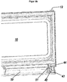
- Dies lässt sich besonders gut anhand der
Figur 6 nachvollziehen, die einen entsprechenden Ausschnitt derFigur 5b in vergrößerte Ansicht zeigt. Wie daraus erkennbar ist, ist die Kerbe 45 der Schubstange 40 am Ende eines vom bogenförmigen Bereich 42 der Schubstange 40 abstehenden Federelements 46 angeordnet, das gegen eine aus der Materialelastizität resultierende Rückstellkraft so ausgebogen werden kann (in der Figur nach links), dass die Ränder der Kerbe 45 über den Vorsprung 15 gehoben werden und der Vorsprung 15 in die Kerbe einrasten kann. - Um allerdings sicherzustellen, dass sich die aktivierte Schubstange nach dem Schließen der Tür wieder in ihre Ausgangsstellung zurückstellen kann, um die jeweilige Türseite wieder zu verriegeln, ist des Weiteren ein Mechanismus vorgesehen, um beim Schließen der Tür die Rastverbindung zwischen Vorsprung 15 und Kerbe 45 zu lösen.
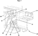
- Dieser Mechanismus lässt sich am besten anhand der
Figur 7 nachvollziehen, welche den inFigur 6 gezeigten Bereich der Tür noch einmal von schräg unten zeigt. Gegenüber derFigur 6 ist in derFigur 7 zudem der Lagerbock 30 in einer Position gezeigt, wie er in der Aufnahme 132 aufgenommen wäre. Wie daraus ersichtlich ist, umfasst der Steg 33 des Lagerbocks an der Außenseite eine schräge Rampe 34, an welche eine gegenläufige Rampe 47 am Federelement 46 beim Schließen der Tür 10 anstößt. Die gegenläufigen Rampen 34 und 47 sind dabei so ausgebildet und gerichtet, dass während der letzten Phase der Schließbewegung der Tür 10 die das Federelement 46 gegen die ihm innewohnende Rückstellkraft so ausgebogen wird, dass die Kerbe 45 vom Vorsprung 15 abgehoben wird und die Schubstange entsprechend für eine Vertikalbewegung zur Rückstellung in die Ausgangsstellung freigegeben wird. - Der beschriebene Mechanismus funktioniert sowohl am linken Ende der Tür 10 bei einem Öffnen der Tür 10 durch Betätigung des linken Türgriffs 50 und Aufschwenken nach links und dem anschließenden Schließen der Tür 10, als auch am rechten Ende der Tür 10 bei einem Öffnen der Tür 10 durch Betätigung des rechten Türgriffs 50 und Aufschwenken nach rechts und dem anschließenden Schließen der Tür 10. Dazu müssen keine Umbauten an der Tür 10 vorgenommen werden. Sie lässt sich so wie sie ist sowohl nach links als auch nach rechts aufschwenken.
-
Figuren 8a und 8b zeigen letztlich perspektivische Ansichten des Gefrierfachs 130 mit nach links und nach rechts aufgeschwenkter Tür 10. - In einer bevorzugten Ausgestaltung weist die Erfindung die folgenden Merkmale bzw. Vorteile auf:
Der Lagerbock links und rechts unten wird ohne Zusatzteil im Behälter durch Hinterschnitte montiert. - Die Türlagerung bei geschlossener Tür nicht sichtbar.
- Die Türöffnung links und rechts ist ohne umsetzen von Bauteilen immer möglich.
- Der Öffnungsmechanismus der Tür ist nicht sichtbar.
- Die Tür ist einfach montierbar und demontierbar, z.B. für die Reinigung durch den Kunden.
Claims (12)
- Kühl- und/oder Gefriergerät mit einem Kompartiment zur Aufbewahrung von Kühl- oder Gefriergut, das anhand einer Tür verschlossen ist,
dadurch gekennzeichnet,
dass es sich bei der Tür um eine Schwenktür handelt, die in unveränderter Konfiguration wahlweise sowohl nach rechts als auch nach links aufgeschwenkt werden kann. - Kühl- und/oder Gefriergerät nach Anspruch 1, dadurch gekennzeichnet, dass die Tür links und rechts jeweils vertikale Schubstangen aufweist, von denen ein Ende, vorzugsweise das obere Ende, in einer Ausgangsstellung der Schubstangen jeweils in eine Aufnahme des Geräts eingesteckt ist, und welche als Achsen für die Öffnung der Schwenktür nach links bzw. nach rechts bilden, wobei die Schubstangen vertikalverschieblich in der Tür gelagert sind, sodass sie in vertikaler Richtung aus der Aufnahme geführt werden können, um eine aktivierte Stellung einzunehmen.
- Kühl- und/oder Gefriergerät nach Anspruch 2, dadurch gekennzeichnet, dass die anderen Enden, vorzugsweise die unteren Enden der Schubstangen, jeweils in einen Lagerbock des Geräts eingesteckt sind, aus dem sie durch vertikale Bewegung in dieselbe Richtung geführt werden können.
- Kühl- und/oder Gefriergerät nach Anspruch 2 oder 3, dadurch gekennzeichnet, dass die Tür zwei Griffe aufweist, die vorzugsweise nebeneinander und/oder an der Unterseite der Tür angeordnet sind, und die jeweils mit einer der Schubstangen derart verbunden sind, dass bei einer Betätigung des Griffs die jeweilige Schubstange in vertikaler Richtung aus der jeweiligen Aufnahme und vorzugsweise auch aus dem jeweiligen Lagerbock geführt wird.
- Kühl- und/oder Gefriergerät nach Anspruch 4, dadurch gekennzeichnet, dass die Schubstangen jeweils einen Mitnehmer aufweisen, der mit einer Mitnahmekontur am jeweiligen Griff in Verbindung steht, um eine Bewegung des Griffs mit einer Vertikalverschiebung der Schubstange zu koppeln.
- Kühl- und/oder Gefriergerät nach einem der Ansprüche 2 bis 5, dadurch gekennzeichnet, dass die Schubstangen gegen eine Bewegung aus den jeweiligen Aufnahmen und gegebenenfalls aus den jeweiligen Lagerböcken vorgespannt ist, vorzugsweise anhand einer an der Tür angeordneten mechanischen Feder.
- Kühl- und/oder Gefriergerät nach Anspruch 6, dadurch gekennzeichnet, dass an der Schubstange und an der Tür korrespondierende Rastmittel ausgebildet sind, die in der aktivierten Stellung der Schubstange eine Rastverbindung eingehen und eine Rückstellung der Schubstange in ihre Ausgangsstellung verhindern.
- Kühl- und/oder Gefriergerät nach Anspruch 7, dadurch gekennzeichnet, dass am Gerät, vorzugsweise an den Lagerböcken, pro Schubstange jeweils ein Strukturelement angeordnet ist, das ausgebildet ist, beim Schließen der Tür die Rastverbindung zu lösen.
- Kühl- und/oder Gefriergerät nach Anspruch 8, dadurch gekennzeichnet, dass die Rastmittel der Tür jeweils an einem Federelement mit einer ersten Rampe angeordnet ist, und dass an den Lagerböcken jeweils eine zur ersten Rampe gegenläufige zweite Rampe angeordnet ist, wobei die beiden gegenläufigen Rampen so ausgebildet sind, dass während der letzten Phase der Schließbewegung der Tür das Federelement gegen die ihm innewohnende Rückstellkraft so ausgebogen wird, dass das Rastmittel der Schubstange vom Rastmittel der Tür gelöst und die Schubstange für eine Vertikalbewegung zur Rückstellung in die Ausgangsstellung freigegeben wird.
- Kühl- und/oder Gefriergerät nach einem der vorhergehenden Ansprüche, dadurch gekennzeichnet, dass das Gerät ein erstes Kompartiment, vorzugsweise einen Kühlraum, und ein innerhalb des ersten Kompartiments angeordnetes zweites Kompartiment, vorzugsweise ein Gefrierfach, aufweist, wobei die Tür das zweite Kompartiment gegenüber dem ersten Kompartiment verschließt.
- Kühl- und/oder Gefriergerät nach einem der Ansprüche 3 bis 10, dadurch gekennzeichnet, dass der oder die Lagerböcke ohne Zusatzteile, insbesondere ohne Verschraubung, durch einen oder mehrere Hinterschnitte vorzugsweise am Innenbehälter fixiert sind.
- Kühl- und/oder Gefriergerät nach einem der vorhergehenden Ansprüche, dadurch gekennzeichnet, dass die Türlagerung in einer Ansicht von vorne, d.h. für einen vor dem Gerät stehenden Betrachter, nicht sichtbar ist.
Applications Claiming Priority (2)
| Application Number | Priority Date | Filing Date | Title |
|---|---|---|---|
| DE102019114487 | 2019-05-29 | ||
| DE102019119089.4A DE102019119089A1 (de) | 2019-05-29 | 2019-07-15 | Kühl- und/oder Gefriergerät |
Publications (2)
| Publication Number | Publication Date |
|---|---|
| EP3745061A1 true EP3745061A1 (de) | 2020-12-02 |
| EP3745061B1 EP3745061B1 (de) | 2023-09-13 |
Family
ID=70804518
Family Applications (1)
| Application Number | Title | Priority Date | Filing Date |
|---|---|---|---|
| EP20176055.0A Active EP3745061B1 (de) | 2019-05-29 | 2020-05-22 | Kühl- und/oder gefriergerät |
Country Status (2)
| Country | Link |
|---|---|
| EP (1) | EP3745061B1 (de) |
| ES (1) | ES2965750T3 (de) |
Citations (5)
| Publication number | Priority date | Publication date | Assignee | Title |
|---|---|---|---|---|
| US2261146A (en) * | 1938-10-01 | 1941-11-04 | Dow Robert | Double hung door mounting and latching means |
| US2796628A (en) * | 1949-06-25 | 1957-06-25 | William J Van Meter | Double-hinged door |
| DE102008044131A1 (de) | 2008-11-27 | 2010-06-02 | BSH Bosch und Siemens Hausgeräte GmbH | Kältegerät mit zweiseitig anschlagbarer Tür |
| DE102012223648A1 (de) | 2012-12-18 | 2014-06-18 | BSH Bosch und Siemens Hausgeräte GmbH | Tür für ein Haushaltskältegerät mit einem zerlegefrei positionell verschiebbaren Griffteil sowie Haushaltskältegerät und Verfahren zur Positionierung eines Griffteils |
| DE102012223646A1 (de) | 2012-12-18 | 2014-07-24 | BSH Bosch und Siemens Hausgeräte GmbH | Haushaltskältegerät mit im Kühlfach innenliegenden Gefrierfach und längenveränderlichem Schieber |
-
2020
- 2020-05-22 EP EP20176055.0A patent/EP3745061B1/de active Active
- 2020-05-22 ES ES20176055T patent/ES2965750T3/es active Active
Patent Citations (5)
| Publication number | Priority date | Publication date | Assignee | Title |
|---|---|---|---|---|
| US2261146A (en) * | 1938-10-01 | 1941-11-04 | Dow Robert | Double hung door mounting and latching means |
| US2796628A (en) * | 1949-06-25 | 1957-06-25 | William J Van Meter | Double-hinged door |
| DE102008044131A1 (de) | 2008-11-27 | 2010-06-02 | BSH Bosch und Siemens Hausgeräte GmbH | Kältegerät mit zweiseitig anschlagbarer Tür |
| DE102012223648A1 (de) | 2012-12-18 | 2014-06-18 | BSH Bosch und Siemens Hausgeräte GmbH | Tür für ein Haushaltskältegerät mit einem zerlegefrei positionell verschiebbaren Griffteil sowie Haushaltskältegerät und Verfahren zur Positionierung eines Griffteils |
| DE102012223646A1 (de) | 2012-12-18 | 2014-07-24 | BSH Bosch und Siemens Hausgeräte GmbH | Haushaltskältegerät mit im Kühlfach innenliegenden Gefrierfach und längenveränderlichem Schieber |
Also Published As
| Publication number | Publication date |
|---|---|
| ES2965750T3 (es) | 2024-04-16 |
| EP3745061B1 (de) | 2023-09-13 |
Similar Documents
| Publication | Publication Date | Title |
|---|---|---|
| EP2054573B1 (de) | Öffnungsvorrichtung für relativ zueinander bewegliche möbelteile | |
| EP1690473B1 (de) | Touch-Latch System für Möbel mit zueinander relativ bewegbaren Möbelteilen, insbesondere Möbelschubladen, Möbeltüre oder Möbelklappe | |
| WO2009115133A1 (de) | Kältegerät und zugehörige einteilige rastmittelanordnung | |
| EP2005090A2 (de) | Kältegerät mit zwei türen | |
| WO2016145465A1 (de) | Befestigungsvorrichtung zum lösbaren befestigen einer frontblende an einer schublade | |
| DE202005002433U1 (de) | Touch-Latch System für Möbel mit zueinander relativ bewegbaren Möbelteilen, insbesondere Möbelschubladen, Möbeltüren oder Möbelklappe | |
| AT500212B1 (de) | Schublade | |
| DE3600211C1 (de) | Fenster- und Tuerbeschlag | |
| EP2746706B1 (de) | Kältegerät mit veränderbarem Türanschlag | |
| EP2746703A2 (de) | Tür für ein Haushaltskältegerät mit einem zerlegefrei positionell verschiebbaren Griffteil sowie Haushaltskältegerät und Verfahren zur Positionierung eines Griffteils | |
| EP2441905B1 (de) | Schloss | |
| EP3589810B1 (de) | Türsystem für ein kühlgerät | |
| EP3379180B1 (de) | Haushaltsgerätevorrichtung mit einem korpus, einem verschlusselement sowie einer an dem korpus und an dem verschlusselement befestigten leitung | |
| EP3745061B1 (de) | Kühl- und/oder gefriergerät | |
| EP3487359B1 (de) | Ausstossvorrichtung für ein bewegbares möbelteil und möbel | |
| EP2482015A2 (de) | Kühlschrank | |
| EP2514889B1 (de) | Türöffner | |
| DE102019119089A1 (de) | Kühl- und/oder Gefriergerät | |
| EP2746705A2 (de) | Haushaltskältegerät mit im Kühlfach innenliegenden Gefrierfach und längenveränderlichem Schieber | |
| DE102020117965A1 (de) | Kühl- und/oder Gefriergerät | |
| DE102021121416A1 (de) | Kühl- und/oder Gefriergerät | |
| DE102004062306A1 (de) | Kältegerät mit Türöffnungshilfe | |
| DE10357721B4 (de) | Verschlußvorrichtung für Türen oder Fenster | |
| WO2007131554A1 (de) | Tür für einen abtrennbaren innenraum | |
| EP3217129B1 (de) | Kühl- und/oder gefriergerät |
Legal Events
| Date | Code | Title | Description |
|---|---|---|---|
| PUAI | Public reference made under article 153(3) epc to a published international application that has entered the european phase |
Free format text: ORIGINAL CODE: 0009012 |
|
| STAA | Information on the status of an ep patent application or granted ep patent |
Free format text: STATUS: THE APPLICATION HAS BEEN PUBLISHED |
|
| AK | Designated contracting states |
Kind code of ref document: A1 Designated state(s): AL AT BE BG CH CY CZ DE DK EE ES FI FR GB GR HR HU IE IS IT LI LT LU LV MC MK MT NL NO PL PT RO RS SE SI SK SM TR |
|
| AX | Request for extension of the european patent |
Extension state: BA ME |
|
| STAA | Information on the status of an ep patent application or granted ep patent |
Free format text: STATUS: REQUEST FOR EXAMINATION WAS MADE |
|
| 17P | Request for examination filed |
Effective date: 20210601 |
|
| RBV | Designated contracting states (corrected) |
Designated state(s): AL AT BE BG CH CY CZ DE DK EE ES FI FR GB GR HR HU IE IS IT LI LT LU LV MC MK MT NL NO PL PT RO RS SE SI SK SM TR |
|
| GRAP | Despatch of communication of intention to grant a patent |
Free format text: ORIGINAL CODE: EPIDOSNIGR1 |
|
| STAA | Information on the status of an ep patent application or granted ep patent |
Free format text: STATUS: GRANT OF PATENT IS INTENDED |
|
| INTG | Intention to grant announced |
Effective date: 20230425 |
|
| GRAS | Grant fee paid |
Free format text: ORIGINAL CODE: EPIDOSNIGR3 |
|
| GRAA | (expected) grant |
Free format text: ORIGINAL CODE: 0009210 |
|
| STAA | Information on the status of an ep patent application or granted ep patent |
Free format text: STATUS: THE PATENT HAS BEEN GRANTED |
|
| AK | Designated contracting states |
Kind code of ref document: B1 Designated state(s): AL AT BE BG CH CY CZ DE DK EE ES FI FR GB GR HR HU IE IS IT LI LT LU LV MC MK MT NL NO PL PT RO RS SE SI SK SM TR |
|
| REG | Reference to a national code |
Ref country code: CH Ref legal event code: EP |
|
| REG | Reference to a national code |
Ref country code: DE Ref legal event code: R096 Ref document number: 502020005200 Country of ref document: DE |
|
| REG | Reference to a national code |
Ref country code: IE Ref legal event code: FG4D Free format text: LANGUAGE OF EP DOCUMENT: GERMAN |
|
| REG | Reference to a national code |
Ref country code: LT Ref legal event code: MG9D |
|
| REG | Reference to a national code |
Ref country code: NL Ref legal event code: MP Effective date: 20230913 |
|
| PG25 | Lapsed in a contracting state [announced via postgrant information from national office to epo] |
Ref country code: GR Free format text: LAPSE BECAUSE OF FAILURE TO SUBMIT A TRANSLATION OF THE DESCRIPTION OR TO PAY THE FEE WITHIN THE PRESCRIBED TIME-LIMIT Effective date: 20231214 |
|
| PG25 | Lapsed in a contracting state [announced via postgrant information from national office to epo] |
Ref country code: SE Free format text: LAPSE BECAUSE OF FAILURE TO SUBMIT A TRANSLATION OF THE DESCRIPTION OR TO PAY THE FEE WITHIN THE PRESCRIBED TIME-LIMIT Effective date: 20230913 Ref country code: RS Free format text: LAPSE BECAUSE OF FAILURE TO SUBMIT A TRANSLATION OF THE DESCRIPTION OR TO PAY THE FEE WITHIN THE PRESCRIBED TIME-LIMIT Effective date: 20230913 Ref country code: NO Free format text: LAPSE BECAUSE OF FAILURE TO SUBMIT A TRANSLATION OF THE DESCRIPTION OR TO PAY THE FEE WITHIN THE PRESCRIBED TIME-LIMIT Effective date: 20231213 Ref country code: LV Free format text: LAPSE BECAUSE OF FAILURE TO SUBMIT A TRANSLATION OF THE DESCRIPTION OR TO PAY THE FEE WITHIN THE PRESCRIBED TIME-LIMIT Effective date: 20230913 Ref country code: LT Free format text: LAPSE BECAUSE OF FAILURE TO SUBMIT A TRANSLATION OF THE DESCRIPTION OR TO PAY THE FEE WITHIN THE PRESCRIBED TIME-LIMIT Effective date: 20230913 Ref country code: HR Free format text: LAPSE BECAUSE OF FAILURE TO SUBMIT A TRANSLATION OF THE DESCRIPTION OR TO PAY THE FEE WITHIN THE PRESCRIBED TIME-LIMIT Effective date: 20230913 Ref country code: GR Free format text: LAPSE BECAUSE OF FAILURE TO SUBMIT A TRANSLATION OF THE DESCRIPTION OR TO PAY THE FEE WITHIN THE PRESCRIBED TIME-LIMIT Effective date: 20231214 Ref country code: FI Free format text: LAPSE BECAUSE OF FAILURE TO SUBMIT A TRANSLATION OF THE DESCRIPTION OR TO PAY THE FEE WITHIN THE PRESCRIBED TIME-LIMIT Effective date: 20230913 |
|
| PG25 | Lapsed in a contracting state [announced via postgrant information from national office to epo] |
Ref country code: NL Free format text: LAPSE BECAUSE OF FAILURE TO SUBMIT A TRANSLATION OF THE DESCRIPTION OR TO PAY THE FEE WITHIN THE PRESCRIBED TIME-LIMIT Effective date: 20230913 |
|
| PG25 | Lapsed in a contracting state [announced via postgrant information from national office to epo] |
Ref country code: IS Free format text: LAPSE BECAUSE OF FAILURE TO SUBMIT A TRANSLATION OF THE DESCRIPTION OR TO PAY THE FEE WITHIN THE PRESCRIBED TIME-LIMIT Effective date: 20240113 |
|
| REG | Reference to a national code |
Ref country code: ES Ref legal event code: FG2A Ref document number: 2965750 Country of ref document: ES Kind code of ref document: T3 Effective date: 20240416 |
|
| PG25 | Lapsed in a contracting state [announced via postgrant information from national office to epo] |
Ref country code: SM Free format text: LAPSE BECAUSE OF FAILURE TO SUBMIT A TRANSLATION OF THE DESCRIPTION OR TO PAY THE FEE WITHIN THE PRESCRIBED TIME-LIMIT Effective date: 20230913 Ref country code: RO Free format text: LAPSE BECAUSE OF FAILURE TO SUBMIT A TRANSLATION OF THE DESCRIPTION OR TO PAY THE FEE WITHIN THE PRESCRIBED TIME-LIMIT Effective date: 20230913 Ref country code: IS Free format text: LAPSE BECAUSE OF FAILURE TO SUBMIT A TRANSLATION OF THE DESCRIPTION OR TO PAY THE FEE WITHIN THE PRESCRIBED TIME-LIMIT Effective date: 20240113 Ref country code: EE Free format text: LAPSE BECAUSE OF FAILURE TO SUBMIT A TRANSLATION OF THE DESCRIPTION OR TO PAY THE FEE WITHIN THE PRESCRIBED TIME-LIMIT Effective date: 20230913 Ref country code: CZ Free format text: LAPSE BECAUSE OF FAILURE TO SUBMIT A TRANSLATION OF THE DESCRIPTION OR TO PAY THE FEE WITHIN THE PRESCRIBED TIME-LIMIT Effective date: 20230913 Ref country code: PT Free format text: LAPSE BECAUSE OF FAILURE TO SUBMIT A TRANSLATION OF THE DESCRIPTION OR TO PAY THE FEE WITHIN THE PRESCRIBED TIME-LIMIT Effective date: 20240115 Ref country code: SK Free format text: LAPSE BECAUSE OF FAILURE TO SUBMIT A TRANSLATION OF THE DESCRIPTION OR TO PAY THE FEE WITHIN THE PRESCRIBED TIME-LIMIT Effective date: 20230913 |
|
| PG25 | Lapsed in a contracting state [announced via postgrant information from national office to epo] |
Ref country code: PL Free format text: LAPSE BECAUSE OF FAILURE TO SUBMIT A TRANSLATION OF THE DESCRIPTION OR TO PAY THE FEE WITHIN THE PRESCRIBED TIME-LIMIT Effective date: 20230913 |
|
| REG | Reference to a national code |
Ref country code: DE Ref legal event code: R097 Ref document number: 502020005200 Country of ref document: DE |
|
| PG25 | Lapsed in a contracting state [announced via postgrant information from national office to epo] |
Ref country code: DK Free format text: LAPSE BECAUSE OF FAILURE TO SUBMIT A TRANSLATION OF THE DESCRIPTION OR TO PAY THE FEE WITHIN THE PRESCRIBED TIME-LIMIT Effective date: 20230913 |
|
| PLBE | No opposition filed within time limit |
Free format text: ORIGINAL CODE: 0009261 |
|
| STAA | Information on the status of an ep patent application or granted ep patent |
Free format text: STATUS: NO OPPOSITION FILED WITHIN TIME LIMIT |
|
| PG25 | Lapsed in a contracting state [announced via postgrant information from national office to epo] |
Ref country code: DK Free format text: LAPSE BECAUSE OF FAILURE TO SUBMIT A TRANSLATION OF THE DESCRIPTION OR TO PAY THE FEE WITHIN THE PRESCRIBED TIME-LIMIT Effective date: 20230913 |
|
| 26N | No opposition filed |
Effective date: 20240614 |
|
| PG25 | Lapsed in a contracting state [announced via postgrant information from national office to epo] |
Ref country code: SI Free format text: LAPSE BECAUSE OF FAILURE TO SUBMIT A TRANSLATION OF THE DESCRIPTION OR TO PAY THE FEE WITHIN THE PRESCRIBED TIME-LIMIT Effective date: 20230913 |
|
| PG25 | Lapsed in a contracting state [announced via postgrant information from national office to epo] |
Ref country code: SI Free format text: LAPSE BECAUSE OF FAILURE TO SUBMIT A TRANSLATION OF THE DESCRIPTION OR TO PAY THE FEE WITHIN THE PRESCRIBED TIME-LIMIT Effective date: 20230913 |
|
| PG25 | Lapsed in a contracting state [announced via postgrant information from national office to epo] |
Ref country code: BG Free format text: LAPSE BECAUSE OF FAILURE TO SUBMIT A TRANSLATION OF THE DESCRIPTION OR TO PAY THE FEE WITHIN THE PRESCRIBED TIME-LIMIT Effective date: 20230913 |
|
| PG25 | Lapsed in a contracting state [announced via postgrant information from national office to epo] |
Ref country code: BG Free format text: LAPSE BECAUSE OF FAILURE TO SUBMIT A TRANSLATION OF THE DESCRIPTION OR TO PAY THE FEE WITHIN THE PRESCRIBED TIME-LIMIT Effective date: 20230913 |
|
| REG | Reference to a national code |
Ref country code: CH Ref legal event code: PL |
|
| PG25 | Lapsed in a contracting state [announced via postgrant information from national office to epo] |
Ref country code: MC Free format text: LAPSE BECAUSE OF FAILURE TO SUBMIT A TRANSLATION OF THE DESCRIPTION OR TO PAY THE FEE WITHIN THE PRESCRIBED TIME-LIMIT Effective date: 20230913 |
|
| PG25 | Lapsed in a contracting state [announced via postgrant information from national office to epo] |
Ref country code: LU Free format text: LAPSE BECAUSE OF NON-PAYMENT OF DUE FEES Effective date: 20240522 |
|
| GBPC | Gb: european patent ceased through non-payment of renewal fee |
Effective date: 20240522 |
|
| PG25 | Lapsed in a contracting state [announced via postgrant information from national office to epo] |
Ref country code: MC Free format text: LAPSE BECAUSE OF FAILURE TO SUBMIT A TRANSLATION OF THE DESCRIPTION OR TO PAY THE FEE WITHIN THE PRESCRIBED TIME-LIMIT Effective date: 20230913 Ref country code: LU Free format text: LAPSE BECAUSE OF NON-PAYMENT OF DUE FEES Effective date: 20240522 Ref country code: CH Free format text: LAPSE BECAUSE OF NON-PAYMENT OF DUE FEES Effective date: 20240531 |
|
| REG | Reference to a national code |
Ref country code: BE Ref legal event code: MM Effective date: 20240531 |
|
| PG25 | Lapsed in a contracting state [announced via postgrant information from national office to epo] |
Ref country code: IE Free format text: LAPSE BECAUSE OF NON-PAYMENT OF DUE FEES Effective date: 20240522 |
|
| PG25 | Lapsed in a contracting state [announced via postgrant information from national office to epo] |
Ref country code: BE Free format text: LAPSE BECAUSE OF NON-PAYMENT OF DUE FEES Effective date: 20240531 |
|
| PG25 | Lapsed in a contracting state [announced via postgrant information from national office to epo] |
Ref country code: GB Free format text: LAPSE BECAUSE OF NON-PAYMENT OF DUE FEES Effective date: 20240522 |
|
| PGFP | Annual fee paid to national office [announced via postgrant information from national office to epo] |
Ref country code: DE Payment date: 20250602 Year of fee payment: 6 |
|
| PGFP | Annual fee paid to national office [announced via postgrant information from national office to epo] |
Ref country code: ES Payment date: 20250602 Year of fee payment: 6 |
|
| PGFP | Annual fee paid to national office [announced via postgrant information from national office to epo] |
Ref country code: IT Payment date: 20250529 Year of fee payment: 6 |
|
| PGFP | Annual fee paid to national office [announced via postgrant information from national office to epo] |
Ref country code: FR Payment date: 20250520 Year of fee payment: 6 |
|
| PGFP | Annual fee paid to national office [announced via postgrant information from national office to epo] |
Ref country code: AT Payment date: 20250721 Year of fee payment: 5 |
|
| PG25 | Lapsed in a contracting state [announced via postgrant information from national office to epo] |
Ref country code: CY Free format text: LAPSE BECAUSE OF FAILURE TO SUBMIT A TRANSLATION OF THE DESCRIPTION OR TO PAY THE FEE WITHIN THE PRESCRIBED TIME-LIMIT; INVALID AB INITIO Effective date: 20200522 |
|
| PG25 | Lapsed in a contracting state [announced via postgrant information from national office to epo] |
Ref country code: HU Free format text: LAPSE BECAUSE OF FAILURE TO SUBMIT A TRANSLATION OF THE DESCRIPTION OR TO PAY THE FEE WITHIN THE PRESCRIBED TIME-LIMIT; INVALID AB INITIO Effective date: 20200522 |