EP3745065B1 - Réacteur de production de vapeur d'eau et de substance sèche - Google Patents
Réacteur de production de vapeur d'eau et de substance sèche Download PDFInfo
- Publication number
- EP3745065B1 EP3745065B1 EP20401026.8A EP20401026A EP3745065B1 EP 3745065 B1 EP3745065 B1 EP 3745065B1 EP 20401026 A EP20401026 A EP 20401026A EP 3745065 B1 EP3745065 B1 EP 3745065B1
- Authority
- EP
- European Patent Office
- Prior art keywords
- reactor
- mass
- converted
- heating
- filling chamber
- Prior art date
- Legal status (The legal status is an assumption and is not a legal conclusion. Google has not performed a legal analysis and makes no representation as to the accuracy of the status listed.)
- Active
Links
Images



Classifications
-
- F—MECHANICAL ENGINEERING; LIGHTING; HEATING; WEAPONS; BLASTING
- F26—DRYING
- F26B—DRYING SOLID MATERIALS OR OBJECTS BY REMOVING LIQUID THEREFROM
- F26B9/00—Machines or apparatus for drying solid materials or objects at rest or with only local agitation; Domestic airing cupboards
- F26B9/06—Machines or apparatus for drying solid materials or objects at rest or with only local agitation; Domestic airing cupboards in stationary drums or chambers
- F26B9/08—Machines or apparatus for drying solid materials or objects at rest or with only local agitation; Domestic airing cupboards in stationary drums or chambers including agitating devices, e.g. pneumatic recirculation arrangements
- F26B9/082—Machines or apparatus for drying solid materials or objects at rest or with only local agitation; Domestic airing cupboards in stationary drums or chambers including agitating devices, e.g. pneumatic recirculation arrangements mechanically agitating or recirculating the material being dried
- F26B9/085—Machines or apparatus for drying solid materials or objects at rest or with only local agitation; Domestic airing cupboards in stationary drums or chambers including agitating devices, e.g. pneumatic recirculation arrangements mechanically agitating or recirculating the material being dried moving the material in a substantially vertical sense using conveyors or agitators, e.g. screws or augers with vertical axis, which are positioned inside the drying enclosure
-
- C—CHEMISTRY; METALLURGY
- C01—INORGANIC CHEMISTRY
- C01B—NON-METALLIC ELEMENTS; COMPOUNDS THEREOF; METALLOIDS OR COMPOUNDS THEREOF NOT COVERED BY SUBCLASS C01C
- C01B3/00—Hydrogen; Gaseous mixtures containing hydrogen; Separation of hydrogen from mixtures containing it; Purification of hydrogen; Reversible storage of hydrogen
- C01B3/02—Production of hydrogen; Production of gaseous mixtures containing hydrogen
- C01B3/32—Production of hydrogen; Production of gaseous mixtures containing hydrogen by reaction of gaseous or liquid organic compounds with gasifying agents, e.g. water, carbon dioxide or air
- C01B3/34—Production of hydrogen; Production of gaseous mixtures containing hydrogen by reaction of gaseous or liquid organic compounds with gasifying agents, e.g. water, carbon dioxide or air by reaction of hydrocarbons with gasifying agents
- C01B3/38—Production of hydrogen; Production of gaseous mixtures containing hydrogen by reaction of gaseous or liquid organic compounds with gasifying agents, e.g. water, carbon dioxide or air by reaction of hydrocarbons with gasifying agents using catalysts
- C01B3/382—Processes with two or more reaction steps, of which at least one is catalytic, e.g. steam reforming and partial oxidation
-
- C—CHEMISTRY; METALLURGY
- C10—PETROLEUM, GAS OR COKE INDUSTRIES; TECHNICAL GASES CONTAINING CARBON MONOXIDE; FUELS; LUBRICANTS; PEAT
- C10G—CRACKING HYDROCARBON OILS; PRODUCTION OF LIQUID HYDROCARBON MIXTURES, e.g. BY DESTRUCTIVE HYDROGENATION, OLIGOMERISATION, POLYMERISATION; RECOVERY OF HYDROCARBON OILS FROM OIL-SHALE, OIL-SAND, OR GASES; REFINING MIXTURES MAINLY CONSISTING OF HYDROCARBONS; REFORMING OF NAPHTHA; MINERAL WAXES
- C10G1/00—Production of liquid hydrocarbon mixtures from oil-shale, oil-sand, or non-melting solid carbonaceous or similar materials, e.g. wood, coal
- C10G1/02—Production of liquid hydrocarbon mixtures from oil-shale, oil-sand, or non-melting solid carbonaceous or similar materials, e.g. wood, coal by distillation
-
- C—CHEMISTRY; METALLURGY
- C10—PETROLEUM, GAS OR COKE INDUSTRIES; TECHNICAL GASES CONTAINING CARBON MONOXIDE; FUELS; LUBRICANTS; PEAT
- C10G—CRACKING HYDROCARBON OILS; PRODUCTION OF LIQUID HYDROCARBON MIXTURES, e.g. BY DESTRUCTIVE HYDROGENATION, OLIGOMERISATION, POLYMERISATION; RECOVERY OF HYDROCARBON OILS FROM OIL-SHALE, OIL-SAND, OR GASES; REFINING MIXTURES MAINLY CONSISTING OF HYDROCARBONS; REFORMING OF NAPHTHA; MINERAL WAXES
- C10G1/00—Production of liquid hydrocarbon mixtures from oil-shale, oil-sand, or non-melting solid carbonaceous or similar materials, e.g. wood, coal
- C10G1/10—Production of liquid hydrocarbon mixtures from oil-shale, oil-sand, or non-melting solid carbonaceous or similar materials, e.g. wood, coal from rubber or rubber waste
-
- C—CHEMISTRY; METALLURGY
- C10—PETROLEUM, GAS OR COKE INDUSTRIES; TECHNICAL GASES CONTAINING CARBON MONOXIDE; FUELS; LUBRICANTS; PEAT
- C10J—PRODUCTION OF PRODUCER GAS, WATER-GAS, SYNTHESIS GAS FROM SOLID CARBONACEOUS MATERIAL, OR MIXTURES CONTAINING THESE GASES; CARBURETTING AIR OR OTHER GASES
- C10J3/00—Production of combustible gases containing carbon monoxide from solid carbonaceous fuels
- C10J3/46—Gasification of granular or pulverulent flues in suspension
- C10J3/466—Entrained flow processes
-
- C—CHEMISTRY; METALLURGY
- C10—PETROLEUM, GAS OR COKE INDUSTRIES; TECHNICAL GASES CONTAINING CARBON MONOXIDE; FUELS; LUBRICANTS; PEAT
- C10K—PURIFYING OR MODIFYING THE CHEMICAL COMPOSITION OF COMBUSTIBLE GASES CONTAINING CARBON MONOXIDE
- C10K3/00—Modifying the chemical composition of combustible gases containing carbon monoxide to produce an improved fuel, e.g. one of different calorific value, which may be free from carbon monoxide
- C10K3/001—Modifying the chemical composition of combustible gases containing carbon monoxide to produce an improved fuel, e.g. one of different calorific value, which may be free from carbon monoxide by thermal treatment
- C10K3/003—Reducing the tar content
- C10K3/006—Reducing the tar content by steam reforming
-
- F—MECHANICAL ENGINEERING; LIGHTING; HEATING; WEAPONS; BLASTING
- F26—DRYING
- F26B—DRYING SOLID MATERIALS OR OBJECTS BY REMOVING LIQUID THEREFROM
- F26B3/00—Drying solid materials or objects by processes involving the application of heat
- F26B3/18—Drying solid materials or objects by processes involving the application of heat by conduction, i.e. the heat is conveyed from the heat source, e.g. gas flame, to the materials or objects to be dried by direct contact
- F26B3/20—Drying solid materials or objects by processes involving the application of heat by conduction, i.e. the heat is conveyed from the heat source, e.g. gas flame, to the materials or objects to be dried by direct contact the heat source being a heated surface, e.g. a moving belt or conveyor
-
- F—MECHANICAL ENGINEERING; LIGHTING; HEATING; WEAPONS; BLASTING
- F26—DRYING
- F26B—DRYING SOLID MATERIALS OR OBJECTS BY REMOVING LIQUID THEREFROM
- F26B3/00—Drying solid materials or objects by processes involving the application of heat
- F26B3/18—Drying solid materials or objects by processes involving the application of heat by conduction, i.e. the heat is conveyed from the heat source, e.g. gas flame, to the materials or objects to be dried by direct contact
- F26B3/22—Drying solid materials or objects by processes involving the application of heat by conduction, i.e. the heat is conveyed from the heat source, e.g. gas flame, to the materials or objects to be dried by direct contact the heat source and the materials or objects to be dried being in relative motion, e.g. of vibration
- F26B3/24—Drying solid materials or objects by processes involving the application of heat by conduction, i.e. the heat is conveyed from the heat source, e.g. gas flame, to the materials or objects to be dried by direct contact the heat source and the materials or objects to be dried being in relative motion, e.g. of vibration the movement being rotation
-
- C—CHEMISTRY; METALLURGY
- C01—INORGANIC CHEMISTRY
- C01B—NON-METALLIC ELEMENTS; COMPOUNDS THEREOF; METALLOIDS OR COMPOUNDS THEREOF NOT COVERED BY SUBCLASS C01C
- C01B2203/00—Integrated processes for the production of hydrogen or synthesis gas
- C01B2203/02—Processes for making hydrogen or synthesis gas
- C01B2203/0205—Processes for making hydrogen or synthesis gas containing a reforming step
- C01B2203/0227—Processes for making hydrogen or synthesis gas containing a reforming step containing a catalytic reforming step
- C01B2203/0233—Processes for making hydrogen or synthesis gas containing a reforming step containing a catalytic reforming step the reforming step being a steam reforming step
-
- C—CHEMISTRY; METALLURGY
- C01—INORGANIC CHEMISTRY
- C01B—NON-METALLIC ELEMENTS; COMPOUNDS THEREOF; METALLOIDS OR COMPOUNDS THEREOF NOT COVERED BY SUBCLASS C01C
- C01B2203/00—Integrated processes for the production of hydrogen or synthesis gas
- C01B2203/04—Integrated processes for the production of hydrogen or synthesis gas containing a purification step for the hydrogen or the synthesis gas
- C01B2203/0405—Purification by membrane separation
-
- C—CHEMISTRY; METALLURGY
- C01—INORGANIC CHEMISTRY
- C01B—NON-METALLIC ELEMENTS; COMPOUNDS THEREOF; METALLOIDS OR COMPOUNDS THEREOF NOT COVERED BY SUBCLASS C01C
- C01B2203/00—Integrated processes for the production of hydrogen or synthesis gas
- C01B2203/04—Integrated processes for the production of hydrogen or synthesis gas containing a purification step for the hydrogen or the synthesis gas
- C01B2203/0465—Composition of the impurity
- C01B2203/0485—Composition of the impurity the impurity being a sulfur compound
-
- C—CHEMISTRY; METALLURGY
- C01—INORGANIC CHEMISTRY
- C01B—NON-METALLIC ELEMENTS; COMPOUNDS THEREOF; METALLOIDS OR COMPOUNDS THEREOF NOT COVERED BY SUBCLASS C01C
- C01B2203/00—Integrated processes for the production of hydrogen or synthesis gas
- C01B2203/08—Methods of heating or cooling
- C01B2203/0872—Methods of cooling
- C01B2203/0883—Methods of cooling by indirect heat exchange
-
- C—CHEMISTRY; METALLURGY
- C01—INORGANIC CHEMISTRY
- C01B—NON-METALLIC ELEMENTS; COMPOUNDS THEREOF; METALLOIDS OR COMPOUNDS THEREOF NOT COVERED BY SUBCLASS C01C
- C01B2203/00—Integrated processes for the production of hydrogen or synthesis gas
- C01B2203/10—Catalysts for performing the hydrogen forming reactions
- C01B2203/1041—Composition of the catalyst
- C01B2203/1047—Group VIII metal catalysts
- C01B2203/1052—Nickel or cobalt catalysts
-
- C—CHEMISTRY; METALLURGY
- C10—PETROLEUM, GAS OR COKE INDUSTRIES; TECHNICAL GASES CONTAINING CARBON MONOXIDE; FUELS; LUBRICANTS; PEAT
- C10J—PRODUCTION OF PRODUCER GAS, WATER-GAS, SYNTHESIS GAS FROM SOLID CARBONACEOUS MATERIAL, OR MIXTURES CONTAINING THESE GASES; CARBURETTING AIR OR OTHER GASES
- C10J2300/00—Details of gasification processes
- C10J2300/09—Details of the feed, e.g. feeding of spent catalyst, inert gas or halogens
- C10J2300/0903—Feed preparation
- C10J2300/0906—Physical processes, e.g. shredding, comminuting, chopping, sorting
-
- C—CHEMISTRY; METALLURGY
- C10—PETROLEUM, GAS OR COKE INDUSTRIES; TECHNICAL GASES CONTAINING CARBON MONOXIDE; FUELS; LUBRICANTS; PEAT
- C10J—PRODUCTION OF PRODUCER GAS, WATER-GAS, SYNTHESIS GAS FROM SOLID CARBONACEOUS MATERIAL, OR MIXTURES CONTAINING THESE GASES; CARBURETTING AIR OR OTHER GASES
- C10J2300/00—Details of gasification processes
- C10J2300/09—Details of the feed, e.g. feeding of spent catalyst, inert gas or halogens
- C10J2300/0903—Feed preparation
- C10J2300/0909—Drying
-
- C—CHEMISTRY; METALLURGY
- C10—PETROLEUM, GAS OR COKE INDUSTRIES; TECHNICAL GASES CONTAINING CARBON MONOXIDE; FUELS; LUBRICANTS; PEAT
- C10J—PRODUCTION OF PRODUCER GAS, WATER-GAS, SYNTHESIS GAS FROM SOLID CARBONACEOUS MATERIAL, OR MIXTURES CONTAINING THESE GASES; CARBURETTING AIR OR OTHER GASES
- C10J2300/00—Details of gasification processes
- C10J2300/09—Details of the feed, e.g. feeding of spent catalyst, inert gas or halogens
- C10J2300/0913—Carbonaceous raw material
- C10J2300/0916—Biomass
-
- C—CHEMISTRY; METALLURGY
- C10—PETROLEUM, GAS OR COKE INDUSTRIES; TECHNICAL GASES CONTAINING CARBON MONOXIDE; FUELS; LUBRICANTS; PEAT
- C10J—PRODUCTION OF PRODUCER GAS, WATER-GAS, SYNTHESIS GAS FROM SOLID CARBONACEOUS MATERIAL, OR MIXTURES CONTAINING THESE GASES; CARBURETTING AIR OR OTHER GASES
- C10J2300/00—Details of gasification processes
- C10J2300/09—Details of the feed, e.g. feeding of spent catalyst, inert gas or halogens
- C10J2300/0913—Carbonaceous raw material
- C10J2300/0926—Slurries comprising bio-oil or bio-coke, i.e. charcoal, obtained, e.g. by fast pyrolysis of biomass
-
- F—MECHANICAL ENGINEERING; LIGHTING; HEATING; WEAPONS; BLASTING
- F26—DRYING
- F26B—DRYING SOLID MATERIALS OR OBJECTS BY REMOVING LIQUID THEREFROM
- F26B2200/00—Drying processes and machines for solid materials characterised by the specific requirements of the drying goods
- F26B2200/02—Biomass, e.g. waste vegetative matter, straw
-
- F—MECHANICAL ENGINEERING; LIGHTING; HEATING; WEAPONS; BLASTING
- F26—DRYING
- F26B—DRYING SOLID MATERIALS OR OBJECTS BY REMOVING LIQUID THEREFROM
- F26B2200/00—Drying processes and machines for solid materials characterised by the specific requirements of the drying goods
- F26B2200/18—Sludges, e.g. sewage, waste, industrial processes, cooling towers
Definitions
- the invention relates to a reactor for converting a biogenic mass into a carbon-containing dry substance and for generating steam, a gas generating device for generating hydrogen with such a reactor, and a method for generating steam and carbon-containing dry substance.
- the U.S. 2008/0307703 A1 discloses a method and a plant for the production of synthesis gas with a reactor in which a mixture of biogenic mass and molten metal is processed.
- the US 4,618,735B discloses a method and plant for converting dried and ground sewage sludge into liquid fuels.
- WO 01/25709 A1 shows a drying device for sewage sludge for batch operation.
- An agitator is provided in the treatment tank or reactor, which agitates the sludge during the drying process and transports it to an outlet at the end.
- the agitator is hollow and is heated by means of a thermal fluid.
- the thermal fluid circulates in a closed heating circuit by being heated to a certain temperature by means of an electric or gas-powered heater and then being held. Oil is used as the thermal fluid.
- US 5,426,866B shows a drying device with a reactor in which sewage sludge is fed into a centrifuge drum and transported to outlet openings by means of a screw. There, the wet particles are thrown into a drying housing and comminuted by a rotating grinder, while at the same time hot drying gas transports the wet particles to an outlet end in an upper region of the housing. The particles are then transported with the gas to a cyclone in which the moist/partially dried particles are separated from the drying gas.
- EP 1 990 106 A1 shows an organic waste treatment system in which steam withdrawn from the reactor is removed from the system via a cyclone and sent to a waste water treatment system.
- An external steam generator is used to generate steam both for the reactor jacket and for the filling space, with the steam generator being connected to the reactor jacket and the filling space via a line inlet each.
- JP H09 4774 A shows a reactor with a heating space arranged in the filling space, the mass to be converted being heated in the reactor by means of a hollow stirrer.
- the agitator is supplied with hot water or steam generated in a boiler.
- EP 2 940 105 A1 shows a gas generating device in which carbonaceous fuel is dried by means of a flash dryer with a dwell time of only a few seconds. Steam generated during drying is fed into a water gas reactor. The dried fuel is fed to a gasifier to produce synthesis gas.
- DE 196 08 093 A1 shows a process for recycling residual and waste materials as well as low-calorific fuels in a cement kiln.
- US 2014/0116938 A1 shows a chemical treatment process to increase the capacity of bioreactors in which unwanted substances such as heavy metals are removed from sewage sludge.
- the invention is based on the object of providing a reactor, a gas generating device and a method in which the drying of biogenic mass takes place in an energy-efficient manner and the resulting water vapor is optionally available for subsequent use that saves resources.
- a reactor for converting water-containing biogenic mass and/or carbon-containing plastics into a carbon-containing dry substance and for generating water vapor is provided.
- Reactor designed to convert a wide variety of carbon-based materials in particular, the reactor is designed to convert a non-homogeneous carbonaceous mass into a carbonaceous dry matter (coal), ie the use of monochromatic materials is not necessary.
- a mixture of biogenic materials such as animal manure, wood waste, sewage sludge, green waste or municipal waste can be converted together with carbon-based plastics such as polypropylene or polyethylene.
- the term 'mass to be converted' includes any carbon-based material, including biomass and carbonaceous plastics.
- the reactor has: a reactor vessel with a vessel wall; a filling space surrounded by the container wall for receiving the mass to be converted; an agitator disposed within the plenum; a heating device for heating the mass to be converted contained in the filling space, so that the mass to be converted gives off water in the form of steam (drying) due to the heating in the filling space; a steam outlet for discharging the water vapor; at least one substance container for receiving the dry substance, the at least one substance container being connected to the filling space via an outlet on the container wall; wherein the agitator is designed to prevent aggregation or solidification of the dry matter during drying.
- the reactor carbonizes the mass to be converted and the resulting water vapor is preferably used in a subsequent process (e.g. in the gas generation device).
- the agitator (can also be referred to as a grinder or crusher) prevents the mass to be converted from 'caking' into a solid or rigid dry substance. As a result, the dry matter can be conveyed better and/or does not have to be crushed separately.
- the crushing of the dry mass by the agitator is particularly advantageous in such a way that the dry mass can be treated as bulk material (transport, storage, further processing).
- the agitator can be designed to circulate the mass to be converted while it is drying, and/or the agitator is designed to convey the dry substance in the direction of the outlet after drying, so that the drying substance can be removed from the filling space into the at least a substance container is promoted.
- the drying process or the conversion in the reactor particularly advantageously takes place in the absence of air or oxygen.
- the dry matter By crushing the dry matter by means of the agitator, the dry matter can also be fed to the reactor continuously or in batches be removed without oxygen or air being introduced into the reactor during removal (for example through a valve or a lock).
- the heating device has a heating space which is arranged inside the filling space.
- the heating device can have a thermal jacket which covers at least part of the vessel wall from the outside of the reactor vessel.
- the thermal jacket also has a thermally insulating function from the environment, or the thermal jacket is designed as a thermal insulating device around at least part of the container wall of the reactor.
- the agitator has one or more agitator and/or scraper elements.
- the scraper element(s) is/are arranged at a small distance from the inner wall of the container and/or in the bottom area of the filling space, so that the dry substance is ground up or crushed between the inner wall and the scraper element.
- the scraper and/or stirring element is designed as a conveying element which causes the dry substance to be conveyed within the filling space, preferably in the direction or with a preferred direction towards the outlet from the filling space to the substance container.
- At least part of the water vapor released from the vapor outlet is fed via a connecting line to the substance container, where the water vapor is cleaned as it passes through the dry substance stored in the substance container.
- at least one substance container has an additional heating device for heating up or post-drying dry substance collected in the substance container.
- the reactor advantageously has a pH value adjustment device with which an agent (e.g. citric acid) can be fed into the filling chamber, so that the pH value of the mass to be converted and/or the dry substance can be adjusted with the agent fed in, for example to a value in acidic area.
- an agent e.g. citric acid
- the heating device can preferably be used to set the temperature and preferably the pressure in the filling chamber in such a way that no or essentially no gasification or pyrolysis of the biogenic mass and the carbon-based plastics takes place during the conversion of the mass to be converted.
- a pressure adjustment device is arranged at the steam outlet, by means of which the water vapor can be released from the steam outlet when a specified working pressure p_a and/or when a specified working temperature T_a is reached.
- the reactor has at least one charging device connected to the filling space, which is not part of the invention, for charging or loading/filling the reactor vessel or the filling space and additionally or alternatively for pretreating the mass to be converted.
- the charging device can have at least one pre-treatment container with at least one inlet for the mass to be converted.
- an inlet for liquid mass and another inlet for solid mass can be provided.
- solid and liquid mass to be converted can be filled into the pre-treatment tank via a common inlet.
- a pH value adjustment device of the charging device which is connected to the pretreatment tank and is not part of the invention, is designed to set a desired pH value of the mass to be converted in the treatment tank.
- the pH value set by the pH value adjustment device is preferably in a range in which substances such as heavy metals and/or phosphorus are dissolved out of the mass to be converted.
- the charging device which is not part of the invention, can have a further heating device for heating the mass to be converted accommodated in the pretreatment container, so that the mass to be converted releases water in the form of water vapor as a result of the heating (drying).
- the further heating device can be heated by means of steam, in particular by means of steam that was generated in the reactor (during a conversion) and is fed to the further heating device.
- a cleaning device connected to the treatment tank is preferably designed to withdraw liquid (water with the substances dissolved out) from the treatment tank, to clean the liquid drawn off and to return the cleaned liquid to the treatment tank.
- the cleaned liquid or the cleaned water can be fed/pumped into the filling space.
- at least one pump is provided for transporting the liquid or water.
- This pre-treatment means that unwanted substances can be removed before the start of the treatment/conversion in the reactor, so that the carbonaceous dry substance (coal) produced with the reactor is free of these substances and the cleaned water can also be used without hesitation for other purposes (e.g. as steam in the Gas generating device) can be used.
- the charging device has a comminuting device for comminuting/homogenizing the mass to be converted that is fed to the charging device or the pretreatment container, e.g. in the form of a chopper and/or grinder.
- the treatment container preferably has a number of chambers or sections in which the mass to be converted is comminuted, heated and/or the pH value is adjusted.
- the gas generating device has: at least one reactor according to any one of the preceding claims for generating steam; a synthesis gas generating device for generating synthesis gas; and a steam reformer designed to generate hydrogen from steam and synthesis gas, the steam from the reactor being fed to the steam reformer via a first connecting line and the synthesis gas from the synthesis gas generating device being fed via a second connecting line.
- a delivery device advantageously connects the substance container to the synthesis gas generation device and is designed to deliver the dry substance to the synthesis gas generation device.
- a milling unit can be provided, which comminutes the dry substance from the substance container, so that the comminuted dry substance can be fed to the synthesis gas generating device as comminuted particles, in particular as granules and/or dust.
- the conveying device advantageously has a first conveying unit for conveying the dry substance from the substance container to the grinding unit and/or a second conveying unit for conveying the comminuted dry substance from the grinding unit to the synthesis gas generating device.
- a gas generating device for the production of hydrogen.
- the gas generating device has at least one reactor for converting water-containing biogenic mass and/or carbon-containing plastics into a carbon-containing dry substance and for generating steam, the reactor having: a reactor container with a container wall; a filling space surrounded by the container wall for receiving the mass to be converted; a heating device for heating the mass to be converted contained in the filling space, so that the mass to be converted gives off water in the form of steam (drying) due to the heating in the filling space; a steam outlet to let out the steam, at least one substance container for receiving the dry substance, the at least one substance container being connected to the filling space via an outlet on the container wall; wherein the gas generating device further comprises: a synthesis gas generating device for generating synthesis gas; a steam reformer which is designed to generate hydrogen from steam and synthesis gas, the steam reformer being supplied via a first connecting line with the steam from the reactor and via a second connecting line with the
- an agitator is arranged within the filling space, with the agitator preferably being designed to: circulate the mass to be converted while it is drying, and/or to convey the dry substance in the direction of the outlet after drying, so that the drying substance can flow out of the filling space into the at least one substance container is conveyed, and/or to prevent aggregation or solidification of the dry mass during drying.
- the gas generating device preferably has at least two reactors, with a steam outlet for discharging steam from the filling space of a (first) reactor being connected to a heating space of a heating device for heating a filling space of a subsequent (second) reactor.
- a steam outlet for discharging steam from the filling space of a (first) reactor being connected to a heating space of a heating device for heating a filling space of a subsequent (second) reactor.
- a method for converting a water-containing biogenic mass and/or carbon-containing plastics into a carbon-containing dry substance and for generating steam.
- the method has the steps: filling the mass to be converted into a filling space of a reactor; Heating the mass to be converted in the filling chamber to a specified working temperature T_a or a specified working temperature range and setting a specified working pressure p_a or a working pressure range; venting process steam from the plenum while maintaining the temperature at the predetermined working temperature or within the predetermined working temperature range and while maintaining the pressure at the predetermined working pressure or within the predetermined working pressure range; and intermittent or continuous mixing and/or agitation during the conversion of the mass to be converted the mass to be converted in the filling space, preferably by means of an agitator and/or grinder arranged within the filling space.
- the temperature is advantageously maintained at the specified working temperature T_a or in the specified working temperature range and/or the pressure at the specified working pressure p_a or in the specified working pressure range during a specified working time ⁇ t_a.
- the working temperature T_a (or temperature range) and/or the working pressure p_a (or pressure range) are preferably such that the mass to be converted is broken down and water is released from it, but no or essentially no gasification or pyrolysis takes place.
- the filling chamber is evacuated to a predetermined operating pressure p_b.
- a predetermined operating pressure p_b water in the form of water vapor is drawn off from the filling space;
- a predetermined holding temperature T_h of the mass to be converted is preferably maintained at least temporarily when the operating pressure p_b is set.
- the process steam discharged from the filling space is advantageously fed to a steam reformer for the production of hydrogen.
- the dry substance converted in the reactor from the biogenic mass or the carbon-containing plastics is fed to a synthesis gas generation device to generate synthesis gas, with the synthesis gas generated preferably being fed to a steam reformer to generate hydrogen, in particular the steam reformer configured as described herein.
- the operating parameters are advantageously as follows: the working temperature T_a is in a range from 170° C. to 250° C., in particular 183° C.; and/or the working pressure p_a is in a range from 8 bar to 20 bar, in particular 10 bar to 11 bar; and/or the working time ⁇ t_a is from 1.50 hours to 6 hours, in particular 2 hours; and/or the predetermined maintenance temperature Th of the evacuated filling space is 50°C to 100°C, in particular 75°C; and/or the mass to be converted has a dry substance content TS_g of at least 50%, in particular at least 85%, after the evacuation of the filling space has ended.
- the process steps or operating functions enable efficient processing of complex biogenic materials such as animal excrement, wood waste, sewage sludge, green waste or municipal waste as well as carbon-containing plastics.
- a high-quality dry substance can be produced from the mass to be converted with relatively little energy input.
- the dry matter has carbon-like properties with a relatively high energy value.
- the process for producing the dry matter can also be referred to as a charring process.
- the properties and quality of the dry substance to be produced can be influenced depending on the setting of individual of the above process parameters such as working temperature, working pressure, working time, working pressure and holding temperature. In this way, the process can be flexibly and energy-efficiently adapted to the desired use of the dry substance.
- the conversion of the mass to be converted is used for waste disposal, the production of biochar and/or use in a process for generating hydrogen (bio-hydrogen).
- process steam discharged from the filling space during the process is used in a further function for generating hydrogen.
- the process steam is forwarded in particular to a steam reformer.
- the dry substance produced by the process is further processed to produce a synthesis gas which is required in a steam reformer to produce hydrogen.
- the operating temperature in the method is preferably in a range of 170°C to 250°C. In particular, it is 183°C.
- the working pressure during the process is advantageously in a range from 8 bar to 20 bar. In particular, it is 10 bar to 11 bar. As a result, the energy consumption when drying the mass to be converted can be reduced. In particular, less or no evaporation energy is required.
- the working time during the process is 1.50 hours to 6 hours, in particular 2 hours.
- the predetermined operating pressure is preferably -0.5 bar to -1 bar, in particular -0.75 bar.
- the filling space is advantageously equalized to atmospheric pressure by means of external gas pressure in a simple and cost-effective manner in terms of process technology.
- an external gas pressure device eg CO, CO 2 , N 2
- This connection is preferably maintained or broken by means of a control valve.
- the predetermined holding temperature for the mass or dry substance to be converted in the evacuated filling space is preferably 50°C to 100°C, in particular 75°C.
- the desired dry matter content can be achieved in an energy-saving manner by means of a suitably adjusted holding temperature.
- the process can cost-effectively achieve a different dry matter content.
- a dry matter content of at least 50% is preferably achieved.
- a dry matter content of at least 85%, in particular at least 90%, is achieved.
- the reactor advantageously has a filling space for filling with the mass to be converted.
- the filling space is interspersed with a heating space, so that the latter can heat up the filling space in an energy-efficient manner.
- the filling space is surrounded by a thermal jacket to heat up the filling space.
- the filling space has a steam outlet for discharging process steam during the production of the dry substance.
- the filling space has at least one outlet nozzle for discharging the mass to be converted, which has been converted into dry substance.
- the outlet connector is advantageously arranged in a region of the filling space that is lower in the direction of gravity, so that the dry substance can be transported out of the filling space with little processing effort.
- the boiler room has a line inlet for introducing water and/or steam.
- the filling space and/or the thermal jacket each have at least one line inlet for introducing water and/or steam.
- a line input of the filling space is connected to a line output of the heating space in an interruptible manner.
- a line inlet of the thermal jacket is connected to a line outlet of the heating chamber in an interruptible manner.
- the filling chamber advantageously has a movable, in particular rotationally movable, agitator.
- the agitator is driven by a drive unit and is preferably arranged in a lower area of the filling chamber in the direction of gravity.
- the axis of rotation runs in particular horizontally.
- the agitator is dimensioned and designed in such a way that it avoids any caking or adhesion of the mass to be converted to the inner wall of the filling space.
- paddle-like on the axis of rotation Rake arms arranged, which extend in the radial direction with respect to the axis of rotation.
- These paddles are in particular dimensioned and designed in such a way that they are equipped with a Abschab bin on the inner wall of the filling space support the aforementioned avoiding caking or sticking of the mass to be converted.
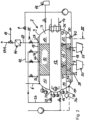
- FIG. 1 shows a perspective view of an example of a reactor 2 for generating water vapor from biogenic mass and/or carbonaceous plastics and for obtaining coal or lignite-like organic material from the supplied starting material of water-containing biogenic mass or carbonaceous plastics.
- the reactor 2 can be used for different purposes, for example for the disposal of complex substances, in particular starting materials that are not homogeneous, for the production of biochar or for use in a gas generating device 1 ( figure 5 ) for the production of hydrogen.
- the reactor 2 is part of a gas generating device, with the steam from the reactor 2 being converted to hydrogen in a steam reformer 64 ( figure 5 ).
- the reactor 2 or the gas generating device 1 has a control unit (not shown).
- the term 'mass to be converted' includes any carbon-based material, including biomass and carbonaceous plastics.
- the reactor 2 has a reactor vessel 3 with a vessel wall 9 which surrounds a filling space 10 of the reactor 2 .
- the reactor vessel 3 can be loaded with mass to be converted, for example a funnel-shaped loading tank 4 for the supply of non-homogeneous starting material to be converted, such as biogenic mass (e.g. animal excrement, wood, sewage sludge) and carbonaceous plastics, is arranged on the reactor 2.
- the mass to be converted is filled into the filling space 10 of the reactor 2 via a filler neck 6 .
- the mass to be converted has a dry matter content TS_g of preferably 5% to 30% (by weight).
- the mass to be converted is to be described Way in a carbonaceous dry substance (coal or lignite-like) converted.
- This dry substance is discharged from the reactor 2 via at least one outlet or outlet nozzle 8 and can then be used for different purposes.
- the dry substance can be used in the further process for the production of synthesis gas with the supply of hydrogen - see below.
- the mass to be converted passes from the loading container 4 into the filling space 10 of the reactor 2 ( 2 ).
- a heating device 14 is assigned to the filling space 10 .
- the heating device is preferably arranged in a heating space 12 or connected to it.
- the heating space 12 is located within the plenum 10 or is thermally connected to a wall of the plenum.
- the heating space 12 extends inside the filling space 10 (preferably in the longitudinal direction of the filling space), so that the heating space emits the thermal heat into the filling space 10 on its outer circumference.
- the heating chamber 12 is designed to heat the mass to be converted and to boil the water contained in the mass to be converted.
- the steam can be generated in the boiler room 12 itself or can be transported into the boiler room 12 from the outside.
- the steam is generated in the boiler room 12 in that the heating device 14 coupled to the boiler room 12 feeds thermal energy into the boiler room 12 and water is fed into the boiler room 12 via a line inlet 16 .
- the water is provided in a suitable water tank, for example, preheated in a water circuit and transported to the line inlet 16 .
- the heating device 14 is or has an electric heater and/or the required heating power can be set or regulated as required. Instead of electric heating, firing can also be carried out, for example by means of gas.
- the heater may be at one end of the boiler room 12, as shown, within the boiler room, or connected to the boiler room via a circulation system, in the latter case the water vapor being generated externally and introduced into the boiler room.
- a circulation system in the latter case the water vapor being generated externally and introduced into the boiler room.
- the boiler room or the walls of the boiler room can also be heated directly with the heating device 12 .
- the boiler room is preferably heated with steam, because then hot steam, which is present as a waste product elsewhere in the overall process, can also be supplied.
- the supplied water is heated, for example, at 16 bar to 25 bar to 203° C. to 225° C. and kept at this temperature by means of the heating device 14 in order to expel the water from the mass to be converted.
- the filling space 10 is preferably surrounded by a thermal jacket 18 which is used for additional heating of the filling space 10 .
- the mass to be converted can be heated in the reactor 2 exclusively via the thermal jacket.
- the thermal jacket preferably also acts to thermally insulate the interior of the reactor from the environment surrounding the reactor.
- the thermal jacket 18 can also be provided exclusively for thermal insulation of the reactor.
- thermal energy or steam is introduced into the thermal jacket.
- steam is supplied via a connecting line from the boiler room 12 by the steam being generated or supplied for internal heating.
- the steam is supplied in such a way that the heating chamber 12 delivers steam to the thermal jacket 18 via a line outlet 20 , a control valve 22 , a connecting line 24 and at least one line inlet 26 of the thermal jacket 18 .
- steam can be fed into the thermal jacket 18 as required if the heat output of the heating chamber 12 is not sufficient and the area for heating the biomass is to be increased.
- steam that is generated in the heating chamber 12 or that is supplied to the heating chamber can be introduced into the filling chamber 10 for the direct heating of the mass to be converted and for the introduction of water in the form of steam, for example to accelerate the heating or in the event of premature exhaustion of the Steam generation from the mass to be converted to provide steam.
- condensate and/or steam can be routed from the thermal jacket 18 into the filling space 10 .
- a jacket outlet 40 of the thermal jacket 18 is connected to a line inlet 44 of the filling chamber 10 via a connecting line 42 .
- a line inlet 17 can optionally be provided for introducing water into the filling space 10 .
- the line input 17 is then preferably connected to the same water tank or to the same water source as the line input 16 of the boiler room 12.
- Process steam is produced in the filling space 10 during the course of the process that is still to be described. This is at least partially discharged from a steam outlet 28 of the filling chamber 10 and, for example, passed on to a steam reformer for the production of hydrogen.
- a pressure adjustment device 29 is preferably arranged at the steam outlet 28, with which the outlet of the steam 69 can be set or regulated in such a way that the water vapor, when a predetermined pressure value is reached in the filling chamber 10 is omitted, for example when the working pressure p_a described below is reached (eg 10 bar).
- an agitator 32 that can be moved via a rotary axis 30 is arranged.
- the agitator can be driven in rotation, for example, via an external motor unit 34 .
- a plurality of paddle-like stirring arms 36 are arranged on the axis of rotation 32 . These are dimensioned in such a way that any sticking or caking of the mass to be converted on the inner wall of the filling space 10 is avoided.
- the mixing action of the rotating agitator 32 promotes rapid and efficient heat transfer within the mass to be converted.
- the agitator 32 can ensure that the mass to be converted is continuously mixed, thereby avoiding any formation of agglomerates.
- the filling chamber 10 is fluidically connected in its lower area to a drain connector 38 . Residual water pressed out of the mass to be converted in the filling space 10 can be drained off via this drain connection 38 . As an alternative or in addition, the residual water can be drained off via the outlet socket or sockets 8 .
- In 4 shows the sequence of the method with regard to the drying of the mass to be converted or with regard to the generation of steam from the mass to be converted.
- the mass to be converted is carbonized in the absence of oxygen (hydrothermal carbonization), but the temperature and pressure are adjusted in such a way that no pyrolysis or gasification of the biogenic mass and/or carbon-containing plastics takes place.
- the procedure can be divided into three phases Ph_1, Ph_2 and Ph_3.
- the first phase Ph_1 preferably runs for a period of 0 to 15 minutes, for example.
- the heating chamber 12 and/or the thermal jacket 18 and/or a direct supply of steam into the filling chamber 10 via its line inlet 44 are used for heating. Since there is a closed atmosphere in the filling space 10, the pressure in the filling space 10 increases due to the generation of steam.
- the filling space 10 is heated immediately after the mass to be converted has been filled in; in particular, it is not evacuated before heating, so that the filling space 10 can be brought to the desired working pressure and working temperature quickly and (energy) efficiently.
- the working temperature T_a is selected in such a way that no pyrolysis takes place in the mass to be converted and instead the water is efficiently expelled and the organic material efficiently can be unlocked. Essentially, the entire reaction takes place with the release of energy (exothermic) and only requires the supply of activation energy to be triggered. A residual moisture remains during the conversion of the mass to be converted into dry substance.
- the working temperature T_a is preferably in the range from 160 to 220°C, preferably from 170 to 200°C, from 175 to 190°C and particularly preferably at approximately 180°C, 183°C or 185°C.
- this pressure (and preferably the temperature T_a of 183° C.) is maintained by releasing steam from the steam outlet 28 for a working time ⁇ t_a of 120 minutes, for example (phase Ph_2). It is preferably only heated via the thermal jacket 18 and steam is produced in the filling space 10 .
- the working pressure p_a is maintained at least while maintaining a predetermined maximum pressure deviation p_ab-max.
- the maximum pressure deviation p_ab-max is, e.g. ⁇ 1 bar or ⁇ 0.5 bar, so that the working pressure p_a in phase Ph_2 can fluctuate between 10 bar and 9 bar or between 9.5 and 10.5 bar.
- the converted mass (based on biogenic mass and/or carbon-containing plastics) is present as a carbon-like dry substance.
- phase Ph_3 filling space 10 is evacuated to a predetermined operating pressure p_b.
- the predetermined operating pressure p_b is preferably in a range from -0.5 bar to -1 bar, is in particular -0.75 bar, ie below atmospheric pressure. In absolute terms, the operating pressure p_b after evacuation is therefore in a range from 0.5 to 0 bar, preferably 0.25 bar.
- the mass or dry substance to be converted is brought to or maintained at a holding temperature T_h (e.g. 75° C.), as a result of which more water can evaporate in the filling space 10 .
- T_h e.g. 75° C.
- This vapor is drawn off via the vapor outlet 28 and preferably cleaned via a filter unit 46 before it is fed into a condenser 47 (preferably with integrated cooling; water temperature, e.g. ⁇ 60° C.) as waste vapor 69-A.
- the condensate produced in this way is preferably fed back to the reactor 2 as water during the method or process, in that it is first conducted to a water tank 53 and then released as water to a heat exchanger 82 as required. There, the water is heated by the cooling of the hydrogen.
- the resulting heated water or water vapor is then fed back to the line inputs 16 and/or 17 as required.
- a closed circuit is provided in the gas generating device 1 in this respect. No steam or any other emissions escape from the gas generating device 1 to the outside. The gas generating device 1 is therefore emission-free.
- the evacuated filling space 10 is filled up again to atmospheric pressure by means of a gas from an external gas pressure device 48 or gas source.
- the supplied gas from the gas source is, for example, CO, CO 2 , N 2 - alternatively, the filling space 10 is flooded with ambient air to atmospheric pressure.
- the dry substance is transported into one or both existing substance containers 50, 51 as required ( figure 5 ), which are each connected to one of the two outlet ports 8.
- the agitator 34 supports the transport of the dry substance produced from the filling space 10 into the substance container 50, 51.
- a lock or a valve 11 is arranged on the outlet connection 8, so that the passage between the filling space 10 and the substance container 50, 51 can be opened to remove the dry substance and is preferably closed during at least the initial drying process (for example during phases Ph_1 and/or Ph_2).
- a closure element (not shown) provided with which or with which the passage between filling space 10 and substance container 50, 51 is / are closed and / which are to be opened for dispensing the dry substance from the reactor to the / the containers 50, 51.
- the closing element is, for example, a slide on the outlet nozzle 8. The opening takes place after the water has evaporated from the mass to be converted and the closing element(s) are/are closed during the evaporation. Due to the orientation and position of the stirring arms 36 or scrapers, the agitator preferably acts in such a way that the dry substance is conveyed along the inside of the container wall 9 in the direction of the outlet 8 .
- the agitator 34 is operated continuously or repeatedly at intervals during the steam generation (preferably during the phases Ph_1, Ph_2 and Ph_3). This improves heat exchange and water vapor release.
- the mechanical action on the mass to be converted causes comminution and prevention of agglomeration, resulting in a homogeneous and small-grained dry substance.
- the outer edges of the agitator arms 36 of the agitator 34 are preferably only a few millimeters or centimeters away from the inner wall when an agitator arm 36 comes closest to an inner wall of the filling space 10, so that a (pre-)grinding effect occurs.
- the agitator 34 acts as a 'scraper' and/or a 'chopper' which is driven by the motor unit 34 of the agitator.
- a chopper 58 (not shown) is arranged in the filling space 10, which is driven by a drive unit (not shown).
- the mass to be converted is converted via the process flow into a dry substance in the form of granular biochar with a fine grain size (e.g. 1 mm to 4 mm) and with a dry substance content TS_g of at least 50%, particularly advantageously at least 85%. and in particular at least 90% (expressed as a percentage by weight in relation to the total mass of dry matter still containing residual moisture).
- a dry substance content TS_g of at least 50%, particularly advantageously at least 85%. and in particular at least 90% (expressed as a percentage by weight in relation to the total mass of dry matter still containing residual moisture).
- Dry substance which has already been converted is preferably additionally introduced into the filling space 10 before, after or together with the filling of mass to be converted (biogenic mass/plastics). This is advantageous in the conversion of sewage sludge provided with binders, for example, since the binders would impede the conversion process in the reactor 2 .
- the coal-like dry substance binds the binder mixed with the sewage sludge so that the binder can no longer impair the further conversion process of the starting material.
- At least one of the substance containers 50, 51 can have an additional heating device (not shown) in order to heat up and further dry the dry substance collected in the container.
- FIG 5 shows the use of the reactor 2 in a gas generating device 1 for the production of hydrogen.
- the mass to be converted is filled into the container 4 via an inlet 52 for liquid substances and/or an inlet 54 for solids.
- the container 4 has, for example, a capacity of 20 liters (experimental reactors) to 20,000 liters, preferably 300 to 4,000 liters, more preferably 500 to 1,500 liters.
- the container 4 has an input 56 for a pH value adjusting agent (eg citric acid) for adjusting the pH value of the filled mass to be converted.
- a pH value adjusting agent eg citric acid
- the pH value is preferably adjusted by the agent in such a way that the mass to be converted remains in the acidic environment, preferably the pH value of the mass to be converted is adjusted to a value in the range from 3 to 5.
- At least one substance container 50, 51 is provided in the gas generating device 1 as a storage container for the dry substance or biochar in order to produce a synthesis gas 62 via further method steps to be described, which is fed to a steam reformer 64.
- the second substance container 51 preferably also serves as a cleaning unit 66 for cleaning the process steam 69 which is drawn off from the filling space 10 via the steam outlet 28 and fed to the steam reformer 64 .
- at least part of the water vapor from the process vapor outlet 28 is fed to the substance container 51 via a connecting line 69a.
- the substance container 51 has a perforated sieve bottom 68 via which the supplied process steam 69 is conducted into the substance container 51 for cleaning and flows evenly through the dry substance.
- the process steam 69 is cleaned in a cleaning unit 66 which is arranged separately from the reactor 2 and in which the dry substance optionally also acts as a filter substrate.
- the cleaning unit 66 is dispensed with and the process steam 69 is fed directly to the steam reformer 64 .
- the dry substance from the substance container 51 or from the cleaning unit 66 can be burned after being used for steam cleaning and used in this way to generate energy for generating steam for the reactor 2 .
- a significant energy saving can be achieved in the overall process.
- the dry substance of the substance container 50 (and optionally of the substance container 51) is first transported by means of a first conveyor unit 71a to a grinding unit 70 (e.g. via a screw conveyor) in order to be (further) comminuted there.
- a grinding unit 70 e.g. via a screw conveyor
- the dry substance is ground into granules (e.g. 0.1 mm particle size) or into pulverized coal to make them suitable for a gas environment.
- the ground dry substance is fed to a reactor unit 72 (synthetic gas generating device) by means of a second conveyor unit 71b.
- the first and second conveying unit 71a, 71b form a conveying device which feeds the carbon-containing dry substance from the reactor 2 or from the substance container(s) to the reactor unit 72.
- the reactor unit 72 is or acts in particular in the manner of an entrained flow gasifier or in the manner of the Koppers-Totzek process.
- the ground dry substance is blown in by means of a pressure source 74 (preferably by a gas flow of steam and/or oxygen), e.g. at 40 bar. If oxygen is provided by the pressure source 74, it can be obtained, for example, by means of electrolysis.
- a high temperature in particular at 700°C to 1100°C or at 1600°C to 1800°C or at 1400 to 1800°C
- the ground dry substance is gasified in a flue dust flame within just a few seconds.
- a water supply 76 e.g. quench water
- the ash produced in the water bath can be disposed of as slag.
- the water bath can also be used as a gas barrier for reactive gases.
- the reactor unit 72 can also cooperate with an integrated or external heat exchanger to cool the synthesis gas 62 (eg to 900°C to 950°C) before it is fed to a cleaning stage 78 .
- the waste heat from the synthesis gas 62 can For example, heat a thermal oil, which is optionally used for heating the steam reformer 64 (eg via a thermal jacket).
- the synthesis gas 62 is cleaned, for example at 900° C. to 950° C. and at 25 bar.
- the cleaning stage 78 can be a gas scrubber or can have a gas scrubber. Unwanted components (e.g. sulphur) are thereby separated.
- the synthesis gas 62 supplied to the steam reformer 64 has, for example, a gas composition of H 2 (33% by volume), CO (60% by volume), CO 2 (6% by volume) and other gases (1% by volume).
- the synthesis gas 62 is preferably fed to the steam reformer 64 at a pressure of 40 bar.
- process steam is discharged from reactor 2 in phase Ph_2.
- This process steam 69 is conducted to the steam reformer 64 at its working temperature T_a (eg 183° C.) and a working pressure p_a (eg 10 bar).
- the process steam 69 is heated there. This heating is preferably carried out in the so-called batch mode up to 354.6°C.
- the steam reforming preferably takes place in batch mode at 354.6° C. using a Ni catalyst and with supercritical steam at 221 bar.
- a hydrogen gas 80 with a high degree of purity (preferably about 80% by volume) is available.
- the hydrogen gas 80 is optionally supplied to the exhaust steam generator or heat exchanger 82 before being routed to a gas cooling unit 84 .
- the optionally interposed heat exchanger 82 has the advantage that the hydrogen gas 80 can heat up water there, which has to be fed to the reactor 2 anyway, e.g. via its line inlet 16.
- the hydrogen gas 80 is (further) cooled down (e.g. from 250°C to 75°C).
- the cooled hydrogen gas 80 is fed to a cleaning unit 86 .
- hydrogen is separated from the remaining components of the hydrogen gas 80 .
- the cleaning unit 86 preferably contains a specific membrane filter.
- Hydrogen 88 and a residual gas mixture 90 are separated and fed to various storage devices or directly connected consumers and/or further processing stages.
- the reactor 2 can have at least one charging device 100, 100' connected to the filling space 10 for charging the reactor vessel 3 or the filling space 10 and/or for pretreating the mass to be converted.
- a loading container 4 is provided, which optionally has a comminuting device for comminuting or homogenizing the mass to be converted supplied by the charging device (eg chopper, grinder).
- the starting material pretreated in this way can then be introduced into the reactor vessel 3 as described above.
- an alternative or additional loading device 100' (in figure 5 shown in dashed lines) for the pre-treatment of the biogenic mass and plastics to be converted.
- the charging device has at least one pre-treatment container 102 with at least one inlet 52, 54 for the mass to be converted, as described above.
- This charging device 100' can also have a comminuting device for comminuting/homogenizing the mass to be converted supplied by the charging device 100'.
- a pH adjustment device 106 connected to the treatment tank 102 is provided for adjusting a desired pH of the mass to be converted. The pH value of the mass to be converted in the treatment tank 102 is adjusted in such a way that substances such as heavy metals, sulfur and/or phosphorus are dissolved out of the mass to be converted.
- a further heating device 104 is preferably provided for heating the mass to be converted contained in the treatment container 102, so that the mass to be converted gives off water in the form of water vapor as a result of the heating (drying).
- a cleaning device 108 connected to the treatment container 102 is designed to withdraw liquid from the treatment container (e.g. by means of a pump), to clean the liquid that has been drawn off and to feed the cleaned liquid to the treatment container (4, 102) and/or the filling space (10).
- At least two reactors 2 as described above are provided, with a steam outlet 28 for discharging steam from the filling space 10 of a (first) reactor 2 being connected to a heating space of a heating device for heating up a filling space of a subsequent (second) reactor (not shown).
- the vapor outlet 28 of the first reactor can be connected to the fill space and/or a thermal jacket of the second reactor.
- the (exothermic) conversion process in the first reactor 2 can first be initialized and then the energy released in the process can be used to initialize the conversion process in the second reactor, with the energy being transported by means of the steam generated.
- more than two reactors can be provided on are connected to one another (in a cascade fashion) in this way, so that the steam produced can be shifted between the reactors and/or the steam reformer 64 described above as required.
Landscapes
- Chemical & Material Sciences (AREA)
- Engineering & Computer Science (AREA)
- Chemical Kinetics & Catalysis (AREA)
- Oil, Petroleum & Natural Gas (AREA)
- Organic Chemistry (AREA)
- Combustion & Propulsion (AREA)
- Life Sciences & Earth Sciences (AREA)
- Mechanical Engineering (AREA)
- General Engineering & Computer Science (AREA)
- General Chemical & Material Sciences (AREA)
- Wood Science & Technology (AREA)
- Microbiology (AREA)
- Physics & Mathematics (AREA)
- Thermal Sciences (AREA)
- Health & Medical Sciences (AREA)
- General Health & Medical Sciences (AREA)
- Inorganic Chemistry (AREA)
- Processing Of Solid Wastes (AREA)
- Feeding, Discharge, Calcimining, Fusing, And Gas-Generation Devices (AREA)
- Organic Low-Molecular-Weight Compounds And Preparation Thereof (AREA)
Claims (14)
- Réacteur (2) pour convertir une masse biogène contenant de l'eau et/ou des matières plastiques contenant du carbone en une substance sèche contenant du carbone présentant une teneur en substance sèche (TS_g) d'au moins 85 %, en particulier d'au moins 90 %, et pour générer de la vapeur d'eau, dans lequel le réacteur (2) présente :une unité de commande pour commander le fonctionnement du réacteur,un récipient de réacteur (3) avec une paroi de récipient (9),une chambre de remplissage (10) entourée par la paroi de récipient (9) pour recevoir la masse à convertir,un agitateur (32) disposé à l'intérieur de l'espace de remplissage (10),un dispositif de chauffage (12, 18) pour chauffer la masse à convertir reçue dans la chambre de remplissage (10), de sorte que la masse à convertir libère de l'eau sous forme de vapeur d'eau (séchage) en raison du chauffage dans la chambre de remplissage (10), dans lequel le dispositif de chauffage (12, 18) présente une chambre de chauffage (12) qui est disposée à l'intérieur de la chambre de remplissage (10), de sorte que la chambre de chauffage (12) libère la chaleur de chauffage dans la chambre de remplissage (10) sur sa périphérie extérieure,une sortie de vapeur (28) pour évacuer la vapeur d'eau, etau moins un récipient de substance (50, 51) pour recevoir la substance sèche, dans lequel le au moins un récipient de substance est relié à la chambre de remplissage (10) par une sortie (8) au niveau de la paroi de récipient (9),dans lequel l'agitateur (32) est conçu pour empêcher l'agrégation ou la solidification de la masse sèche dans la chambre de remplissage (10) pendant le séchage,caractérisé en ce quela chambre de chauffage (12) présente une entrée de conduite (16) pour l'introduction d'eau et/ou de vapeur d'eau, de sorte que de la vapeur peut être générée dans la chambre de chauffage (12) elle-même et/ou transportée depuis l'extérieur jusque dans la chambre de chauffage (12) pour la fonction de chauffage, etpour alimenter la chambre de remplissage (10) en vapeur, une entrée de conduite de la chambre de remplissage (10) est reliée de manière pouvant être interrompue à une sortie de conduite de la chambre de chauffage (12).
- Réacteur selon la revendication 1, dans lequel l'agitateur (32) est conçu pour faire circuler la masse à convertir pendant le séchage de la masse à convertir, et/ou
dans lequel l'agitateur (32) est conçu pour transporter la substance sèche dans la direction de la sortie après le séchage, de sorte que la substance sèche est transportée à l'extérieur de la chambre de remplissage (10) jusque dans le au moins un récipient de substance (50, 51). - Réacteur selon la revendication 1 ou 2, dans lequel au moins une partie de la vapeur d'eau évacuée de la sortie de vapeur (28) est amenée au récipient de substance (50, 51) par l'intermédiaire d'une conduite de liaison (69a), où la vapeur d'eau est purifiée lors du passage à travers la substance sèche stockée dans le récipient de substance (50, 51), en particulier dans lequel au moins un récipient de substance (50, 51) présente un dispositif de chauffage pour le chauffage ou le séchage de la substance sèche reçue dans le récipient de substance, et/ou
au moins une partie de la vapeur d'eau évacuée de la sortie de vapeur (28) est amenée à un réacteur supplémentaire par l'intermédiaire d'une conduite de liaison supplémentaire, en particulier est amenée à un dispositif de chauffage pour chauffer la masse à convertir reçue dans une chambre de remplissage (10) d'un réacteur supplémentaire et/ou est amenée à une chambre de remplissage (10) d'un réacteur supplémentaire. - Réacteur selon l'une quelconque des revendications précédentes, dans lequel la température et de préférence la pression dans la chambre de remplissage (10) peuvent être ajustées au moyen du dispositif de chauffage (12, 18) de telle sorte que pendant la conversion de la masse à convertir, il n'y a pas ou pratiquement pas de gazéification (pyrolyse) de la masse biogène et/ou des matières plastiques à base de carbone.
- Réacteur selon l'une quelconque des revendications précédentes, dans lequel un dispositif d'ajustement de pression (29) est agencé au niveau de la sortie de vapeur (28), au moyen duquel la vapeur d'eau peut être évacuée de la sortie de vapeur (28) lorsqu'une pression de travail prédéterminée (p_a) est atteinte et/ou lorsqu'une température de travail prédéterminée (T_a) est atteinte.
- Utilisation d'un réacteur selon l'une quelconque des revendications précédentes dans un dispositif générateur de gaz (1) pour produire de l'hydrogène, ledit dispositif générateur de gaz comprenant :au moins un réacteur (2) selon l'une des revendications précédentes pour la génération de vapeur d'eau, dans lequel une chambre de chauffage (12) du réacteur (2) présente une entrée de conduite (16) pour l'introduction d'eau et/ou de vapeur d'eau, de sorte que pour la fonction de chauffage, de la vapeur peut être générée dans la chambre de chauffage (12) elle-même et/ou peut être transportée depuis l'extérieur jusque dans la chambre de chauffage (12), et dans lequel pour l'alimentation en vapeur d'une chambre de remplissage (10) du réacteur (2), une entrée de conduite de la chambre de remplissage (10) est reliée de manière pouvant être interrompue à une sortie de conduite de la chambre de chauffage (12),un dispositif générateur de gaz de synthèse (72) pour générer du gaz de synthèse, etun reformeur à vapeur (64) qui est conçu pour générer de l'hydrogène à partir de vapeur d'eau et de gaz de synthèse, dans lequel la vapeur d'eau est fournie au reformeur à vapeur (64) par l'intermédiaire d'une première conduite de connexion (69) depuis le réacteur (2) et le gaz de synthèse est fourni depuis le dispositif générateur de gaz de synthèse (72) par l'intermédiaire d'une seconde conduite de connexion (62).
- Utilisation dans un dispositif de génération de gaz selon la revendication 6, dans laquelle un dispositif de transport (71a-b) relie le récipient de substance (50, 51) au dispositif générateur de gaz de synthèse (72) et est conçu pour transporter la substance sèche vers le dispositif générateur de gaz de synthèse (72).
- Utilisation dans un dispositif générateur de gaz selon la revendication 6 ou 7, dans laquelle une unité de broyage (70) est prévue, qui broyé la substance sèche à l'extérieur du récipient de substance (50, 51) de telle sorte que la substance sèche broyée puisse être amenée au dispositif générateur de gaz de synthèse (72) sous forme de particules broyées, en particulier sous forme de granulés et/ou de poussière, dans laquelle le dispositif de transport (71a-b) présente en particulier une première unité de transport (71a) pour transporter la substance sèche depuis le récipient de substance (50, 51) vers l'unité de broyage (70) et/ou une seconde unité de transport (71b) pour transporter la substance sèche broyée depuis l'unité de broyage (70) vers le dispositif générateur de gaz de synthèse (72).
- Utilisation dans un dispositif générateur de gaz selon l'une quelconque des revendications 6, 7 ou 8, avec au moins deux réacteurs (2), dans laquelle une sortie de vapeur (28) pour évacuer la vapeur d'eau à partir de la chambre de remplissage (10) d'un réacteur (2) est reliée à une chambre de chauffage (12) d'un dispositif de chauffage (12, 18) pour chauffer une chambre de remplissage (10) d'un réacteur suivant (2) et/ou est reliée à une chambre de remplissage (10) d'un réacteur suivant (2).
- Procédé de conversion d'une masse biogène contenant de l'eau et/ou de matières plastiques contenant du carbone en une substance sèche contenant du carbone présentant une teneur en substance sèche (TS_g) d'au moins 85 %, en particulier d'au moins 90%, et de génération de vapeur d'eau, en particulier avec un réacteur (2) selon l'une quelconque des revendications précédentes 1 à 5, le procédé comprenant les étapes consistant à :remplir une chambre de remplissage (10) d'un réacteur (2) avec la masse à convertir, dans lequel en particulier avant, après ou en même temps que le remplissage de la chambre de remplissage (10) avec la masse à convertir, de la substance sèche contenant du carbone supplémentaire est introduite dans la chambre de remplissage (10),chauffer la masse à convertir dans la chambre de remplissage (10) à une température de travail (T_a) ou à une plage de température de travail prédéterminée et ajuster une pression de travail (p_a) ou une plage de pression de travail prédéterminée, dans lequel de la vapeur est générée dans la chambre de chauffage (12) du dispositif de chauffage (12, 18) et/ou transportée depuis l'extérieur jusque dans la chambre de chauffage (12) pour la fonction de chauffage, et dans lequel la chambre de remplissage (10) est alimentée en vapeur à partir de la chambre de chauffage (12),évacuer la vapeur de processus (69) à partir de la chambre de remplissage (10) tout en maintenant la température à la température de travail prédéterminée ou dans la plage de température de travail prédéterminée et en maintenant la pression à la pression de travail prédéterminée ou dans la plage de pression de travail prédéterminée,pendant la conversion de la masse à convertir, mélanger et/ou mettre en circulation de manière temporaire ou continue la masse à convertir dans l'espace de remplissage, de préférence au moyen d'un agitateur (32) et/ou d'un broyeur disposé à l'intérieur de l'espace de remplissage (10).
- Procédé selon la revendication 10, dans lequel la température à la température de travail prédéterminée (T_a) ou dans la plage de température de travail prédéterminée et/ou la pression à la pression de travail prédéterminée (p_a) ou dans la plage de pression de travail prédéterminée sont maintenues pendant une durée de travail prédéterminée (Δt_a), et dans lequel en particulier :après la fin de la durée de travail (Δt_a), la chambre de remplissage (10) est évacuée à une pression de service prédéterminée (p_b), etpendant l'évacuation de la chambre de remplissage (10), de l'eau sous forme de vapeur d'eau est extraite de la chambre de remplissage (10) de la pression de travail (p_a) à la pression de service (p_b) et, de préférence, une température de maintien prédéterminée (T_h) de la masse à convertir est maintenue au moins temporairement lorsque la pression de service (p_b) est ajustée.
- Procédé selon la revendication 11,dans lequel la vapeur de processus (69) évacuée de la chambre de remplissage (10) est amenée à un reformeur à vapeur (64) pour générer de l'hydrogène (80, 88), et/oudans lequel la substance sèche (51) convertie dans le réacteur (2) à partir de la masse à convertir est amenée vers un dispositif générateur de gaz de synthèse (72) pour générer du gaz de synthèse (62), dans lequel le gaz de synthèse généré est amené de préférence vers un reformeur à vapeur (64) pour générer de l'hydrogène (80, 88).
- Procédé selon l'une quelconque des revendications 11 à 12,dans lequel la température de travail (T_a) est dans une plage de 170°C à 250°C, en particulier de 183°C, et/oudans lequel la pression de travail (p_a) se situe dans une plage de 8 bar à 20 bar, en particulier de 10 bar à 11 bar, et/oudans lequel la durée du travail (Δt_a) est de 1,50 à 6 heures, en particulier de 2 heures, et/oudans lequel la température de maintien prédéterminée (T_h) de la chambre de remplissage évacuée (10) est comprise entre 50°C et 100°C, en particulier de 75°C, et/oudans lequel la masse à convertir présente, après la fin de l'évacuation de l'espace de remplissage (10), une teneur en substance sèche (TS_g) d'au moins 50 %, en particulier d'au moins 85 %.
- Procédé selon l'une quelconque des revendications précédentes 11 à 13, dans lequel le procédé comprend les étapes suivantes avant le remplissage d'un espace de remplissage (10) d'un réacteur (2) par une masse à convertir :un remplissage d'un récipient de prétraitement (102) par la masse à convertir,un ajustement d'une valeur de pH souhaitée de la masse à convertir pour séparer des substances telles que les métaux lourds à partir de la masse à convertir, etun retrait du liquide contenant les substances dissoutes à partir du récipient de traitement (102), une purification du liquide retiré et une introduction du liquide purifié dans le récipient de traitement (102) et/ou dans l'espace de remplissage (10) du réacteur,en particulier, le chauffage de la masse dans le récipient de traitement (102) à une température de prétraitement prédéterminée ou à une plage de température de prétraitement prédéterminée et l'ajustement d'une pression de prétraitement prédéterminée ou d'une plage de pression de prétraitement avant ou après l'ajustement de la valeur de pH souhaitée.
Applications Claiming Priority (1)
| Application Number | Priority Date | Filing Date | Title |
|---|---|---|---|
| DE102019114060.9A DE102019114060A1 (de) | 2019-05-27 | 2019-05-27 | Reaktor zur erzeugung von wasserdampf und trockensubstanz, gaserzeugungsvorrichtung und verfahren zur dampf und gaserzeugung |
Publications (4)
| Publication Number | Publication Date |
|---|---|
| EP3745065A2 EP3745065A2 (fr) | 2020-12-02 |
| EP3745065A3 EP3745065A3 (fr) | 2021-03-03 |
| EP3745065C0 EP3745065C0 (fr) | 2023-06-07 |
| EP3745065B1 true EP3745065B1 (fr) | 2023-06-07 |
Family
ID=70617061
Family Applications (1)
| Application Number | Title | Priority Date | Filing Date |
|---|---|---|---|
| EP20401026.8A Active EP3745065B1 (fr) | 2019-05-27 | 2020-05-02 | Réacteur de production de vapeur d'eau et de substance sèche |
Country Status (5)
| Country | Link |
|---|---|
| EP (1) | EP3745065B1 (fr) |
| DE (1) | DE102019114060A1 (fr) |
| ES (1) | ES2951950T3 (fr) |
| HU (1) | HUE062807T2 (fr) |
| PL (1) | PL3745065T3 (fr) |
Families Citing this family (2)
| Publication number | Priority date | Publication date | Assignee | Title |
|---|---|---|---|---|
| DE102021002921A1 (de) | 2021-06-08 | 2022-12-08 | Fritz Curtius | Messvorrichtung für Ammoniak NH3 in Klärschlamm und in biotischer Biomasse |
| DE202021001992U1 (de) | 2021-06-08 | 2021-10-04 | Fritz Curtius | Messvorrichtung für Ammoniak NH3 in Klärschlamm und in biotischer Biomasse |
Family Cites Families (13)
| Publication number | Priority date | Publication date | Assignee | Title |
|---|---|---|---|---|
| CA1225062A (fr) * | 1983-09-13 | 1987-08-04 | Trevor R. Bridle | Appareil et methode pour la transformation des boues |
| US5426866A (en) * | 1991-06-25 | 1995-06-27 | Lucia Baumann-Schilp | Method and apparatus for dewatering of sludges |
| JPH0947747A (ja) * | 1995-06-01 | 1997-02-18 | Shiiratsuku:Kk | 有機性廃棄物の高速真空乾燥発酵方法及びその装置 |
| DE19608093C2 (de) * | 1996-03-02 | 2000-08-10 | Krc Umwelttechnik Gmbh | Verfahren zur Verwertung von Rest- und Abfallstoffen sowie heizwertarmen Brennstoffen in einem Zementofen |
| ATE287073T1 (de) * | 1999-10-05 | 2005-01-15 | Rubicon Dev Company L L C | Diskontinuierlicher schlammentwässerer |
| CN101448581A (zh) * | 2006-09-28 | 2009-06-03 | Eco原料株式会社 | 有机类废弃物的处理系统 |
| JP2008264756A (ja) * | 2007-03-23 | 2008-11-06 | Kunitomo Kankyo Plant:Kk | 有機廃棄物の処理装置及び処理方法,該処理方法によって得られる有機資材 |
| US7875090B2 (en) * | 2007-04-24 | 2011-01-25 | The United States Of America As Represented By The Secretary Of Agriculture | Method and apparatus to protect synthesis gas via flash pyrolysis and gasification in a molten liquid |
| DE102008006772A1 (de) | 2008-01-30 | 2009-08-06 | Simon Albert Breitbach | Verfahren zur Karbonisierung organischer Substanzen |
| US20140116938A1 (en) * | 2012-10-25 | 2014-05-01 | Marcus George Theodore | Chemical Treatment Method and Apparatus to Increase Wastewater Bioreactor Processing Capacity While Producing Class A Biosolids |
| KR101890952B1 (ko) * | 2012-12-26 | 2018-08-22 | 에스케이이노베이션 주식회사 | 기류 건조기를 포함하는 탄소 연료의 가스화 복합 설비 |
| US10538446B2 (en) * | 2016-10-28 | 2020-01-21 | Rdp Technologies, Inc. | Aerobic thermal chemical hydrolysis process |
| CN208414199U (zh) * | 2018-05-22 | 2019-01-22 | 海若斯(北京)环境科技有限公司 | 一种水蒸气内循环污泥干燥装置 |
-
2019
- 2019-05-27 DE DE102019114060.9A patent/DE102019114060A1/de active Pending
-
2020
- 2020-05-02 HU HUE20401026A patent/HUE062807T2/hu unknown
- 2020-05-02 ES ES20401026T patent/ES2951950T3/es active Active
- 2020-05-02 PL PL20401026.8T patent/PL3745065T3/pl unknown
- 2020-05-02 EP EP20401026.8A patent/EP3745065B1/fr active Active
Also Published As
| Publication number | Publication date |
|---|---|
| EP3745065C0 (fr) | 2023-06-07 |
| EP3745065A2 (fr) | 2020-12-02 |
| DE102019114060A1 (de) | 2020-12-03 |
| PL3745065T3 (pl) | 2023-12-04 |
| EP3745065A3 (fr) | 2021-03-03 |
| HUE062807T2 (hu) | 2023-12-28 |
| ES2951950T3 (es) | 2023-10-25 |
Similar Documents
| Publication | Publication Date | Title |
|---|---|---|
| CH720670A2 (de) | Gerät zur thermischen Karbonisierung von kommunalem Schlamm | |
| DE102008047883B4 (de) | Vorrichtung und Verfahren zur Behandlung von Biomasse | |
| EP2831198B1 (fr) | Dispositif et procédé de dépolymérisation catalytique d'une matière contenant un hydrocarbure | |
| EP0126407B1 (fr) | Procédé pour la récupération d'un gaz utile à partir d'ordures par pyrolyse et dispositif pour la mise en oeuvre du procédé | |
| EP1432535B1 (fr) | Procede permettant de traiter des dechets et installation de traitement | |
| DE102007062810A1 (de) | Anlage zur Erzeugung von Energie aus Biomasse | |
| DE102008006719B4 (de) | Verfahren und Vorrichtung zur Reinigung kontaminierter Materialien | |
| EP2284141A1 (fr) | Procédé et dispositif de fabrication de particules de charbon enrichies avec des matières minérales | |
| DE202013101154U1 (de) | Pyrolyseaggregat für feuchte Biomasse | |
| EP3745065B1 (fr) | Réacteur de production de vapeur d'eau et de substance sèche | |
| DE102007011763B3 (de) | Verfahren zur katalytischen Aufbereitung von Klärschlamm und Einrichtung zur Durchführung des Verfahrens | |
| DE2800030C3 (de) | Verfahren zur Umsetzung von Naßabfall durch Pyrolyse | |
| DE4304294C2 (de) | Verfahren zur Gewinnung verwertbarer Stoffe aus Verbundmaterial | |
| EP1078698B1 (fr) | Procédé et dispositif pour le traitement thermolytique des matières contenant des polymères et de la cellulose, notamment des produits déchiquetés légèrs | |
| DE102010005253B4 (de) | Verfahren und Vorrichtung zum Behandeln und/oder Aufbereiten von flüssigem Gärrest aus einem Nachgärer und/oder Fermenter einer Biogasanlage | |
| EP3581640B1 (fr) | Procédé et dispositif de préparation des substances biologiques, en particulier d'origine végétale et d'origine animale de fermentation, en particulier des installations de biogaz, à partir du lisier ou d'autres produits de déchets organiques | |
| DE102011113825A1 (de) | Zumindest quasi kontinuierliche hydrothermale Karbonisierung von Biomasse | |
| DE3221495A1 (de) | Verfahren und vorrichtung zur konvertierung von klaerschlamm in oel und kohle | |
| WO2020016183A1 (fr) | Procédé et dispositif de production de charbon actif | |
| DE4442100A1 (de) | Verfahren und Anlage zur Aufbereitung von Klärschlamm zu einer Rohmehlkomponente für die Zementherstellung | |
| EP0958332B1 (fr) | Procede et dispositif pour le traitement de materiaux residuaires biologiques, notamment de boues de curage | |
| DE19937188C1 (de) | Verfahren zur Verwertung von Gasen aus dem Absetzbecken | |
| DE60225380T2 (de) | Verfahren und Vorrichtung zur Herstellung von Brenngas aus durch thermische Zersetzung eines Feststoffzusatzes erzeugtem Gas | |
| EP2536495B1 (fr) | Procédé et dispositif pour l'obtention de carburants et gaz combustibles à partir de substances organiques | |
| EP2253693A1 (fr) | Procédé de traitement de matières résiduelles de brasseries |
Legal Events
| Date | Code | Title | Description |
|---|---|---|---|
| PUAI | Public reference made under article 153(3) epc to a published international application that has entered the european phase |
Free format text: ORIGINAL CODE: 0009012 |
|
| STAA | Information on the status of an ep patent application or granted ep patent |
Free format text: STATUS: THE APPLICATION HAS BEEN PUBLISHED |
|
| AK | Designated contracting states |
Kind code of ref document: A2 Designated state(s): AL AT BE BG CH CY CZ DE DK EE ES FI FR GB GR HR HU IE IS IT LI LT LU LV MC MK MT NL NO PL PT RO RS SE SI SK SM TR |
|
| AX | Request for extension of the european patent |
Extension state: BA ME |
|
| PUAL | Search report despatched |
Free format text: ORIGINAL CODE: 0009013 |
|
| AK | Designated contracting states |
Kind code of ref document: A3 Designated state(s): AL AT BE BG CH CY CZ DE DK EE ES FI FR GB GR HR HU IE IS IT LI LT LU LV MC MK MT NL NO PL PT RO RS SE SI SK SM TR |
|
| AX | Request for extension of the european patent |
Extension state: BA ME |
|
| RIC1 | Information provided on ipc code assigned before grant |
Ipc: F26B 3/20 20060101AFI20210126BHEP Ipc: F26B 3/24 20060101ALI20210126BHEP Ipc: C10J 3/46 20060101ALI20210126BHEP Ipc: C10K 3/00 20060101ALI20210126BHEP Ipc: F26B 9/08 20060101ALI20210126BHEP Ipc: C10G 1/02 20060101ALI20210126BHEP |
|
| STAA | Information on the status of an ep patent application or granted ep patent |
Free format text: STATUS: REQUEST FOR EXAMINATION WAS MADE |
|
| 17P | Request for examination filed |
Effective date: 20210819 |
|
| RBV | Designated contracting states (corrected) |
Designated state(s): AL AT BE BG CH CY CZ DE DK EE ES FI FR GB GR HR HU IE IS IT LI LT LU LV MC MK MT NL NO PL PT RO RS SE SI SK SM TR |
|
| STAA | Information on the status of an ep patent application or granted ep patent |
Free format text: STATUS: EXAMINATION IS IN PROGRESS |
|
| 17Q | First examination report despatched |
Effective date: 20211118 |
|
| GRAP | Despatch of communication of intention to grant a patent |
Free format text: ORIGINAL CODE: EPIDOSNIGR1 |
|
| STAA | Information on the status of an ep patent application or granted ep patent |
Free format text: STATUS: GRANT OF PATENT IS INTENDED |
|
| INTG | Intention to grant announced |
Effective date: 20221021 |
|
| GRAS | Grant fee paid |
Free format text: ORIGINAL CODE: EPIDOSNIGR3 |
|
| GRAA | (expected) grant |
Free format text: ORIGINAL CODE: 0009210 |
|
| STAA | Information on the status of an ep patent application or granted ep patent |
Free format text: STATUS: THE PATENT HAS BEEN GRANTED |
|
| AK | Designated contracting states |
Kind code of ref document: B1 Designated state(s): AL AT BE BG CH CY CZ DE DK EE ES FI FR GB GR HR HU IE IS IT LI LT LU LV MC MK MT NL NO PL PT RO RS SE SI SK SM TR |
|
| REG | Reference to a national code |
Ref country code: GB Ref legal event code: FG4D Free format text: NOT ENGLISH |
|
| REG | Reference to a national code |
Ref country code: CH Ref legal event code: EP Ref country code: AT Ref legal event code: REF Ref document number: 1576251 Country of ref document: AT Kind code of ref document: T Effective date: 20230615 |
|
| REG | Reference to a national code |
Ref country code: DE Ref legal event code: R096 Ref document number: 502020003607 Country of ref document: DE |
|
| U01 | Request for unitary effect filed |
Effective date: 20230607 |
|
| U07 | Unitary effect registered |
Designated state(s): AT BE BG DE DK EE FI FR IT LT LU LV MT NL PT SE SI Effective date: 20230615 |
|
| REG | Reference to a national code |
Ref country code: NO Ref legal event code: T2 Effective date: 20230607 |
|
| REG | Reference to a national code |
Ref country code: LT Ref legal event code: MG9D |
|
| REG | Reference to a national code |
Ref country code: ES Ref legal event code: FG2A Ref document number: 2951950 Country of ref document: ES Kind code of ref document: T3 Effective date: 20231025 |
|
| PG25 | Lapsed in a contracting state [announced via postgrant information from national office to epo] |
Ref country code: RS Free format text: LAPSE BECAUSE OF FAILURE TO SUBMIT A TRANSLATION OF THE DESCRIPTION OR TO PAY THE FEE WITHIN THE PRESCRIBED TIME-LIMIT Effective date: 20230607 Ref country code: HR Free format text: LAPSE BECAUSE OF FAILURE TO SUBMIT A TRANSLATION OF THE DESCRIPTION OR TO PAY THE FEE WITHIN THE PRESCRIBED TIME-LIMIT Effective date: 20230607 Ref country code: GR Free format text: LAPSE BECAUSE OF FAILURE TO SUBMIT A TRANSLATION OF THE DESCRIPTION OR TO PAY THE FEE WITHIN THE PRESCRIBED TIME-LIMIT Effective date: 20230908 |
|
| REG | Reference to a national code |
Ref country code: HU Ref legal event code: AG4A Ref document number: E062807 Country of ref document: HU |
|
| PG25 | Lapsed in a contracting state [announced via postgrant information from national office to epo] |
Ref country code: SK Free format text: LAPSE BECAUSE OF FAILURE TO SUBMIT A TRANSLATION OF THE DESCRIPTION OR TO PAY THE FEE WITHIN THE PRESCRIBED TIME-LIMIT Effective date: 20230607 |
|
| PG25 | Lapsed in a contracting state [announced via postgrant information from national office to epo] |
Ref country code: IS Free format text: LAPSE BECAUSE OF FAILURE TO SUBMIT A TRANSLATION OF THE DESCRIPTION OR TO PAY THE FEE WITHIN THE PRESCRIBED TIME-LIMIT Effective date: 20231007 |
|
| PG25 | Lapsed in a contracting state [announced via postgrant information from national office to epo] |
Ref country code: SM Free format text: LAPSE BECAUSE OF FAILURE TO SUBMIT A TRANSLATION OF THE DESCRIPTION OR TO PAY THE FEE WITHIN THE PRESCRIBED TIME-LIMIT Effective date: 20230607 Ref country code: SK Free format text: LAPSE BECAUSE OF FAILURE TO SUBMIT A TRANSLATION OF THE DESCRIPTION OR TO PAY THE FEE WITHIN THE PRESCRIBED TIME-LIMIT Effective date: 20230607 Ref country code: RO Free format text: LAPSE BECAUSE OF FAILURE TO SUBMIT A TRANSLATION OF THE DESCRIPTION OR TO PAY THE FEE WITHIN THE PRESCRIBED TIME-LIMIT Effective date: 20230607 Ref country code: IS Free format text: LAPSE BECAUSE OF FAILURE TO SUBMIT A TRANSLATION OF THE DESCRIPTION OR TO PAY THE FEE WITHIN THE PRESCRIBED TIME-LIMIT Effective date: 20231007 |
|
| REG | Reference to a national code |
Ref country code: DE Ref legal event code: R097 Ref document number: 502020003607 Country of ref document: DE |
|
| RAP2 | Party data changed (patent owner data changed or rights of a patent transferred) |
Owner name: HOLZNER DRUCKBEHAELTER GMBH |
|
| U1K | Transfer of rights of the unitary patent after the registration of the unitary effect |
Owner name: HOLZNER DRUCKBEHAELTER GMBH; DE |
|
| U20 | Renewal fee for the european patent with unitary effect paid |
Year of fee payment: 5 Effective date: 20240304 |
|
| PLBE | No opposition filed within time limit |
Free format text: ORIGINAL CODE: 0009261 |
|
| STAA | Information on the status of an ep patent application or granted ep patent |
Free format text: STATUS: NO OPPOSITION FILED WITHIN TIME LIMIT |
|
| 26N | No opposition filed |
Effective date: 20240308 |
|
| REG | Reference to a national code |
Ref country code: HU Ref legal event code: GB9C Owner name: HOLZNER DRUCKBEHAELTER GMBH, DE Free format text: FORMER OWNER(S): KOHLER, HUBERT, DE Ref country code: HU Ref legal event code: FH1C Free format text: FORMER REPRESENTATIVE(S): DANUBIA SZABADALMI ES JOGI IRODA KFT., HU Representative=s name: DANUBIA SZABADALMI ES JOGI IRODA KFT., HU |
|
| REG | Reference to a national code |
Ref country code: GB Ref legal event code: 732E Free format text: REGISTERED BETWEEN 20240704 AND 20240710 |
|
| PG25 | Lapsed in a contracting state [announced via postgrant information from national office to epo] |
Ref country code: MC Free format text: LAPSE BECAUSE OF FAILURE TO SUBMIT A TRANSLATION OF THE DESCRIPTION OR TO PAY THE FEE WITHIN THE PRESCRIBED TIME-LIMIT Effective date: 20230607 |
|
| PG25 | Lapsed in a contracting state [announced via postgrant information from national office to epo] |
Ref country code: MC Free format text: LAPSE BECAUSE OF FAILURE TO SUBMIT A TRANSLATION OF THE DESCRIPTION OR TO PAY THE FEE WITHIN THE PRESCRIBED TIME-LIMIT Effective date: 20230607 |
|
| REG | Reference to a national code |
Ref country code: CH Ref legal event code: PK Free format text: BERICHTIGUNGEN |
|
| PG25 | Lapsed in a contracting state [announced via postgrant information from national office to epo] |
Ref country code: IE Free format text: LAPSE BECAUSE OF NON-PAYMENT OF DUE FEES Effective date: 20240502 |
|
| U20 | Renewal fee for the european patent with unitary effect paid |
Year of fee payment: 6 Effective date: 20250329 |
|
| PGFP | Annual fee paid to national office [announced via postgrant information from national office to epo] |
Ref country code: PL Payment date: 20250428 Year of fee payment: 6 |
|
| PGFP | Annual fee paid to national office [announced via postgrant information from national office to epo] |
Ref country code: ES Payment date: 20250603 Year of fee payment: 6 |
|
| PGFP | Annual fee paid to national office [announced via postgrant information from national office to epo] |
Ref country code: HU Payment date: 20250218 Year of fee payment: 6 |
|
| PGFP | Annual fee paid to national office [announced via postgrant information from national office to epo] |
Ref country code: CH Payment date: 20250601 Year of fee payment: 6 |
|
| PG25 | Lapsed in a contracting state [announced via postgrant information from national office to epo] |
Ref country code: CY Free format text: LAPSE BECAUSE OF FAILURE TO SUBMIT A TRANSLATION OF THE DESCRIPTION OR TO PAY THE FEE WITHIN THE PRESCRIBED TIME-LIMIT; INVALID AB INITIO Effective date: 20200502 |
|
| PGFP | Annual fee paid to national office [announced via postgrant information from national office to epo] |
Ref country code: GB Payment date: 20260317 Year of fee payment: 7 |
|
| PGFP | Annual fee paid to national office [announced via postgrant information from national office to epo] |
Ref country code: NO Payment date: 20260306 Year of fee payment: 7 |
|
| PGFP | Annual fee paid to national office [announced via postgrant information from national office to epo] |
Ref country code: TR Payment date: 20260202 Year of fee payment: 7 |
|
| U20 | Renewal fee for the european patent with unitary effect paid |
Year of fee payment: 7 Effective date: 20260313 |
|
| PGFP | Annual fee paid to national office [announced via postgrant information from national office to epo] |
Ref country code: CZ Payment date: 20260216 Year of fee payment: 7 |