EP3745081A1 - Détecteur de position et procédé de détermination tridimensionnelle de position - Google Patents
Détecteur de position et procédé de détermination tridimensionnelle de position Download PDFInfo
- Publication number
- EP3745081A1 EP3745081A1 EP19177032.0A EP19177032A EP3745081A1 EP 3745081 A1 EP3745081 A1 EP 3745081A1 EP 19177032 A EP19177032 A EP 19177032A EP 3745081 A1 EP3745081 A1 EP 3745081A1
- Authority
- EP
- European Patent Office
- Prior art keywords
- position detector
- camera
- deflecting element
- image
- position determination
- Prior art date
- Legal status (The legal status is an assumption and is not a legal conclusion. Google has not performed a legal analysis and makes no representation as to the accuracy of the status listed.)
- Granted
Links
Images




Classifications
-
- B—PERFORMING OPERATIONS; TRANSPORTING
- B25—HAND TOOLS; PORTABLE POWER-DRIVEN TOOLS; MANIPULATORS
- B25J—MANIPULATORS; CHAMBERS PROVIDED WITH MANIPULATION DEVICES
- B25J9/00—Program-controlled manipulators
- B25J9/16—Program controls
- B25J9/1679—Program controls characterised by the tasks executed
- B25J9/1692—Calibration of manipulator
-
- B—PERFORMING OPERATIONS; TRANSPORTING
- B25—HAND TOOLS; PORTABLE POWER-DRIVEN TOOLS; MANIPULATORS
- B25J—MANIPULATORS; CHAMBERS PROVIDED WITH MANIPULATION DEVICES
- B25J19/00—Accessories fitted to manipulators, e.g. for monitoring, for viewing; Safety devices combined with or specially adapted for use in connection with manipulators
- B25J19/02—Sensing devices
- B25J19/021—Optical sensing devices
-
- B—PERFORMING OPERATIONS; TRANSPORTING
- B25—HAND TOOLS; PORTABLE POWER-DRIVEN TOOLS; MANIPULATORS
- B25J—MANIPULATORS; CHAMBERS PROVIDED WITH MANIPULATION DEVICES
- B25J9/00—Program-controlled manipulators
- B25J9/16—Program controls
- B25J9/1656—Program controls characterised by programming, planning systems for manipulators
- B25J9/1664—Program controls characterised by programming, planning systems for manipulators characterised by motion, path, trajectory planning
-
- G—PHYSICS
- G01—MEASURING; TESTING
- G01B—MEASURING LENGTH, THICKNESS OR SIMILAR LINEAR DIMENSIONS; MEASURING ANGLES; MEASURING AREAS; MEASURING IRREGULARITIES OF SURFACES OR CONTOURS
- G01B11/00—Measuring arrangements characterised by the use of optical techniques
- G01B11/002—Measuring arrangements characterised by the use of optical techniques for measuring two or more coordinates
-
- G—PHYSICS
- G01—MEASURING; TESTING
- G01B—MEASURING LENGTH, THICKNESS OR SIMILAR LINEAR DIMENSIONS; MEASURING ANGLES; MEASURING AREAS; MEASURING IRREGULARITIES OF SURFACES OR CONTOURS
- G01B11/00—Measuring arrangements characterised by the use of optical techniques
- G01B11/02—Measuring arrangements characterised by the use of optical techniques for measuring length, width or thickness
-
- G—PHYSICS
- G01—MEASURING; TESTING
- G01B—MEASURING LENGTH, THICKNESS OR SIMILAR LINEAR DIMENSIONS; MEASURING ANGLES; MEASURING AREAS; MEASURING IRREGULARITIES OF SURFACES OR CONTOURS
- G01B11/00—Measuring arrangements characterised by the use of optical techniques
- G01B11/02—Measuring arrangements characterised by the use of optical techniques for measuring length, width or thickness
- G01B11/03—Measuring arrangements characterised by the use of optical techniques for measuring length, width or thickness by measuring coordinates of points
-
- G—PHYSICS
- G01—MEASURING; TESTING
- G01B—MEASURING LENGTH, THICKNESS OR SIMILAR LINEAR DIMENSIONS; MEASURING ANGLES; MEASURING AREAS; MEASURING IRREGULARITIES OF SURFACES OR CONTOURS
- G01B11/00—Measuring arrangements characterised by the use of optical techniques
- G01B11/24—Measuring arrangements characterised by the use of optical techniques for measuring contours or curvatures
-
- G—PHYSICS
- G01—MEASURING; TESTING
- G01N—INVESTIGATING OR ANALYSING MATERIALS BY DETERMINING THEIR CHEMICAL OR PHYSICAL PROPERTIES
- G01N35/00—Automatic analysis not limited to methods or materials provided for in any single one of groups G01N1/00 - G01N33/00; Handling materials therefor
- G01N35/0099—Automatic analysis not limited to methods or materials provided for in any single one of groups G01N1/00 - G01N33/00; Handling materials therefor comprising robots or similar manipulators
-
- G—PHYSICS
- G01—MEASURING; TESTING
- G01N—INVESTIGATING OR ANALYSING MATERIALS BY DETERMINING THEIR CHEMICAL OR PHYSICAL PROPERTIES
- G01N35/00—Automatic analysis not limited to methods or materials provided for in any single one of groups G01N1/00 - G01N33/00; Handling materials therefor
- G01N35/10—Devices for transferring samples or any liquids to, in, or from, the analysis apparatus, e.g. suction devices, injection devices
- G01N35/1009—Characterised by arrangements for controlling the aspiration or dispense of liquids
- G01N35/1011—Control of the position or alignment of the transfer device
-
- G—PHYSICS
- G06—COMPUTING OR CALCULATING; COUNTING
- G06T—IMAGE DATA PROCESSING OR GENERATION, IN GENERAL
- G06T7/00—Image analysis
- G06T7/70—Determining position or orientation of objects or cameras
- G06T7/73—Determining position or orientation of objects or cameras using feature-based methods
- G06T7/74—Determining position or orientation of objects or cameras using feature-based methods involving reference images or patches
-
- G—PHYSICS
- G01—MEASURING; TESTING
- G01N—INVESTIGATING OR ANALYSING MATERIALS BY DETERMINING THEIR CHEMICAL OR PHYSICAL PROPERTIES
- G01N35/00—Automatic analysis not limited to methods or materials provided for in any single one of groups G01N1/00 - G01N33/00; Handling materials therefor
- G01N35/02—Automatic analysis not limited to methods or materials provided for in any single one of groups G01N1/00 - G01N33/00; Handling materials therefor using a plurality of sample containers moved by a conveyor system past one or more treatment or analysis stations
- G01N35/04—Details of the conveyor system
- G01N2035/0474—Details of actuating means for conveyors or pipettes
- G01N2035/0491—Position sensing, encoding; closed-loop control
- G01N2035/0494—Detecting or compensating piositioning errors
Definitions
- the present invention relates to a position detector and a method for the 3D position determination of an object in a position determination space. Further aspects of the invention relate to a robot system with the position detector according to the invention, a method for determining spatial coordinates, a method for operating a robot system, in particular a pipetting robot system, applications of the method and a system for determining spatial coordinates of an object.
- Position detectors are used in various situations in which a position of an object in three coordinate directions should be known precisely.
- the position determination of a pipette tip is discussed below as an illustrative, concrete example of such a situation.
- the relative position of a pipette tip with respect to the picking up of the pipette is subject to variations. Even with precise and reproducible positioning of the receptacle of the pipette, for example by a pipetting robot, the variations in the position of the pipette tip can at best prevent that small objects such as the wells of a well plate can be reached reliably with the pipette tip.
- the quality and choice of material of the pipette tip have an effect on the extent of the variation in the position of the pipette tip and at most lead to the exclusion of the use of corrugated plates with a small well spacing.
- a position detector in the form of a plate with the external dimensions of a standard microplate which enables functional elements, such as a pipette tip, to be positioned by means of scanning beams from two light barriers whose beam directions are not parallel to the outer edges of the plate.
- This plate can be used in a method in which, to determine a position, an object is moved by means of a robot system in the X, Y or Z direction of a right-angled coordinate system in the area of the plate mentioned and the shadowing of the scanning beams is observed synchronously. In this way, it is possible to determine the position of, for example, a pipette tip in relation to the plate.
- the disadvantage of this method is that a position determination takes a relatively long time. An increase in the precision of the position determination requires a slower method. Another disadvantage is that synchronization of the movement of the robot system with the evaluation of signals from the receivers of the light barriers is required.
- the object of the present invention was to provide a device and a method which overcome the disadvantages of the prior art.
- an object of the present invention is to be able to carry out the position determination in a shorter time.
- Another object of the invention is to be able to precisely determine the position in all three spatial dimensions.
- the camera and the at least one light deflecting element are designed to simultaneously generate at least two images of the position determination area on the image sensor and thereby a first image through the first light deflecting element generate deflected light beams, the at least two images differing with respect to the viewing direction of the position determination space.
- the 3D position information of the object can for example be contained in an image recording which can be recorded by means of the image sensor.
- the position determination space is designed in such a way that it can at least partially record the object, the 3D position of which is to be determined.
- Beam paths proceeding from the position determination space are imaged by the position detector according to the invention on at least two different paths in real images on the image sensor. These two different paths correspond to different viewing directions of the position determination space.
- the last stage of the imaging takes place through the lens of the camera.
- At least one first light deflecting element is positioned in front of the objective.
- the position detector is designed in such a way that at least two such real images are created on the image sensor at the same time.
- At least one of the images is generated by means of light beams which are deflected at the first light deflecting element.
- the light deflecting element lies in the direct imaging area of the camera.
- the light deflecting element can be, for example, a mirror or a deflecting prism.
- the light deflecting element deflects light beams in a defined manner and is designed in such a way that the objective located downstream along the optical path integrates the deflected light beams can represent a real image.
- the light deflecting element can be designed in such a way that it interacts with the lens of the camera in such a way that, for example, a magnification effect can be achieved.
- the light deflecting element can also be designed for undistorted imaging.
- the first and second images can be generated in different areas on the image sensor.
- the two images can also partially overlap and be distinguishable, for example, on the basis of a color, a wavelength range or a polarization.
- the beam paths to the first and second image can hit the lens of the camera from different directions or, for example, be brought together in front of the camera via a semi-reflective optical element.
- 3D position information of an object can be determined in a very simple manner. Due to the simultaneous generation of two images from different viewing directions, information about a third spatial dimension can also be determined, unlike in a conventional two-dimensional image. The determination of 3D position information can take place in a short time.
- the present invention is applicable to a variety of situations in which the position of a reference point of an object, in particular an elongated object, should be known precisely in three coordinate directions.
- a such a situation the determination of the position of a pipette tip is discussed.
- a reference point of an object whose position can be determined with the aid of the present invention is, for example, the end of any elongate object.
- this can also be, for example, the tip of a drill, the center of the end face of a milling cutter, a stylus tip of a form scanning device, the soldering tip of a soldering iron, etc.
- Embodiments of the position detector result from the features of claims 2 to 12.
- Features of the dependent claims can be combined as desired, provided they do not contradict one another.
- the position determination space lies in the imaging area of the camera.
- one of the at least two images can be generated via direct beam paths from the position determination space to the lens of the camera.
- This embodiment can have a particularly simple structure.
- the position determination space can be centrally located in the imaging area of the camera and the first viewing direction can be obtained with a single light deflecting element in an edge zone of the imaging area of the camera, which for example is approximately perpendicular to the direct viewing direction, i.e. in this case the second Direction of observation on which the position determination area can lie.
- the first light deflecting element is designed to deflect light on a first flat surface which defines a first plane.
- the evaluation of the 3D position information generated with the position detector is particularly simple with this embodiment.
- the first flat surface can be, for example, a flat mirrored surface or a flat surface of an optical prism.
- the first plane is an imaginary plane that continues the first flat surface beyond its edge. This first plane can, for example, have a normal which forms a certain angle with an optical axis of the camera, for example an angle in the range 20 ° to 50 °. An angle slightly over 45 ° is suitable for providing a pair of orthogonal viewing directions together with a direct line of sight onto the position determination space.
- Small angles of inclination with respect to the optical axis for example in the range 0 ° to 30 °, in combination with a position of the first light deflecting element which is further away from the camera than the position determination space, are useful to enable a direction of view of the object, which is a shows the invisible side of the object in direct view.
- One embodiment of the position detector further comprises a second light deflecting element.
- the camera and the second light deflecting element are designed to generate a second image of the at least two images by means of light beams deflected at the second light deflecting element.
- the first and the second light deflecting element can be arranged such that the beam paths from the object to the first and to the second image are essentially the same length. This means that both images can be focused on the image sensor at the same time.
- This embodiment can also be combined with an embodiment which enables a direct view of the position determination space and thus enables a third image of the position determination space on the image sensor of the camera.
- the second light deflecting element is designed to deflect light on a second flat surface which defines a second plane.
- This embodiment has the advantage that the first and second images are undistorted, as already discussed above for the first image.
- the second plane is an imaginary plane that continues the second flat surface beyond its edge.
- the second light deflecting element can have the same features as discussed above for the first light deflecting element.
- both the first and the second light deflecting element are designed to deflect light on a first and second flat surface, respectively, which defines a first and second plane, respectively.
- the first and second light deflecting elements can be two planar mirrors.
- the position detector according to the invention can be implemented with only two light deflecting elements, in particular mirrors, according to this embodiment, so that no further optical elements are required outside the camera than the two light deflecting elements.
- the first and second planes intersect in an imaginary straight line which is perpendicular to an optical axis of the camera.
- the imaginary straight line and the optical axis can define a plane of symmetry of the device.
- a plane of symmetry can run through the position determination space.
- the first and second images are thus generated for objects on the plane of symmetry over beam paths of the same length.
- the first and second flat surfaces can extend up to close to the plane of symmetry.
- the first and second planes define four space segments, the camera and the position determination space being arranged in a first space segment of these four space segments and the opening angle of the first space segment being in the range from 100 ° to 140 °.
- the opening angle of the first spatial segment can be in the range from 130.0 ° to 135.0 °.
- the directions of observation can be practically orthogonal to one another.
- the first and second planes can have a normal which is each inclined by approximately 23 ° with respect to the optical axis of the camera.
- orthogonal observation directions can be achieved with inclination angles of the mirrors of 22.5 ° each (ie with an opening angle of the spatial segment of 135 °).
- the camera, the first light deflecting element and the second light deflecting element are arranged in relation to a central point in the position determination space that a first Beam path from the central point via the first light deflecting element through the objective to the image sensor and a second beam path from the central point via the second light deflecting element through the objective to the image sensor at the central point run orthogonally to one another.
- 3D position information that can be evaluated particularly well can be generated.
- One embodiment of the position detector further comprises at least one light source which is arranged to illuminate the position determination area.
- the quality of the 3D position information can be increased by the light source, for example image noise in an image recording containing the 3D position information can be reduced.
- the light source can be designed, for example, to illuminate in flash mode.
- the light source can emit monochromatic light or light from a narrow wavelength band. This makes it possible to specifically filter out disruptive light from sources other than the light source in front of or in the camera.
- a further embodiment of the position detector comprises, in addition to the at least one light source, a first diffuser element for diffuse scattering of light, the first diffuser element and the first light deflecting element being arranged opposite one another with respect to the position determination space, and the at least one light source being arranged in this way that they have the Position determination area illuminated indirectly via the first diffuser element.
- a silhouette of the object is created in the first image, in which the outlines of the object can be seen particularly clearly. Characteristic points of an object, such as a point, can thus be identified particularly well. Furthermore, this embodiment is particularly suitable for determining a 3D position of an object with a reflective surface or an at least partially transparent object.
- this embodiment can further comprise a second diffuser element, with the second diffuser element and the second light deflecting element also being arranged opposite one another with respect to the position determination space, and with the at least one light source being arranged in such a way that it can indirectly access the position determination space via the second diffuser. Element illuminated. In this way, two similar shadow images are generated from two different viewing directions.
- a second light source can also be arranged specifically for illuminating the second diffuser element.
- the first and second light sources can differ, for example, in the color or the wavelength of the emitted light, which enables two shadow images on the image sensor to be distinguished even if the images overlap. For example, with appropriate light sources, a first shadow image of the object against a red background and a second shadow image of the object can be generated simultaneously on the image sensor from a different viewing direction and against a green background.
- One embodiment of the position detector comprises a housing which surrounds the camera, the first light deflecting element, the position determination space and optionally the second light deflection element and wherein the housing has an access opening for inserting at least one end of the object into the position determination space.
- This embodiment generates 3D position information of particularly high quality.
- interference from scattered light or objects lying in the imaging area of the camera which do not belong to the object for which 3D position information is to be collected are largely eliminated.
- objects whose position is to be determined can be exchanged in a simple manner through the access opening.
- the camera of the position detector has, for example, an objective with a focal length in the range 50 mm to 200 mm, in particular the objective can have the characteristics of a telephoto objective.
- the inventor has recognized that in this embodiment the 3D position information can be determined with particularly high precision. With a focal length in the range mentioned, the image distortion is very low and a large depth of field can be achieved.
- a robot system according to claim 13 also lies within the scope of the invention.
- the robot system according to the invention comprises a position detector according to the invention.
- the robot system can in particular be a pipetting robot system.
- the object is also achieved by a method according to claim 14.
- the spatial coordinates of the object can be determined very quickly.
- a variant of the method is used to determine spatial coordinates of an object in the position determination space of a position detector according to the invention.
- a calibration procedure can be carried out beforehand in which an object is shifted by known coordinate values in three independent spatial directions and steps a), b), c1), c2) and c3) be performed.
- a linear system of equations for the conversion coefficients between the horizontal-vertical position in the two images and spatial coordinates can be set up and solved from the relationship between the positions determined in the image recording and the known coordinate changes.
- Such a calibration procedure can for example be carried out on a precision cross table, for example on a CNC machine with a position resolution of 10 pm or better.
- the inventor has recognized that the use of 3D position information from an image recording with the position detector according to the invention leads to particularly precise and reproducible spatial coordinates.
- the spatial coordinates of the object are calculated in step c3) as a function of the mean value of the first and second horizontal-vertical positions and the distance between the first and second horizontal-vertical positions.
- a first coordinate can be determined from the mean value of the two vertical positions.
- a second coordinate can be determined from the mean value of the two horizontal positions.
- a third coordinate can be determined from the distance between the first and second horizontal-vertical positions.
- the method for determining the first spatial coordinate of the reference point of the first object can be carried out before or after the definition of the first parameter set of the first movement sequence.
- a reference point a type of virtual zero point
- Further movements can be related to the deviation of the corresponding Reference point of the second object and other objects are corrected from the previously established reference point so that the corresponding reference point of the other objects is also guided to the target position.
- Variations in the exact position of the reference point which can be the tip of a pipette, for example, can be compensated for. Such variations can arise, for example, through individual geometric deviations of the objects, for example from pipettes.
- the invention is further directed to applications of the method according to the invention for operating a robot system.
- the robot system is a pipetting robot system and the first object is one Pipette tip and the second object is a pipette tip.
- the first object can be, for example, a first pipette tip and the second object can be a second pipette tip that is different from the first pipette tip.
- the second object can also be the first pipette tip, for example, but after the first pipette tip has been used, for example, to pierce a lid of a container.
- pipette tips in the form of long metallic cannulas can be used to pierce a lid.
- the geometry and thus the position of the pipette tip may be slightly changed. In this sense, the pipette tip is a first and a second object before and after a piercing process, the 3D positions of which can be determined separately according to the method according to the invention.
- the pipetting robot can, for example, move arrangements of several pipettes, for example 4 or 8 pipettes in a row, together.
- an individual deviation from its target position can be determined.
- the entire arrangement of the multiple pipettes can then be moved together to a coarse position and, for example, dispensing from each individual pipette can then take place separately, with an individual micro-correction of the position based on the offsets determined in the position detector being able to take place immediately before dispensing .
- the target position lies above a MALDI target plate, i.e. a target plate for matrix-assisted LASER desorption ionization.
- an analyte in solution can be pipetted very precisely onto the point on the target plate that is hit by a LASER beam in the subsequent step. So that a pulse with analyte molecules is generated immediately without having to search for the location on the target plate with the highest analyte concentration beforehand.
- This variant of the application is particularly suitable as a preparation step for mass spectrometry with time of flight analysis (time of flight, abbreviated to TOF) based on matrix-assisted laser desorption ionization (MALDI-TOF).
- a transport device with a carrier for the MALDI target plate is, for example, attached to the same platform on which the position detector is attached.
- the transport device serves to hold the target plate to be transported from a pipetting position into the MALDI-TOF mass spectrometer. In this way, a particularly high level of reproducibility can be achieved when the point hit by the LASER beam of the MALDI-TOF mass spectrometer.
- target coordinates can be determined in the same way, for example, in addition to the dispensing position above a MALDI target plate, also the coordinates of a specific well on a microplate at which an analyte is to be aspirated, for example.
- the stored shift can then be taken into account during an effective pipetting process, in that it is taken into account when defining the control commands for a path from a well in which an analyte is taken to the desired dispensing position above the MALDI target plate.
- the target position is defined on a cultivation plate and the second set of parameters of the second movement sequence becomes further adjusted based on the coordinates of a bacterial colony on the cultivation plate.
- a system for determining spatial coordinates of an object in a position determination space lies even further within the scope of the invention, the system comprising a position detector according to the invention and also an evaluation unit.
- the image sensor and the evaluation unit for the transmission of image data are operatively connected.
- the system is also set up to carry out the method according to the invention for determining spatial coordinates of an object.
- the evaluation unit can be formed, for example, by the control computer of a robot system.
- the evaluation unit can also be arranged spatially remote from the position detector.
- Image data can be transmitted, for example, via a wired or wireless computer network.
- Figure 1 shows a schematic cross section through a position detector 30 according to the invention.
- a camera 3 with an image sensor 4 and an objective 5 defines an imaging area 10 in front of the camera.
- the first light deflecting element 1 defines a first indirect field of vision 11 of the position determination space 13, in which the position of an object can be determined. From the camera there is a second field of view 12 onto the position determination space 13. Here, a direct view of the position determination space 13 is shown.
- the first field of vision 11 and the second field of vision 12 differ in their viewing direction of the position determination space.
- a first and a second image of the position determination space can be generated on the image sensor 4 at the same time from the first 11 and second 12 viewing areas.
- FIG. 2 One embodiment of position detector 30 is shown.
- a first 1 and a second 2 light deflecting element are arranged in the imaging area 10 of the camera 3. Both a first viewing area 11 and a second viewing area 12 are defined by deflected light beams. The two viewing areas overlap in an overlapping area 14 which contains the position determination space 13.
- the camera 3 defines an optical axis 15.
- light deflecting elements 1, 2 and viewing areas 11, 12 are arranged symmetrically to the optical axis.
- an embodiment of the position detector 30 is shown as a schematic cross section, which further comprises a housing 9 which surrounds a camera 3, a first light deflecting element 1, a second light deflecting element 2 and the position determination space 13.
- the housing 9 can have light-tight walls.
- An object 20 is also present in the position determination space in FIG.
- Outgoing light rays from the object, which at the first resp. second light deflecting element are deflected and get into the lens 5 of the camera are indicated with thin lines.
- light sources 6, 6 ' are also arranged.
- a first diffuser element 7 is arranged opposite the first light deflecting element 1 with respect to the position determination space 13.
- the diffuser element Light from a light source is diffusely scattered by the diffuser element, which can be, for example, a glass pane with a rough surface or a porous plastic block.
- the object 20 is thus imaged as a type of shadow image on the image sensor of the camera.
- a second diffuser element 8 is symmetrically provided, which plays the corresponding role for the second light deflecting element. Apertures shield the camera lens from direct light from the light sources, respectively. the diffuser elements.
- the entire arrangement is constructed essentially symmetrically to the optical axis of the camera shown in dash-dotted lines.
- Figure 4 shows a schematic representation of a system 40 for determining spatial coordinates of an object 20.
- the system 40 comprises a position detector 30 and an evaluation unit 41.
- An operative connection for the transmission of image data from the position detector to the evaluation unit is shown symbolically as a double line.
- the transmission of image data can for example take place via a cable for a serial or parallel interface, for example via a USB cable.
- the operative connection for the transmission of image data can, for example, also be a wireless connection, for example a WiFi connection.
- the position detector has an access opening to a position determination space 13 into which the object 20 can at least partially be introduced.
- the system is set up to carry out the method according to the invention, for example according to the flow chart according to FIG Fig. 5 to perform.
- the evaluation unit contains, for example, a microprocessor and a working memory into which software for carrying out the method is loaded.
- the evaluation unit can also be installed directly in the camera. In this case there is the possibility that the camera only forwards data that has already been interpreted to a control computer of an overall system in which the position detector can be installed.
- the overall system can be, for example, a robot system, in particular a pipetting robot system.
- the mathematical functions Fx, Fy, Fz depend on the imaging properties of the camera and on the mutual arrangement of the camera and the light deflecting elements.
- a x , a z and b are coefficients which take into account the conversion of the units used (for example millimeters per pixel) and the image scale.
- Further terms can correct a coordinate zero point or take into account the imaging scale that varies with the distance between the object and the camera.
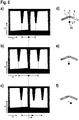
- Figure 6 shows in Fig. 6.a) to 6.c ) Image recordings of a pipette tip in different positions in the position determination space of a position detector.
- Fig. 6.d) to 6.f is a schematic cross section to illustrate the respective positions of the pipette tip in the image according to the adjacent figure on the right, ie Fig. 6.d ) shows the position to the picture in Fig. 6.a ) etc.
- a first and a second light deflecting element each a planar mirror, each illuminated by a diffuser element, can be seen in white.
- a pipette tip emerges as a black shadow image with sharp edges, which can be seen from a different perspective in each of the two halves of the image. This involves a first and a second image, which are each generated via deflected light beams.
- a third blurred image of the pipette tip is in Fig. 6.a) and 6.b ) in the area of the dark zone in the center of the image acquisition and in Fig. 6.c ) offset to the right.
- This shift is shown in a shift of the center point of the horizontal positions of the pipette tip to the right, as shown by the simple arrow at the lower edge of Fig. 6.c ) indicated.
- the blurred direct image of the pipette tip has also moved to the right.
- the z-direction is aligned parallel to the vertical direction of the image sensor and can be read directly from the V-position in the image recording.
- the z-position of the pipette tip not changed. In all image recordings it is approximately half the height with respect to vertical direction V.
- FIG. 7 A perspective view of one embodiment of a position detector 30 is shown.
- the position detector 30 in this case comprises a substantially cuboid housing 9 with an access opening 19 in an upper wall.
- a first light deflecting element 1 in the form of a planar mirror can be seen through the access opening.
- An object can be introduced into the position determination space of the position detector through the access opening 19.
- the position detector shown is suitable for measuring the position of a tip of an elongated object.
- a cable 18 leading through a wall into the housing 9 contains lines for supplying energy to the position detector and for data transmission.
- a robot system 50 with a position detector 30 is shown.
- the shown robot system is a pipetting robot system which can move a pipette in three coordinate directions x, y and z, which are represented by arrows of the coordinate system at the top left in the figure.
- the object 20, the position of which can be determined by the position detector 30, is the pipette of the pipetting robot.
- the pipetting robot includes linear axes for moving and positioning the pipette tip.
- the pipette is connected to a pump unit (not shown here) via a flexible hose Pipetting robot connected.
- the pipette tip is located directly above the access opening of the position detector and could next be lowered into the position determination space, for example, by moving the pipette in the z direction.
- Corrugated plates 51 are arranged on a work surface of the pipetting robot system within reach of the travel range of the linear axes.
- the precision with which the individual wells in the well plates 51 can be approached can be significantly increased. For reasons of clarity, only corrugated plates with 4 x 6 wells are shown here. The precision when approaching the well positions is particularly important when corrugated plates of the same size with a much larger number of wells are used on the same area, for example 8 x 12 wells, 16 x 24 wells or even 32 x 48 wells.
- FIG. 9 an embodiment of the position detector 30 is shown in perspective.
- the position detector already has that in the embodiment according to Fig. 3 discussed items.
- the housing 9 is only shown transparent for this illustration so that the arrangement of the elements within the housing can be seen.
- light sources are attached directly to the front of the camera and in Fig. 9 not directly visible.
- the light deflecting elements 1, 2 are planar mirrors here.
- the two planar mirrors each define a first and a second Plane that intersect in a straight line that is perpendicular to the optical axis of the camera.
- the two mirrors each essentially fill one half of the imaging area of the camera 3.
- An access opening 19 in the housing enables objects or at least a part of an object to be introduced into the position determination space of the position detector 30.
- the camera has a cable connection for power supply and for the transmission of image data via the cable 18.
- a base plate carries the light deflecting elements 1, 2, the diffuser elements 7, 8 and the shielding elements 17 and determines their exact position within the position detector.
- a means 31 for adjusting the alignment of the camera within the position detector is designed as a hexagon socket screw screwed into an upwardly projecting area of the base plate, which presses on a base of the camera 3 at its end. With the hexagon socket screw visible at the bottom right in the figure and a counteracting screw on the opposite side, the exact position of the camera relative to the base plate of the position detector can be set, i.e. the means 31 enables fine adjustment of the alignment of the camera with respect to the other elements of the position detector .
- Figure 10 is a cross section through the embodiment of the position detector 30 according to Fig. 9 shown.
- the cross-sectional plane is horizontal and scarce placed below the cover plate of the housing, so that the four side walls of the housing 9 are cut and a view of the elements of the position detector arranged within the housing is possible.
- the means 31, acting on a base of the camera 3 from two sides, for adjusting the alignment of the camera are clearly visible.
- Light deflecting element 1, 2, diffuser elements 7, 8 and shielding elements 17 are arranged mirror-symmetrically to a central plane (not shown) of the position detector, the central plane being perpendicular to the cross-sectional plane.
- the light deflecting elements 1 and 2 are flat mirrors here and define a space segment with an opening angle ⁇ .
- the position determination area and also the camera are located in this space segment.
- the approximate location of the position determination space 13 in the space segment with opening angle ⁇ is indicated by a circle drawn in dashed lines.
- the exact location of the position determination space 13 in this space segment is indicated by the access opening 19 (only in FIG Fig. 9 shown).
- the arrangement shown here results in a first and a second viewing area corresponding to that in FIG Fig. 2 situation shown and beam paths according to the in Fig. 3 situation shown.
- a focus distance of the lens of the camera can be adjustable.
- the camera's image sensor can, for example, have a resolution of 600 kilo-pixels or a higher resolution. Subpixel resolution can be achieved by evaluating blurring zones at the imaged edges of an object using image processing software.
- the image sensor can be designed for black and white recordings, for example.
- the image sensor can, for example, also be designed to generate red-green-blue (RGB) images.
- the position detector can, for example, be built on a base area of approximately 5 cm x 21 cm and thus have a very small space requirement within a robot system. Built in this dimension, the field-of-view (FOV) in the position determination space can be approx. 2 cm.
- FOV field-of-view
- a resolution of 10 micrometers can be achieved in the determined spatial coordinates from a camera resolution of 600 kilo-pixel.
- the position detector can have means for setting, in particular fine adjustment, of the alignment of the position detector with respect to externally predetermined coordinate axes.
- the position detector can have means for setting, in particular fine adjustment, the alignment of the camera with respect to other elements of the position detector, for example for setting the alignment with respect to a light deflecting element or with respect to a housing.
Landscapes
- General Physics & Mathematics (AREA)
- Physics & Mathematics (AREA)
- Engineering & Computer Science (AREA)
- Robotics (AREA)
- Mechanical Engineering (AREA)
- Health & Medical Sciences (AREA)
- Chemical & Material Sciences (AREA)
- Analytical Chemistry (AREA)
- Biochemistry (AREA)
- General Health & Medical Sciences (AREA)
- Immunology (AREA)
- Pathology (AREA)
- Life Sciences & Earth Sciences (AREA)
- Computer Vision & Pattern Recognition (AREA)
- Theoretical Computer Science (AREA)
- Length Measuring Devices By Optical Means (AREA)
Priority Applications (4)
| Application Number | Priority Date | Filing Date | Title |
|---|---|---|---|
| EP19177032.0A EP3745081B1 (fr) | 2019-05-28 | 2019-05-28 | Détecteur de position et procédé de détermination tridimensionnelle de position |
| JP2020084993A JP7686375B2 (ja) | 2019-05-28 | 2020-05-14 | 3d位置決定用の位置検出器及び方法 |
| US16/874,202 US11707847B2 (en) | 2019-05-28 | 2020-05-14 | Position detector and method for 3D position determination |
| CN202010462408.6A CN112013761B (zh) | 2019-05-28 | 2020-05-27 | 用于3d位置确定的位置检测器和方法 |
Applications Claiming Priority (1)
| Application Number | Priority Date | Filing Date | Title |
|---|---|---|---|
| EP19177032.0A EP3745081B1 (fr) | 2019-05-28 | 2019-05-28 | Détecteur de position et procédé de détermination tridimensionnelle de position |
Publications (2)
| Publication Number | Publication Date |
|---|---|
| EP3745081A1 true EP3745081A1 (fr) | 2020-12-02 |
| EP3745081B1 EP3745081B1 (fr) | 2023-03-22 |
Family
ID=66676245
Family Applications (1)
| Application Number | Title | Priority Date | Filing Date |
|---|---|---|---|
| EP19177032.0A Active EP3745081B1 (fr) | 2019-05-28 | 2019-05-28 | Détecteur de position et procédé de détermination tridimensionnelle de position |
Country Status (4)
| Country | Link |
|---|---|
| US (1) | US11707847B2 (fr) |
| EP (1) | EP3745081B1 (fr) |
| JP (1) | JP7686375B2 (fr) |
| CN (1) | CN112013761B (fr) |
Cited By (1)
| Publication number | Priority date | Publication date | Assignee | Title |
|---|---|---|---|---|
| CN115366090A (zh) * | 2021-05-18 | 2022-11-22 | 精工爱普生株式会社 | 机器人用手、对象物检测方法及控制装置 |
Families Citing this family (6)
| Publication number | Priority date | Publication date | Assignee | Title |
|---|---|---|---|---|
| FR3087254B1 (fr) * | 2018-10-16 | 2021-01-29 | Commissariat Energie Atomique | Configuration d'un dispositif de controle non destructif |
| CN116194252B (zh) * | 2020-07-29 | 2025-09-12 | 发那科株式会社 | 机器人系统 |
| DE102021100562B4 (de) | 2021-01-13 | 2025-03-20 | Ma Micro Automation Gmbh | Inspektionssystem und Inspektionsverfahren |
| JP7505460B2 (ja) * | 2021-07-20 | 2024-06-25 | 横河電機株式会社 | 検出装置及び検出方法 |
| EP4206679B1 (fr) * | 2021-12-29 | 2026-05-06 | TECAN Trading AG | Lecteure optique pour embout de pipette |
| DE102023131544B3 (de) * | 2023-11-13 | 2024-11-07 | droptical GmbH | Verfahren und Vorrichtung zur Erfassung mindestens eines auf einen Tragkörper aufzubringenden Objekts |
Citations (6)
| Publication number | Priority date | Publication date | Assignee | Title |
|---|---|---|---|---|
| US5486692A (en) * | 1994-10-19 | 1996-01-23 | Emhart Glass Machinery Investments Inc. | Glassware inspection machine comprising diffused light sources and two-dimensional cameras |
| US5731870A (en) * | 1995-05-24 | 1998-03-24 | Fori Automation, Inc. | Intelligent sensor method and apparatus for an optical wheel alignment machine |
| EP1489425A1 (fr) | 2003-06-20 | 2004-12-22 | Tecan Trading AG | Dispositif et méthode pour positionner les organes fonctionnels d'un bras de robot et/ou des récipients au moyen de deux barrières optiques se croisant |
| DE102006038161A1 (de) * | 2006-08-16 | 2008-02-28 | Siemens Ag | Bildgebungsvorrichtung zur Fluoreszenzbildgebung, insbesondere von Kleintieren |
| US20150330775A1 (en) * | 2012-12-12 | 2015-11-19 | The University Of Birminggham | Simultaneous multiple view surface geometry acquisition using structured light and mirrors |
| US20160291049A1 (en) * | 2013-11-04 | 2016-10-06 | Siemens Healthcare Diagnostics Inc. | Methods and apparatus for determining aspiration and/or dispensing volume and/or pipette positioning |
Family Cites Families (25)
| Publication number | Priority date | Publication date | Assignee | Title |
|---|---|---|---|---|
| US4025201A (en) * | 1975-04-21 | 1977-05-24 | Ball Brothers Service Corporation | Method and apparatus for video inspection of articles of manufacture by decussate paths of light |
| GB1600400A (en) * | 1977-10-13 | 1981-10-14 | Ti Fords Ltd | Bottle inspection apparatus |
| JPS62123378A (ja) * | 1985-11-25 | 1987-06-04 | Nissan Motor Co Ltd | 車速測定装置 |
| RU94019480A (ru) * | 1991-09-06 | 1996-06-10 | Коммонвелт Сайнтифик энд Индастриал Рисерч Организэйшн (AU) | Способ и устройство определения измерительного параметра/ов/ объекта |
| US6584805B1 (en) * | 1993-08-24 | 2003-07-01 | Coors Brewing Company | Hot bottle inspection apparatus |
| JP3303501B2 (ja) * | 1994-02-08 | 2002-07-22 | いすゞ自動車株式会社 | 液料噴霧の体積測定装置 |
| US5761540A (en) * | 1994-10-31 | 1998-06-02 | Northeast Robotics, Inc. | Illumination device with microlouver for illuminating an object with continuous diffuse light |
| DE19717488C2 (de) * | 1997-04-25 | 2003-05-15 | Baumer Optronic Gmbh | Vorrichtung zur Inspektion der Oberfläche von Objekten |
| US6455835B1 (en) * | 2001-04-04 | 2002-09-24 | International Business Machines Corporation | System, method, and program product for acquiring accurate object silhouettes for shape recovery |
| US7113624B2 (en) * | 2002-10-15 | 2006-09-26 | Palo Alto Research Center Incorporated | Imaging apparatus and method employing a large linear aperture |
| US7107125B2 (en) * | 2003-10-29 | 2006-09-12 | Applied Materials, Inc. | Method and apparatus for monitoring the position of a semiconductor processing robot |
| US7570359B2 (en) * | 2004-02-09 | 2009-08-04 | John S. Fox | Illuminating and panoramically viewing a macroscopically-sized specimen along a single viewing axis at a single time |
| JP3946716B2 (ja) * | 2004-07-28 | 2007-07-18 | ファナック株式会社 | ロボットシステムにおける3次元視覚センサの再校正方法及び装置 |
| WO2009130318A2 (fr) | 2008-04-24 | 2009-10-29 | Tecan Trading Ag | Pipetage direct dans des postes de travail de traitement de liquide commandés par ordinateur |
| US9185454B2 (en) | 2009-10-14 | 2015-11-10 | Time Warner Cable Enterprises Llc | System and method for presenting during a programming event an invitation to follow content on a social media site |
| US8898092B2 (en) | 2012-01-31 | 2014-11-25 | International Business Machines Corporation | Leveraging user-to-tool interactions to automatically analyze defects in it services delivery |
| JP6632610B2 (ja) * | 2014-05-20 | 2020-01-22 | テカン・エスピー・インコーポレイテッドTecan SP,Inc. | 微細溶出のベッドの設計によるサンプル抽出装置 |
| JP2019502905A (ja) * | 2015-11-25 | 2019-01-31 | トリナミクス ゲゼルシャフト ミット ベシュレンクテル ハフツング | 少なくとも1個の物体を光学的に検出する検出器 |
| US10234561B2 (en) * | 2016-05-09 | 2019-03-19 | Microsoft Technology Licensing, Llc | Specular reflection removal in time-of-flight camera apparatus |
| JP2019015706A (ja) * | 2017-07-11 | 2019-01-31 | ソニーセミコンダクタソリューションズ株式会社 | 撮像装置及びモニタリング装置 |
| US11668828B2 (en) * | 2017-08-28 | 2023-06-06 | Trinamix Gmbh | Detector for determining a position of at least one object |
| EP3710860A1 (fr) * | 2017-11-17 | 2020-09-23 | trinamiX GmbH | Détecteur de détermination d'une position d'au moins un objet |
| DE102018104640A1 (de) * | 2018-02-28 | 2019-08-29 | Als Automated Lab Solutions Gmbh | Kalibriervorrichtung und Verfahren zur Ermittlung der räumlichen Ausrichtung einer an einer Halterung gehaltenen Kapillare |
| DE102018114478B4 (de) * | 2018-06-15 | 2024-09-19 | Polytec Gmbh | Verfahren zur Bestimmung des Strahlverlaufs eines Messstrahls einer interferometrischen Messvorrichtung und Messvorrichtung zur interferometrischen Vermessung eines Messobjekts |
| US11506677B2 (en) * | 2018-12-21 | 2022-11-22 | Opentrons LabWorks Inc. | Systems and methods for pipette robots |
-
2019
- 2019-05-28 EP EP19177032.0A patent/EP3745081B1/fr active Active
-
2020
- 2020-05-14 JP JP2020084993A patent/JP7686375B2/ja active Active
- 2020-05-14 US US16/874,202 patent/US11707847B2/en active Active
- 2020-05-27 CN CN202010462408.6A patent/CN112013761B/zh active Active
Patent Citations (6)
| Publication number | Priority date | Publication date | Assignee | Title |
|---|---|---|---|---|
| US5486692A (en) * | 1994-10-19 | 1996-01-23 | Emhart Glass Machinery Investments Inc. | Glassware inspection machine comprising diffused light sources and two-dimensional cameras |
| US5731870A (en) * | 1995-05-24 | 1998-03-24 | Fori Automation, Inc. | Intelligent sensor method and apparatus for an optical wheel alignment machine |
| EP1489425A1 (fr) | 2003-06-20 | 2004-12-22 | Tecan Trading AG | Dispositif et méthode pour positionner les organes fonctionnels d'un bras de robot et/ou des récipients au moyen de deux barrières optiques se croisant |
| DE102006038161A1 (de) * | 2006-08-16 | 2008-02-28 | Siemens Ag | Bildgebungsvorrichtung zur Fluoreszenzbildgebung, insbesondere von Kleintieren |
| US20150330775A1 (en) * | 2012-12-12 | 2015-11-19 | The University Of Birminggham | Simultaneous multiple view surface geometry acquisition using structured light and mirrors |
| US20160291049A1 (en) * | 2013-11-04 | 2016-10-06 | Siemens Healthcare Diagnostics Inc. | Methods and apparatus for determining aspiration and/or dispensing volume and/or pipette positioning |
Cited By (1)
| Publication number | Priority date | Publication date | Assignee | Title |
|---|---|---|---|---|
| CN115366090A (zh) * | 2021-05-18 | 2022-11-22 | 精工爱普生株式会社 | 机器人用手、对象物检测方法及控制装置 |
Also Published As
| Publication number | Publication date |
|---|---|
| US20200376672A1 (en) | 2020-12-03 |
| US11707847B2 (en) | 2023-07-25 |
| CN112013761A (zh) | 2020-12-01 |
| JP7686375B2 (ja) | 2025-06-02 |
| JP2020201245A (ja) | 2020-12-17 |
| EP3745081B1 (fr) | 2023-03-22 |
| CN112013761B (zh) | 2024-09-13 |
Similar Documents
| Publication | Publication Date | Title |
|---|---|---|
| EP3745081B1 (fr) | Détecteur de position et procédé de détermination tridimensionnelle de position | |
| EP0400408B1 (fr) | Procédé pour aligner deux extrémités de fibres optiques et dispositif pour sa mise en oeuvre | |
| EP1597539B1 (fr) | Procede et systeme optique permettant de mesurer la topographie d'un objet de mesure | |
| DE60025221T2 (de) | Optisches inspektionssystem für teile im subpixel bereich | |
| DE69925582T2 (de) | Vorrichtung und verfahren zum optischen messen der oberflächenkontur eines objekts | |
| EP1618426B1 (fr) | Procede et dispositif pour determiner la position du point focal lors de l'obtention d'une image d'un echantillon | |
| DE69218627T2 (de) | Stanzpressensystem mit ccd-kamerasystem für ein automatisches dreiaxiales ausrichtungssystem für matrizen | |
| DE19721688B4 (de) | Oberflächenerfassungseinrichtung und Verfahren zur Oberflächenerfassung | |
| EP2195697B1 (fr) | Procédé pour l'analyse d'un échantillon | |
| EP0017726B1 (fr) | Procédé et dispositif de focalisation automatique d'une image | |
| EP2511648B1 (fr) | Agencement de mesure et procédé de détermination d'au moins une hauteur de sertissage d'un sertissage de conducteur | |
| DE69723213T2 (de) | System zum Messen des Spiels und der Koplanarität zweier nebeneinander liegender Objekte | |
| DE102012217240B4 (de) | Vorrichtung zum Messen einer dreidimensionalen Form | |
| DD244415A5 (de) | Verfahren zur mikrophotometrischen Untersuchung mikroskopischer Probekörper und Vorrichtung zur Durchführung des Verfahrens | |
| AT518895B1 (de) | Biegemaschine mit einer Arbeitsbereich-Bilderfassungsvorrichtung | |
| EP2887117A1 (fr) | Microscope et procédé de microscopie SPIM | |
| DE69819027T2 (de) | 3D Inspektion elektronischer Pins mit einem optischen Element, welches auf der Oberseite einer transparenten Markenplatte angeordnet ist | |
| DE2810025A1 (de) | Vorrichtung zur messung der neigung einer flaeche | |
| EP2645121A1 (fr) | Dispositif de contrôle et procédé de contrôle pour un appareil de surveillance du trafic doté d'un scanner laser | |
| DE202019105838U1 (de) | Anordnung mit einem Koordinatenmessgerät oder Mikroskop | |
| WO1992008103A1 (fr) | Procede et dispositif pour le mesurage opto-electronique d'objets | |
| DE102014219601B4 (de) | Verfahren zum Scannen einer Probe mittels einer Röntgenoptik und eine Apparatur zum Scannen einer Probe | |
| DE2259762B2 (de) | Verfahren zur automatischen Auswertung von Stereobildern | |
| DE102018008010A1 (de) | Kalibrationsverfahren einer bildmessvorrichtung und zugehöriges computerprogrammprodukt | |
| EP1178344B1 (fr) | Méthode et appareil pour la restitution d'image pour la microscopie à balayage et microscope à balayage |
Legal Events
| Date | Code | Title | Description |
|---|---|---|---|
| PUAI | Public reference made under article 153(3) epc to a published international application that has entered the european phase |
Free format text: ORIGINAL CODE: 0009012 |
|
| STAA | Information on the status of an ep patent application or granted ep patent |
Free format text: STATUS: THE APPLICATION HAS BEEN PUBLISHED |
|
| AK | Designated contracting states |
Kind code of ref document: A1 Designated state(s): AL AT BE BG CH CY CZ DE DK EE ES FI FR GB GR HR HU IE IS IT LI LT LU LV MC MK MT NL NO PL PT RO RS SE SI SK SM TR |
|
| AX | Request for extension of the european patent |
Extension state: BA ME |
|
| STAA | Information on the status of an ep patent application or granted ep patent |
Free format text: STATUS: REQUEST FOR EXAMINATION WAS MADE |
|
| 17P | Request for examination filed |
Effective date: 20210602 |
|
| RBV | Designated contracting states (corrected) |
Designated state(s): AL AT BE BG CH CY CZ DE DK EE ES FI FR GB GR HR HU IE IS IT LI LT LU LV MC MK MT NL NO PL PT RO RS SE SI SK SM TR |
|
| GRAP | Despatch of communication of intention to grant a patent |
Free format text: ORIGINAL CODE: EPIDOSNIGR1 |
|
| STAA | Information on the status of an ep patent application or granted ep patent |
Free format text: STATUS: GRANT OF PATENT IS INTENDED |
|
| INTG | Intention to grant announced |
Effective date: 20221006 |
|
| TPAC | Observations filed by third parties |
Free format text: ORIGINAL CODE: EPIDOSNTIPA |
|
| GRAS | Grant fee paid |
Free format text: ORIGINAL CODE: EPIDOSNIGR3 |
|
| GRAA | (expected) grant |
Free format text: ORIGINAL CODE: 0009210 |
|
| STAA | Information on the status of an ep patent application or granted ep patent |
Free format text: STATUS: THE PATENT HAS BEEN GRANTED |
|
| AK | Designated contracting states |
Kind code of ref document: B1 Designated state(s): AL AT BE BG CH CY CZ DE DK EE ES FI FR GB GR HR HU IE IS IT LI LT LU LV MC MK MT NL NO PL PT RO RS SE SI SK SM TR |
|
| REG | Reference to a national code |
Ref country code: GB Ref legal event code: FG4D Free format text: NOT ENGLISH |
|
| REG | Reference to a national code |
Ref country code: CH Ref legal event code: EP |
|
| REG | Reference to a national code |
Ref country code: DE Ref legal event code: R096 Ref document number: 502019007256 Country of ref document: DE |
|
| REG | Reference to a national code |
Ref country code: IE Ref legal event code: FG4D Free format text: LANGUAGE OF EP DOCUMENT: GERMAN |
|
| REG | Reference to a national code |
Ref country code: AT Ref legal event code: REF Ref document number: 1555551 Country of ref document: AT Kind code of ref document: T Effective date: 20230415 |
|
| P01 | Opt-out of the competence of the unified patent court (upc) registered |
Effective date: 20230523 |
|
| REG | Reference to a national code |
Ref country code: LT Ref legal event code: MG9D |
|
| REG | Reference to a national code |
Ref country code: NL Ref legal event code: MP Effective date: 20230322 |
|
| PG25 | Lapsed in a contracting state [announced via postgrant information from national office to epo] |
Ref country code: RS Free format text: LAPSE BECAUSE OF FAILURE TO SUBMIT A TRANSLATION OF THE DESCRIPTION OR TO PAY THE FEE WITHIN THE PRESCRIBED TIME-LIMIT Effective date: 20230322 Ref country code: NO Free format text: LAPSE BECAUSE OF FAILURE TO SUBMIT A TRANSLATION OF THE DESCRIPTION OR TO PAY THE FEE WITHIN THE PRESCRIBED TIME-LIMIT Effective date: 20230622 Ref country code: LV Free format text: LAPSE BECAUSE OF FAILURE TO SUBMIT A TRANSLATION OF THE DESCRIPTION OR TO PAY THE FEE WITHIN THE PRESCRIBED TIME-LIMIT Effective date: 20230322 Ref country code: LT Free format text: LAPSE BECAUSE OF FAILURE TO SUBMIT A TRANSLATION OF THE DESCRIPTION OR TO PAY THE FEE WITHIN THE PRESCRIBED TIME-LIMIT Effective date: 20230322 Ref country code: HR Free format text: LAPSE BECAUSE OF FAILURE TO SUBMIT A TRANSLATION OF THE DESCRIPTION OR TO PAY THE FEE WITHIN THE PRESCRIBED TIME-LIMIT Effective date: 20230322 |
|
| PG25 | Lapsed in a contracting state [announced via postgrant information from national office to epo] |
Ref country code: SE Free format text: LAPSE BECAUSE OF FAILURE TO SUBMIT A TRANSLATION OF THE DESCRIPTION OR TO PAY THE FEE WITHIN THE PRESCRIBED TIME-LIMIT Effective date: 20230322 Ref country code: NL Free format text: LAPSE BECAUSE OF FAILURE TO SUBMIT A TRANSLATION OF THE DESCRIPTION OR TO PAY THE FEE WITHIN THE PRESCRIBED TIME-LIMIT Effective date: 20230322 Ref country code: GR Free format text: LAPSE BECAUSE OF FAILURE TO SUBMIT A TRANSLATION OF THE DESCRIPTION OR TO PAY THE FEE WITHIN THE PRESCRIBED TIME-LIMIT Effective date: 20230623 Ref country code: FI Free format text: LAPSE BECAUSE OF FAILURE TO SUBMIT A TRANSLATION OF THE DESCRIPTION OR TO PAY THE FEE WITHIN THE PRESCRIBED TIME-LIMIT Effective date: 20230322 |
|
| PG25 | Lapsed in a contracting state [announced via postgrant information from national office to epo] |
Ref country code: SM Free format text: LAPSE BECAUSE OF FAILURE TO SUBMIT A TRANSLATION OF THE DESCRIPTION OR TO PAY THE FEE WITHIN THE PRESCRIBED TIME-LIMIT Effective date: 20230322 Ref country code: RO Free format text: LAPSE BECAUSE OF FAILURE TO SUBMIT A TRANSLATION OF THE DESCRIPTION OR TO PAY THE FEE WITHIN THE PRESCRIBED TIME-LIMIT Effective date: 20230322 Ref country code: PT Free format text: LAPSE BECAUSE OF FAILURE TO SUBMIT A TRANSLATION OF THE DESCRIPTION OR TO PAY THE FEE WITHIN THE PRESCRIBED TIME-LIMIT Effective date: 20230724 Ref country code: ES Free format text: LAPSE BECAUSE OF FAILURE TO SUBMIT A TRANSLATION OF THE DESCRIPTION OR TO PAY THE FEE WITHIN THE PRESCRIBED TIME-LIMIT Effective date: 20230322 Ref country code: EE Free format text: LAPSE BECAUSE OF FAILURE TO SUBMIT A TRANSLATION OF THE DESCRIPTION OR TO PAY THE FEE WITHIN THE PRESCRIBED TIME-LIMIT Effective date: 20230322 |
|
| PG25 | Lapsed in a contracting state [announced via postgrant information from national office to epo] |
Ref country code: SK Free format text: LAPSE BECAUSE OF FAILURE TO SUBMIT A TRANSLATION OF THE DESCRIPTION OR TO PAY THE FEE WITHIN THE PRESCRIBED TIME-LIMIT Effective date: 20230322 Ref country code: PL Free format text: LAPSE BECAUSE OF FAILURE TO SUBMIT A TRANSLATION OF THE DESCRIPTION OR TO PAY THE FEE WITHIN THE PRESCRIBED TIME-LIMIT Effective date: 20230322 Ref country code: IS Free format text: LAPSE BECAUSE OF FAILURE TO SUBMIT A TRANSLATION OF THE DESCRIPTION OR TO PAY THE FEE WITHIN THE PRESCRIBED TIME-LIMIT Effective date: 20230722 |
|
| REG | Reference to a national code |
Ref country code: DE Ref legal event code: R097 Ref document number: 502019007256 Country of ref document: DE |
|
| PG25 | Lapsed in a contracting state [announced via postgrant information from national office to epo] |
Ref country code: MC Free format text: LAPSE BECAUSE OF FAILURE TO SUBMIT A TRANSLATION OF THE DESCRIPTION OR TO PAY THE FEE WITHIN THE PRESCRIBED TIME-LIMIT Effective date: 20230322 |
|
| PLBE | No opposition filed within time limit |
Free format text: ORIGINAL CODE: 0009261 |
|
| STAA | Information on the status of an ep patent application or granted ep patent |
Free format text: STATUS: NO OPPOSITION FILED WITHIN TIME LIMIT |
|
| REG | Reference to a national code |
Ref country code: BE Ref legal event code: MM Effective date: 20230531 |
|
| PG25 | Lapsed in a contracting state [announced via postgrant information from national office to epo] |
Ref country code: SI Free format text: LAPSE BECAUSE OF FAILURE TO SUBMIT A TRANSLATION OF THE DESCRIPTION OR TO PAY THE FEE WITHIN THE PRESCRIBED TIME-LIMIT Effective date: 20230322 Ref country code: MC Free format text: LAPSE BECAUSE OF FAILURE TO SUBMIT A TRANSLATION OF THE DESCRIPTION OR TO PAY THE FEE WITHIN THE PRESCRIBED TIME-LIMIT Effective date: 20230322 Ref country code: LU Free format text: LAPSE BECAUSE OF NON-PAYMENT OF DUE FEES Effective date: 20230528 Ref country code: DK Free format text: LAPSE BECAUSE OF FAILURE TO SUBMIT A TRANSLATION OF THE DESCRIPTION OR TO PAY THE FEE WITHIN THE PRESCRIBED TIME-LIMIT Effective date: 20230322 Ref country code: CZ Free format text: LAPSE BECAUSE OF FAILURE TO SUBMIT A TRANSLATION OF THE DESCRIPTION OR TO PAY THE FEE WITHIN THE PRESCRIBED TIME-LIMIT Effective date: 20230322 |
|
| 26N | No opposition filed |
Effective date: 20240102 |
|
| REG | Reference to a national code |
Ref country code: IE Ref legal event code: MM4A |
|
| PG25 | Lapsed in a contracting state [announced via postgrant information from national office to epo] |
Ref country code: IE Free format text: LAPSE BECAUSE OF NON-PAYMENT OF DUE FEES Effective date: 20230528 |
|
| PG25 | Lapsed in a contracting state [announced via postgrant information from national office to epo] |
Ref country code: IE Free format text: LAPSE BECAUSE OF NON-PAYMENT OF DUE FEES Effective date: 20230528 |
|
| PG25 | Lapsed in a contracting state [announced via postgrant information from national office to epo] |
Ref country code: IT Free format text: LAPSE BECAUSE OF FAILURE TO SUBMIT A TRANSLATION OF THE DESCRIPTION OR TO PAY THE FEE WITHIN THE PRESCRIBED TIME-LIMIT Effective date: 20230322 Ref country code: BE Free format text: LAPSE BECAUSE OF NON-PAYMENT OF DUE FEES Effective date: 20230531 |
|
| PG25 | Lapsed in a contracting state [announced via postgrant information from national office to epo] |
Ref country code: BG Free format text: LAPSE BECAUSE OF FAILURE TO SUBMIT A TRANSLATION OF THE DESCRIPTION OR TO PAY THE FEE WITHIN THE PRESCRIBED TIME-LIMIT Effective date: 20230322 |
|
| PG25 | Lapsed in a contracting state [announced via postgrant information from national office to epo] |
Ref country code: BG Free format text: LAPSE BECAUSE OF FAILURE TO SUBMIT A TRANSLATION OF THE DESCRIPTION OR TO PAY THE FEE WITHIN THE PRESCRIBED TIME-LIMIT Effective date: 20230322 |
|
| PGFP | Annual fee paid to national office [announced via postgrant information from national office to epo] |
Ref country code: DE Payment date: 20250402 Year of fee payment: 7 |
|
| PGFP | Annual fee paid to national office [announced via postgrant information from national office to epo] |
Ref country code: GB Payment date: 20250401 Year of fee payment: 7 |
|
| REG | Reference to a national code |
Ref country code: AT Ref legal event code: MM01 Ref document number: 1555551 Country of ref document: AT Kind code of ref document: T Effective date: 20240528 |
|
| PGFP | Annual fee paid to national office [announced via postgrant information from national office to epo] |
Ref country code: FR Payment date: 20250401 Year of fee payment: 7 |
|
| PGFP | Annual fee paid to national office [announced via postgrant information from national office to epo] |
Ref country code: CH Payment date: 20250601 Year of fee payment: 7 |
|
| PG25 | Lapsed in a contracting state [announced via postgrant information from national office to epo] |
Ref country code: AT Free format text: LAPSE BECAUSE OF NON-PAYMENT OF DUE FEES Effective date: 20240528 |
|
| PG25 | Lapsed in a contracting state [announced via postgrant information from national office to epo] |
Ref country code: CY Free format text: LAPSE BECAUSE OF FAILURE TO SUBMIT A TRANSLATION OF THE DESCRIPTION OR TO PAY THE FEE WITHIN THE PRESCRIBED TIME-LIMIT; INVALID AB INITIO Effective date: 20190528 |
|
| PG25 | Lapsed in a contracting state [announced via postgrant information from national office to epo] |
Ref country code: HU Free format text: LAPSE BECAUSE OF FAILURE TO SUBMIT A TRANSLATION OF THE DESCRIPTION OR TO PAY THE FEE WITHIN THE PRESCRIBED TIME-LIMIT; INVALID AB INITIO Effective date: 20190528 |
|
| PG25 | Lapsed in a contracting state [announced via postgrant information from national office to epo] |
Ref country code: TR Free format text: LAPSE BECAUSE OF FAILURE TO SUBMIT A TRANSLATION OF THE DESCRIPTION OR TO PAY THE FEE WITHIN THE PRESCRIBED TIME-LIMIT Effective date: 20230322 |
|
| PGFP | Annual fee paid to national office [announced via postgrant information from national office to epo] |
Ref country code: AT Payment date: 20260410 Year of fee payment: 5 |