EP3745096B1 - Dispositif ainsi que procédé de mesure de fluide, et programme - Google Patents
Dispositif ainsi que procédé de mesure de fluide, et programme Download PDFInfo
- Publication number
- EP3745096B1 EP3745096B1 EP19744057.1A EP19744057A EP3745096B1 EP 3745096 B1 EP3745096 B1 EP 3745096B1 EP 19744057 A EP19744057 A EP 19744057A EP 3745096 B1 EP3745096 B1 EP 3745096B1
- Authority
- EP
- European Patent Office
- Prior art keywords
- fluid
- light
- optical emitter
- optical
- flow channel
- Prior art date
- Legal status (The legal status is an assumption and is not a legal conclusion. Google has not performed a legal analysis and makes no representation as to the accuracy of the status listed.)
- Active
Links
Images



Classifications
-
- G—PHYSICS
- G01—MEASURING; TESTING
- G01F—MEASURING VOLUME, VOLUME FLOW, MASS FLOW OR LIQUID LEVEL; METERING BY VOLUME
- G01F1/00—Measuring the volume flow or mass flow of fluid or fluent solid material wherein the fluid passes through a meter in a continuous flow
- G01F1/66—Measuring the volume flow or mass flow of fluid or fluent solid material wherein the fluid passes through a meter in a continuous flow by measuring frequency, phase shift or propagation time of electromagnetic or other waves, e.g. using ultrasonic flowmeters
- G01F1/663—Measuring the volume flow or mass flow of fluid or fluent solid material wherein the fluid passes through a meter in a continuous flow by measuring frequency, phase shift or propagation time of electromagnetic or other waves, e.g. using ultrasonic flowmeters by measuring Doppler frequency shift
-
- G—PHYSICS
- G01—MEASURING; TESTING
- G01F—MEASURING VOLUME, VOLUME FLOW, MASS FLOW OR LIQUID LEVEL; METERING BY VOLUME
- G01F1/00—Measuring the volume flow or mass flow of fluid or fluent solid material wherein the fluid passes through a meter in a continuous flow
- G01F1/66—Measuring the volume flow or mass flow of fluid or fluent solid material wherein the fluid passes through a meter in a continuous flow by measuring frequency, phase shift or propagation time of electromagnetic or other waves, e.g. using ultrasonic flowmeters
- G01F1/661—Measuring the volume flow or mass flow of fluid or fluent solid material wherein the fluid passes through a meter in a continuous flow by measuring frequency, phase shift or propagation time of electromagnetic or other waves, e.g. using ultrasonic flowmeters using light
-
- A—HUMAN NECESSITIES
- A61—MEDICAL OR VETERINARY SCIENCE; HYGIENE
- A61B—DIAGNOSIS; SURGERY; IDENTIFICATION
- A61B5/00—Measuring for diagnostic purposes; Identification of persons
- A61B5/02—Detecting, measuring or recording for evaluating the cardiovascular system, e.g. pulse, heart rate, blood pressure or blood flow
- A61B5/026—Measuring blood flow
- A61B5/0261—Measuring blood flow using optical means, e.g. infrared light
-
- G—PHYSICS
- G01—MEASURING; TESTING
- G01F—MEASURING VOLUME, VOLUME FLOW, MASS FLOW OR LIQUID LEVEL; METERING BY VOLUME
- G01F1/00—Measuring the volume flow or mass flow of fluid or fluent solid material wherein the fluid passes through a meter in a continuous flow
- G01F1/66—Measuring the volume flow or mass flow of fluid or fluent solid material wherein the fluid passes through a meter in a continuous flow by measuring frequency, phase shift or propagation time of electromagnetic or other waves, e.g. using ultrasonic flowmeters
- G01F1/662—Constructional details
-
- G—PHYSICS
- G01—MEASURING; TESTING
- G01P—MEASURING LINEAR OR ANGULAR SPEED, ACCELERATION, DECELERATION, OR SHOCK; INDICATING PRESENCE, ABSENCE, OR DIRECTION, OF MOVEMENT
- G01P5/00—Measuring speed of fluids, e.g. of air stream; Measuring speed of bodies relative to fluids, e.g. of ship, of aircraft
- G01P5/26—Measuring speed of fluids, e.g. of air stream; Measuring speed of bodies relative to fluids, e.g. of ship, of aircraft by measuring the direct influence of the streaming fluid on the properties of a detecting optical wave
-
- A—HUMAN NECESSITIES
- A61—MEDICAL OR VETERINARY SCIENCE; HYGIENE
- A61B—DIAGNOSIS; SURGERY; IDENTIFICATION
- A61B2562/00—Details of sensors; Constructional details of sensor housings or probes; Accessories for sensors
- A61B2562/02—Details of sensors specially adapted for in-vivo measurements
- A61B2562/0233—Special features of optical sensors or probes classified in A61B5/00
-
- A—HUMAN NECESSITIES
- A61—MEDICAL OR VETERINARY SCIENCE; HYGIENE
- A61B—DIAGNOSIS; SURGERY; IDENTIFICATION
- A61B5/00—Measuring for diagnostic purposes; Identification of persons
- A61B5/02—Detecting, measuring or recording for evaluating the cardiovascular system, e.g. pulse, heart rate, blood pressure or blood flow
- A61B5/026—Measuring blood flow
- A61B5/0285—Measuring or recording phase velocity of blood waves
Definitions
- the present disclosure relates to a fluid measurement apparatus, a fluid measurement method, and a program.
- JP 2017-113320 A discloses a fluid evaluation apparatus that obtains at least one of the flow amount and flow velocity of a fluid flowing inside a tube, a living body, or the like.
- WO 2016/092679 A1 discloses a blood flow sensor for measuring the flow speed of blood passing through a transparent tube, the sensor being provided with a light-emitting element which emits a laser beam, a reflective body which reflects the beam, and a light-receiving element which receives light.
- WO 2016/132512 A1 discloses a flow rate measurement device comprising a tube and a sensor unit which is detachably connected to the tube, wherein the tube includes a transparent tube wall and a light blocking film which covers a portion of the tube wall, and wherein a light emitting element opening and a light receiving element opening for reflected light are formed on the light blocking film.
- the present invention provides a fluid measurement apparatus according to claim 1; a fluid measurement method according to claim 10; and a non-transitory computer-readable recording medium according to claim 13. Preferred embodiments are described in the dependent claims.
- a fluid measurement apparatus can be more convenient if it is capable of estimating a flow state of a fluid under various conditions.
- the present disclosure relates to providing a highly convenient fluid measurement apparatus, fluid measurement method, and program. According to an embodiment, it is possible to provide a highly convenient fluid measurement apparatus, fluid measurement method, and program. An embodiment of the present disclosure will be described below, with reference to the drawings. First, a structure of a fluid measurement apparatus according to an embodiment will be described below.
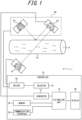
- FIG. 1 is a block diagram illustrating an example of a schematic structure of a fluid measurement apparatus according to an embodiment.
- a power source that supplies power to each functional unit, a structure of supplying power from the power source to each functional unit, and the like are not illustrated in the drawing.
- Functional units illustrated in FIG. 1 may be included in or omitted from a fluid measurement apparatus 1 according to an embodiment as appropriate.
- the fluid measurement apparatus can measure a flow state (e.g. flow velocity or flow amount) of a flowing object (fluid). Specifically, the fluid measurement apparatus can calculate the flow amount or flow velocity of the fluid as the flow state of the fluid.
- the flow amount is the volume or mass of the fluid flowing per unit time, and the flow velocity is the distance the fluid travels per unit time.
- the fluid measurement apparatus can calculate the flow state of the fluid using the Doppler effect of light.
- Light applied to an irradiated object (the fluid, a flow channel in which the fluid flows, and the like) is scattered by the fluid, and its frequency is shifted (Doppler-shifted) due to the Doppler effect depending on the flow state of the fluid.
- the Doppler effect can be used to calculate the flow state.
- the fluid measurement apparatus can emit light from an optical emitter toward the irradiated object including the fluid to be measured, and receive, by an optical detector, interference light including light scattered by the irradiated object. The fluid measurement apparatus can then calculate the flow state of the fluid based on the output of the optical detector.
- the fluid to be measured is not limited, as long as it has translucency and its flow state can be calculated using the Doppler effect of light.
- the fluid is any fluid that scatters light by itself or contains a substance (scattering substance) that scatters light.
- the fluid include liquids such as water, blood, milk, printer ink, and oil, and gases containing solids such as a powder. At least part of the fluid has translucency.
- the fluid measurement apparatus may regard the flow amount or flow velocity of the scattering substance, the powder, or the like as the flow amount or velocity of the fluid. That is, the "flow amount or flow velocity of the fluid" can be interpreted as the "flow amount or flow velocity of the scattering substance, the powder, or the like".
- the fluid measurement apparatus 1 includes an estimation unit 16 that estimates the flow state based on received light.
- the fluid measurement apparatus 1 may also include, for example, at least one of a sensor 60 and a first optical emitter 61.
- the first optical emitter 61 can emit light such as laser light toward a flow channel 70.
- the sensor 60 can perform detection relating to a fluid A flowing in the flow channel 70.
- the estimation unit 16 can estimate the flow state of the fluid A flowing in the flow channel 70, based on the result of detection by the sensor 60.
- the first optical emitter 61 is positioned with respect to the flow channel 70 so that light can be emitted toward the fluid A flowing in the flow channel 70.
- the sensor 60 is positioned with respect to the flow channel 70 so that the flow state of the fluid A flowing in the flow channel 70 can be estimated.
- the sensor 60 includes a second optical emitter 62 and an optical detector 64.
- the first optical emitter 61, the second optical emitter 62, the optical detector 64, and the flow channel 70 are positioned as appropriate so as to satisfy the following conditions:
- the first optical emitter 61 and the second optical emitter 62 may each be composed of, for example, any number of laser diodes (LDs).
- the first optical emitter 61 and the second optical emitter 62 can emit light toward the flow channel 70.
- the first optical emitter 61 and the second optical emitter 62 can emit laser light or the like.
- the first optical emitter 61 and the second optical emitter 62 may each be any optical emitter capable of emitting light of a wavelength with which the measured object contained in the fluid A is detectable.
- a driver 50 can drive the first optical emitter 61, the second optical emitter 62, and the optical detector 64.
- the driver 50 may be composed of, for example, any laser drive circuit.
- the driver 50 may be included in the fluid measurement apparatus 1, or provided outside the fluid measurement apparatus 1.
- the driver 50 may be included in the sensor 60, or provided outside the sensor 60.
- the optical detector 64 may be composed of, for example, any number of photodiodes (PDs).
- the optical detector 64 can receive at least part of at least one of light emitted from the first optical emitter 61 and light emitted from the second optical emitter 62.
- the optical detector 64 can receive light (transmitted light) transmitted through the fluid A in the flow channel 70 from among the light emitted from the first optical emitter 61 toward the flow channel 70. That is, the optical detector 64 can receive light (forward scattered light) scattered forward by the fluid A.
- the optical detector 64 can also receive light (reflected light) reflected by the flow channel 70 from among the light emitted from the second optical emitter 62 toward the flow channel 70.
- a signal relating to the intensity of light (received light) received by the optical detector 64 is transmitted to a generator 12.
- the generator 12 will be described later.
- the fluid measurement apparatus 1 may use any type of amplifier and/or filter (not illustrated) when transmitting the signal relating to the intensity of the received light to the generator 12 and processing it.
- the flow channel 70 in which the fluid A flows may be a tubular member made of any type of material.
- the flow channel 70 may be configured to prevent the fluid A from leaking so that the flow state of the fluid A can be measured appropriately.
- the flow channel 70 may be a tube made of plastic, vinyl chloride, glass, or the like.
- the flow channel 70 may be a tissue forming a flow channel through which a body fluid of a human, an animal, or the like flows, such as a blood vessel.
- the flow channel 70 may be made of a material that transmits at least part of light emitted from the first optical emitter 61 and/or light emitted from the second optical emitter 62.
- the shape of the flow channel 70 is not limited, as long as it allows the fluid A to flow.
- the shape of the flow channel 70 may be, for example, any of a circle, a rectangle, and other polygons.
- FIG. 1 schematically illustrates a state in which the fluid A flows in the flow channel 70.
- the fluid A contains particles or fine particles
- the particles or fine particles contained in the fluid A move with the flow of the fluid A.
- the first optical emitter 61 is positioned with respect to the flow channel 70 and/or the sensor 60 so that the flow state of the fluid A flowing in the flow channel 70 can be appropriately measured by the sensor 60. Specifically, the first optical emitter 61 is positioned so that light can be appropriately emitted to the fluid A flowing in the flow channel 70. The first optical emitter 61 is also positioned with respect to the flow channel 70 and/or the optical detector 64 so that light emitted from the first optical emitter 61 and transmitted through the flow channel 70 and the fluid A can be appropriately received by the optical detector 64.
- the first optical emitter 61 and the second optical emitter 62 are arranged on opposite sides of the flow channel 70, in a planar view in a direction in which the fluid A flows in the flow channel 70. That is, the first optical emitter 61 and the second optical emitter 62 are arranged on opposite sides with the flow channel 70 therebetween. This allows the optical detector 64 to receive both transmitted light and reflected light.
- the second optical emitter 62 and/or the optical detector 64 are positioned with respect to the flow channel 70 so that the flow state of the fluid A flowing in the flow channel 70 can be measured appropriately.
- the second optical emitter 62 is positioned so that light can be appropriately emitted to the flow channel 70.
- the optical detector 64 is positioned so that light emitted from the second optical emitter 62 and reflected by the flow channel 70 can be received appropriately.
- the second optical emitter 62 and the optical detector 64 may be provided separately.
- the first optical emitter 61 may be a part of a sensor of one package including the optical detector.
- the fluid measurement apparatus 1 will be described in more detail below.
- the fluid measurement apparatus 1 includes a controller 10 that controls the whole apparatus.
- the controller 10 includes the generator 12 and the estimation unit 16.
- the controller 10 may also include an adjustor 18.
- the controller 10 may also include at least one of a memory 20, a communication interface 30, a display 40, and the driver 50 as appropriate.
- the controller 10 includes at least one processor such as a central processing unit (CPU), to provide control and processing capacity for achieving various functions of the generator 12, the estimation unit 16, the adjustor 18, and the like.
- the controller 10 may implement the functions of the generator 12, the estimation unit 16, the adjustor 18, and the like by one processor, by several processors, or by respective separate processors.
- Each processor may be implemented as a single integrated circuit.
- Each processor may be implemented as a plurality of integrated circuits and/or discrete circuits communicably connected to one another.
- Each processor may be implemented based on any of various conventionally known techniques.
- the functions of the generator 12, the estimation unit 16, and the adjustor 18 may be implemented, for example, by a CPU and a program executed by the CPU.
- the generator 12 generates a frequency spectrum S according to an embodiment.
- the generation of the frequency spectrum S by the generator 12 will be described in detail later.
- the estimation unit 16 can estimate the flow state of the fluid A based on the frequency spectrum S.
- the estimation of the flow state of the fluid A by the estimation unit 16 will be described in detail later.
- the adjustor 18 can adjust the light quantity of light received by the optical detector 64, by adjusting, for example, the intensity of light emitted from the first optical emitter 61 and received by the optical detector 64 and/or the intensity of light emitted from the second optical emitter 62 and received by the optical detector 64.
- the adjustment of the light quantity by the adjustor 18 will be described in detail later.
- the "light quantity” herein refers to the quantity of light received by the optical detector 64, and indicates the amount of light energy.
- the memory 20 may include semiconductor memory, magnetic memory, etc.
- the memory 20 may store various information, programs to be executed, and the like.
- the memory 20 may function, for example, as working memory of the generator 12 and/or the estimation unit 16.
- the memory 20 may store various information used to estimate the flow state of the fluid A from the frequency spectrum S generated by the generator 12.
- the memory 20 may store the foregoing various information beforehand, or acquire the information through external communication or the like and store them.
- the memory 20 may store the foregoing various information as any of various memory cards.
- the memory 20 may be included in, for example, the generator 12 and/or the estimation unit 16.
- the communication interface 30 can achieve various functions such as wireless communication.
- the communication interface 30 may achieve communication by any of various communication systems such as Long Term Evolution (LTE).
- LTE Long Term Evolution
- the communication interface 30 may include a modem with a communication system standardized in the International Telecommunication Union Telecommunication Standardization Sector (ITU-T), for example.
- ITU-T International Telecommunication Union Telecommunication Standardization Sector
- the communication interface 30 may, for example, wirelessly communicate with an external apparatus such as an external server or a cloud server via a network, through an antenna.
- the communication interface 30 may receive the foregoing various information from an external database such as an external server or a cloud server. Such information received by the communication interface 30 may be stored in the memory 20.
- the display 40 can provide information such as the flow state of the fluid A to a user as video, by displaying the measurement result of the flow state of the fluid A or the like on a display device such as a liquid crystal display (LCD), an organic EL display, or an inorganic EL display.
- a display device such as a liquid crystal display (LCD), an organic EL display, or an inorganic EL display.
- the display 40 may display images of characters, figures, signs, graphs, and the like on the display device.
- the display 40 may display images of objects for operation and the like on the display device.
- the form of information presented by the display 40 is not limited to a form that has visual effect on the user.
- the display 40 may output information such as the flow state of the fluid A from an audio device such as a speaker as sound.
- the display 40 may provide information such as the measurement result to the user as sound and video, using the audio device and the display device.
- the display 40 may have any structure that can notify the user of the flow state of the fluid A.
- the memory 20, the communication interface 30, the display 40, and the driver 50 may each be included in the fluid measurement apparatus 1 or provided outside the fluid measurement apparatus 1.
- the display device may be included in the sensor 60 or provided outside the sensor 60.
- FIG. 2 is a diagram for explaining detection of scattered light in fluid measurement according to an embodiment.
- the first optical emitter 61, the second optical emitter 62 and the optical detector 64 in the sensor 60, and the flow channel 70 in which the fluid A flows are enlarged in the drawing.
- FIG. 2 schematically illustrates a state in which the fluid A flows in the right direction at a velocity V in the flow channel 70. In the case where the fluid A contains fine particles, the fine particles flow at the velocity V in the flow channel 70, too.
- Light emitted from the first optical emitter 61 toward the flow channel 70 includes incident light Le1.
- the incident light Le1 is light of a frequency f0 when emitted from the first optical emitter 61.
- the incident light Le1 of the frequency f0 is denoted by Le1(f0).
- Light emitted from the second optical emitter 62 toward the flow channel 70 includes incident light Le2.
- the incident light Le2 is light of the frequency f0 when emitted from the second optical emitter 62.
- the incident light Le2 of the frequency f0 is denoted by Le2(f0).
- the incident light Le2 is reflected by the flow channel 70. That is, the incident light Le2 is not scattered by the fluid A but scattered by the flow channel 70 to become scattered light Lr2.
- the scattered light Lr2 results from scattering of the incident light Le2 by the stationary flow channel 70.
- the frequency f0 of the incident light Le2 is unchanged.
- the scattered light Lr2 of the frequency f0 is denoted by Lr2(f0).
- second light Lr2 light not shifted in frequency from among light emitted from the second optical emitter 62 and received by the optical detector 64.
- At least part of the incident light Le1 is not reflected by the flow channel 70 but transmitted through the flow channel 70. That is, at least part of the incident light Le1 is not scattered by the flow channel 70 but scattered by the fluid A to become scattered light Lr1.
- the frequency of the scattered light Lr1 is Doppler-shifted depending on the moving velocity of the fluid A, and as a result slightly changes from f0.
- the scattered light Lr1 whose frequency has changed from f0 by ⁇ f is denoted by Lr1(f0 + ⁇ f).
- light shifted in frequency as a result of being transmitted through the fluid A flowing in the flow channel 70 from among light emitted from the first optical emitter 61 and received by the optical detector 64 is also referred to as "first light Lr1".
- the fluid measurement apparatus 1 can estimate the flow state of the fluid A, based on output from the optical detector 64 that has received the scattered light Lr1 and the scattered light Lr2.
- Fluid measurement by the fluid measurement apparatus 1 will be described below.
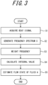
- FIG. 3 is a flowchart illustrating fluid measurement according to an embodiment.
- the generator 12 acquires a beat signal of interference light produced as a result of interference between scattered light (second light) Lr2 from the stationary flow channel 70 and scattered light (first light) Lr1 from the moving fluid A, based on output from the optical detector 64 (step S1).
- the beat signal indicates the relationship between the intensity of signal output from the optical detector 64 and time.
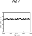
- FIG. 4 is a diagram illustrating an example of the beat signal acquired in step S1 in FIG. 3 .
- the vertical axis represents the intensity of signal output
- the horizontal axis represents time.
- the signal output from the optical detector 64 is voltage value, and is expressed in voltage unit (V) as signal output Vs.
- the beat signal is not limited to voltage, as long as it indicates temporal changes in the intensity of signal output.
- the beat signal may be current value or resistance value.
- the generator 12 After the beat signal is acquired in step S1, the generator 12 generates a frequency spectrum S from the acquired beat signal (step S2).
- the frequency spectrum S is a spectrum indicating signal intensity for each frequency component, and is generated based on the beat signal at a predetermined time.
- the generator 12 can generate the frequency spectrum S at the predetermined time by performing a fast Fourier transform (FFT) on the beat signal at the predetermined time acquired in step S1.
- FFT fast Fourier transform
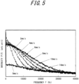
- FIG. 5 is a diagram illustrating an example of the frequency spectrum S generated in step S2 in FIG. 3 .
- the frequency spectrum S represents the relationship between the intensity of signal output of the optical detector 64 at a predetermined time and frequency.
- the vertical axis represents intensity P(f) of signal output in arbitrary units
- the horizontal axis represents frequency f.
- the frequency spectrum S is a spectrum (frequency spectrum) representing power at the predetermined time as a function of frequency based on the beat signal.
- the Doppler shift frequency depends on the velocity of the fluid A.
- FIG. 5 illustrates respective frequency spectra S generated from several beat signals acquired by changing the flow velocity of the fluid A.
- respective frequency spectra S in the cases where the flow velocity of the fluid A is 2 mm/s, 4 mm/s, 6 mm/s, 8 mm/s, 10 mm/s, and 14 mm/s are illustrated together, as an example.
- respective frequency spectra S at a predetermined time can be generated. That is, each of the plurality of frequency spectra S illustrated in FIG. 5 is an instantaneous frequency spectrum at a predetermined time.
- the frequency spectrum S depends on the flow state. Accordingly, the fluid measurement apparatus 1 can measure the flow state based on the frequency spectrum S.
- the frequency spectrum generated by performing an FFT on the beat signal as mentioned above is hereafter also referred to as "frequency spectrum P(f)".
- step S3 the estimation unit 16 performs frequency weighting on the generated frequency spectrum P(f) according to the following Formula (1) (step S3): ⁇ ⁇ P ⁇
- step S3 the estimation unit 16 integrates the Formula (1) in an adequate frequency range to calculate an integral value expressed by the following Formula (2) (step S4): ⁇ ⁇ ⁇ P ⁇ d ⁇
- the estimation unit 16 multiplies the integral value expressed by the Formula (2) by a proportionality constant K.
- the estimation unit 16 can then calculate the following value, by normalizing the resultant value by dividing it by the total power (the square of I), i.e. a DC component, of the received light signal so as not to depend on the light reception intensity of light such as laser light (Formula (3)): K ⁇ ⁇ ⁇ P ⁇ d ⁇ I 2 ⁇
- the estimation unit 16 can then estimate the flow state of the fluid A to be measured, by comparing the value of the Formula (3) calculated for the fluid to be measured and the value of the Formula (3) calculated for the fluid in a known flow state measured beforehand (step S5).
- FIG. 6 is a diagram illustrating an example of the flow amount of the fluid calculated as described above.
- the flow amount can be measured from the frequency spectrum P(f) generated from the beat signal at each given time.
- FIG. 6 is a diagram in which an example of temporal changes in the measured flow amount is plotted.
- FIG. 6 illustrates temporal changes in the flow amount of the fluid that is blood, i.e. the blood flow amount, as an example.
- the vertical axis represents the flow amount of blood (blood flow amount), and the horizontal axis represents time.
- the blood flow amount in the vertical axis is in arbitrary units.
- the fluid measurement apparatus 1 can also estimate information such as the flow velocity of the fluid A, based on information such as the cross-sectional area of the flow channel 70.
- the fluid measurement apparatus 1 can calculate the flow amount of the fluid or the like from the frequency spectrum P(f) generated from the beat signal.
- the fluid measurement apparatus 1 includes the estimation unit 16.
- the estimation unit 16 can estimate the flow state of the fluid A.
- the estimation unit 16 can estimate the flow state of the fluid A based on the first light Lr1 shifted in frequency.
- the estimation unit 16 estimates the flow state of the fluid A based on the difference between the frequency of the first light Lr1 and the frequency of the second light Lr2.
- the optical detector 64 may receive scattered light that is light emitted from the second optical emitter 62 and scattered by the flow channel 70, and the first light Lr1.
- the estimation unit 16 may then estimate the flow state of the fluid A, based on the difference between the frequency of the scattered light emitted from the second optical emitter 62 and scattered by the flow channel 70 and the frequency of the first light Lr1.
- the flow state (e.g. flow velocity or flow amount) of the fluid can be measured appropriately and accurately under various conditions.
- the fluid measurement apparatus 1 according to an embodiment even in the case where the fluid A is a colorless and transparent liquid such as water, the flow state (e.g. flow velocity or flow amount) can be measured appropriately and accurately.
- the fluid measurement apparatus 1 according to an embodiment therefore offers high convenience.
- a flowmeter that uses the principle of Doppler shift calculates the flow amount of a fluid, for example, through arithmetic operations using primary moment for a spectrum obtained as a result of FFT analysis of a Doppler phenomenon caused by an object irradiated with laser light.
- a laser Doppler flowmetry (LDF) method is conventionally known as a method of measuring blood flow using laser light.
- the fluid measurement apparatus 1 can calculate the flow amount of blood or the like by the LDF method using only one optical emitter (second optical emitter 62) and one optical detector (optical detector 64).
- a transparent liquid such as water does not cause favorable backward scattering of laser light. It is therefore conventionally difficult to favorably estimate the flow state of a fluid such as a transparent liquid in some cases. The following will examine the measurement of the flow amount of a transparent liquid such as water.
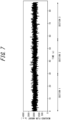
- FIG. 7 is a diagram illustrating an example of measuring the flow amount of a transparent liquid such as water based on a conventional technique.
- the measurement illustrated in FIG. 7 can be regarded as an example of calculating the flow amount of the transparent liquid using only the sensor 60 (i.e. without using the first optical emitter 61) in the fluid measurement apparatus 1 according to an embodiment. This result is equally obtained in the case of performing measurement by the conventional LDF method using the same structure.
- a transparent liquid such as water flows in a flow channel of 2 mm in diameter, as an example.
- the fluid in a flow amount known beforehand is caused to flow using, for example, a pump capable of causing the fluid to flow in a set flow amount. That is, in the example illustrated in FIG. 7 , a known flow amount is actually measured to determine measurement accuracy.
- the horizontal axis represents elapsed time (sec), and the vertical axis represents the flow amount measured (arbitrary units).
- the flow amount of the fluid is changed among sections 1, 2, and 3. Specifically, in the section 1, the fluid flows in a flow amount of 0 ml/min (i.e. the fluid is (approximately) stationary). In the section 2, the fluid flows in a flow amount of 3 ml/min. In the section 3, the fluid flows in a flow amount of 6 ml/min. However, despite the flow amount of the fluid being actually changed for each section, such change for each section is not observed in the measured flow amount, as illustrated in FIG. 7 .
- the example illustrated in FIG. 7 can be supposed as an example of measuring the fluid using only the sensor 60 (i.e. without using the first optical emitter 61) in the fluid measurement apparatus 1 illustrated in FIG. 1 , as mentioned above. At least part of light emitted from the second optical emitter in the sensor 60 is interfacially reflected by the flow channel 70 and then received by the optical detector 64. Light not interfacially reflected by the flow channel 70 from among the light emitted from the second optical emitter in the sensor 60 toward the flow channel 70 is transmitted through the fluid A. In this case, since the fluid A is transparent, the light is hardly scattered backward by the fluid A flowing in the flow channel 70.
- the optical detector 64 can hardly receive backward scattered light by the fluid A from among the light emitted from the second optical emitter. This is considered to be the reason why, despite the flow amount of the fluid being actually changed for each section, such change for each section is not observed in the measured flow amount, as can be seen in the example illustrated in FIG. 7 .
- the optical detector 64 can receive not only light emitted from the second optical emitter 62 but also light emitted from the first optical emitter 61, as illustrated in FIGS. 1 and 2 .
- the optical detector 64 can receive at least part (scattered light Lr2) of light scattered by the flow channel 70 from among light (incident light Le2) emitted from the second optical emitter 62 toward the flow channel 70.
- the optical detector 64 can also receive at least part (scattered light Lr1) of light transmitted through the fluid A flowing in the flow channel 70 from among light (incident light Le1) emitted from the first optical emitter 61 toward the flow channel 70.
- the scattered light Le1 is light (first light Lr1) shifted in frequency as a result of being transmitted through the fluid A flowing in the flow channel 70 from among light emitted from the first optical emitter 61 and received by the optical detector 64, as mentioned above.
- the scattered light Lr2 is light (second light Lr2) not shifted in frequency from among light emitted from the second optical emitter 62 and received by the optical detector 64, as mentioned above.
- the estimation unit 16 can estimate the flow state of the fluid Abased on the first light Lr1.
- the estimation unit 16 may estimate the flow state of the fluid A based on the difference between the frequency of the first light Lr1 and the frequency of the second light Lr2. Specifically, the estimation unit 16 may estimate the flow state of the fluid A based on the difference between the frequency of the scattered light scattered by the flow channel 70 from among the light emitted from the second optical emitter 62 and the frequency of the first light Lr1.
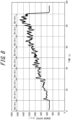
- FIG. 8 is a diagram illustrating an example of measuring a fluid that is a transparent liquid such as water in the fluid measurement apparatus 1 illustrated in FIGS. 1 and 2 .
- FIG. 8 illustrates an example of measuring a fluid that is a transparent liquid in a state in which not only the sensor 60 but also the first optical emitter 61 is appropriately operated in the fluid measurement apparatus 1 according to an embodiment.
- the horizontal axis represents elapsed time (sec)
- the vertical axis represents the flow amount measured (arbitrary units).
- the fluid in a flow amount known beforehand is caused to flow using, for example, a pump capable of causing the fluid to flow in a set flow amount. That is, in the example illustrated in FIG. 8 , too, a known flow amount is actually measured to determine measurement accuracy.
- the flow amount in the vertical axis is indicated as sensor output.
- the “sensor output” may be, for example, the intensity of light received by the optical detector 64 in the sensor 60 in the fluid measurement apparatus 1 according to an embodiment.
- the intensity of light received by the optical detector 64 for example, voltage value may be detected as signal output from the optical detector 64.
- the signal output is, however, not limited to voltage as long as it indicates temporal changes in the intensity of signal output, and may be current value, resistance value, or the like.
- sections of 10 sec are set from the measurement start, and the flow amount of the fluid is changed for each section.
- the fluid flows in a flow amount of 0 ml/min (i.e. the fluid is (approximately) stationary).
- the fluid flows in a flow amount of 1 ml/min.
- the fluid flows in a flow amount of 2 ml/min.
- the fluid flows in a flow amount of 3 ml/min. The flow amount is equally increased gradually in subsequent sections.
- the sensor output increases with the gradually increased flow amount.
- the optical detector 64 can receive light reflected by the flow channel 70, as the second light Lr2.
- the optical detector 64 can also receive light Doppler-shifted as a result of being transmitted through the fluid that is a transparent liquid such as water, as the first light Lr1.
- the fluid measurement apparatus 1 according to an embodiment can acquire a beat based on interference between the second light Lr2 and the first light Lr1.
- the fluid measurement apparatus 1 according to an embodiment can measure even a fluid that is a transparent liquid such as water.
- the flow state e.g. flow velocity or flow amount
- the fluid measurement apparatus 1 according to an embodiment therefore offers high convenience.
- the balance between the light quantity of light output from the first optical emitter 61 and the light quantity of light output from the second optical emitter 62 is important. Adjustment of the balance between the light quantity of light output from the first optical emitter 61 and the light quantity of light output from the second optical emitter 62 in the fluid measurement apparatus 1 according to an embodiment will be described below.
- the fluid measurement apparatus 1 in the case where the output based on the first light Lr1 and the output based on the second light Lr2 from among the signal output of the optical detector 64 based on the received light are not balanced, it may be difficult to favorably detect the beat formed by the first light Lr1 and the second light Lr2. If the beat formed by the first light Lr1 and the second light Lr2 cannot be favorably detected, the fluid measurement apparatus 1 according to an embodiment is likely to have difficulty in measuring the flow amount of a transparent liquid or the like with favorable accuracy.
- the balance between the output based on light emitted from the first optical emitter 61 and the output based on light emitted from the second optical emitter 62 from among the signal output of the optical detector 64 may be adjustable.
- the adjustor 18 may be capable of adjusting the light quantity of light received by the optical detector 64. This improves the usefulness of the fluid measurement apparatus 1 because the signal output of the optical detector 64 can be adjusted to enable detection of the difference between the frequency of the first light Lr1 and the frequency of the second light Lr2.
- Such light quantity adjustment in the fluid measurement apparatus 1 according to an embodiment can be performed in various ways. Some typical examples will be described below.
- the adjustor 18 may adjust the light quantity of light emitted from at least one of the first optical emitter 61 and the second optical emitter 62, through the driver 50. That is, the adjustor 18 can adjust the light quantity of received light by increasing or decreasing the light quantity of light emitted from the first optical emitter 61 and/or the second optical emitter 62.
- the adjustor 18 may adjust the power supplied from the driver 50 to the first optical emitter 61 and/or the second optical emitter 62.
- the adjustor 18 may adjust the current or voltage supplied from the driver 50 to the first optical emitter 61 and/or the second optical emitter 62.
- an electrically-operated or manually-operated slit or the like may be provided in the first optical emitter 61 and/or the second optical emitter 62, to enable adjustment of the light quantity of light emitted from the first optical emitter 61 and/or the second optical emitter 62.
- the adjustor 18 may adjust the state of the slit or the like provided in the first optical emitter 61 and/or the second optical emitter 62, for example through the driver 50.
- the adjustor 18 may adjust the light reception sensitivity of the optical detector 64.
- any filter may be provided in the first optical emitter 61 and/or the second optical emitter 62.
- a displacement mechanism that can be driven by a motor or the like may be provided in at least one of the first optical emitter 61, the second optical emitter 62, the optical detector 64, and the flow channel 70, to enable adjustment of its position. This can change the light quantity of light received by the optical detector 64.
- the fluid measurement apparatus 1 can thus adjust the light quantity of received light to enable detection of the difference between the frequency of the first light Lr1 and the frequency of the second light Lr2.
- FIG. 9 is a diagram illustrating the adjustor 18 capable of adjusting the position of at least one of the first optical emitter 61, the second optical emitter 62, the optical detector 64, and the flow channel 70 in the fluid measurement apparatus 1 according to an embodiment.
- control lines connecting the adjustor 18 to the first optical emitter 61, the sensor 60 (second optical emitter 62 and optical detector 64), and the flow channel 70 are indicated by dashed lines.
- a displacement mechanism that can be driven by a motor or the like is provided in at least one of the first optical emitter 61, the second optical emitter 62, the optical detector 64, and the flow channel 70 connected to the adjustor 18 by a control line in FIG. 9 .
- the adjustor 18 is connected to at least one of the first optical emitter 61, the second optical emitter 62, the optical detector 64, and the flow channel 70 by a control line, to drive the displacement mechanism provided in the at least one of the first optical emitter 61, the second optical emitter 62, the optical detector 64, and the flow channel 70.
- the adjustor 18 may adjust the position of at least one of the first optical emitter 61, the second optical emitter 62, the optical detector 64, and the flow channel 70 in the fluid measurement apparatus 1 according to an embodiment.
- the adjustor 18 may adjust the distance between the optical detector 64 and the first optical emitter 61 and/or the second optical emitter 62, to adjust the light quantity of light emitted from the first optical emitter 61 and/or the second optical emitter 62 and received by the optical detector 64.
- the adjustor 18 may adjust the position of at least one of the first optical emitter 61, the second optical emitter 62, and the optical detector 64 relative to the flow channel 70.
- the displacement mechanism is not limited to an electrically-operated mechanism.
- at least one of the first optical emitter 61, the second optical emitter 62, the optical detector 64, and the flow channel 70 may be provided with a displacement mechanism capable of manually changing position.
- the user can adjust the light quantity of received light by, for example, adjusting the position while checking the measurement result displayed on the display device. This improves the usefulness of the fluid measurement apparatus 1 while reducing power consumption.
- a rotation mechanism that can be driven by a motor or the like may be provided in at least one of the first optical emitter 61, the second optical emitter 62, the optical detector 64, and the flow channel 70, to enable adjustment of its orientation (angle). This can change the light quantity of received light.
- the fluid measurement apparatus 1 can thus adjust the light quantity of received light to enable detection of the difference between the frequency of the first light Lr1 and the frequency of the second light Lr2.
- the rotation mechanism is any mechanism that realizes at least part of rotation motion.
- the rotation mechanism need not necessarily realize rotation motion of one turn, and may realize, for example, rotation motion of a half turn or a 1/4 turn. Rotation is not limited to one direction. That is, the rotation mechanism may realize rotation motion of 360 degrees.
- FIG. 9 is a diagram illustrating the adjustor 18 capable of adjusting the orientation (angle) of at least one of the first optical emitter 61, the second optical emitter 62, the optical detector 64, and the flow channel 70 in the fluid measurement apparatus 1 according to an embodiment.
- control lines connecting the adjustor 18 to the first optical emitter 61, the sensor 60 (second optical emitter 62 and optical detector 64), and the flow channel 70 are indicated by dashed lines.
- a rotation mechanism that can be driven by a motor or the like is provided in at least one of the first optical emitter 61, the second optical emitter 62, the optical detector 64, and the flow channel 70 connected to the adjustor 18 by a control line in FIG. 9 .
- the adjustor 18 is connected to at least one of the first optical emitter 61, the second optical emitter 62, the optical detector 64, and the flow channel 70 by a control line, to drive the rotation mechanism provided in the at least one of the first optical emitter 61, the second optical emitter 62, the optical detector 64, and the flow channel 70.
- the adjustor 18 may adjust the orientation (angle) of at least one of the first optical emitter 61, the second optical emitter 62, the optical detector 64, and the flow channel 70 in the fluid measurement apparatus 1 according to an embodiment.
- the adjustor 18 can change the solid angle of light incident from one direction.
- the solid angle of light received by the light receiving surface of the optical detector 64 is at its maximum. In this case, the quantity of light received by the light receiving surface of the optical detector 64 is expected to be near maximum.
- the solid angle of light received by the light receiving surface of the optical detector 64 is smaller.
- the solid angle of light received by the light receiving surface of the optical detector 64 is smaller if light is incident on the light receiving surface of the optical detector 64 from an oblique direction.
- the solid angle of light received by the light receiving surface of the optical detector 64 can be decreased with an increase of the incidence angle of light on the light receiving surface of the optical detector 64. Consequently, the light quantity of received light can be decreased.
- the adjustor 18 may adjust the incidence angle (incidence angle 1) of light emitted from the first optical emitter 61 and received by the optical detector 64 with respect to the optical detector 64. Moreover, in an embodiment, the adjustor 18 may adjust the incidence angle (incidence angle 2) of light emitted from the second optical emitter 62 and received by the optical detector 64 with respect to the optical detector 64. The adjustor 18 may adjust at least one of the incidence angle 1 and the incidence angle 2.
- the rotation mechanism is not limited to an electrically-operated mechanism.
- at least one of the first optical emitter 61, the second optical emitter 62, the optical detector 64, and the flow channel 70 may be provided with a rotation mechanism capable of manually changing orientation (angle).
- the adjustor 18 may adjust the light quantity of light emitted from at least one of the first optical emitter 61 and the second optical emitter 62 and received by the optical detector 64, to enable detection of the difference between the frequency of the first light Lr1 and the frequency of the second light Lr2.
- the optical detector 64 may be unable to favorably detect the flow state of the fluid A when the fluid A flows in the flow channel 70.
- the Doppler shift when the light emitted from the first optical emitter 61 is transmitted through the fluid A is likely to be small.
- the Doppler shift cannot be detected with sufficient sensitivity, depending on the structures of the first optical emitter 61 and the optical detector 64.
- the fluid measurement apparatus 1 may have an arrangement wherein the direction in which the fluid A flows in the flow channel 70 and the direction in which the first optical emitter 61 emits light are not orthogonal to each other.
- the first optical emitter 61 may emit light having a component in a direction parallel to the flow direction of the fluid A.
- the "direction parallel to the flow direction of the fluid A" with regard to the light emitted from the first optical emitter 61 is not limited to the same direction as the direction in which the fluid A flows, and may be the opposite direction from the direction in which the fluid A flows.
- the Doppler shift when light emitted from the first optical emitter 61 is transmitted through the fluid A can be increased.
- the first optical emitter 61 and/or the flow channel 70 may be provided with an appropriate displacement mechanism and/or a rotation mechanism, as mentioned above.
- the displacement mechanism and/or the rotation mechanism may be automatically operated or manually operated.
- the signal output of the optical detector 64 may be adjusted using, for example, the displacement mechanism and/or the rotation mechanism provided in the optical detector 64 and/or the flow channel 70.
- the signal output of the optical detector 64 may be adjusted using, for example, the displacement mechanism and/or the rotation mechanism provided in the optical detector 64 and/or the flow channel 70.
- at least one of the light emission intensity, position, and orientation (angle) of the first optical emitter 61 may be adjusted depending on the changed direction of the first optical emitter 61.
- at least one of the light reception sensitivity, position, and orientation (angle) of the optical detector 64 may be adjusted depending on the changed direction of the first optical emitter 61.
- the adjustor 18 may adjust at least one of the incidence angle of light emitted from the first optical emitter 61 with respect to the flow channel 70 and the incidence angle of light emitted from the second optical emitter 62 with respect to the flow channel 70.
- the structure of the first optical emitter 61, the second optical emitter 62, and the optical detector 64 is not limited to the example illustrated in FIGS. 1 and 9 , and may be any of various structures.
- the first optical emitter 61, the second optical emitter 62, and the optical detector 64 may each be provided separately.
- the first optical emitter 61, the second optical emitter 62, and the optical detector 64 may all be included in a sensor in one package.
- a reflector may be installed in at least part of the flow channel or outside the flow channel so as to reflect transmitted light.
- Such a fluid measurement apparatus 1 can receive reflected light of transmitted light and measure the flow amount. In this case, the optical path length of received light increases, with it being possible to achieve more suitable measurement.
- the fluid measurement apparatus 1 need not necessarily include two different optical emitters, i.e. the first optical emitter 61 and the second optical emitter 62. In other words, a simpler sensor structure may be used.
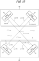
- two sensors in each of which an optical emitter and an optical detector are included in one package may be used to ease measurement by the fluid measurement apparatus 1 according to an embodiment, as illustrated in FIG. 10 .
- a first sensor 60A includes the first optical emitter 61 and a first optical detector 63
- a second sensor 60B includes the second optical emitter 62 and second optical detector 64.
- the first optical detector 63 in the first sensor 60A receives at least part of light emitted from the first optical emitter 61 and scattered by the flow channel 70.
- the first optical detector 63 also receives at least part of light emitted from the second optical emitter 62 and transmitted through the fluid A flowing in the flow channel 70.
- the fluid A is a transparent liquid such as water
- the flow state can be measured appropriately and accurately.
- a highly convenient fluid measurement apparatus can therefore be provided.
- simply by preparing two sensors each of which includes an optical emitter and an optical detector and arranging them to face each other in a staggered configuration the sensors in the fluid measurement apparatus 1 according to an embodiment can be configured easily.
- the foregoing embodiments are not limited to embodiments as the fluid measurement apparatus 1.
- the foregoing embodiments may be carried out as a fluid measurement method performed in the fluid measurement apparatus 1 or a program executed by a computer that controls an apparatus such as the fluid measurement apparatus 1.
- a fluid measurement method comprises: emitting light to an irradiated object that includes a fluid; receiving first received light transmitted through the fluid to thereby be shifted in frequency; and estimating a flow state of the fluid; receiving second received light emitted to the irradiated object and not shifted in frequency, wherein the flow state of the fluid is estimated based on a difference between a frequency of the first received light and a frequency of the second received light, wherein the irradiated object includes a flow channel in which the fluid flows, wherein the first received light is emitted by a first optical emitter, wherein the second received light is emitted by a second optical emitter, and wherein the second optical emitter is located on an opposite side of the flow channel from the first optical emitter, in a planar view in a direction in which the fluid flows in the flow channel.
- a program causes a computer to execute: emitting light from a first optical emitter to an irradiated object that includes a fluid; receiving, by an optical detector, first received light emitted from the first optical emitter and transmitted through the fluid to thereby be shifted in frequency; emitting light from a second optical emitter to the irradiated object; receiving, by the optical detector, second received light emitted from the second optical emitter and not shifted in frequency; and estimating, by an estimation unit, a flow state of the fluid based on a difference between a frequency of the first received light and a frequency of the second received light, wherein the irradiated object includes a flow channel in which the fluid flows, and wherein the second optical emitter is located on an opposite side of the flow channel from the first optical emitter, in a planar view in a direction in which the fluid flows in the flow channel.
Landscapes
- Physics & Mathematics (AREA)
- Health & Medical Sciences (AREA)
- General Physics & Mathematics (AREA)
- Electromagnetism (AREA)
- Fluid Mechanics (AREA)
- Life Sciences & Earth Sciences (AREA)
- Engineering & Computer Science (AREA)
- Surgery (AREA)
- Medical Informatics (AREA)
- Cardiology (AREA)
- Physiology (AREA)
- Veterinary Medicine (AREA)
- Biophysics (AREA)
- Pathology (AREA)
- Biomedical Technology (AREA)
- Heart & Thoracic Surgery (AREA)
- Hematology (AREA)
- Molecular Biology (AREA)
- Public Health (AREA)
- Animal Behavior & Ethology (AREA)
- General Health & Medical Sciences (AREA)
- Measuring Volume Flow (AREA)
- Multimedia (AREA)
- Aviation & Aerospace Engineering (AREA)
Claims (13)
- Appareil de mesure de fluide (1), comprenant :un premier émetteur optique (61) configuré pour émettre de la lumière vers un objet irradié qui comprend un fluide ;un détecteur optique (64) configuré pour recevoir une première lumière reçue émise par le premier émetteur optique (61) et transmise à travers le fluide et ainsi décalée en fréquence ;une unité d'estimation (16) ; etun deuxième émetteur optique (62) configuré pour émettre de la lumière vers l'objet irradié,dans lequel le détecteur optique (64) est configuré pour recevoir une deuxième lumière reçue émise par le deuxième émetteur optique (62) et non décalée en fréquence,l'unité d'estimation (16) est configurée pour estimer un état d'écoulement du fluide sur la base d'une différence entre une fréquence de la première lumière reçue et une fréquence de la deuxième lumière reçue,l'objet irradié comprend un canal d'écoulement dans lequel le fluide s'écoule, etle deuxième émetteur optique (62) est situé sur un côté du canal d'écoulement (70) opposé au premier émetteur optique (61), dans une vue en plan dans une direction dans laquelle le fluide s'écoule dans le canal d'écoulement (70).
- Appareil de mesure de fluide (1) selon la revendication 1, dans lequel la deuxième lumière reçue est de la lumière diffusée émise par le deuxième émetteur optique (62) et diffusée par le canal d'écoulement (70), et
l'unité d'estimation (16) est configurée pour estimer l'état d'écoulement du fluide sur la base d'une différence entre la fréquence de la première lumière reçue et une fréquence de la lumière diffusée. - Appareil de mesure de fluide (1) selon la revendication 1 ou 2, comprenant en outre :un ajusteur (18) configuré pour ajuster une quantité de lumière reçue par le détecteur optique (64),dans lequel l'ajusteur (18) est configuré pour ajuster au moins l'un parmi une quantité de lumière de lumière émise par le premier émetteur optique (61) et reçue par le détecteur optique (64) ; et une quantité de lumière de lumière émise par le deuxième émetteur optique (62) et reçue par le détecteur optique (64).
- Appareil de mesure de fluide (1) selon la revendication 3, dans lequel l'ajusteur (18) est configuré pour ajuster au moins l'un parmi une quantité de lumière de la lumière émise par le premier émetteur optique (61) ; et une quantité de lumière de la lumière émise par le deuxième émetteur optique (62) .
- Appareil de mesure de fluide (1) selon la revendication 3, dans lequel l'ajusteur (18) est configuré pour ajuster une position d'au moins un parmi le premier émetteur optique (61), le deuxième émetteur optique (62), le détecteur optique (64), et le canal d'écoulement (70).
- Appareil de mesure de fluide (1) selon l'une quelconque des revendications 3 à 5, dans lequel l'ajusteur (18) est configuré pour ajuster au moins l'un parmi un angle d'incidence de la lumière émise par le premier émetteur optique (61) et reçue par le détecteur optique (64), par rapport au détecteur optique (64) ; et un angle d'incidence de la lumière émise par le deuxième émetteur optique (62) et reçue par le détecteur optique (64), par rapport au détecteur optique (64).
- Appareil de mesure de fluide (1) selon l'une quelconque des revendications 3 à 6, dans lequel l'ajusteur (18) est configuré pour ajuster au moins l'un parmi : un angle d'incidence de la lumière émise par le premier émetteur optique (61), par rapport au canal d'écoulement (70) ; et un angle d'incidence de la lumière émise par le deuxième émetteur optique (62), par rapport au canal d'écoulement (70).
- Appareil de mesure de fluide (1) selon l'une quelconque des revendications 1 à 7, dans lequel le premier émetteur optique (61) est configuré pour émettre une lumière qui a une composante dans une direction parallèle à une direction d'écoulement du fluide.
- Appareil de mesure de fluide (1) selon l'une quelconque des revendications 1 à 8, dans lequel au moins une partie du fluide présente une translucidité.
- Procédé de mesure de fluide, comprenant :l'émission de lumière vers un objet irradié qui comprend un fluide ;la réception d'une première lumière reçue transmise à travers le fluide qui est ainsi décalée en fréquence ;l'estimation d'un état d'écoulement du fluide ;la réception d'une deuxième lumière reçue émise vers l'objet irradié et dont la fréquence n'est pas décalée,dans lequel l'état d'écoulement du fluide est estimé sur la base d'une différence entre une fréquence de la première lumière reçue et une fréquence de la deuxième lumière reçue,dans lequel l'objet irradié comprend un canal d'écoulement dans lequel le fluide s'écoule,dans lequel la première lumière reçue est émise par un premier émetteur optique (61),dans lequel la deuxième lumière reçue est émise par un deuxième émetteur optique (62), etdans lequel le deuxième émetteur optique (62) est situé sur un côté du canal d'écoulement (70) opposé au premier émetteur optique (61), dans une vue en plan dans une direction dans laquelle le fluide s'écoule dans le canal d'écoulement (70) .
- Procédé de mesure de fluide selon la revendication 10, dans lequella deuxième lumière reçue est une lumière diffusée qui est diffusée par le canal d'écoulement (70), etl'état d'écoulement du fluide est estimé sur la base d'une différence entre la fréquence de la première lumière reçue et une fréquence de la lumière diffusée.
- Procédé de mesure de fluide selon la revendication 10 ou 11, comprenant en outre :
l'ajustement d'au moins l'un parmi une intensité de lumière émise et une intensité de lumière reçue. - Support d'enregistrement non transitoire lisible par ordinateur qui stocke un programme de commande, le programme de commande étant configuré pour commander un appareil de mesure (1) afin d'exécuter les processus suivants :l'émission de lumière à partir d'un premier émetteur optique (61) vers un objet irradié qui comprend un fluide ;la réception, par un détecteur optique (64), d'une première lumière reçue émise par le premier émetteur optique (61) et transmise à travers le fluide, qui est ainsi décalée en fréquence ;l'émission de lumière à partir d'un deuxième émetteur optique (62) vers l'objet irradié ;la réception, par le détecteur optique (64), d'une deuxième lumière reçue émise depuis le deuxième émetteur optique (62) et non décalée en fréquence ; etl'estimation, par une unité d'estimation (16), d'un état d'écoulement du fluide sur la base d'une différence entre une fréquence de la première lumière reçue et une fréquence de la deuxième lumière reçue,dans lequel l'objet irradié comprend un canal d'écoulement dans lequel le fluide s'écoule, etdans lequel le deuxième émetteur optique (62) est situé sur un côté du canal d'écoulement (70) opposé au premier émetteur optique (61), dans une vue plane dans une direction dans laquelle le fluide s'écoule dans le canal d'écoulement (70) .
Applications Claiming Priority (2)
| Application Number | Priority Date | Filing Date | Title |
|---|---|---|---|
| JP2018011816 | 2018-01-26 | ||
| PCT/JP2019/002515 WO2019146762A1 (fr) | 2018-01-26 | 2019-01-25 | Dispositif ainsi que procédé de mesure de fluide, et programme |
Publications (3)
| Publication Number | Publication Date |
|---|---|
| EP3745096A1 EP3745096A1 (fr) | 2020-12-02 |
| EP3745096A4 EP3745096A4 (fr) | 2021-10-20 |
| EP3745096B1 true EP3745096B1 (fr) | 2024-03-20 |
Family
ID=67395986
Family Applications (1)
| Application Number | Title | Priority Date | Filing Date |
|---|---|---|---|
| EP19744057.1A Active EP3745096B1 (fr) | 2018-01-26 | 2019-01-25 | Dispositif ainsi que procédé de mesure de fluide, et programme |
Country Status (5)
| Country | Link |
|---|---|
| US (1) | US11852515B2 (fr) |
| EP (1) | EP3745096B1 (fr) |
| JP (3) | JP6746002B2 (fr) |
| CN (2) | CN111684239A (fr) |
| WO (1) | WO2019146762A1 (fr) |
Families Citing this family (7)
| Publication number | Priority date | Publication date | Assignee | Title |
|---|---|---|---|---|
| KR102955658B1 (ko) | 2019-07-03 | 2026-04-22 | 도날드슨 컴파니, 인코포레이티드 | 유체 에어레이션 검출 시스템 및 방법 |
| EP4053511A4 (fr) * | 2019-10-31 | 2023-10-18 | Kyocera Corporation | Dispositif de mesure, système de mesure, procédé de mesure et programme |
| CN111649791B (zh) * | 2020-06-18 | 2022-03-11 | 浙江省水利河口研究院 | 一种水面上测量多流态水体流量的装置及方法 |
| WO2022065429A1 (fr) * | 2020-09-28 | 2022-03-31 | 京セラ株式会社 | Dispositif, système et procédé de mesure, et programme |
| WO2022076747A1 (fr) | 2020-10-07 | 2022-04-14 | Goltzman Chad M | Système de détection d'eau dans du carburant embarqué et traitement de signaux associé |
| JP2022070650A (ja) * | 2020-10-27 | 2022-05-13 | 京セラ株式会社 | 測定装置、測定システム、測定方法及びプログラム |
| US12352697B2 (en) * | 2022-03-16 | 2025-07-08 | Donaldson Company, Inc. | Air bubble sensing systems and related signal processing |
Citations (1)
| Publication number | Priority date | Publication date | Assignee | Title |
|---|---|---|---|---|
| JPH11337475A (ja) * | 1997-11-13 | 1999-12-10 | Seitai Hikari Joho Kenkyusho:Kk | 光計測装置 |
Family Cites Families (20)
| Publication number | Priority date | Publication date | Assignee | Title |
|---|---|---|---|---|
| US3552855A (en) * | 1969-04-16 | 1971-01-05 | Us Air Force | Laser velocimeter utilizing fiber optics |
| FR2081184B1 (fr) * | 1970-03-16 | 1974-05-24 | Comp Generale Electricite | |
| CH514843A (de) * | 1970-04-27 | 1971-10-31 | Bbc Brown Boveri & Cie | Einrichtung zur Messung der lokalen Geschwindigkeiten von strömenden Medien |
| JPS5240175A (en) * | 1975-09-25 | 1977-03-28 | Nec Corp | Laser doppler current meter |
| FR2454102A1 (fr) * | 1979-02-27 | 1980-11-07 | Anvar | Procede et dispositif pour la mesure simultanee de vitesses, fluctuations de vitesses et diametres de particules submicroniques dans un fluide |
| CA2038818A1 (fr) * | 1990-03-30 | 1991-10-01 | Akio Nagamune | Methode de mesure de la distance et appareil connexe |
| FR2720839A1 (fr) * | 1994-06-07 | 1995-12-08 | Fis | Vélocimètre laser à effet doppler portable. |
| JP2006126114A (ja) * | 2004-11-01 | 2006-05-18 | Toshiba Corp | 流動状態測定システムおよび流動状態測定方法 |
| DE102009042404B3 (de) * | 2009-09-16 | 2011-04-14 | Technische Universität Dresden | Verfahren zur Bestimmung der Geschwindigkeit eines bewegten Fluids unter Einsatz einer Eigenkalibrierung eines Doppler-Global-Velozimeters mit Laserfrequenzmodulation |
| DE102010019811A1 (de) * | 2010-05-06 | 2011-11-10 | Airbus Operations Gmbh | Verfahren und Vorrichtung zur Messung der Strömungsgeschwindigkeit mittels eines Plasmas |
| US8339584B2 (en) * | 2010-05-21 | 2012-12-25 | Teledyne Technologies Incorporated | Velocity measuring system |
| EP2837327B1 (fr) * | 2012-04-13 | 2023-10-18 | Air Water Biodesign Inc. | Procédé et dispositif d'évaluation d'un fluide |
| JP6039088B2 (ja) | 2013-09-09 | 2016-12-07 | パイオニア株式会社 | 流速検出装置及び流速検出方法 |
| WO2015132880A1 (fr) * | 2014-03-04 | 2015-09-11 | パイオニア株式会社 | Dispositif de mesure et procédé de mesure |
| JP6460118B2 (ja) * | 2014-11-21 | 2019-01-30 | 富士通株式会社 | 水量計測装置及び水量モニタリングシステム |
| JPWO2016092679A1 (ja) * | 2014-12-11 | 2017-09-14 | 愛知時計電機株式会社 | 血流センサ |
| JP6404446B2 (ja) * | 2015-02-19 | 2018-10-10 | 愛知時計電機株式会社 | 流速計測装置とそれに用いる管 |
| JP6476018B2 (ja) * | 2015-03-10 | 2019-02-27 | 日本光電工業株式会社 | プローブ |
| JP6614608B2 (ja) | 2015-12-24 | 2019-12-04 | パイオニア株式会社 | 流体評価装置及び方法、コンピュータプログラム並びに記録媒体 |
| JP2018007894A (ja) * | 2016-07-14 | 2018-01-18 | 京セラ株式会社 | 測定装置、測定方法及び測定プログラム |
-
2019
- 2019-01-25 EP EP19744057.1A patent/EP3745096B1/fr active Active
- 2019-01-25 CN CN201980009764.8A patent/CN111684239A/zh active Pending
- 2019-01-25 JP JP2019538454A patent/JP6746002B2/ja active Active
- 2019-01-25 US US16/964,907 patent/US11852515B2/en active Active
- 2019-01-25 CN CN202310370126.7A patent/CN116256031A/zh active Pending
- 2019-01-25 WO PCT/JP2019/002515 patent/WO2019146762A1/fr not_active Ceased
-
2020
- 2020-08-04 JP JP2020132576A patent/JP6944027B2/ja not_active Expired - Fee Related
-
2021
- 2021-09-09 JP JP2021147022A patent/JP7291754B2/ja active Active
Patent Citations (1)
| Publication number | Priority date | Publication date | Assignee | Title |
|---|---|---|---|---|
| JPH11337475A (ja) * | 1997-11-13 | 1999-12-10 | Seitai Hikari Joho Kenkyusho:Kk | 光計測装置 |
Also Published As
| Publication number | Publication date |
|---|---|
| US20210033438A1 (en) | 2021-02-04 |
| US11852515B2 (en) | 2023-12-26 |
| JP7291754B2 (ja) | 2023-06-15 |
| EP3745096A1 (fr) | 2020-12-02 |
| JPWO2019146762A1 (ja) | 2020-02-06 |
| CN111684239A (zh) | 2020-09-18 |
| JP6746002B2 (ja) | 2020-08-26 |
| WO2019146762A1 (fr) | 2019-08-01 |
| EP3745096A4 (fr) | 2021-10-20 |
| JP2020187136A (ja) | 2020-11-19 |
| CN116256031A (zh) | 2023-06-13 |
| JP6944027B2 (ja) | 2021-10-06 |
| JP2021192053A (ja) | 2021-12-16 |
Similar Documents
| Publication | Publication Date | Title |
|---|---|---|
| US11852515B2 (en) | Fluid measurement apparatus, fluid measurement method, and program | |
| US7960707B2 (en) | Time-domain method and apparatus for determining the depth and concentration of a fluorophore in a turbid medium | |
| US9702972B2 (en) | Angle independent velocity spectrum determination | |
| US20220008637A1 (en) | Systems and methods for inline fluid characterization | |
| JP2012521003A (ja) | 流体の流れ特性を決定するための装置 | |
| US11226219B2 (en) | Fluid measurement apparatus, fluid measurement method, and program | |
| US20180249911A1 (en) | Diffusing wave spectroscopy apparatus and control method therefor | |
| US12000968B2 (en) | 2D ultrasound imaging with pulsed wave Doppler or color flow imaging | |
| JP2015089383A (ja) | 超音波プローブおよび超音波計測装置 | |
| US20160015366A1 (en) | Ultrasound vector flow imaging (vfi) with curve tracing | |
| US20190053779A1 (en) | Non-invasive blood pressure measurement devices, systems and methods | |
| EP4253935B1 (fr) | Turbidimètre | |
| JP7011097B2 (ja) | 流体測定装置、流体測定方法、及びプログラム | |
| US20180207634A1 (en) | Method for characterizing a liquid transport of a transparent liquid, corresponding liquid transport characterization apparatus and corresponding substrate material | |
| JP2014139576A (ja) | 対象物検出方法及びライダー装置、環境測定方法 | |
| JP6986265B2 (ja) | 測定システム | |
| JP2023522419A5 (fr) | ||
| RU2494422C2 (ru) | Лазерный дистанционный способ оценки мгновенной скорости и направления ветра | |
| JP6829835B2 (ja) | 生体情報測定装置 | |
| JP2020051927A (ja) | 測定システム | |
| JPH05184569A (ja) | 超音波透過検査装置 |
Legal Events
| Date | Code | Title | Description |
|---|---|---|---|
| STAA | Information on the status of an ep patent application or granted ep patent |
Free format text: STATUS: THE INTERNATIONAL PUBLICATION HAS BEEN MADE |
|
| PUAI | Public reference made under article 153(3) epc to a published international application that has entered the european phase |
Free format text: ORIGINAL CODE: 0009012 |
|
| STAA | Information on the status of an ep patent application or granted ep patent |
Free format text: STATUS: REQUEST FOR EXAMINATION WAS MADE |
|
| 17P | Request for examination filed |
Effective date: 20200724 |
|
| AK | Designated contracting states |
Kind code of ref document: A1 Designated state(s): AL AT BE BG CH CY CZ DE DK EE ES FI FR GB GR HR HU IE IS IT LI LT LU LV MC MK MT NL NO PL PT RO RS SE SI SK SM TR |
|
| AX | Request for extension of the european patent |
Extension state: BA ME |
|
| DAV | Request for validation of the european patent (deleted) | ||
| DAX | Request for extension of the european patent (deleted) | ||
| A4 | Supplementary search report drawn up and despatched |
Effective date: 20210921 |
|
| RIC1 | Information provided on ipc code assigned before grant |
Ipc: A61B 5/0285 20060101ALI20210915BHEP Ipc: A61B 5/026 20060101ALI20210915BHEP Ipc: G01F 1/66 20060101AFI20210915BHEP |
|
| P01 | Opt-out of the competence of the unified patent court (upc) registered |
Effective date: 20230508 |
|
| REG | Reference to a national code |
Free format text: PREVIOUS MAIN CLASS: G01F0001660000 Ipc: G01F0001661000 Ref country code: DE Ref legal event code: R079 Ref document number: 602019048611 Country of ref document: DE Free format text: PREVIOUS MAIN CLASS: G01F0001660000 Ipc: G01F0001661000 |
|
| GRAP | Despatch of communication of intention to grant a patent |
Free format text: ORIGINAL CODE: EPIDOSNIGR1 |
|
| STAA | Information on the status of an ep patent application or granted ep patent |
Free format text: STATUS: GRANT OF PATENT IS INTENDED |
|
| INTG | Intention to grant announced |
Effective date: 20231013 |
|
| RIC1 | Information provided on ipc code assigned before grant |
Ipc: A61B 5/026 20060101ALI20230929BHEP Ipc: G01F 1/663 20220101ALI20230929BHEP Ipc: G01F 1/661 20220101AFI20230929BHEP |
|
| GRAS | Grant fee paid |
Free format text: ORIGINAL CODE: EPIDOSNIGR3 |
|
| GRAA | (expected) grant |
Free format text: ORIGINAL CODE: 0009210 |
|
| STAA | Information on the status of an ep patent application or granted ep patent |
Free format text: STATUS: THE PATENT HAS BEEN GRANTED |
|
| AK | Designated contracting states |
Kind code of ref document: B1 Designated state(s): AL AT BE BG CH CY CZ DE DK EE ES FI FR GB GR HR HU IE IS IT LI LT LU LV MC MK MT NL NO PL PT RO RS SE SI SK SM TR |
|
| REG | Reference to a national code |
Ref country code: GB Ref legal event code: FG4D |
|
| REG | Reference to a national code |
Ref country code: CH Ref legal event code: EP |
|
| REG | Reference to a national code |
Ref country code: DE Ref legal event code: R096 Ref document number: 602019048611 Country of ref document: DE |
|
| REG | Reference to a national code |
Ref country code: IE Ref legal event code: FG4D |
|
| PG25 | Lapsed in a contracting state [announced via postgrant information from national office to epo] |
Ref country code: LT Free format text: LAPSE BECAUSE OF FAILURE TO SUBMIT A TRANSLATION OF THE DESCRIPTION OR TO PAY THE FEE WITHIN THE PRESCRIBED TIME-LIMIT Effective date: 20240320 |
|
| REG | Reference to a national code |
Ref country code: LT Ref legal event code: MG9D |
|
| PG25 | Lapsed in a contracting state [announced via postgrant information from national office to epo] |
Ref country code: GR Free format text: LAPSE BECAUSE OF FAILURE TO SUBMIT A TRANSLATION OF THE DESCRIPTION OR TO PAY THE FEE WITHIN THE PRESCRIBED TIME-LIMIT Effective date: 20240621 |
|
| PG25 | Lapsed in a contracting state [announced via postgrant information from national office to epo] |
Ref country code: RS Free format text: LAPSE BECAUSE OF FAILURE TO SUBMIT A TRANSLATION OF THE DESCRIPTION OR TO PAY THE FEE WITHIN THE PRESCRIBED TIME-LIMIT Effective date: 20240620 Ref country code: HR Free format text: LAPSE BECAUSE OF FAILURE TO SUBMIT A TRANSLATION OF THE DESCRIPTION OR TO PAY THE FEE WITHIN THE PRESCRIBED TIME-LIMIT Effective date: 20240320 |
|
| REG | Reference to a national code |
Ref country code: NL Ref legal event code: MP Effective date: 20240320 |
|
| PG25 | Lapsed in a contracting state [announced via postgrant information from national office to epo] |
Ref country code: RS Free format text: LAPSE BECAUSE OF FAILURE TO SUBMIT A TRANSLATION OF THE DESCRIPTION OR TO PAY THE FEE WITHIN THE PRESCRIBED TIME-LIMIT Effective date: 20240620 Ref country code: NO Free format text: LAPSE BECAUSE OF FAILURE TO SUBMIT A TRANSLATION OF THE DESCRIPTION OR TO PAY THE FEE WITHIN THE PRESCRIBED TIME-LIMIT Effective date: 20240620 Ref country code: LT Free format text: LAPSE BECAUSE OF FAILURE TO SUBMIT A TRANSLATION OF THE DESCRIPTION OR TO PAY THE FEE WITHIN THE PRESCRIBED TIME-LIMIT Effective date: 20240320 Ref country code: HR Free format text: LAPSE BECAUSE OF FAILURE TO SUBMIT A TRANSLATION OF THE DESCRIPTION OR TO PAY THE FEE WITHIN THE PRESCRIBED TIME-LIMIT Effective date: 20240320 Ref country code: GR Free format text: LAPSE BECAUSE OF FAILURE TO SUBMIT A TRANSLATION OF THE DESCRIPTION OR TO PAY THE FEE WITHIN THE PRESCRIBED TIME-LIMIT Effective date: 20240621 Ref country code: FI Free format text: LAPSE BECAUSE OF FAILURE TO SUBMIT A TRANSLATION OF THE DESCRIPTION OR TO PAY THE FEE WITHIN THE PRESCRIBED TIME-LIMIT Effective date: 20240320 Ref country code: BG Free format text: LAPSE BECAUSE OF FAILURE TO SUBMIT A TRANSLATION OF THE DESCRIPTION OR TO PAY THE FEE WITHIN THE PRESCRIBED TIME-LIMIT Effective date: 20240320 |
|
| REG | Reference to a national code |
Ref country code: AT Ref legal event code: MK05 Ref document number: 1668192 Country of ref document: AT Kind code of ref document: T Effective date: 20240320 |
|
| PG25 | Lapsed in a contracting state [announced via postgrant information from national office to epo] |
Ref country code: SE Free format text: LAPSE BECAUSE OF FAILURE TO SUBMIT A TRANSLATION OF THE DESCRIPTION OR TO PAY THE FEE WITHIN THE PRESCRIBED TIME-LIMIT Effective date: 20240320 Ref country code: LV Free format text: LAPSE BECAUSE OF FAILURE TO SUBMIT A TRANSLATION OF THE DESCRIPTION OR TO PAY THE FEE WITHIN THE PRESCRIBED TIME-LIMIT Effective date: 20240320 |
|
| PG25 | Lapsed in a contracting state [announced via postgrant information from national office to epo] |
Ref country code: NL Free format text: LAPSE BECAUSE OF FAILURE TO SUBMIT A TRANSLATION OF THE DESCRIPTION OR TO PAY THE FEE WITHIN THE PRESCRIBED TIME-LIMIT Effective date: 20240320 |
|
| PG25 | Lapsed in a contracting state [announced via postgrant information from national office to epo] |
Ref country code: NL Free format text: LAPSE BECAUSE OF FAILURE TO SUBMIT A TRANSLATION OF THE DESCRIPTION OR TO PAY THE FEE WITHIN THE PRESCRIBED TIME-LIMIT Effective date: 20240320 |
|
| PG25 | Lapsed in a contracting state [announced via postgrant information from national office to epo] |
Ref country code: IS Free format text: LAPSE BECAUSE OF FAILURE TO SUBMIT A TRANSLATION OF THE DESCRIPTION OR TO PAY THE FEE WITHIN THE PRESCRIBED TIME-LIMIT Effective date: 20240720 |
|
| PG25 | Lapsed in a contracting state [announced via postgrant information from national office to epo] |
Ref country code: SM Free format text: LAPSE BECAUSE OF FAILURE TO SUBMIT A TRANSLATION OF THE DESCRIPTION OR TO PAY THE FEE WITHIN THE PRESCRIBED TIME-LIMIT Effective date: 20240320 Ref country code: PT Free format text: LAPSE BECAUSE OF FAILURE TO SUBMIT A TRANSLATION OF THE DESCRIPTION OR TO PAY THE FEE WITHIN THE PRESCRIBED TIME-LIMIT Effective date: 20240722 |
|
| PG25 | Lapsed in a contracting state [announced via postgrant information from national office to epo] |
Ref country code: ES Free format text: LAPSE BECAUSE OF FAILURE TO SUBMIT A TRANSLATION OF THE DESCRIPTION OR TO PAY THE FEE WITHIN THE PRESCRIBED TIME-LIMIT Effective date: 20240320 |
|
| PG25 | Lapsed in a contracting state [announced via postgrant information from national office to epo] |
Ref country code: CZ Free format text: LAPSE BECAUSE OF FAILURE TO SUBMIT A TRANSLATION OF THE DESCRIPTION OR TO PAY THE FEE WITHIN THE PRESCRIBED TIME-LIMIT Effective date: 20240320 Ref country code: EE Free format text: LAPSE BECAUSE OF FAILURE TO SUBMIT A TRANSLATION OF THE DESCRIPTION OR TO PAY THE FEE WITHIN THE PRESCRIBED TIME-LIMIT Effective date: 20240320 |
|
| PG25 | Lapsed in a contracting state [announced via postgrant information from national office to epo] |
Ref country code: AT Free format text: LAPSE BECAUSE OF FAILURE TO SUBMIT A TRANSLATION OF THE DESCRIPTION OR TO PAY THE FEE WITHIN THE PRESCRIBED TIME-LIMIT Effective date: 20240320 |
|
| PG25 | Lapsed in a contracting state [announced via postgrant information from national office to epo] |
Ref country code: PL Free format text: LAPSE BECAUSE OF FAILURE TO SUBMIT A TRANSLATION OF THE DESCRIPTION OR TO PAY THE FEE WITHIN THE PRESCRIBED TIME-LIMIT Effective date: 20240320 |
|
| PG25 | Lapsed in a contracting state [announced via postgrant information from national office to epo] |
Ref country code: SK Free format text: LAPSE BECAUSE OF FAILURE TO SUBMIT A TRANSLATION OF THE DESCRIPTION OR TO PAY THE FEE WITHIN THE PRESCRIBED TIME-LIMIT Effective date: 20240320 |
|
| PG25 | Lapsed in a contracting state [announced via postgrant information from national office to epo] |
Ref country code: SM Free format text: LAPSE BECAUSE OF FAILURE TO SUBMIT A TRANSLATION OF THE DESCRIPTION OR TO PAY THE FEE WITHIN THE PRESCRIBED TIME-LIMIT Effective date: 20240320 Ref country code: SK Free format text: LAPSE BECAUSE OF FAILURE TO SUBMIT A TRANSLATION OF THE DESCRIPTION OR TO PAY THE FEE WITHIN THE PRESCRIBED TIME-LIMIT Effective date: 20240320 Ref country code: RO Free format text: LAPSE BECAUSE OF FAILURE TO SUBMIT A TRANSLATION OF THE DESCRIPTION OR TO PAY THE FEE WITHIN THE PRESCRIBED TIME-LIMIT Effective date: 20240320 Ref country code: PT Free format text: LAPSE BECAUSE OF FAILURE TO SUBMIT A TRANSLATION OF THE DESCRIPTION OR TO PAY THE FEE WITHIN THE PRESCRIBED TIME-LIMIT Effective date: 20240722 Ref country code: PL Free format text: LAPSE BECAUSE OF FAILURE TO SUBMIT A TRANSLATION OF THE DESCRIPTION OR TO PAY THE FEE WITHIN THE PRESCRIBED TIME-LIMIT Effective date: 20240320 Ref country code: IS Free format text: LAPSE BECAUSE OF FAILURE TO SUBMIT A TRANSLATION OF THE DESCRIPTION OR TO PAY THE FEE WITHIN THE PRESCRIBED TIME-LIMIT Effective date: 20240720 Ref country code: ES Free format text: LAPSE BECAUSE OF FAILURE TO SUBMIT A TRANSLATION OF THE DESCRIPTION OR TO PAY THE FEE WITHIN THE PRESCRIBED TIME-LIMIT Effective date: 20240320 Ref country code: EE Free format text: LAPSE BECAUSE OF FAILURE TO SUBMIT A TRANSLATION OF THE DESCRIPTION OR TO PAY THE FEE WITHIN THE PRESCRIBED TIME-LIMIT Effective date: 20240320 Ref country code: CZ Free format text: LAPSE BECAUSE OF FAILURE TO SUBMIT A TRANSLATION OF THE DESCRIPTION OR TO PAY THE FEE WITHIN THE PRESCRIBED TIME-LIMIT Effective date: 20240320 Ref country code: AT Free format text: LAPSE BECAUSE OF FAILURE TO SUBMIT A TRANSLATION OF THE DESCRIPTION OR TO PAY THE FEE WITHIN THE PRESCRIBED TIME-LIMIT Effective date: 20240320 |
|
| PG25 | Lapsed in a contracting state [announced via postgrant information from national office to epo] |
Ref country code: IT Free format text: LAPSE BECAUSE OF FAILURE TO SUBMIT A TRANSLATION OF THE DESCRIPTION OR TO PAY THE FEE WITHIN THE PRESCRIBED TIME-LIMIT Effective date: 20240320 |
|
| REG | Reference to a national code |
Ref country code: DE Ref legal event code: R097 Ref document number: 602019048611 Country of ref document: DE |
|
| PG25 | Lapsed in a contracting state [announced via postgrant information from national office to epo] |
Ref country code: IT Free format text: LAPSE BECAUSE OF FAILURE TO SUBMIT A TRANSLATION OF THE DESCRIPTION OR TO PAY THE FEE WITHIN THE PRESCRIBED TIME-LIMIT Effective date: 20240320 |
|
| PG25 | Lapsed in a contracting state [announced via postgrant information from national office to epo] |
Ref country code: DK Free format text: LAPSE BECAUSE OF FAILURE TO SUBMIT A TRANSLATION OF THE DESCRIPTION OR TO PAY THE FEE WITHIN THE PRESCRIBED TIME-LIMIT Effective date: 20240320 |
|
| PLBE | No opposition filed within time limit |
Free format text: ORIGINAL CODE: 0009261 |
|
| STAA | Information on the status of an ep patent application or granted ep patent |
Free format text: STATUS: NO OPPOSITION FILED WITHIN TIME LIMIT |
|
| PG25 | Lapsed in a contracting state [announced via postgrant information from national office to epo] |
Ref country code: DK Free format text: LAPSE BECAUSE OF FAILURE TO SUBMIT A TRANSLATION OF THE DESCRIPTION OR TO PAY THE FEE WITHIN THE PRESCRIBED TIME-LIMIT Effective date: 20240320 |
|
| 26N | No opposition filed |
Effective date: 20241223 |
|
| PG25 | Lapsed in a contracting state [announced via postgrant information from national office to epo] |
Ref country code: SI Free format text: LAPSE BECAUSE OF FAILURE TO SUBMIT A TRANSLATION OF THE DESCRIPTION OR TO PAY THE FEE WITHIN THE PRESCRIBED TIME-LIMIT Effective date: 20240320 |
|
| REG | Reference to a national code |
Ref country code: DE Ref legal event code: R119 Ref document number: 602019048611 Country of ref document: DE |
|
| REG | Reference to a national code |
Ref country code: CH Ref legal event code: PL |
|
| PG25 | Lapsed in a contracting state [announced via postgrant information from national office to epo] |
Ref country code: LU Free format text: LAPSE BECAUSE OF NON-PAYMENT OF DUE FEES Effective date: 20250125 Ref country code: MC Free format text: LAPSE BECAUSE OF FAILURE TO SUBMIT A TRANSLATION OF THE DESCRIPTION OR TO PAY THE FEE WITHIN THE PRESCRIBED TIME-LIMIT Effective date: 20240320 |
|
| GBPC | Gb: european patent ceased through non-payment of renewal fee |
Effective date: 20250125 |
|
| PG25 | Lapsed in a contracting state [announced via postgrant information from national office to epo] |
Ref country code: DE Free format text: LAPSE BECAUSE OF NON-PAYMENT OF DUE FEES Effective date: 20250801 |
|
| PG25 | Lapsed in a contracting state [announced via postgrant information from national office to epo] |
Ref country code: GB Free format text: LAPSE BECAUSE OF NON-PAYMENT OF DUE FEES Effective date: 20250125 Ref country code: BE Free format text: LAPSE BECAUSE OF NON-PAYMENT OF DUE FEES Effective date: 20250131 |
|
| PG25 | Lapsed in a contracting state [announced via postgrant information from national office to epo] |
Ref country code: FR Free format text: LAPSE BECAUSE OF NON-PAYMENT OF DUE FEES Effective date: 20250131 |
|
| PG25 | Lapsed in a contracting state [announced via postgrant information from national office to epo] |
Ref country code: CH Free format text: LAPSE BECAUSE OF NON-PAYMENT OF DUE FEES Effective date: 20250131 |
|
| REG | Reference to a national code |
Ref country code: BE Ref legal event code: MM Effective date: 20250131 |
|
| PG25 | Lapsed in a contracting state [announced via postgrant information from national office to epo] |
Ref country code: IE Free format text: LAPSE BECAUSE OF NON-PAYMENT OF DUE FEES Effective date: 20250125 |