EP3745111B1 - Dispositif et module d'essai permettant de mettre en oeuvre des essais mécaniques d'écoulement - Google Patents
Dispositif et module d'essai permettant de mettre en oeuvre des essais mécaniques d'écoulement Download PDFInfo
- Publication number
- EP3745111B1 EP3745111B1 EP19176748.2A EP19176748A EP3745111B1 EP 3745111 B1 EP3745111 B1 EP 3745111B1 EP 19176748 A EP19176748 A EP 19176748A EP 3745111 B1 EP3745111 B1 EP 3745111B1
- Authority
- EP
- European Patent Office
- Prior art keywords
- connection
- pipe
- test
- base plate
- pressure
- Prior art date
- Legal status (The legal status is an assumption and is not a legal conclusion. Google has not performed a legal analysis and makes no representation as to the accuracy of the status listed.)
- Active
Links
Images








Classifications
-
- G—PHYSICS
- G01—MEASURING; TESTING
- G01M—TESTING STATIC OR DYNAMIC BALANCE OF MACHINES OR STRUCTURES; TESTING OF STRUCTURES OR APPARATUS, NOT OTHERWISE PROVIDED FOR
- G01M10/00—Hydrodynamic testing; Arrangements in or on ship-testing tanks or water tunnels
-
- G—PHYSICS
- G09—EDUCATION; CRYPTOGRAPHY; DISPLAY; ADVERTISING; SEALS
- G09B—EDUCATIONAL OR DEMONSTRATION APPLIANCES; APPLIANCES FOR TEACHING, OR COMMUNICATING WITH, THE BLIND, DEAF OR MUTE; MODELS; PLANETARIA; GLOBES; MAPS; DIAGRAMS
- G09B23/00—Models for scientific, medical, or mathematical purposes, e.g. full-sized devices for demonstration purposes
- G09B23/06—Models for scientific, medical, or mathematical purposes, e.g. full-sized devices for demonstration purposes for physics
- G09B23/08—Models for scientific, medical, or mathematical purposes, e.g. full-sized devices for demonstration purposes for physics for statics or dynamics
- G09B23/12—Models for scientific, medical, or mathematical purposes, e.g. full-sized devices for demonstration purposes for physics for statics or dynamics of liquids or gases
Definitions
- the invention relates to a device and at least one test module for carrying out fluid mechanics tests.
- the device and the experimental module are used for technical training in the field of fluid mechanics, particularly at universities, technical colleges and technical schools.
- the HM 150 series of GUNT Actbau GmbH ( GUNT Adjust GmbH: "Equipment for engineering education. Fluid mechanics", December 31, 2018 (2018-12-31 ), Found online: URL: https://www.systemes-didactiques.fr/doc/catalogues/GU4-GUNT-GB.pdf) comprises a basic module for fluid mechanics experiments, which has an upper work surface on a mobile, supporting frame on which various experimental devices can be positioned. At the bottom of the frame is a large storage tank for test fluid with a capacity of approximately 180 l, which contains a submersible pump. The submersible pump is connected via a ball valve to an inlet in the bottom of a test flume in the work surface. The test flume can be used to conduct experiments at the weir.
- Adjacent to the test flume is a measuring tank that collects the test fluid.
- the test fluid returns to the storage tank from a drain in the bottom of the measuring tank.
- a hose for connecting the submersible pump to a test device placed on the work surface can be connected to the inlet of the test flume.
- the test fluid flows into the measuring container from an overflow or other outlet of the test device.
- the flow rate is adjusted using the ball valve.
- a level indicator is connected to the measuring container, and its outlet can be closed using a slide valve.
- the level is measured within a time period determined by a stopwatch, and the flow rate is determined from this.
- Some experimental devices are equipped with analog pressure gauges, which must be read during the tests. The results must be recorded on paper. Details on the operation of the device series and the test procedure can be found in the written instructions for use.
- test procedure especially the flow measurement, is time-consuming and inaccurate.
- the pump always runs at full power, resulting in high energy consumption, and throttling the flow rate using the ball valve causes the test fluid to heat up accordingly.
- This change in the test conditions complicates the test procedure and affects the measurement results.
- the test fluid can easily become contaminated in the open system.
- the base module and the test equipment require a lot of space.
- the HM 150.21 experimental module for visualizing flow lines in an open channel has an open frame at the bottom for mounting on the tray insert of the HM 150 experimental device. Water flows from an open experimental channel over a weir and falls through an area not covered by the open frame of the experimental module into an opening in the measuring container of the HM 150 experimental device.
- the DE 20 2015 106 972 U1 describes a test device for investigating flow fields, which has a vertical flow channel with a transparent front panel on a mobile frame, which is integrated into a circulation line in which a pump for pumping test fluid is arranged in the circuit. At least one test body is located in the flow channel. By means of a A linear electrode below the test specimen and another electrode in the flow channel with a connected electrical power supply electrolytically generate gas bubbles in the test fluid that follow the flow of the test fluid.
- the experimental device requires a large amount of space and is specialized for the investigation of flow fields.
- the US 5,324,956 describes a system for characterizing the pressure, temperature, motion, and flow patterns of a fluid under high pressure within a test cell.
- the test cell is internally lined with adjustable rock surfaces.
- the pressure is measured within the test cell using a device that employs compression-deformable optical fibers.
- Fluid velocity, flow direction, and filter cake structure are measured using laser Doppler velocimetry.
- the fluid temperature is estimated using a combination of thermal sensors.
- the invention is based on the object of providing a device and at least one test module for carrying out fluid mechanics tests, which enable a faster and more accurate execution of a large number of different fluid mechanics tests.
- test module according to claim 21.
- Advantageous embodiments of the test module are specified in subclaims.
- the test module according to the invention for carrying out fluid mechanics tests comprises a base plate for placing on a support surface and covering a first opening formed therein to a storage container of a test device, a test arrangement for fluid mechanics tests arranged on the base plate, a second connection for feeding test liquid into the test arrangement by means of a first hose and a first outlet for test liquid on the underside of the base plate, which is connected to the test arrangement via a device for conducting test liquid and/or a second outlet for test liquid above the base plate for connection to a drain line.
- the first opening of the trough-shaped reservoir is accessible directly from above through the support surface.
- the test module according to the invention (also called “module") is placed on the support surface with its base plate so that it covers the first opening of the reservoir and discharges the test fluid directly into the reservoir through the first outlet on the underside of the base plate.
- the base plate prevents splashing of test fluid and the penetration of contaminants into the test fluid.
- the test fluid is pumped through the test setup by the pump located in the table housing of the device.
- the first connection of the device can be connected to the second connection of the test module via a hose.
- the speed of the first pump can be adjusted via an electrical control device and an electric motor of the device, without heating the test fluid due to throttling.
- the small total quantity of test fluid and the lack of heating due to throttling of the flow rate enable faster and more accurate fluid mechanics experiments.
- constant flow conditions in the test setup can be quickly achieved.
- the test fluid can be drained via the second outlet through a drain line (e.g., a sewer line), especially if it is provided with a marking fluid (e.g., ink) as it flows through the test setup, which should not be enriched in the storage container.
- a marking fluid e.g., ink
- water can be used as the test liquid, e.g. drinking water from the mains network.
- an inner step offset downwards relative to the base surface, runs around the inner edge of the opening to support the outer edge of the base plate. This facilitates precise positioning of the test module on the device.
- At least one layer of open-pore foam is arranged in the interior of the storage tank. This prevents sloshing of the tank contents and splashback of liquid discharged from the first outlet, thus promoting rapid and accurate testing.
- a first layer of a first open-pore foam is arranged in the interior, followed by a second layer of a second open-pore foam.
- the second layer is thinner than the first layer and the second open-pore foam has finer pores than the first open-pore foam. This particularly effectively prevents sloshing of the test liquid in the reservoir and splashback of the test liquid.
- a volume flow sensor preferably a magnetic inductive sensor, is arranged in a first line between the first pump and the first connection to measure the volume flow of the test fluid. This allows the volume flow to be measured quickly and accurately. According to another embodiment, the volume flow is determined via the pump speed. This is particularly possible with knowledge of the pump characteristic curve and the characteristic curve of the test setup of the test module used.
- a first reference pressure connection and at least one first pressure connection are arranged on a housing wall of the bench housing and are accessible from the outside.
- at least one pressure sensor for measuring a differential pressure is arranged, which is connected to the first reference pressure connection and the first pressure connection.
- the first reference pressure connection can be connected to a second reference pressure connection of a test arrangement via a second hose and the first pressure connection can be connected to a second pressure connection of the test arrangement via a third hose when the test module is placed on the support surface.
- the separate equipment of the test modules with pressure measuring devices can be omitted.
- the device can be equipped with a particularly precise pressure sensor and the measured pressures can be displayed on the device in a particularly clearly perceptible manner.
- the pressure sensor is connected to various first pressure ports via solenoid valves. This makes it possible to measure pressures at various points in a test setup on a test module.
- the device comprises several parallel-connected pressure sensors with different measuring ranges. This allows pressures to be measured over a very wide overall measuring range.
- a temperature sensor is arranged in the bench housing, which engages in the first line between the pump and the first connection or in the interior of the reservoir to measure the temperature of the test fluid. This allows the influence of temperature on fluid mechanics experiments to be investigated.
- a heating device and/or a cooling device is arranged in the table housing, which is integrated into a circulation line with a second pump arranged therein and/or into the storage container to heat and/or cool the test liquid. This enables compliance with specified test temperatures.
- the heating device is an electric resistance heater and/or the cooling device is a heat exchanger connected to coolant connections arranged on a housing wall, which is accessible from the outside for connecting it to a chiller or another coolant source by means of a fourth and a fifth hose. Tap water can be used as the coolant if necessary.
- a further embodiment comprises a device for venting the devices for measuring the differential pressure, which comprises the circulation line and the second pump arranged therein, as well as solenoid valves, by means of which the test fluid can be pumped either through a second line between the pressure sensor and the first reference pressure connection and a second hose connected thereto, as well as the test arrangement of a test module placed on the support surface, connected thereto via the second reference pressure connection, and from there back into the test container, or through a third line between the pressure sensor and the first pressure connection and a third hose connected thereto, as well as the test arrangement connected thereto via the second pressure connection, and back into the storage container.
- solenoid valves all lines of the pressure measuring system can be vented. The venting can be carried out automatically if necessary. This facilitates the rapid and precise execution of the tests.
- the first pump is a centrifugal pump and/or the first pump is a submersible pump and/or the second pump is a centrifugal pump and/or the second pump is a submersible pump.
- the use of centrifugal pumps is particularly advantageous due to their simple, space-saving, and robust design.
- the device comprises a computer and a connected, externally accessible touch panel (also called a "touchscreen") arranged in a wall of the table housing.
- the computer is configured to display information about the device and/or the experimental module and/or the learning content and/or the experimental setup and/or the experimental procedure and/or measurement results and/or evaluations of measurement results on the touch panel and/or, depending on inputs via the touch panel, to control the venting of the devices for measuring the differential pressure and/or the execution of experiments and/or the recording of measurement results and/or the evaluation of measurement results. This promotes rapid and accurate experimental execution and a particularly instructive communication of the learning content.
- the computer is internet-capable and/or includes a WLAN access point networked with the computer. This enables the aforementioned information to be distributed and the device to be controlled via the internet.
- the device comprises an RFID reader connected to the computer, which is configured to read an identifier stored on an RFID of a test module when the module is placed on the support surface.
- the computer is configured to control the program sequence depending on the identifier read by the RFID. This facilitates particularly fast and precise test execution.
- the table housing has at least one first measurement signal connection on a housing wall, which is connected to the computer, accessible from the outside, and connectable via a first electrical cable and a second electrical measurement signal connection to an electrical measuring sensor on a test module when the module is placed on the support surface.
- first measurement signal connection on a housing wall, which is connected to the computer, accessible from the outside, and connectable via a first electrical cable and a second electrical measurement signal connection to an electrical measuring sensor on a test module when the module is placed on the support surface.
- the device comprises a table housing, wherein the components of the device are arranged entirely or substantially in and/or on the table housing.
- the table housing is a housing that can be placed on a table, in particular on a desk in a classroom or lecture hall.
- the device can be designed in a particularly compact, portable housing.
- the table housing has a base area of a maximum of 0.75 meters x 1 meter and a maximum height of 0.9 meters.
- the table housing preferably has a base area of 0.575 meters x 0.73 meters and a height of 0.685 meters.
- the device has a maximum weight of 50 kg, preferably a maximum of 40 kg. As a result, the device has a small footprint and can be carried by one or more people.
- the arrangement of the touch panel and, if applicable, switching devices in the control cabinet is particularly advantageous for operation and the recording of information.
- the first connection and, if applicable, the first reference pressure connection and the first pressure connection and, if applicable, a first electrical measurement signal connection for an external electrical sensor and, if applicable, first electrical power connections for an external load and, if applicable, the touch panel are arranged in a front housing wall of the control cabinet facing the installation surface. This is advantageous for the separation of hydraulic and electrical components and for the operation of the device.
- the table housing includes handles for carrying the table housing. This is advantageous for setting up and dismantling the test equipment.
- the test setup is pumpless.
- a pumpless test setup is one that does not have its own pump to pump the test fluid through the test setup.
- the test fluid is pumped exclusively by the device's first pump.
- the test module comprises a second reference pressure connection and at least one second pressure connection connected to the test arrangement, and/or at least one second measurement signal connection connected to an electrical measuring sensor in the test arrangement, and/or second electrical power connections for connection to an electrical voltage source connected to an electrical load on the
- the load is, for example, an electrode arrangement for generating gas bubbles and/or a lamp for illuminating a flow field.
- the test module comprises an RFID on which a readable identifier with an identification of the test module is stored.
- the experimental module includes handles for carrying the experimental module.
- the carrying handles protrude upward from the base plate. This is advantageous for setting up and dismantling the experimental equipment.
- the device and the experimental module are collectively referred to as "experimental devices”.
- the system comprises a mobile rack with several shelves for storing the device and several test modules.
- the device 1 comprises a table housing 2 with a flat, essentially cuboid-shaped lower part 3 and a flat, cuboid-shaped control cabinet 4 standing upright at the rear edge of the lower part 3.
- the table housing 2 is designed as a desk housing.
- the lower part 3 has a horizontal upper housing wall 5 with a support surface 6 and a substantially rectangular first opening 7 formed therein. On the inner edge of the first opening 7 there runs an inner step 8 which is offset downwards with respect to the support surface 6.
- Pivoting handles 9 for carrying the table housing 2 are arranged on both sides of the lower part 3.
- a first connection 11 is arranged, which is connected to the output of a first pump 12.
- the first connection 11 is designed as a hose coupling for connecting a hose.
- first pressure connections 14.1 to 14.7 are arranged, and to the right of them, a first reference pressure connection 15.
- the pressure and reference pressure connections 14.1 to 14.7 and 15 are also designed as hose couplings.
- a touch panel 16 is embedded in the front housing wall 10.
- a USB socket 17 is arranged in the front housing wall 10, into which a USB stick can be inserted to store measurement results.
- the device 1 has a multi-pin socket 18 for connecting electrical measuring sensors and/or electrical loads on the front housing wall 10, in addition to the first pressure and reference pressure connections 14.1 to 14.7, 15.
- the socket 18 comprises first measurement signal connections 19 and first electrical power connections 20.
- FIG. 2 An on/off switch 21 and coolant connections 22.1, 22.2, e.g., for cooling water, which are also designed as hose couplings, are located on the rear of the control cabinet 4.
- the on/off switch 21 and the coolant connections 22.1, 22.2 are held in a frame strip 23 of the control cabinet 4, to which a rear housing wall can be fixed.
- the storage container 24 has, for example, a volume of 10 liters.
- the storage container 24 is essentially filled with a first layer of a first open-pore foam 25. Above this is a thin second layer of a fine-pore foam 26.
- the first pump 12 designed as a submersible pump, is arranged in the reservoir 24 in corresponding holes in the foam layers 25, 26.
- the first pump 12 is connected on the output side to the first connection 11 via a first line 27 to a volume flow sensor 28 arranged in the control cabinet 4, which is structurally combined with a temperature sensor 29.
- Pressure sensors 30.1, 30.2, 30.3 are arranged in parallel in the control cabinet 4.
- the pressure sensors 30.1, 30.2, 30.3 are connected to the first reference pressure connection 15 via a second line 31.
- the pressure sensors 30.1, 30.2, 30.3 are connected to the first reference pressure connection 15 via a third line 32, in which solenoid valves 33.1 to 33.7, which are structurally combined in a first valve block 34, are connected to the first pressure connections 14.1 to 14.7.
- a second pump 35 also designed as a submersible pump, is located in the reservoir 24 in corresponding holes in the foam layers 25, 26.
- the second pump 35 is connected to the reservoir 24 on the outlet side via a circulation line 36 containing a heating device 37 in the form of an electric resistance heater or a heat exchanger and a cooling device 38 in the form of a tubular cooler.
- the cooling device 38 is connected to the two coolant connections 22.1, 22.2.
- the first pump 12 and the second pump 35 are each designed as centrifugal pumps and each comprise an electric motor for driving the centrifugal pump.
- a first switching valve 39 is arranged in the circulation line 36 between the second pump 35 and the heating device 37. Between the first switching valve 39 and the second pump 35, the circulation line 36 is connected to the third line 32 via a first connecting line 40 between the pressure sensors 30.1, 30.2, 30.3 and the solenoid valves 33.1 to 33.7.
- a second switching valve 41 is arranged in the first connecting line 40.
- the inlet and outlet sides of the pressure sensors 30.1, 30.2, 30.3 are connected to one another via a second connecting line 42, in which a third switching valve 43 is arranged.
- the first, second, and third switching valves 39, 40, 43 are structurally combined in a second valve block 44.
- a computer 45 is integrated into the touch panel 16.
- the computer 45 is connected to the first and second pumps 12, 35, the pressure sensors 30.1, 30.2, 30.3, the solenoid valves 33.1 to 33.7, the switching valves 39, 41, 43, the electric heating device 37, the volume flow sensor 28, the temperature sensor 29 and the multi-pin socket 18.
- Computer 45 is internet-capable and has a WLAN access point.
- the computer 45 is also an electrical control device for the first pump 12 and the second pump 35.
- a power supply unit 46 is also located in the control cabinet 4.
- the device 1 comprises a reader 47 for an RFID, which is arranged below the support surface 6 and is connected to the computer 45.
- each test module 48 each have a base plate 49 with identical dimensions, which can be precisely placed on the inner stage 8 of the basic device 1. Furthermore, each test module 48 comprises a second connection 50 for feeding test liquid and a first outlet 51 for test liquid on the underside of the base plate 49 and/or a second outlet 52 for test liquid above the base plate 49. A test arrangement is located between the second connection 50 and the first or second outlet 51, 52.
- Second pressure and reference pressure connections 53, 54 and second measurement signal connections 55 for additional module-specific measurement technology may be provided depending on the tests to be conducted with the respective test module 48.
- An RFID 56 is integrated into the base plate 49, in which a readable identifier with an identification of the respective test module 48 is stored.
- the first test module 48.1 comprises a horizontal tube 57 made of a transparent material, which is held on the base plate 49. Furthermore, a device for feeding 58 a marking liquid into the test liquid is arranged between a first tube end 59 of the tube 57 and a second Connection 50 in the form of a hose coupling is provided for connection to the first connection 11.
- a container 60 for marking fluid is held in a height-adjustable manner on a rod 61 projecting vertically from the base plate 49. An opening at the lower end of the container 60 is connected to the feed device 58 via a metering valve 61.1 and a feed line 62.
- a second pipe end 63 of the pipe 57 is connected via a pipe bend 64 made of a transparent material to a vertically upwardly projecting second outlet 52 above the base plate 49, via which outlet the pipe 57 can be connected to a drain line.
- the base plate 49 has a first outlet 51 in the form of a bore 65 into which the end of a hose connected to the pipe bend 64 can be inserted in order to return the test fluid to the storage container 24.
- the second test module 48.2 comprises two horizontal tubes 57.1, 57.2 held on the base plate 49, which are connected at the first tube end 59 to the second connection 50 via a nozzle 66 or a sharp-edged inlet 67.
- the second tube end 63 is connected to the first outlet 51 via a collecting container 68 for test liquid.
- a cannula 71 engaging in the tube can be displaced transversely to the tube cross-section by means of a displacement device 69 with a dial gauge 70.
- the cannula 71 is connected to a second pressure connection 53.
- the collection container 68 has a second reference pressure connection 54.
- the second pressure connection 53 is arranged on the top side of the collection container 68, and the second reference pressure connection 54 is arranged on its rear side.
- the dial gauge 70 determines the position of the cannula 71 in the tube cross-section, as adjusted by the displacement device 69.
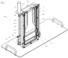
- the third test module 48.3 has a vertical flow channel 76 mounted on the base plate 49 with a transparent front plate 77.
- the flow channel 76 is connected at the bottom to the second connection 50 and at the top via outlet lines 78.1, 78.2 through bores 65.1, 65.2 in the base plate 49 to the first outlet 51 on the underside of the base plate 49.
- the flow channel 76 has guide rails 79.1, 79.2 on its side walls. Test specimens 80.1, 80.2 can be inserted into these. Below the test specimens 80.1, 80.2, a first electrode 81 spans at least partially the cross-section of the flow channel 76.
- the first electrode 81 is a wire held at the two lateral edges of the flow channel by electrically conductive pins 82.1, 82.2, which extend outward through an insulating rear wall 83.
- the flow channel 76 further comprises a second electrode 84. This is an electrically conductive strip, which is attached at the level of the first electrode 81 by means of electrically conductive screws 85.1, 85.2, which extend outward through the rear wall 81.
- the pins 82.1, 82.2 and the screws 85.1, 85.2 form second electrical power connections 86.1, 86.2 for connecting an electrical voltage source.
- a drain valve 87 is arranged, which is aligned with a bore 65.3 of the base plate 49.
- the flow channel 76 has a clamp holder 88, on which a cleaning slide 89 is held on a handle 90, which has a cleaning head 91 with a circumferential rubber lip 92 at the bottom and a handle 93 at the top. of the cleaning slide 89, bubbles can be removed from the walls of the vertical flow channel 76.
- the fourth test module 48.4 has a tube 57 made of a transparent material, held on the base plate 49.
- the tube 57 has the second connection 50 at the first tube end 59.
- the tube widens to a cylindrical first tube section 94 with a larger cross-section.
- the first tube section 94 is followed by a conical transition section 95 and this is followed by a cylindrical second tube section 96 with a smaller diameter.
- This is followed by the second tube end 63 of the tube 57, which is connected via an outlet line 78 through a bore 65 in the base plate 49 to the first outlet 51 on the underside of the base plate 49.
- a first impeller 97 is arranged in the first pipe section 94, and a second impeller 98 is arranged in the second pipe section 96.
- a first sensing device 99 for sensing the rotational speed of the first impeller 97 is arranged next to the first pipe section 94, and a second sensing device 100 for sensing the rotational speed of the second impeller 98 is arranged next to the second pipe section 96.
- the first and second sensing devices 99, 100 are connected to second measurement signal terminals 55.1, 55.2.
- the tube 57 is held in a vertical orientation on the base plate 49 to facilitate venting.
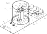
- the fifth test module 48.5 has a top-closed and transparent collecting cylinder 102 with a vertical axis, placed on the edge of the first outlet 51, which is formed as a second opening 101 in the base plate 49.
- a replaceable nozzle 66 is connected to a second connection 50, which is directed vertically upwards above the second opening 101 in the collecting cylinder 102.
- an arm in the collecting cylinder 102 103.1 of a lever 105 pivotally mounted on a support 104 a replaceable impact element 106 is held.
- a force measuring device 107 is supported on one side by an abutment 108 on the support 104 and on the other side by the other arm 103.2 of the lever 105.
- the inlet of the nozzle 66 is connected to the second pressure connection 53, and a vertical tube 109 arranged in the collecting cylinder 102 with an opening at the level of the opening of the nozzle 66 is connected to the second reference pressure connection 54.
- a connector cable is routed from the force measuring device 107 to a connector through an internal cable bushing 74.3 adjacent to the nozzle 66 and cable bushings 74.4, 74.5 on the holder 112. Additional nozzles 66 and impact elements 106 are provided on a holder 112 on the base plate 49.
- the sixth test module 48.6 comprises a transparent cylinder 115 arranged on the base plate 49 with a vertical axis, with the second connection 50 at the lower end. Above this, the cylinder 115 has an outflow opening 116 on the side, to which various interchangeable opening elements 117 can be attached.
- a shaft 118 Arranged laterally next to the cylinder 115 is a shaft 118, open at the top and open toward the outflow opening 116, with a transparent front wall 119.
- the shaft 118 is open at the bottom to the first outlet 51, which is designed as a rectangular second opening 101 in the base plate 49. At the top, the shaft 118 is open above the outflow opening 116.
- a length measuring device 120 with a holder 121 is arranged, which can be inserted into various pairs of grooves 122 at the upper edge of the shaft 118.
- the length measuring device 120 serves to measure the distance of a test liquid emerging from the outlet opening 116 from the upper edge of the shaft 118 at various distances from the outlet opening 116.
- a second pressure port 53 is located at the base of cylinder 115.
- a second reference pressure port 54 is located at a small basin 123, which is separate from cylinder 115 and located on the inside of shaft 118.
- a holder 112 On the base plate 49 there is a holder 112 on which various opening elements 117 or nozzle inserts are mounted, which can be fastened to the outflow opening 116.
- the signal is routed from the length measuring device 120 via a cable to a polygonal socket 74.6 on the top of the holder 112. This socket is wired within the holder 112 to a round socket 74.7, which also serves as the second measurement signal connection 55.
- the sixth test module 48.6 has a drain valve 87 at the lower end of the cylinder 115, which is aligned with a bore 65 in the base plate 49.
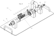
- the seventh test module 48.7 comprises a horizontal Venturi nozzle 124 made of a transparent material, held above the base plate 49, which is connected at one end to the second connection 50. At the other end, the Venturi nozzle 124 is connected to the first outlet 51 via an outlet line 78. Pressure measuring bores are provided at various points on the nozzle and diffuser of the Venturi nozzle 124. These are connected to second pressure and reference pressure connections 53.1 to 53.6, 54 protruding from the outside of the Venturi nozzle. The second reference pressure connection 54 is located at the narrowest point of the Venturi nozzle 124. From the other end, a pressure lance 126 projects through a sealing element 125 into the Venturi nozzle. The pressure lance 126, with its inlet opening 127, can be positioned at various positions in the Venturi nozzle 124. At the other end, it is connected to a second pressure connection 53.7.
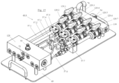
- the eighth test module 48.8 comprises several horizontal, equally long pipes 57.1 to 57.7, which are held parallel to one another on the base plate 49.
- the pipes 57.1 to 57.7 are connected at the first pipe ends to a distribution block 128, which has the second connection 50.
- the pipes 57.1 to 57.7 are connected via hand valves 129.1 to 129.7 to a drain block 130, which is connected to the first outlet 51 via an outlet line 78.
- a second pressure connection 53 is arranged on the distribution block 128, and a second reference pressure connection 54 is arranged on the drain block.
- Pipes 57.1 to 57.7 are designed as follows with and without internals: Pipe 57.1 with large inner diameter and built-in nozzle, pipe 57.2 with large inner diameter and built-in orifice, pipe 57.3 with small inner diameter and built-in nozzle, pipe 57.4 with small inner diameter, S-bend and built-in nozzle, pipe 57.5 with small inner diameter, sharp-edged S-bend and built-in nozzle, pipe 57.6 with small inner diameter, double S-bend and built-in nozzle and pipe 57.7 with small inner diameter, built-in valve and built-in nozzle.
- the ninth test module 48.9 comprises horizontal tubes 57.1, 57.2 and tube bundles 131.1 to 131.4 held side by side on a base plate 49. At one end, the tubes 57.1, 57.2 and tube bundles 131.1 to 131.4 are held on the base plate 49 in a first bearing block 132, which has a separate second connection 50.1 to 50.6 for each tube 57.1, 57.2 and each tube bundle 131.1 to 131.4. At approximately two-thirds of their length, the tubes 57.1, 57.2 and tube bundles 131.1 to 131.4 are held on the base plate 49 in a second bearing block 133, which has a separate second pressure connection 53.1 to 53.6 and a separate first vent valve 134.1 to 134.6 for each tube 57.1, 57.2 and each tube bundle 131.1 to 131.4.
- the tubes 57.1, 57.2 and tube bundles 131.1 to 131.4 are held on the base plate 49 in a third bearing block 135, which has a separate second reference pressure connection 54.1 to 54.6 and a separate second vent valve 136.1 to 136.6 for each tube 57.1, 57.2 and tube bundles 131.1 to 131.4.
- the tube bundle 131.1 with most of the tubes is additionally held at about 40% of its length on the base plate 49 in a fourth bearing block 137, which has a second pressure connection 53.7 and a third vent valve 137.1.
- the other ends of the tubes are located above a rectangular, second opening 101 in the base plate 49, the main direction of expansion of which is perpendicular to the tubes 57.1, 57.2 and which forms the first outlet 51.
- a rear splash guard 138 projects from the base plate 49 from the edge of the second opening 101 opposite the open ends of the tubes 57.1, 57.2 and tube bundles 131.1 to 131.4. This splash guard is inclined towards the tubes. Short lateral splash guards 139.1, 139.2 project vertically from the base plate 49 from the lateral edges of the second opening 101 parallel to the tubes.
- a transparent box is attached to the edge of the second opening 101, which box has rear and lateral splash guards projecting vertically from the base plate 49 from the edge of the second opening 101 opposite the open ends of the tubes and tube bundles and from the lateral edges parallel to the tubes. Above the second opening 101, the box has an upper splash guard. An open-pore foam is attached to the inside of the rear splash guard, which reliably prevents any liquid from splashing back.
- the tenth test module 48.10 has horizontal tubes 57.1 to 57.4 held side by side on a base plate 49. These include a hydraulically A smooth tube 57.1 and a hydraulically rough tube 57.2, which are held at one end in a first bearing block 132 on the base plate 49, which has a separate second connection 50.1, 50.2 for each tube 57.1, 57.2. At approximately 60% of their length, the tubes 57.1, 57.2 are held in a second bearing block 133 on the base plate 49, which has a second pressure connection 53.1, 53.2 and a first vent valve 134.1, 134.2 for each tube 57.1, 57.2.
- the tubes 57.1, 57.2 are held in a third bearing block 135, which has a second reference pressure connection 54.1, 54.2 and a second vent valve 136.1, 136.2 for each tube 57.1, 57.2.
- the other ends of the tubes 57.1, 57.2 are arranged above a rectangular second opening 101 in the base plate 49, the main extension direction of which runs perpendicular to the tubes 57.1, 57.2 and which forms the first outlet 51.
- a rectangular tube 57.3 is arranged on the base plate 49, which has the same hydraulic diameter as the two aforementioned tubes 57.1, 57.2.
- the rectangular tube 57.3 has a second connection 50.3 at one end, a second pressure connection 53.3 at approximately 60% of its length, and a second reference pressure connection 54.3 just before its other end (at approximately 95% of its length).
- the other end of the rectangular tube is arranged above the second opening 101, so that the test fluid can exit from this end of the rectangular tube 57.3 into the second opening 101.
- a fourth tube 57.4 is mounted on the base plate 49 in a groove 140, which has a second connection 50.4 at both ends. Between the two ends, a plurality of second pressure or reference pressure connections 53.1 to 53.7, 54.4, 54.5 protrude from the tube, with adjacent connections being alternately aligned in different directions at acute angles to one another in order to facilitate the attachment of hose couplings to adjacent connections.
- the tube 57.4 is secured by means of clamps 141 and knurled screws. 142 is attached to the channel 140. This makes it easy to detach the pipe 57.4 and insert it into the channel 140 in the reverse orientation.
- the second opening 101 is also enclosed at the edge remote from the pipes 57.1 to 57.4 and at the adjacent lateral edges by splash guards 138, 139.1 and 139.2.
- a transparent box is used as a splash guard, as in the alternative embodiment of FIG. 16 arranged.
- the eleventh test module 48.11 has a horizontal flow channel 143 on the base plate 49 with a front wall 119 made of transparent material.
- the flow channel 143 extends between a first shaft 144 and a second shaft 145.
- the first shaft 144 has the second connection 50 on one side.
- the first shaft 144 is connected to the inlet of the flow channel 143 via a slot nozzle 146 designed as a removable insert, which comprises a horizontal first plate 147 and a second plate 148 inclined relative to it.
- the slot nozzle 146 is fastened in the flow channel 143, for example, by means of screws. By means of the slot nozzle 146, a very rapid flow of the test liquid can be generated in the flow channel 143.
- the other end of the flow channel 143 is connected via the second shaft 145 to a second opening 101 in the base plate 49.
- a second pressure connection 53.1, 53.2 is connected to a bottom wall 149 of the flow channel 143.
- the bottom wall 149 is made of powder-coated sheet steel.
- the second pressure connections 53.1, 53.2 protrude through two holes in the bottom wall into the flow channel 143.
- An additional basin 123 with an overflow, which has the second reference pressure connection 54, is located on the base plate 49.
- various fittings 150 are mounted, which can be inserted into the flow channel 143 and are held therein by means of built-in magnets
- the fixtures 150 are held to the sheet steel base wall 149 by means of built-in magnets.
- Fig. 20 shows a mobile shelf 151 with a shelf frame 152 with rollers 153 and several shelves 154 on which the experimental device 1 and several different experimental modules 48.1 to 48.11 can be stored.
- Modules 48.1 to 48.11 are placed on the main unit 1. The dimensions and markings determine the exact positioning.
- the main unit recognizes the attached module using an RFID identifier and switches the touch panel 16 to the corresponding mode.
- Internet-enabled devices can access the touch panel interface via the internet or a Wi-Fi access point. It is possible to navigate the operator menu independently of the currently displayed interface.
- Operating the main unit via this connection can optionally be specified through programming.
- Operation is via the built-in touch panel 16.
- the speed of the first pump 12 can be controlled. Depending on the experiment, control by pressure or flow rate is also possible.
- the efficiency is improved compared to throttling. This process is more energy-efficient, resulting in lower heat input.
- the main unit 1 has an internally switchable heating device 37.
- a chiller can be connected to cool the water, which can be particularly useful in warmer countries.
- the measurement technology is digitized using the touch panel 16. Measurement values from the tests are stored in memory at the touch of a button. A diagram is generated in most module interfaces.
- a magnetic inductive sensor 28 is used to measure the volume flow. These flow meters have high accuracy and a wide measuring range.
- pressure transducers 30.1 to 30.3 are operated in parallel.
- the pressure transducers for measuring the low pressures are insensitive to the maximum pressure present.
- the software uses the output value to determine which transducer to evaluate.
- pressures must be measured at various points. Up to seven pressure differentials can be measured using eight mechanical pressure connections (14.1 to 14.7, 15). Solenoid valves (31.1 to 31.7) release one of these pressures. This pressure is then applied to pressure transducers (30.1 to 30.7) and can be adopted after a settling time. If multiple pressures need to be measured at a single flow rate during a test, this can also be done in a single measurement sequence.
- Flow rate, temperature, and pressure are measured using the integrated measurement technology of main unit 1. Each measurement point is assigned a measurement time. This data can be saved as a file, allowing separate evaluation on a PC.
- the user interface is designed in such a way that essential relationships can be captured in the display. It is possible to save the user interface with the displayed values as an image.
- All modules have a water connection for water flow. Pressure measurement lines or the connection of additional module-specific measurement equipment depend on the test.
- the experiment is also known as the "Osborne Reynolds experiment.”
- a stream of tin is visualized in a pipe flow. The jet is clearly visible. Above a certain flow velocity, the first turbulences begin to form. These turbulences increase with increasing flow velocity, until ultimately, no ink jet is visible at all.
- the experiment is available in both a standing and a lying setup. Due to space constraints, the lying setup is used.
- a clear pipe bend 64 (coil) is installed at the end of the pipe section. The flow flows through the pipe bend and forms two counter-rotating vortices within the pipe bend.
- Second module (48.2) Measuring the flow profile:
- the fluid flows through a pipe 57. After an inlet section, the flow profile has formed. Essentially, the flow pattern can be divided into laminar and turbulent flow.
- test specimens 80.1, 80.2 can accelerate the flow by narrowing the cross-section or decelerate it by widening the cross-section.
- a cleaning slider 89 can be seen from the top left of the transparent windscreen. Dirt and bubbles adhering to the inside can be removed by inserting it into the channel from above and pulling it across the surfaces.
- the module consists of a large-diameter tube 57 through which the fluid flows. A transition reduces the tube to half its cross-section. This increases the flow velocity by a factor of two.
- the flow velocity is indicated by impellers 97 and 98, which are driven by the flow. These impellers have the same pitch.
- the impeller mounts are also identical.
- the module is used to measure the force of a water jet as it hits a body.
- the deflection of the jet is crucial. The more the jet is deflected, the greater the measured force.
- various impact bodies 106 are provided. These are positioned in the beam using a balance beam 105.
- the balance beam is rotatably mounted, and a force transducer 107 serves as a support on the opposite side of the beam. This force transducer measures the force of the beam.
- the force transducer is protected from overload by a mechanical stop.
- the large nozzle has twice the cross-sectional area of the small one.
- Honeycomb straighteners help create a smooth jet at the nozzle in the short setup.
- the pre-pressure at the nozzle can be measured. This shows which pressure leads to which flow rate and, ultimately, which force is generated.
- the experimental setup is covered by a Plexiglas collecting cylinder 102. This allows the processes to be clearly visible.
- the device demonstrates the outflow from outlet openings 116 under a given water level.
- the discharge is largely determined by the pressure at the opening. This pressure is determined by the height of the water column.
- the water level is automatically adjusted via a control system. The fill level is measured via the water pressure.
- the resulting water jet is a more or less elongated parabola, corresponding to the parabola of projection. This descent of the parabola is measured at specified points using a digital caliper.
- the measured parabola can be compared to a mathematically derived curve.
- the outlet opening is interchangeable. There are four openings in total. The diameter and the inlet of the opening (rounded or sharp-edged) can be varied.
- the seventh module uses a Venturi nozzle to demonstrate the relationship between the conversion of pressure into speed.
- the fluid flows through a Venturi nozzle 124, and the static pressure is measured using pressure measuring holes on the wall.
- the dynamic pressure can also be measured at these points using an adjustable pressure lance 126.
- the measuring points at the nozzle and diffuser have the same diameters so that the pressure recovery in the diffuser can later be compared with the original pressure.
- the flow velocity also depends on the diameter: c ⁇ 1 d 2 It follows: ⁇ p ⁇ c 2 ⁇ 1 d 4
- the nozzle contour is shaped so that the static pressure falls evenly over the length ⁇ p ⁇ L .
- the measuring points are evenly distributed - the pressure falls evenly from measuring point to measuring point.
- the proportionality ⁇ p ⁇ 1 d 4 can be shown so well.
- the Venturi nozzle can be reversed in its design, allowing flow to pass through it in the opposite direction. Higher pressure drops can be demonstrated this way. Deviations from the originally linear curve in the opposite direction indicate separation.
- the module contains 7 didactically consecutive pipe sections 57.1 to 57.7. These are all located between a distribution block 128 and a drain block 130. At the end of these sections, hand valves are installed to open the pipe section to be tested. The pressure loss is measured along the entire pipe section.
- the pressure loss is largely determined by the flow velocity.
- the module is designed to investigate the relationships between pipe friction. It focuses specifically on the use of the Moody diagram, which becomes truly tangible through the use of similarity numbers.
- the Moody diagram is based on dimensionless parameters (Reynolds & pipe friction coefficient) and can therefore be applied to all diameters and flow velocities.
- test sections Pipes and tube bundles 57.1, 57.2, 131.1 to 131.4
- the six test sections are intended to: - Show the transferability of the measured values to the dimensionless key figures.
- - Cover a maximum range in the diagram, since the individual test sections can only show a limited part of the diagram due to the accuracy of the volume flow and pressure measurements. Therefore, there is overlap in the measurements from, for example, ⁇ 1 to ⁇ 2, with a higher Reynolds number being achieved at the larger diameter.
- proportionalities can be shown, e.g.: Laminar: ⁇ p ⁇ V ⁇ ⁇ p ⁇ 1/ d 4 Turbulent: ⁇ p ⁇ V ⁇ 2
- pipe 57.4 Another element is pipe 57.4, which has numerous pressure measurement holes along the inlet section. This is where the pressure loss along the inlet section is measured. This is particularly high at the beginning of the inlet. There are differences in the calming section between laminar and turbulent flow.
- the inlet loss at the constriction can also be measured at both inlets. This is also a frequently encountered case when analyzing losses.
- the very small flow channel 143 is primarily intended as a demonstration device to demonstrate the use and essential interrelationships of various channel installations 150.
- the water levels before and after the channel installation are of interest.
- Two pressure gauge connections are provided for this purpose, allowing the water level to be determined by pressure.
- All of these fixtures are secured in the channel with magnets.
- a steel plate is installed beneath the channel through which the water flows.
- Pressure measurement can be used to measure the water level at the front and rear of the channel.
- the measured values can be exported to a file and used in subsequent calculations. Furthermore, the values can be used for animations on the display.
- Nozzle 146 creates a rushing flow in the front part of the channel. If this rushing flow is slowed down, a lower flow velocity results at a higher water level. This phenomenon is called a jump.
- the critical velocity for this test is given by the Froude number Fr.
- Fr c g ⁇ L
- a nozzle is installed at the beginning of the channel.
- This nozzle has a defined height. This allows the flow velocity in the cross-section to be determined using the measured volume flow.
- the Froude number of the supercritical velocity can be determined from the defined nozzle height and the flow velocity.
- the height of the transition step can be calculated using a set of formulas as a function of the Froude number. The experiment supports this theoretical calculation. Deviations are discussed.
- Pressure measurements are carried out during the tests with various test modules.
- the system for measuring pressures and heating/cooling the test fluid is Fig. 3
- the main components are explained above.
- Fig. 21 The same system is shown during pressure measurement. The lines in which the pressure is present during the measurement are highlighted in color. A differential pressure is always measured, with the lower pressure being present at P8. In the example, the pressure at P3 is measured against P8.
- solenoid valve 33.3 is open, and the remaining solenoid valves 33.1, 33.2, and 33.4 to 33.7, as well as switching valves 39, 41, and 43, are closed.
- Fig. 22 illustrates the venting of the pressure ports.
- the lines through which water flows are highlighted in color.
- pressure port p 6 is vented.
- solenoid valve 33.6 is enabled, and the remaining solenoid valves 33.1 to 33.5 and 33.7 are closed.
- valve 41 is open, and valves 39 and 43 are closed.
- the second pump 35 pumps water. through the open valves 41 and 33.6 as well as a connected module 48, taking air with it in the lines 36 and 32. From the module 48, the water returns to the storage tank 24.
- Fig. 23 illustrates the venting of the pressure sensors. Also in Fig. 23 The lines through which water flows are highlighted in color. For this purpose, switching valves 41 and 43 are open, and switching valve 39 and solenoid valves 33.1 to 33.7 are closed. Via switching valve 43, line 42 is short-circuited between the pressure side p 1 to p 7 and the side with the lower pressure p 8. The water flows through lines 36, 32, 42, and 31, taking with it the air in the lines and pressure sensors 30.1 to 30.3.
- the water is guided from bottom to top in order to reliably vent the pressure transducer chambers.
- Fig. 24 shows the system when heating/cooling the water. Also in Fig. 24 The lines through which the water flows are highlighted in color. The first switching valve 39 is open, and the second switching valve 41 is closed. The second pump 35 pumps the water from the storage tank 24 through line 36 and the heating device 37 and the cooling device 38. The water is heated or cooled and returns to the storage tank 24 through line 36.
- the temperature is controlled while the first pump 12 is running to ensure that the temperature is measured via the temperature sensor 29
Landscapes
- Physics & Mathematics (AREA)
- General Physics & Mathematics (AREA)
- Engineering & Computer Science (AREA)
- Pure & Applied Mathematics (AREA)
- Fluid Mechanics (AREA)
- Mathematical Analysis (AREA)
- Mathematical Optimization (AREA)
- Mathematical Physics (AREA)
- Algebra (AREA)
- Business, Economics & Management (AREA)
- Computational Mathematics (AREA)
- Educational Administration (AREA)
- Educational Technology (AREA)
- Theoretical Computer Science (AREA)
- Investigating Strength Of Materials By Application Of Mechanical Stress (AREA)
- Control Of Positive-Displacement Pumps (AREA)
- Measuring Fluid Pressure (AREA)
Claims (26)
- Dispositif destiné à la mise en œuvre d'essais mécaniques d'écoulement, comportant- un boîtier de table (2) doté d'une paroi de boîtier supérieure horizontale (5) dotée d'une surface de pose (6) sur le côté supérieur et une première ouverture (7) formée dans celle-ci pour le montage d'un module d'essai (48) doté d'une plaque de base (49) et d'un ensemble d'essai disposé sur celle-ci pour des essais mécaniques d'écoulement,- un premier raccord (11) accessible depuis l'extérieur pour un tuyau au niveau d'une paroi de boîtier (10), de sorte que le premier raccord peut être relié au moyen d'un premier tuyau à un deuxième raccord (50) du module d'essai (48) pour l'introduction d'un liquide d'essai dans l'ensemble d'essai lorsque le module d'essai (48) est monté sur la surface de pose (6),- un récipient de stockage (24) en forme de cuvette disposé dans le boîtier de table (2) pour du liquide d'essai, lequel est accessible directement par le haut à travers la première ouverture (7) dans la surface de pose (6), de sorte que du liquide d'essai peut être évacué hors de l'ensemble d'essai vers le récipient de stockage (24) à travers une première évacuation (51) de l'ensemble d'essai au niveau du côté inférieur de la plaque de base (49) lorsque le module d'essai (48) est monté sur la surface de pose (6),- une première pompe (12) disposée dans le boîtier de table (2), laquelle est reliée côté entrée à l'espace intérieur du récipient de stockage (24) et côté sortie au premier raccord (11),- un moteur électrique disposé dans le boîtier de table (2) et couplé à la première pompe (12) et- un système de commande électrique (45) disposé dans le boîtier de table (2) et relié au moteur électrique, lequel est conçu pour régler la vitesse de la première pompe (12).
- Dispositif selon la revendication 1, dans lequel un épaulement intérieur (8) décalé vers le bas par rapport à la surface de pose (6) entoure le bord intérieur de la première ouverture (7), pour l'appui du bord extérieur de la plaque de base (49).
- Dispositif selon la revendication 1 ou 2, dans lequel au moins une couche de mousse à pores ouverts (25, 26) est disposée dans l'espace intérieur du récipient de stockage (24).
- Dispositif selon la revendication 3, dans lequel une première couche de mousse à pores ouverts (25) et sur celle-ci une deuxième couche de mousse à pores ouverts (26) sont disposées dans l'espace intérieur, dans lequel la deuxième couche est plus fine que la première couche et la deuxième mousse à pores ouverts a des pores plus fins que la première mousse à pores ouverts.
- Dispositif selon l'une des revendications 1 à 4, dans lequel un capteur de mesure de flux volumique (28), de préférence un capteur de mesure inductif magnétique, est disposé dans une première conduite (27) entre la première pompe (12) et le premier raccord (11) pour la mesure du flux volumétrique du liquide d'essai.
- Dispositif selon l'une des revendications 1 à 5, dans lequel un premier raccord de pression de référence (15) et au moins un premier raccord de pression (14.1 à 14.7) sont disposés sur une paroi de boîtier (10) du boîtier de table (2) de façon accessible depuis l'extérieur et au moins un capteur de pression (30.1 à 30.3) destiné à mesurer une différence de pression est disposé dans le boîtier de table (2), lequel est relié au premier raccord de pression de référence (15) par le biais d'une deuxième conduite (31) et au premier raccord de pression (14.1 à 14.7) par le biais d'une troisième conduite (32), de sorte que le premier raccord de pression de référence (15) peut être relié à un deuxième raccord de pression de référence (54) d'un ensemble d'essai par le biais d'un deuxième tuyau et le premier raccord de pression (14.1 à 14.7) peut être relié à un deuxième raccord de pression (53) de l'ensemble d'essai par le biais d'un troisième tuyau lorsque le module d'essai (48) est monté sur la surface de pose (6).
- Dispositif selon la revendication 6, dans lequel le capteur de pression (30.1 à 30.3) est relié à différents premiers raccords de pression (14.1 à 14.7) par le biais de soupapes magnétiques (33.1 à 33.7).
- Dispositif selon la revendication 6 ou 7, lequel comporte plusieurs capteurs de pression (30.1 à 30.3) montés en parallèle avec différentes plages de mesure.
- Dispositif selon l'une des revendications 1 à 8, dans lequel un capteur de mesure de température (29) est disposé dans le boîtier de table (2), lequel s'engage dans la première conduite (27) entre la première pompe (12) et le premier raccord (11) ou dans l'espace intérieur du récipient de stockage (24), afin de mesurer la température du liquide d'essai.
- Dispositif selon l'une des revendications 1 à 9, dans lequel un système de chauffage (37) et/ou un système de refroidissement (38) sont disposés dans le boîtier de table (2), lesquels sont intégrés dans une conduite de circulation (36) dans laquelle est disposée une deuxième pompe (35) et/ou dans le récipient de stockage (24), afin de chauffer et/ou de refroidir le liquide d'essai.
- Dispositif selon la revendication 10, dans lequel le système de chauffage (37) est un chauffage à résistance électrique et/ou dans lequel le système de refroidissement (38) est un échangeur de chaleur, lequel est relié à des raccords de liquide de refroidissement (21.1, 21.2) disposés au niveau d'une paroi de boîtier, lesquels sont accessibles depuis l'extérieur, afin de relier celui-ci à un groupe d'eau glacée ou à une autre source de liquide de refroidissement au moyen d'un quatrième et d'un cinquième tuyau.
- Dispositif selon l'une des revendications 1 à 11, lequel comporte un système d'aération des systèmes de mesure de la pression différentielle (30.1 à 30.3), lequel comporte la conduite de circulation (36) et la deuxième pompe (35) disposée dans celle-ci, ainsi que des soupapes magnétiques (33.1 à 33.7) au moyen desquelles le liquide d'essai peut être sélectivement repompé à travers une deuxième conduite (31) entre le capteur de pression (30.1 à 30.3) et le premier raccord de pression de référence (15) et à travers un deuxième tuyau raccordé à celle-ci et l'ensemble d'essai, relié à celui-ci par le biais du deuxième raccord de pression de référence (54), d'un module d'essai (48) monté sur la surface de pose (6) et de là vers le récipient de stockage (24), ou repompé à travers une troisième conduite (32) entre le capteur de pression (30.1 à 30.3) et le premier raccord de pression (14.1 à 14.7) et à travers un troisième tuyau raccordé à celle-ci et l'ensemble d'essai relié à celui-ci par le biais du deuxième raccord de pression (53), vers le récipient de stockage (24).
- Dispositif selon l'une des revendications 1 à 12, dans lequel la première pompe (12) est une pompe centrifuge et/ou dans lequel la première pompe (12) est une pompe submersible et/ou dans lequel la deuxième pompe (35) est une pompe centrifuge et/ou dans lequel la deuxième pompe (35) est une pompe submersible.
- Dispositif selon l'une des revendications 1 à 13, lequel comporte un ordinateur (45) et un écran tactile (16) accessible depuis l'extérieur relié à celui-ci, disposé dans une paroi du boîtier de table (2), dans lequel l'ordinateur (45) est conçu pour afficher des informations sur le dispositif (1) et/ou le module d'essai (48) et/ou les contenus didactiques et/ou le système d'essai et/ou la réalisation des essais et/ou des résultats de mesure et/ou des évaluations de résultats de mesure sur l'écran tactile (16) et/ou pour commander l'aération des systèmes de mesure de la pression différentielle (30.1 à 30.3) et/ou la réalisation d'essais et/ou l'acquisition de résultats de mesure et/ou l'évaluation de résultats de mesure en fonction d'entrées par le biais de l'écran tactile (16).
- Dispositif selon la revendication 14, dans lequel l'ordinateur (45) est capable de se connecter à Internet et/ou lequel comporte un point d'accès WLAN mis en réseau avec l'ordinateur.
- Dispositif selon l'une des revendications 1 à 15, lequel comporte un appareil de lecture (47) relié à l'ordinateur (45) pour une RFID (56), lequel est conçu pour lire un identifiant stocké sur une RFID (56) d'un module d'essai (48) lorsque celui-ci est monté sur la surface de pose, dans lequel l'ordinateur (45) est conçu pour commander le déroulement du programme en fonction de l'identifiant lu à partir de la RFID (56).
- Dispositif selon l'une quelconque des revendications 1 à 16, dans lequel le boîtier de table (2) présente au moins une première borne de signal de mesure (19) sur une paroi de boîtier (10), laquelle est reliée à l'ordinateur (45), accessible depuis l'extérieur et apte à être reliée par le biais d'un premier câble électrique par le biais d'une deuxième borne de signal de mesure à un capteur de mesure électrique (99, 100, 107) sur un module d'essai (48) lorsque celui-ci est monté sur la surface de pose (6).
- Dispositif selon l'une des revendications 1 à 17, dans lequel le boîtier de table (2) comporte une partie inférieure (3) avec la surface de pose (6) sur le côté supérieur et une armoire électrique (4) faisant saillie vers le haut sur le bord arrière de la partie inférieure (3), dans lequel le récipient de stockage (24), la première pompe (12) et le cas échéant la deuxième pompe (35) sont disposés dans la partie inférieure (3), et le système de commande et le cas échéant les capteurs de mesure (28, 29) et le cas échéant l'ordinateur (45) et le cas échéant l'écran tactile (16) sont disposés dans l'armoire électrique (4).
- Dispositif selon la revendication 18, dans lequel le premier raccord (11) et le cas échéant le premier raccord de pression de référence (15) et le premier raccord de pression (14.1 à 14.7) et le cas échéant un premier raccord de signal de mesure (19) accessible depuis l'extérieur pour un capteur de mesure électrique externe (20) et le cas échéant des premières prises de courant électriques accessibles depuis l'extérieur pour un consommateur externe et le cas échéant l'écran tactile (16) sont disposés dans une paroi de boîtier avant (10) de l'armoire électrique (4), laquelle est tournée vers la surface de pose (6).
- Dispositif selon l'une des revendications 1 à 19, dans lequel le boîtier de table (2) comporte des poignées (9) permettant de porter le boîtier de table.
- Module d'essai destiné à la mise en œuvre d'essais mécaniques d'écoulement, comportant• une plaque de base (49) destinée à être montée sur une surface de pose (6) et à recouvrir une première ouverture (7) formée dans celle-ci vers un récipient de stockage (24) d'un dispositif selon la revendication 1,• un ensemble d'essai disposé sur la plaque de base (49) pour des essais mécaniques d'écoulement,• un deuxième raccord (50) pour l'introduction de liquide d'essai dans l'ensemble d'essai au moyen d'un premier tuyau,• une première évacuation (51) pour du liquide d'essai sur le côté inférieur de la plaque de base (49), laquelle est reliée à l'ensemble d'essai par le biais d'un système de guidage de liquide d'essai,• et/ou une deuxième évacuation (52) pour du liquide d'essai au-dessus de la plaque de base (49) pour le raccordement à une conduite de refoulement, et∘ l'un des ensembles d'essai suivants∘ un conduit horizontal (57) maintenu sur la plaque de base, constitué d'un matériau transparent, un système d'alimentation (58) pour un liquide de marquage entre une première extrémité de conduit (59) du conduit (57) et le deuxième raccord (50), un récipient (60) maintenu au-dessus du système d'alimentation (58) de liquide de marquage, une soupape de dosage (61.1) disposée dans une conduite d'alimentation (62) entre le récipient (60) et le système d'alimentation (58), un coude tubulaire (64) relié à la deuxième extrémité de conduit (63) du conduit (57), constitué d'un matériau transparent avec une deuxième évacuation (52) à l'autre extrémité pour le raccordement à une conduite de refoulement ou pour le raccordement à une conduite d'évacuation vers une première évacuation (51) dans un alésage (65) de la plaque de base (49) ;∘ au moins un conduit horizontal (57) maintenu sur la plaque de base, lequel est relié au deuxième raccord (50) au niveau d'une première extrémité de conduit (59) par le biais d'un embout (66) ou d'une entrée à arêtes vives (67) et dont la deuxième extrémité de conduit (63) est reliée à la première évacuation (51) par le biais d'un récipient de collecte (68) pour du liquide d'essai, dans lequel une canule (71) s'engageant dans le conduit (57) peut être déplacée transversalement à la section transversale de conduit dans le récipient de collecte (68) au moyen d'un système de déplacement (69) et la canule (71) est reliée à un deuxième raccord de pression (53) ;∘ un canal d'écoulement vertical (76) maintenu sur la plaque de base, avec une plaque frontale transparente (77), lequel est relié sur le bas au deuxième raccord (50) et sur le haut à la première évacuation (51) par le biais d'au moins une conduite d'évacuation (78.1, 78.2), dans lequel est disposé ou peut être disposé au moins un corps d'essai (80.1, 80.2), dans lequel est disposée une première électrode (81) enjambant au moins partiellement la section transversale du canal d'écoulement (76) sous le corps d'essai (80.1, 80.2) et dans lequel est disposée une deuxième électrode (84), dans lequel la première électrode (81) et la deuxième électrode (84) sont reliées à des deuxièmes prises de courant électriques (86.1, 86.2) pour le raccordement d'une source de tension électrique (HM 250.03) ;∘ un conduit (57) maintenu sur la plaque de base, constitué d'un matériau transparent, lequel présente le deuxième raccord (50) à une première extrémité de conduit (59), suivi d'une première section de conduit (94) avec un diamètre plus grand, suivie d'une section de transition (95) de rétrécissant de façon conique ou avec une autre forme, suivie d'une deuxième section de conduit (96) avec un diamètre plus petit et lequel est relié à la première évacuation (51) à l'autre extrémité par le biais d'une conduite d'évacuation (78), dans lequel une première roue à aubes (97) est disposée dans la première section de conduit (94) et une deuxième roue à aubes (98) est disposée dans la deuxième section de conduit (96), un premier système de détection (99) est disposé à côté de la première section de conduit (94) pour la détection de la vitesse de rotation de la première roue à aubes (97), un deuxième système de détection (100) est disposé à côté de la deuxième section de conduit (96) pour la détection de la vitesse de rotation de la deuxième roue à aubes (98), et les premier et deuxième systèmes de détection (99, 100) sont reliés à des deuxièmes raccords de signal de mesure (55) ;∘ un cylindre de réception (102) fermé sur le dessus et transparent, avec un axe vertical, monté sur le bord de la première évacuation (51) conçue comme une deuxième ouverture (101) de la plaque de base (49), une buse (66) orientée verticalement vers le haut au-dessus de la première ouverture dans le cylindre de réception (102), reliée au deuxième raccord, un élément d'impact (106) maintenu verticalement au-dessus de la buse (66) sur un bras (103.1) d'un levier (105) monté de façon pivotante sur un support (104), un système de mesure de force (107) s'appuyant d'une part sur une butée (108) et d'autre part sur l'autre bras (103.2) du levier (105), dans lequel l'entrée de la buse (66) est reliée au deuxième raccord de pression (53) et le système de mesure de force (107) est relié au deuxième raccord de signal de mesure (55) ;∘ un cylindre transparent (115) disposé avec un axe vertical sur la plaque de base (49), avec le deuxième raccord (50) à l'extrémité inférieure et une ouverture d'écoulement (116) disposée au-dessus, sur le côté où différents éléments d'ouverture (117) peuvent être fixés de façon remplaçable, un puits (118) ouvert sur le haut, disposé latéralement à côté du cylindre (115) et ouvert vers l'ouverture d'écoulement (116), avec une paroi avant (119) au moins transparente, lequel est ouvert sur le bas vers la première évacuation (51) conçue comme une deuxième ouverture (101) dans la plaque de base (49), dans lequel le puits (118) est ouvert sur le haut au-dessus de l'ouverture d'écoulement (116) et il est prévu un système de mesure de longueur (120) monté sur le bord supérieur du puits (118), lequel peut être positionné à différentes distances de l'ouverture d'écoulement (116) pour mesurer la distance entre un jet de liquide d'essai sortant de l'ouverture d'écoulement (116) et le bord supérieur du puits (118), dans lequel le deuxième raccord de pression (53) est disposé en bas sur le cylindre (115) et le deuxième raccord de pression (53) est disposé sur un bassin (123) sur la plaque de base (49) ;∘ une buse Venturi horizontale (124) maintenue au-dessus de la plaque de base (49), constituée d'un matériau transparent, laquelle est reliée par une extrémité au deuxième raccord (50) et par l'autre extrémité à la première évacuation (51) de la plaque de base (49) par le biais d'une conduite d'évacuation (78), dans lequel des alésages de mesure de pression sont prévus à différents endroits de la buse et du diffuseur de la buse Venturi (124), lesquels sont reliés à des deuxièmes raccords de pression et des deuxièmes raccords de pression de référence (53.1 à 53.7, 54) faisant saillie à partir du côté extérieur de la buse Venturi, dans lequel une lance de pression (126) peut être positionnée dans la buse Venturi (124) par l'autre extrémité à travers un élément d'étanchéité (125) et avec l'ouverture d'entrée (127) à différentes positions axiales dans la buse Venturi (124), et la lance de pression (126) est reliée à un deuxième raccord de pression (53.7) par l'autre extrémité ;∘ plusieurs conduits horizontaux de longueur égale (57.1 à 57.7) avec plusieurs composants internes, lesquels sont maintenus parallèlement côte à côte sur la plaque de base (49), lesquels sont sélectionnés de préférence parmi un conduit à grand diamètre intérieur et buse intégrée, un conduit à grand diamètre intérieur et obturateur intégré, un conduit à petit diamètre intérieur et buse intégrée, un conduit à petit diamètre intérieur, courbure en S et buse intégrée, un conduit à petit diamètre intérieur, courbure en S à arêtes vives et buse intégrée, un conduit à petit diamètre intérieur, double courbure en S et buse intégrée et un conduit à petit diamètre intérieur, soupape intégrée et buse intégrée, dans lequel le petit diamètre intérieur est un diamètre intérieur plus petit que le grand diamètre intérieur, dans lequel les conduits (57.1 à 57.7) sont reliés à un bloc de distribution (128) par des premières extrémités de conduit, lequel présente le deuxième raccord (50) et un deuxième raccord de pression (53), et les conduits (57.1 à 57.7) sont reliés à un bloc d'écoulement (130) par le biais de robinets manuels (129.1 à 129.7), lequel présente un deuxième raccord de pression de référence (54) et est relié à la première évacuation (51) dans la plaque de base (49) par le biais d'une conduite d'évacuation (78) ;∘ des conduits horizontaux (57.1, 57.2) et des faisceaux de conduits (131.1 à 131.4) de différents diamètres intérieurs maintenus côte à côte sur la plaque de base (49), lesquels présentent respectivement le deuxième raccord (50.1 à 50.4) à des premières extrémités de conduit et dont les deuxièmes extrémités de conduit débouchent respectivement au-dessus d'une deuxième ouverture (101) formant l'évacuation (51) dans la plaque de base (49), s'étendant transversalement aux conduits, laquelle est encadrée par des parois de protection contre les éclaboussures (138, 139.1, 139.2) s'étendant verticalement à partir de la plaque de base (49) sur le bord éloigné des conduits et faisceaux de conduits et sur des bords parallèles aux conduits et faisceaux de conduits, dans lequel les conduits (57.1, 57.2) et les faisceaux de conduits (131.1 à 131.4) présentent respectivement un deuxième raccord de pression (53.1 à 53.6) et une première soupape d'aération (134.1 à 134.6) à une distance du deuxième raccord (50.1 à 50.6) et un deuxième raccord de pression de référence (54.1 à 54.6) et une deuxième soupape d'aération (136.1 à 136.6) à une autre distance du deuxième raccord et un faisceau de conduits présente le cas échéant un deuxième raccord de pression (53.7) et une troisième soupape d'aération (137) à une distance moins éloignée du deuxième raccord;∘ des conduits horizontaux (57.1 à 57.4) maintenus côte à côte sur la plaque de base (49) comportant un conduit hydrauliquement lisse (57.1), un conduit hydrauliquement rugueux (57.2) et un conduit rectangulaire (57.3), lesquels présentent respectivement un deuxième raccord (50.1 à 50.4) au niveau d'une première extrémité de conduit, un deuxième raccord de pression (53.1 à 53.3) à une distance de celui-ci et un deuxième raccord de pression de référence (54.1 à 54.3) à une autre distance de celui-ci, et un conduit (57.4) doté de plus de trois alésages de mesure de pression le long d'un trajet d'entrée, parmi lesquels les deux alésages situés à l'extérieur sont reliés à un deuxième raccord de pression de référence (54.1, 54.2) et les autres sont reliés respectivement à un deuxième raccord de pression (53.1 à 53.7), dans lequel tous les conduits présentent un deuxième raccord à la première extrémité de conduit et seul le conduit (57.4) doté des plus de trois alésages de mesure de pression présente également un deuxième raccord (50.4) à la deuxième extrémité de conduit et les deuxièmes extrémités de conduit de tous les conduits (57.1 à 57.4) débouchent au-dessus d'une deuxième ouverture (101) formant la première évacuation (51) dans la plaque de base (49), s'étendant transversalement aux conduits, laquelle est encadrée par des parois de protection contre les éclaboussures (138, 139.1, 139.2) s'étendant verticalement à partir de la plaque de base (49) sur le bord éloigné des conduits (57.1 à 57.4) et sur les bords latéraux parallèles aux conduits ;∘ un canal d'écoulement horizontal (143) sur la plaque de base (49) avec au moins une paroi avant (119) constituée d'un matériau transparent, un deuxième raccord (50) à une deuxième du canal d'écoulement (143) et un raccordement à la première évacuation (51) à l'autre extrémité du canal d'écoulement (143), plusieurs composants (150) aptes à être placés dans le canal d'écoulement (143) et à être fixés dans celui-ci au moyen d'aimants, et une buse à fente (146) apte à être montée fixement pour la démonstration de niveaux d'énergie et de pertes ainsi que pour la détermination de débits lors de l'écoulement à travers le canal d'écoulement (143).
- Module d'essai selon la revendication 21, comportant un deuxième raccord de pression de référence (54) et au moins un deuxième raccord de pression (53), lesquels sont reliés à l'ensemble d'essai, et/ou au moins un deuxième raccord de signal de mesure (55), lequel est relié à un capteur de mesure électrique (99, 100, 107) dans la structure d'essai, et/ou des deuxièmes prises de courant électriques (86.1, 86.2) pour le raccordement à une source de tension électrique, lesquelles sont reliées à un consommateur électrique sur la plaque de base (49).
- Module d'essai selon la revendication 21 ou 22, lequel comporte une RFID (56), sur laquelle est stocké un identifiant lisible avec une identification du module d'essai (48).
- Système pour la mise en œuvre d'essais mécaniques d'écoulement, comportant un dispositif (1) selon l'une des revendications 1 à 20 et au moins un module d'essai (48.1 à 48.11) pour la mise en œuvre d'essais mécaniques d'écoulement, comportant• une plaque de base (49) destinée à être montée sur une surface de pose (6) et à recouvrir une première ouverture (7) formée dans celle-ci vers un récipient de stockage (24) d'un dispositif selon la revendication 1,• un ensemble d'essai disposé sur la plaque de base (49) pour des essais mécaniques d'écoulement,• un deuxième raccord (50) pour l'introduction de liquide d'essai dans l'ensemble d'essai au moyen d'un premier tuyau,• une première évacuation (51) pour du liquide d'essai sur le côté inférieur de la plaque de base (49), laquelle est reliée à l'ensemble d'essai par le biais d'un système de guidage de liquide d'essai,• et/ou une deuxième évacuation (52) pour du liquide d'essai au-dessus de la plaque de base (49) pour le raccordement à une conduite de refoulement.
- Système selon la revendication 24, comportant au moins un module d'essai selon l'une des revendications 21 à 23.
- Système selon la revendication 24 ou 25, comportant une étagère déplaçable (151) avec plusieurs fonds d'étagère (154) pour l'entreposage du dispositif (1) et de plusieurs modules d'essai (48.1 à 48.11).
Priority Applications (2)
| Application Number | Priority Date | Filing Date | Title |
|---|---|---|---|
| EP19176748.2A EP3745111B1 (fr) | 2019-05-27 | 2019-05-27 | Dispositif et module d'essai permettant de mettre en oeuvre des essais mécaniques d'écoulement |
| PCT/EP2020/053913 WO2020239274A1 (fr) | 2019-05-27 | 2020-02-14 | Dispositif et module d'essai pour exécuter des essais de la mécanique des fluides |
Applications Claiming Priority (1)
| Application Number | Priority Date | Filing Date | Title |
|---|---|---|---|
| EP19176748.2A EP3745111B1 (fr) | 2019-05-27 | 2019-05-27 | Dispositif et module d'essai permettant de mettre en oeuvre des essais mécaniques d'écoulement |
Publications (3)
| Publication Number | Publication Date |
|---|---|
| EP3745111A1 EP3745111A1 (fr) | 2020-12-02 |
| EP3745111B1 true EP3745111B1 (fr) | 2025-05-21 |
| EP3745111C0 EP3745111C0 (fr) | 2025-05-21 |
Family
ID=66655235
Family Applications (1)
| Application Number | Title | Priority Date | Filing Date |
|---|---|---|---|
| EP19176748.2A Active EP3745111B1 (fr) | 2019-05-27 | 2019-05-27 | Dispositif et module d'essai permettant de mettre en oeuvre des essais mécaniques d'écoulement |
Country Status (2)
| Country | Link |
|---|---|
| EP (1) | EP3745111B1 (fr) |
| WO (1) | WO2020239274A1 (fr) |
Families Citing this family (5)
| Publication number | Priority date | Publication date | Assignee | Title |
|---|---|---|---|---|
| CN112964556B (zh) * | 2021-02-19 | 2022-08-02 | 河南省交通检测技术研究院有限公司 | 一种具有多种检测功能的路面材料强度试验装置 |
| CN113588905B (zh) * | 2021-08-06 | 2023-06-16 | 宁波水表(集团)股份有限公司 | 一种供水管网的水质在线监测系统 |
| CN114061901B (zh) * | 2021-11-18 | 2024-10-01 | 西安热工研究院有限公司 | 一种高压水洞试验装置及其试验方法 |
| CN114577440B (zh) * | 2022-03-11 | 2023-12-15 | 浙江大学 | 堤基管涌生成、发展的物理模型以及监测方法 |
| CN114973879B (zh) * | 2022-06-30 | 2023-08-01 | 黑龙江工程学院 | 一种流体力学实验辅助装置 |
Family Cites Families (3)
| Publication number | Priority date | Publication date | Assignee | Title |
|---|---|---|---|---|
| US3363340A (en) * | 1966-03-10 | 1968-01-16 | Electromatic Mfg Co Inc | Fluid power trainer tray |
| US5324956A (en) * | 1992-10-23 | 1994-06-28 | Gas Research Institute | System for characterizing movement and temperature of fluids |
| DE202015106972U1 (de) | 2015-12-21 | 2017-03-22 | G.U.N.T. Gerätebau GmbH | Versuchsgerät zur Untersuchung von Strömungsfeldern |
-
2019
- 2019-05-27 EP EP19176748.2A patent/EP3745111B1/fr active Active
-
2020
- 2020-02-14 WO PCT/EP2020/053913 patent/WO2020239274A1/fr not_active Ceased
Non-Patent Citations (1)
| Title |
|---|
| G.U.N.T GERÄTEBAU GMBH: "Equipment for engineering education. Fluid mechanics.", 31 December 2018 (2018-12-31), Retrieved from the Internet <URL:https://www.systemes-didactiques.fr/doc/catalogues/GU4-GUNT-GB.pdf> * |
Also Published As
| Publication number | Publication date |
|---|---|
| EP3745111C0 (fr) | 2025-05-21 |
| WO2020239274A1 (fr) | 2020-12-03 |
| EP3745111A1 (fr) | 2020-12-02 |
Similar Documents
| Publication | Publication Date | Title |
|---|---|---|
| EP3745111B1 (fr) | Dispositif et module d'essai permettant de mettre en oeuvre des essais mécaniques d'écoulement | |
| DE69118686T2 (de) | Verbesserte zwei- und dreiphasenströmungsmessung | |
| EP0582082B1 (fr) | Procédé pour déterminer la viscosité de liquides et utilisation d'un dispositif mettant en oeuvre ce procédé | |
| DE2812715A1 (de) | Verfahren und vorrichtung fuer die bestimmung der volumendurchsaetze jeder phase in einer zweiphasigen mischung | |
| DE4210845A1 (de) | Vorrichtung zur messung der viskositaet einer fluessigkeit | |
| EP0025921B1 (fr) | Dispositif pour mesurer la tension de surface | |
| DE112023001795T5 (de) | Vorrichtung zur Messung der desorbierten Gasmenge und Messverfahren | |
| DE102010000755B4 (de) | Anordnung zur Messung der Viskosität einer gleichmäßig temperierten Flüssigkeit | |
| DE2405786C3 (de) | Meßeinrichtungen zur Gasstrommessung in Gasabsaugeleitungen | |
| EP0853754B1 (fr) | Procede et dispositif de mesure de la pression hydrostatique, en particulier de celle des eaux souterraines | |
| DE102011050716B4 (de) | Verfahren und Vorrichtung zur Online-Messung der Viskosität eines Fluids | |
| EP3247496B1 (fr) | Dispositif d'aspiration comportant un système d'aspiration régulé | |
| DE2115364A1 (de) | Mengenstrommeßgerät | |
| DE10162286B4 (de) | Vorrichtung zur Bestimmung des Volumens eines Gases bei Umgebungsdruck | |
| DE10249957A1 (de) | Vorrichtung und Verfahren zur Bestimmung des Luftgehalts und des Luftabscheideverhaltens von Ölen | |
| DE102005014429B3 (de) | Verfahren zur Überprüfung der Durchgängigkeit von langgestreckten Hohlkörpern, insbesondere von Endoskopkanälen, und Vorrichtung zur Durchführung des Verfahrens | |
| DE202012007107U1 (de) | Kalibrieranlage für Messsonde im Bereich der Messtechnik der Gas-Flüssigkeits-Zweiphasenströmung | |
| DE202019101690U1 (de) | Messen von Prozessgrößen von Druckluft | |
| DE19809370C2 (de) | Beprobungsrohrsystem | |
| EP1772709A2 (fr) | Dispositif de mesure, en particulier destiné à la mesure de volumes de drainage de machines à papier | |
| DE19850444C2 (de) | Verfahren zur Analytik strömender Flüssigkeiten und Vorrichtung zu seiner Durchführung | |
| DE3337149A1 (de) | Lehrgeraet fuer regelungstechnik | |
| DE2428466A1 (de) | Verfahren und vorrichtung zur regelung des fluiddruckes bei der teilchenuntersuchung | |
| DE202025101345U1 (de) | Strömungsgeschwindigkeitsmessvorrichtung für Rauchgassystem | |
| DE19810400A1 (de) | Durchflußzelle |
Legal Events
| Date | Code | Title | Description |
|---|---|---|---|
| PUAI | Public reference made under article 153(3) epc to a published international application that has entered the european phase |
Free format text: ORIGINAL CODE: 0009012 |
|
| STAA | Information on the status of an ep patent application or granted ep patent |
Free format text: STATUS: THE APPLICATION HAS BEEN PUBLISHED |
|
| AK | Designated contracting states |
Kind code of ref document: A1 Designated state(s): AL AT BE BG CH CY CZ DE DK EE ES FI FR GB GR HR HU IE IS IT LI LT LU LV MC MK MT NL NO PL PT RO RS SE SI SK SM TR |
|
| AX | Request for extension of the european patent |
Extension state: BA ME |
|
| STAA | Information on the status of an ep patent application or granted ep patent |
Free format text: STATUS: REQUEST FOR EXAMINATION WAS MADE |
|
| 17P | Request for examination filed |
Effective date: 20210601 |
|
| RAX | Requested extension states of the european patent have changed |
Extension state: BA Payment date: 20210601 Extension state: ME Payment date: 20210601 |
|
| RBV | Designated contracting states (corrected) |
Designated state(s): AL AT BE BG CH CY CZ DE DK EE ES FI FR GB GR HR HU IE IS IT LI LT LU LV MC MK MT NL NO PL PT RO RS SE SI SK SM TR |
|
| STAA | Information on the status of an ep patent application or granted ep patent |
Free format text: STATUS: EXAMINATION IS IN PROGRESS |
|
| 17Q | First examination report despatched |
Effective date: 20221114 |
|
| GRAP | Despatch of communication of intention to grant a patent |
Free format text: ORIGINAL CODE: EPIDOSNIGR1 |
|
| STAA | Information on the status of an ep patent application or granted ep patent |
Free format text: STATUS: GRANT OF PATENT IS INTENDED |
|
| GRAS | Grant fee paid |
Free format text: ORIGINAL CODE: EPIDOSNIGR3 |
|
| GRAA | (expected) grant |
Free format text: ORIGINAL CODE: 0009210 |
|
| STAA | Information on the status of an ep patent application or granted ep patent |
Free format text: STATUS: THE PATENT HAS BEEN GRANTED |
|
| INTG | Intention to grant announced |
Effective date: 20250319 |
|
| AK | Designated contracting states |
Kind code of ref document: B1 Designated state(s): AL AT BE BG CH CY CZ DE DK EE ES FI FR GB GR HR HU IE IS IT LI LT LU LV MC MK MT NL NO PL PT RO RS SE SI SK SM TR |
|
| REG | Reference to a national code |
Ref country code: GB Ref legal event code: FG4D Free format text: NOT ENGLISH |
|
| REG | Reference to a national code |
Ref country code: CH Ref legal event code: EP |
|
| REG | Reference to a national code |
Ref country code: DE Ref legal event code: R096 Ref document number: 502019013363 Country of ref document: DE |
|
| REG | Reference to a national code |
Ref country code: IE Ref legal event code: FG4D Free format text: LANGUAGE OF EP DOCUMENT: GERMAN |
|
| U01 | Request for unitary effect filed |
Effective date: 20250521 |
|
| U07 | Unitary effect registered |
Designated state(s): AT BE BG DE DK EE FI FR IT LT LU LV MT NL PT RO SE SI Effective date: 20250528 |
|
| U20 | Renewal fee for the european patent with unitary effect paid |
Year of fee payment: 7 Effective date: 20250604 |
|
| PG25 | Lapsed in a contracting state [announced via postgrant information from national office to epo] |
Ref country code: ES Free format text: LAPSE BECAUSE OF FAILURE TO SUBMIT A TRANSLATION OF THE DESCRIPTION OR TO PAY THE FEE WITHIN THE PRESCRIBED TIME-LIMIT Effective date: 20250521 |
|
| PG25 | Lapsed in a contracting state [announced via postgrant information from national office to epo] |
Ref country code: NO Free format text: LAPSE BECAUSE OF FAILURE TO SUBMIT A TRANSLATION OF THE DESCRIPTION OR TO PAY THE FEE WITHIN THE PRESCRIBED TIME-LIMIT Effective date: 20250821 Ref country code: GR Free format text: LAPSE BECAUSE OF FAILURE TO SUBMIT A TRANSLATION OF THE DESCRIPTION OR TO PAY THE FEE WITHIN THE PRESCRIBED TIME-LIMIT Effective date: 20250822 |
|
| PG25 | Lapsed in a contracting state [announced via postgrant information from national office to epo] |
Ref country code: PL Free format text: LAPSE BECAUSE OF FAILURE TO SUBMIT A TRANSLATION OF THE DESCRIPTION OR TO PAY THE FEE WITHIN THE PRESCRIBED TIME-LIMIT Effective date: 20250521 |
|
| PG25 | Lapsed in a contracting state [announced via postgrant information from national office to epo] |
Ref country code: HR Free format text: LAPSE BECAUSE OF FAILURE TO SUBMIT A TRANSLATION OF THE DESCRIPTION OR TO PAY THE FEE WITHIN THE PRESCRIBED TIME-LIMIT Effective date: 20250521 |
|
| PG25 | Lapsed in a contracting state [announced via postgrant information from national office to epo] |
Ref country code: RS Free format text: LAPSE BECAUSE OF FAILURE TO SUBMIT A TRANSLATION OF THE DESCRIPTION OR TO PAY THE FEE WITHIN THE PRESCRIBED TIME-LIMIT Effective date: 20250821 |
|
| PG25 | Lapsed in a contracting state [announced via postgrant information from national office to epo] |
Ref country code: IS Free format text: LAPSE BECAUSE OF FAILURE TO SUBMIT A TRANSLATION OF THE DESCRIPTION OR TO PAY THE FEE WITHIN THE PRESCRIBED TIME-LIMIT Effective date: 20250921 |
|
| REG | Reference to a national code |
Ref country code: CH Ref legal event code: H13 Free format text: ST27 STATUS EVENT CODE: U-0-0-H10-H13 (AS PROVIDED BY THE NATIONAL OFFICE) Effective date: 20251223 |
|
| PG25 | Lapsed in a contracting state [announced via postgrant information from national office to epo] |
Ref country code: SM Free format text: LAPSE BECAUSE OF FAILURE TO SUBMIT A TRANSLATION OF THE DESCRIPTION OR TO PAY THE FEE WITHIN THE PRESCRIBED TIME-LIMIT Effective date: 20250521 |
|
| PG25 | Lapsed in a contracting state [announced via postgrant information from national office to epo] |
Ref country code: CH Free format text: LAPSE BECAUSE OF NON-PAYMENT OF DUE FEES Effective date: 20250531 |
|
| PG25 | Lapsed in a contracting state [announced via postgrant information from national office to epo] |
Ref country code: CZ Free format text: LAPSE BECAUSE OF FAILURE TO SUBMIT A TRANSLATION OF THE DESCRIPTION OR TO PAY THE FEE WITHIN THE PRESCRIBED TIME-LIMIT Effective date: 20250521 |
|
| PG25 | Lapsed in a contracting state [announced via postgrant information from national office to epo] |
Ref country code: SK Free format text: LAPSE BECAUSE OF FAILURE TO SUBMIT A TRANSLATION OF THE DESCRIPTION OR TO PAY THE FEE WITHIN THE PRESCRIBED TIME-LIMIT Effective date: 20250521 |
|
| PG25 | Lapsed in a contracting state [announced via postgrant information from national office to epo] |
Ref country code: MC Free format text: LAPSE BECAUSE OF FAILURE TO SUBMIT A TRANSLATION OF THE DESCRIPTION OR TO PAY THE FEE WITHIN THE PRESCRIBED TIME-LIMIT Effective date: 20250521 |
|
| PLBE | No opposition filed within time limit |
Free format text: ORIGINAL CODE: 0009261 |
|
| STAA | Information on the status of an ep patent application or granted ep patent |
Free format text: STATUS: NO OPPOSITION FILED WITHIN TIME LIMIT |
|
| REG | Reference to a national code |
Ref country code: CH Ref legal event code: L10 Free format text: ST27 STATUS EVENT CODE: U-0-0-L10-L00 (AS PROVIDED BY THE NATIONAL OFFICE) Effective date: 20260402 |
|
| PG25 | Lapsed in a contracting state [announced via postgrant information from national office to epo] |
Ref country code: IE Free format text: LAPSE BECAUSE OF NON-PAYMENT OF DUE FEES Effective date: 20250527 |
|
| 26N | No opposition filed |
Effective date: 20260224 |