EP3745224A1 - Zusammenarbeit zwischen einem roboter und einem bediener zur veränderung eines werkstücks - Google Patents
Zusammenarbeit zwischen einem roboter und einem bediener zur veränderung eines werkstücks Download PDFInfo
- Publication number
- EP3745224A1 EP3745224A1 EP20176600.3A EP20176600A EP3745224A1 EP 3745224 A1 EP3745224 A1 EP 3745224A1 EP 20176600 A EP20176600 A EP 20176600A EP 3745224 A1 EP3745224 A1 EP 3745224A1
- Authority
- EP
- European Patent Office
- Prior art keywords
- robot
- operator
- processing unit
- carried out
- collision
- Prior art date
- Legal status (The legal status is an assumption and is not a legal conclusion. Google has not performed a legal analysis and makes no representation as to the accuracy of the status listed.)
- Granted
Links
Images


Classifications
-
- G—PHYSICS
- G05—CONTROLLING; REGULATING
- G05B—CONTROL OR REGULATING SYSTEMS IN GENERAL; FUNCTIONAL ELEMENTS OF SUCH SYSTEMS; MONITORING OR TESTING ARRANGEMENTS FOR SUCH SYSTEMS OR ELEMENTS
- G05B19/00—Program-control systems
- G05B19/02—Program-control systems electric
- G05B19/18—Numerical control [NC], i.e. automatically operating machines, in particular machine tools, e.g. in a manufacturing environment, so as to execute positioning, movement or co-ordinated operations by means of program data in numerical form
- G05B19/406—Numerical control [NC], i.e. automatically operating machines, in particular machine tools, e.g. in a manufacturing environment, so as to execute positioning, movement or co-ordinated operations by means of program data in numerical form characterised by monitoring or safety
- G05B19/4061—Avoiding collision or forbidden zones
-
- B—PERFORMING OPERATIONS; TRANSPORTING
- B25—HAND TOOLS; PORTABLE POWER-DRIVEN TOOLS; MANIPULATORS
- B25J—MANIPULATORS; CHAMBERS PROVIDED WITH MANIPULATION DEVICES
- B25J9/00—Program-controlled manipulators
- B25J9/16—Program controls
- B25J9/1674—Program controls characterised by safety, monitoring, diagnostic
- B25J9/1676—Avoiding collision or forbidden zones
-
- B—PERFORMING OPERATIONS; TRANSPORTING
- B25—HAND TOOLS; PORTABLE POWER-DRIVEN TOOLS; MANIPULATORS
- B25J—MANIPULATORS; CHAMBERS PROVIDED WITH MANIPULATION DEVICES
- B25J9/00—Program-controlled manipulators
- B25J9/16—Program controls
- B25J9/1694—Program controls characterised by use of sensors other than normal servo-feedback from position, speed or acceleration sensors, perception control, multi-sensor controlled systems, sensor fusion
- B25J9/1697—Vision controlled systems
-
- G—PHYSICS
- G05—CONTROLLING; REGULATING
- G05B—CONTROL OR REGULATING SYSTEMS IN GENERAL; FUNCTIONAL ELEMENTS OF SUCH SYSTEMS; MONITORING OR TESTING ARRANGEMENTS FOR SUCH SYSTEMS OR ELEMENTS
- G05B2219/00—Program-control systems
- G05B2219/30—Nc systems
- G05B2219/40—Robotics, robotics mapping to robotics vision
- G05B2219/40202—Human robot coexistence
Definitions
- the invention relates to the collaboration of an operator with a robot with a view to manufacturing or modifying a part, in particular an aeronautical part, for example a turbomachine.
- the manufacture of aeronautical parts requires the intervention of an operator.
- This operator can be assisted by a robot to perform specific operations.
- an operator makes holes in a part and the robot intervenes on each hole in order to perform a specific operation on each hole.
- Such an operation is, for example, pinning, fitting a fastener, deburring, etc.
- the robot is manipulated according to programmed actions and the operator must perform all his own actions according to the same sequence as the robot without forgetting or reversing the risk that the robot can no longer follow the operator.
- the operator must drill these holes according to the pinning scheme programmed in the robot. If the operator does not respect this diagram, the robot will wait in front of the position of the expected hole until it is drilled. This results in wasted manufacturing time and can lead to manufacturing errors.
- the figure 1 illustrates an environment in which an operator O and a robot R collaborate on the modification of a part 1.
- a part is typically an aeronautical part, for example of a turbomachine of an aircraft, for example:
- the part 1 is for example positioned on a work bench 2 so as to be accessible by the robot R so that the latter performs an operation on the part. The therefore serves as a support for the part.
- the robot R is for example a 5/6/7 axis robot of known type and will not be described in more detail because it is known to those skilled in the art.
- the robot R comprises an arm 3 articulated from its support 4 and comprises at its free end 5 an effector 6 or tool holder. The effector and the tool holder are chosen according to the operation to be performed on the part.
- the operator O is equipped with a tool 7 also chosen according to the operation to be carried out: a drill for a hole for example.
- the R robot can perform one of the following operations: deburring, pinning, riveting, bolting. These operations can be combined for the same part, namely, for example, that a hole in a part requires the installation of a rivet while another hole requires the installation of a pin.
- a shooting system 8 is arranged close to the part 1, above or to the side in order to allow the acquisition of an image of the part being modified for the purposes of comparison with a model of a room. Alternatively, the shooting system can be positioned on the robot R.
- the shooting system 8 is a camera with a field of view large enough to observe the chosen working area.
- a processing unit 9 is connected to the robot R, the processing unit 9 and the robot R for this reason each comprising a communication interface 10, 11.
- the communication between the robot can be wired or wireless.
- the shooting system 8 is connected to the processing unit 9.
- the processing unit 9 comprises a memory 12 allowing the storage of one or more model (s) of part according to the desired modifications. For example, when it comes to performing operations in holes performed by an operator, the model is a part on which the holes in which an operation is to be performed are located. In addition, depending on the different models, trajectories to be followed by the robot are also stored.
- a proximity, force or collision sensor (s) 13 are placed on the robot R or well in the environment of intervention of the latter. Such sensors 13 make it possible, where appropriate, to control the robot R so that it slows down or even stops as a function of the proximity of the robot R to the operator.
- visual or audible alarm type devices 14 may also be present to alert, for example, the operator of a danger.
- a user interface 15 is connected to the processing unit 9 and allows an operator O to configure the robot R, load new models M of the part.
- the user interface comprises a screen and a keyboard, for example, but may consist of a touchscreen tablet or equivalent.
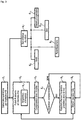
- the processing unit also comprises a processor 16 configured to implement a method for modifying the state of a part which will be described below and in relation to the figures 2 and 3 .
- the robot is positioned in the working environment (step E0). This positioning consists first of all in the operator choosing a work zone (step E01). It is a question here of defining via the user interface 15 the zone on which the robot R will intervene. In particular, the operator, via the user interface 15 can indicate to the robot its future work zone (at the bottom of the room, to the left, to the right, to the center, etc.).
- the robot positions itself at a distance in front of this zone, allowing it to visualize it correctly in order to detect the targeted elements.
- the robot R is moved or moves itself in front of this zone or else to a place from which it can access the work zone (step E02). This movement is controlled remotely via the user interface.
- the robot R When the robot R is positioned at the level of the work zone, the latter performs a complete survey (step E03) of the part, locating itself by means of marks arranged on the part. This flyover allows the robot to have an exact delimitation of its work zone. These marks can take several forms and can be positioned in several strategic places of the part. For a square room, for example, it can be considered that marks placed at the four corners of the room are sufficient.
- modification operations can begin.
- an operator O must drill several holes in a part using a drill for example and the robot must perform a complementary operation in each hole made by the operator O.
- the robot R therefore collaborates with operator O to modify the state of the part.
- the operations of the operator and of the robot R can be varied and the method can be applied to all collaborations requiring both operations performed by the operator O and by the robot R at the same places of the piece or not.
- An operator begins by drilling one or more holes in the part (step E1) and a detection of the drilling of a hole is carried out (step E2). This detection consists in acquiring (step E21) images of the part in order to evaluate whether its state is modified.
- the acquisition can be continuous or carried out at a well chosen frequency.
- the acquisition is implemented by means of the shooting system 8.
- step E5 it is evaluated whether in the hole which has just been made the robot R must perform an operation complementary to that of the operator O (steps E3 and E4) and if this is the case, the robot R is commanded (step E5) so that it performs the operation complementary predefined in the hole which has been detected otherwise the robot R waits (step E6) for a hole to be drilled again.
- the acquired image (s) are compared with a part model comprising the part as it is to be modified.
- the processing unit compares the image acquired by the imaging system 8 and compares it with a theoretical 3D model of the part. The differences are highlighted and the information of a difference between the image and the model is obtained.
- the modification to be made by the robot where operator O has modified the part is preprogrammed in advance and will not be detailed here. Also, to reach the ideal position for performing the operation, the robot R follows a predetermined path in advance. The operations to be performed as well as the trajectories are stored in the memory 12 of the processing unit 9. The predetermined trajectory depends on the environment for the robot R to reach the position and is determined taking into account the information from the sensors 13 in order to to avoid any collisions. The robot R therefore needs the coordinate of the position as well as the type of operation to be performed on this position. After carrying out the operation, the robot goes into a position waiting for a new hole to be drilled. This standby position is also reached if after the hole has been detected it is not necessary for an additional operation to be performed.
- the movements of the robot R are monitored (step E7) in order to avoid a collision between the operator and the robot R.
- the robot R can either stop (step E8) or slow down its movement (step E9).
- an audible or visual signal can be emitted (step E10) to alert the operator that there is a danger.
- the robot can adapt its displacement in order to avoid the collision (step E11).
Landscapes
- Engineering & Computer Science (AREA)
- Robotics (AREA)
- Mechanical Engineering (AREA)
- Human Computer Interaction (AREA)
- Manufacturing & Machinery (AREA)
- Physics & Mathematics (AREA)
- General Physics & Mathematics (AREA)
- Automation & Control Theory (AREA)
- Manipulator (AREA)
- User Interface Of Digital Computer (AREA)
- Numerical Control (AREA)
Applications Claiming Priority (1)
| Application Number | Priority Date | Filing Date | Title |
|---|---|---|---|
| FR1905571A FR3096599B1 (fr) | 2019-05-27 | 2019-05-27 | Collaboration d'un robot et d'un opérateur en vue de modifier une pièce |
Publications (2)
| Publication Number | Publication Date |
|---|---|
| EP3745224A1 true EP3745224A1 (de) | 2020-12-02 |
| EP3745224B1 EP3745224B1 (de) | 2025-10-15 |
Family
ID=67742796
Family Applications (1)
| Application Number | Title | Priority Date | Filing Date |
|---|---|---|---|
| EP20176600.3A Active EP3745224B1 (de) | 2019-05-27 | 2020-05-26 | Zusammenarbeit zwischen einem roboter und einem bediener zur veränderung eines werkstücks |
Country Status (2)
| Country | Link |
|---|---|
| EP (1) | EP3745224B1 (de) |
| FR (1) | FR3096599B1 (de) |
Cited By (1)
| Publication number | Priority date | Publication date | Assignee | Title |
|---|---|---|---|---|
| EP4035846A1 (de) * | 2021-02-01 | 2022-08-03 | The Boeing Company | Roboterfertigungssysteme und -verfahren |
Citations (2)
| Publication number | Priority date | Publication date | Assignee | Title |
|---|---|---|---|---|
| EP2380709A2 (de) * | 2010-04-22 | 2011-10-26 | Sick AG | 3D-Sicherheitsvorrichtung und Verfahren zur Absicherung und Bedienung mindestens einer Maschine |
| EP3479971A1 (de) * | 2017-11-03 | 2019-05-08 | Nederlandse Organisatie voor toegepast- natuurwetenschappelijk onderzoek TNO | Verfahren zur durchführung der montage eines objekts und montagesystem |
-
2019
- 2019-05-27 FR FR1905571A patent/FR3096599B1/fr active Active
-
2020
- 2020-05-26 EP EP20176600.3A patent/EP3745224B1/de active Active
Patent Citations (2)
| Publication number | Priority date | Publication date | Assignee | Title |
|---|---|---|---|---|
| EP2380709A2 (de) * | 2010-04-22 | 2011-10-26 | Sick AG | 3D-Sicherheitsvorrichtung und Verfahren zur Absicherung und Bedienung mindestens einer Maschine |
| EP3479971A1 (de) * | 2017-11-03 | 2019-05-08 | Nederlandse Organisatie voor toegepast- natuurwetenschappelijk onderzoek TNO | Verfahren zur durchführung der montage eines objekts und montagesystem |
Cited By (3)
| Publication number | Priority date | Publication date | Assignee | Title |
|---|---|---|---|---|
| EP4035846A1 (de) * | 2021-02-01 | 2022-08-03 | The Boeing Company | Roboterfertigungssysteme und -verfahren |
| US20220241978A1 (en) * | 2021-02-01 | 2022-08-04 | The Boeing Company | Robotic manufacturing systems and methods |
| US12151383B2 (en) | 2021-02-01 | 2024-11-26 | The Boeing Company | Robotic manufacturing systems and methods |
Also Published As
| Publication number | Publication date |
|---|---|
| FR3096599A1 (fr) | 2020-12-04 |
| FR3096599B1 (fr) | 2021-06-11 |
| EP3745224B1 (de) | 2025-10-15 |
Similar Documents
| Publication | Publication Date | Title |
|---|---|---|
| CN101512452B (zh) | 基于摄像机监控具有移动机器部件的机器以防碰撞 | |
| US10378353B2 (en) | Robot automated mining | |
| JP5883881B2 (ja) | ゾーンを監視する方法及び装置 | |
| JP5229253B2 (ja) | ロボットシステム及びロボット装置並びにワーク取り出し方法 | |
| US20210146546A1 (en) | Method to control a robot in the presence of human operators | |
| JP2018024055A (ja) | 工作機械の工具の異常検知装置及び方法 | |
| JP7119532B2 (ja) | 生産性向上支援システムおよび生産性向上支援プログラム | |
| US8767070B2 (en) | Configuration module for a surveillance system, surveillance system, method for configuring the surveillance system, and computer program | |
| US9703290B1 (en) | Method for operating machines on worksites | |
| JP2020067776A (ja) | 工作機械の異常診断システム、異常診断方法、異常診断プログラム | |
| EP2242621A2 (de) | Verfahren zum training eines roboters oder einer ähnlichen vorrichtung sowie vorrichtung zur anwendung dieses verfahrens | |
| EP3267680A1 (de) | Vorrichtung zur überwachung von fahrzeugumgebungen | |
| US9458903B2 (en) | System and method for monitoring a brake system of a mining machine | |
| CN103914035A (zh) | 用于机器人组的可配置的安全监控装置和方法 | |
| EP3745224B1 (de) | Zusammenarbeit zwischen einem roboter und einem bediener zur veränderung eines werkstücks | |
| CN119981592B (zh) | 一种车辆控制方法及车辆 | |
| CN114693771A (zh) | 对人执行的任务用计算机视觉监测制造操作的方法和系统 | |
| CN109500657A (zh) | 一种基于视觉的断刀检测方法及系统 | |
| EP4117867A1 (de) | Verfahren zur automatischen durchführung einer operation an einem objekt mit einem von einem mehrgelenkigen system getragenen werkzeug | |
| JP2006321001A (ja) | 自律移動ロボット及びその移動状況記録システム | |
| JP2023113045A (ja) | 工作機械の加工異常検知方法及び加工異常検知装置 | |
| EP4015715B1 (de) | Betriebsaufzeichnungs- und analysesystem für baumaschinen | |
| CN111590574B (zh) | 一种高智能机器人防盗方法及系统 | |
| JP2002137148A (ja) | ツール状況検出器及びこれを用いたatc自動復帰システム及び表示システム | |
| JP2021059869A (ja) | 情報処理装置 |
Legal Events
| Date | Code | Title | Description |
|---|---|---|---|
| PUAI | Public reference made under article 153(3) epc to a published international application that has entered the european phase |
Free format text: ORIGINAL CODE: 0009012 |
|
| STAA | Information on the status of an ep patent application or granted ep patent |
Free format text: STATUS: REQUEST FOR EXAMINATION WAS MADE |
|
| 17P | Request for examination filed |
Effective date: 20200526 |
|
| AK | Designated contracting states |
Kind code of ref document: A1 Designated state(s): AL AT BE BG CH CY CZ DE DK EE ES FI FR GB GR HR HU IE IS IT LI LT LU LV MC MK MT NL NO PL PT RO RS SE SI SK SM TR |
|
| AX | Request for extension of the european patent |
Extension state: BA ME |
|
| STAA | Information on the status of an ep patent application or granted ep patent |
Free format text: STATUS: EXAMINATION IS IN PROGRESS |
|
| 17Q | First examination report despatched |
Effective date: 20220701 |
|
| GRAP | Despatch of communication of intention to grant a patent |
Free format text: ORIGINAL CODE: EPIDOSNIGR1 |
|
| STAA | Information on the status of an ep patent application or granted ep patent |
Free format text: STATUS: GRANT OF PATENT IS INTENDED |
|
| INTG | Intention to grant announced |
Effective date: 20250630 |
|
| GRAS | Grant fee paid |
Free format text: ORIGINAL CODE: EPIDOSNIGR3 |
|
| GRAA | (expected) grant |
Free format text: ORIGINAL CODE: 0009210 |
|
| STAA | Information on the status of an ep patent application or granted ep patent |
Free format text: STATUS: THE PATENT HAS BEEN GRANTED |
|
| AK | Designated contracting states |
Kind code of ref document: B1 Designated state(s): AL AT BE BG CH CY CZ DE DK EE ES FI FR GB GR HR HU IE IS IT LI LT LU LV MC MK MT NL NO PL PT RO RS SE SI SK SM TR |
|
| REG | Reference to a national code |
Ref country code: GB Ref legal event code: FG4D Free format text: NOT ENGLISH Ref country code: CH Ref legal event code: F10 Free format text: ST27 STATUS EVENT CODE: U-0-0-F10-F00 (AS PROVIDED BY THE NATIONAL OFFICE) Effective date: 20251015 |
|
| REG | Reference to a national code |
Ref country code: IE Ref legal event code: FG4D Free format text: LANGUAGE OF EP DOCUMENT: FRENCH |
|
| REG | Reference to a national code |
Ref country code: DE Ref legal event code: R096 Ref document number: 602020060389 Country of ref document: DE |
|
| REG | Reference to a national code |
Ref country code: NL Ref legal event code: MP Effective date: 20251015 |
|
| REG | Reference to a national code |
Ref country code: AT Ref legal event code: MK05 Ref document number: 1847481 Country of ref document: AT Kind code of ref document: T Effective date: 20251015 |
|
| PG25 | Lapsed in a contracting state [announced via postgrant information from national office to epo] |
Ref country code: NL Free format text: LAPSE BECAUSE OF FAILURE TO SUBMIT A TRANSLATION OF THE DESCRIPTION OR TO PAY THE FEE WITHIN THE PRESCRIBED TIME-LIMIT Effective date: 20251015 |
|
| PG25 | Lapsed in a contracting state [announced via postgrant information from national office to epo] |
Ref country code: ES Free format text: LAPSE BECAUSE OF FAILURE TO SUBMIT A TRANSLATION OF THE DESCRIPTION OR TO PAY THE FEE WITHIN THE PRESCRIBED TIME-LIMIT Effective date: 20251015 |
|
| REG | Reference to a national code |
Ref country code: LT Ref legal event code: MG9D |
|
| PG25 | Lapsed in a contracting state [announced via postgrant information from national office to epo] |
Ref country code: NO Free format text: LAPSE BECAUSE OF FAILURE TO SUBMIT A TRANSLATION OF THE DESCRIPTION OR TO PAY THE FEE WITHIN THE PRESCRIBED TIME-LIMIT Effective date: 20260115 |
|
| PG25 | Lapsed in a contracting state [announced via postgrant information from national office to epo] |
Ref country code: HR Free format text: LAPSE BECAUSE OF FAILURE TO SUBMIT A TRANSLATION OF THE DESCRIPTION OR TO PAY THE FEE WITHIN THE PRESCRIBED TIME-LIMIT Effective date: 20251015 Ref country code: FI Free format text: LAPSE BECAUSE OF FAILURE TO SUBMIT A TRANSLATION OF THE DESCRIPTION OR TO PAY THE FEE WITHIN THE PRESCRIBED TIME-LIMIT Effective date: 20251015 Ref country code: AT Free format text: LAPSE BECAUSE OF FAILURE TO SUBMIT A TRANSLATION OF THE DESCRIPTION OR TO PAY THE FEE WITHIN THE PRESCRIBED TIME-LIMIT Effective date: 20251015 |
|
| PG25 | Lapsed in a contracting state [announced via postgrant information from national office to epo] |
Ref country code: RS Free format text: LAPSE BECAUSE OF FAILURE TO SUBMIT A TRANSLATION OF THE DESCRIPTION OR TO PAY THE FEE WITHIN THE PRESCRIBED TIME-LIMIT Effective date: 20260115 |
|
| PG25 | Lapsed in a contracting state [announced via postgrant information from national office to epo] |
Ref country code: IS Free format text: LAPSE BECAUSE OF FAILURE TO SUBMIT A TRANSLATION OF THE DESCRIPTION OR TO PAY THE FEE WITHIN THE PRESCRIBED TIME-LIMIT Effective date: 20260215 |
|
| PG25 | Lapsed in a contracting state [announced via postgrant information from national office to epo] |
Ref country code: PT Free format text: LAPSE BECAUSE OF FAILURE TO SUBMIT A TRANSLATION OF THE DESCRIPTION OR TO PAY THE FEE WITHIN THE PRESCRIBED TIME-LIMIT Effective date: 20260216 |
|
| PG25 | Lapsed in a contracting state [announced via postgrant information from national office to epo] |
Ref country code: PL Free format text: LAPSE BECAUSE OF FAILURE TO SUBMIT A TRANSLATION OF THE DESCRIPTION OR TO PAY THE FEE WITHIN THE PRESCRIBED TIME-LIMIT Effective date: 20251015 |
|
| PG25 | Lapsed in a contracting state [announced via postgrant information from national office to epo] |
Ref country code: LV Free format text: LAPSE BECAUSE OF FAILURE TO SUBMIT A TRANSLATION OF THE DESCRIPTION OR TO PAY THE FEE WITHIN THE PRESCRIBED TIME-LIMIT Effective date: 20251015 |
|
| PG25 | Lapsed in a contracting state [announced via postgrant information from national office to epo] |
Ref country code: BG Free format text: LAPSE BECAUSE OF FAILURE TO SUBMIT A TRANSLATION OF THE DESCRIPTION OR TO PAY THE FEE WITHIN THE PRESCRIBED TIME-LIMIT Effective date: 20251015 |