EP3745294B1 - Procédé permettant de produire un produit moulé tridimensionnel en joignant la région de contre-dépouille supérieure et la région inférieure formant l'espace intérieur - Google Patents
Procédé permettant de produire un produit moulé tridimensionnel en joignant la région de contre-dépouille supérieure et la région inférieure formant l'espace intérieur Download PDFInfo
- Publication number
- EP3745294B1 EP3745294B1 EP19218391.1A EP19218391A EP3745294B1 EP 3745294 B1 EP3745294 B1 EP 3745294B1 EP 19218391 A EP19218391 A EP 19218391A EP 3745294 B1 EP3745294 B1 EP 3745294B1
- Authority
- EP
- European Patent Office
- Prior art keywords
- cutting
- region
- location
- pipe
- opening
- Prior art date
- Legal status (The legal status is an assumption and is not a legal conclusion. Google has not performed a legal analysis and makes no representation as to the accuracy of the status listed.)
- Active
Links
Images



Classifications
-
- G—PHYSICS
- G05—CONTROLLING; REGULATING
- G05B—CONTROL OR REGULATING SYSTEMS IN GENERAL; FUNCTIONAL ELEMENTS OF SUCH SYSTEMS; MONITORING OR TESTING ARRANGEMENTS FOR SUCH SYSTEMS OR ELEMENTS
- G05B19/00—Program-control systems
- G05B19/02—Program-control systems electric
- G05B19/18—Numerical control [NC], i.e. automatically operating machines, in particular machine tools, e.g. in a manufacturing environment, so as to execute positioning, movement or co-ordinated operations by means of program data in numerical form
- G05B19/4097—Numerical control [NC], i.e. automatically operating machines, in particular machine tools, e.g. in a manufacturing environment, so as to execute positioning, movement or co-ordinated operations by means of program data in numerical form characterised by using design data to control NC machines, e.g. CAD/CAM
-
- G—PHYSICS
- G06—COMPUTING OR CALCULATING; COUNTING
- G06F—ELECTRIC DIGITAL DATA PROCESSING
- G06F30/00—Computer-aided design [CAD]
- G06F30/10—Geometric CAD
-
- B—PERFORMING OPERATIONS; TRANSPORTING
- B29—WORKING OF PLASTICS; WORKING OF SUBSTANCES IN A PLASTIC STATE IN GENERAL
- B29C—SHAPING OR JOINING OF PLASTICS; SHAPING OF MATERIAL IN A PLASTIC STATE, NOT OTHERWISE PROVIDED FOR; AFTER-TREATMENT OF THE SHAPED PRODUCTS, e.g. REPAIRING
- B29C64/00—Additive manufacturing, i.e. manufacturing of three-dimensional [3D] objects by additive deposition, additive agglomeration or additive layering, e.g. by 3D printing, stereolithography or selective laser sintering
- B29C64/10—Processes of additive manufacturing
- B29C64/188—Processes of additive manufacturing involving additional operations performed on the added layers, e.g. smoothing, grinding or thickness control
-
- B—PERFORMING OPERATIONS; TRANSPORTING
- B22—CASTING; POWDER METALLURGY
- B22F—WORKING METALLIC POWDER; MANUFACTURE OF ARTICLES FROM METALLIC POWDER; MAKING METALLIC POWDER; APPARATUS OR DEVICES SPECIALLY ADAPTED FOR METALLIC POWDER
- B22F10/00—Additive manufacturing of workpieces or articles from metallic powder
- B22F10/20—Direct sintering or melting
- B22F10/28—Powder bed fusion, e.g. selective laser melting [SLM] or electron beam melting [EBM]
-
- B—PERFORMING OPERATIONS; TRANSPORTING
- B22—CASTING; POWDER METALLURGY
- B22F—WORKING METALLIC POWDER; MANUFACTURE OF ARTICLES FROM METALLIC POWDER; MAKING METALLIC POWDER; APPARATUS OR DEVICES SPECIALLY ADAPTED FOR METALLIC POWDER
- B22F10/00—Additive manufacturing of workpieces or articles from metallic powder
- B22F10/60—Treatment of workpieces or articles after build-up
- B22F10/66—Treatment of workpieces or articles after build-up by mechanical means
-
- B—PERFORMING OPERATIONS; TRANSPORTING
- B22—CASTING; POWDER METALLURGY
- B22F—WORKING METALLIC POWDER; MANUFACTURE OF ARTICLES FROM METALLIC POWDER; MAKING METALLIC POWDER; APPARATUS OR DEVICES SPECIALLY ADAPTED FOR METALLIC POWDER
- B22F10/00—Additive manufacturing of workpieces or articles from metallic powder
- B22F10/80—Data acquisition or data processing
-
- B—PERFORMING OPERATIONS; TRANSPORTING
- B22—CASTING; POWDER METALLURGY
- B22F—WORKING METALLIC POWDER; MANUFACTURE OF ARTICLES FROM METALLIC POWDER; MAKING METALLIC POWDER; APPARATUS OR DEVICES SPECIALLY ADAPTED FOR METALLIC POWDER
- B22F7/00—Manufacture of composite layers, workpieces, or articles, comprising metallic powder, by sintering the powder, with or without compacting wherein at least one part is obtained by sintering or compression
- B22F7/06—Manufacture of composite layers, workpieces, or articles, comprising metallic powder, by sintering the powder, with or without compacting wherein at least one part is obtained by sintering or compression of composite workpieces or articles from parts, e.g. to form tipped tools
- B22F7/062—Manufacture of composite layers, workpieces, or articles, comprising metallic powder, by sintering the powder, with or without compacting wherein at least one part is obtained by sintering or compression of composite workpieces or articles from parts, e.g. to form tipped tools involving the connection or repairing of preformed parts
-
- B—PERFORMING OPERATIONS; TRANSPORTING
- B26—HAND CUTTING TOOLS; CUTTING; SEVERING
- B26D—CUTTING; DETAILS COMMON TO MACHINES FOR PERFORATING, PUNCHING, CUTTING-OUT, STAMPING-OUT OR SEVERING
- B26D1/00—Cutting through work characterised by the nature or movement of the cutting member or particular materials not otherwise provided for; Apparatus or machines therefor; Cutting members therefor
- B26D1/01—Cutting through work characterised by the nature or movement of the cutting member or particular materials not otherwise provided for; Apparatus or machines therefor; Cutting members therefor involving a cutting member which does not travel with the work
- B26D1/12—Cutting through work characterised by the nature or movement of the cutting member or particular materials not otherwise provided for; Apparatus or machines therefor; Cutting members therefor involving a cutting member which does not travel with the work having a cutting member moving about an axis
- B26D1/14—Cutting through work characterised by the nature or movement of the cutting member or particular materials not otherwise provided for; Apparatus or machines therefor; Cutting members therefor involving a cutting member which does not travel with the work having a cutting member moving about an axis with a circular cutting member, e.g. disc cutter
-
- B—PERFORMING OPERATIONS; TRANSPORTING
- B29—WORKING OF PLASTICS; WORKING OF SUBSTANCES IN A PLASTIC STATE IN GENERAL
- B29C—SHAPING OR JOINING OF PLASTICS; SHAPING OF MATERIAL IN A PLASTIC STATE, NOT OTHERWISE PROVIDED FOR; AFTER-TREATMENT OF THE SHAPED PRODUCTS, e.g. REPAIRING
- B29C64/00—Additive manufacturing, i.e. manufacturing of three-dimensional [3D] objects by additive deposition, additive agglomeration or additive layering, e.g. by 3D printing, stereolithography or selective laser sintering
- B29C64/10—Processes of additive manufacturing
- B29C64/141—Processes of additive manufacturing using only solid materials
- B29C64/153—Processes of additive manufacturing using only solid materials using layers of powder being selectively joined, e.g. by selective laser sintering or melting
-
- B—PERFORMING OPERATIONS; TRANSPORTING
- B29—WORKING OF PLASTICS; WORKING OF SUBSTANCES IN A PLASTIC STATE IN GENERAL
- B29C—SHAPING OR JOINING OF PLASTICS; SHAPING OF MATERIAL IN A PLASTIC STATE, NOT OTHERWISE PROVIDED FOR; AFTER-TREATMENT OF THE SHAPED PRODUCTS, e.g. REPAIRING
- B29C64/00—Additive manufacturing, i.e. manufacturing of three-dimensional [3D] objects by additive deposition, additive agglomeration or additive layering, e.g. by 3D printing, stereolithography or selective laser sintering
- B29C64/30—Auxiliary operations or equipment
- B29C64/379—Handling of additively manufactured objects, e.g. using robots
-
- B—PERFORMING OPERATIONS; TRANSPORTING
- B29—WORKING OF PLASTICS; WORKING OF SUBSTANCES IN A PLASTIC STATE IN GENERAL
- B29C—SHAPING OR JOINING OF PLASTICS; SHAPING OF MATERIAL IN A PLASTIC STATE, NOT OTHERWISE PROVIDED FOR; AFTER-TREATMENT OF THE SHAPED PRODUCTS, e.g. REPAIRING
- B29C64/00—Additive manufacturing, i.e. manufacturing of three-dimensional [3D] objects by additive deposition, additive agglomeration or additive layering, e.g. by 3D printing, stereolithography or selective laser sintering
- B29C64/30—Auxiliary operations or equipment
- B29C64/386—Data acquisition or data processing for additive manufacturing
-
- B—PERFORMING OPERATIONS; TRANSPORTING
- B29—WORKING OF PLASTICS; WORKING OF SUBSTANCES IN A PLASTIC STATE IN GENERAL
- B29C—SHAPING OR JOINING OF PLASTICS; SHAPING OF MATERIAL IN A PLASTIC STATE, NOT OTHERWISE PROVIDED FOR; AFTER-TREATMENT OF THE SHAPED PRODUCTS, e.g. REPAIRING
- B29C69/00—Combinations of shaping techniques not provided for in a single one of main groups B29C39/00 - B29C67/00, e.g. associations of moulding and joining techniques; Apparatus therefore
- B29C69/001—Combinations of shaping techniques not provided for in a single one of main groups B29C39/00 - B29C67/00, e.g. associations of moulding and joining techniques; Apparatus therefore a shaping technique combined with cutting, e.g. in parts or slices combined with rearranging and joining the cut parts
-
- B—PERFORMING OPERATIONS; TRANSPORTING
- B33—ADDITIVE MANUFACTURING TECHNOLOGY
- B33Y—ADDITIVE MANUFACTURING, i.e. MANUFACTURING OF THREE-DIMENSIONAL [3D] OBJECTS BY ADDITIVE DEPOSITION, ADDITIVE AGGLOMERATION OR ADDITIVE LAYERING, e.g. BY 3D PRINTING, STEREOLITHOGRAPHY OR SELECTIVE LASER SINTERING
- B33Y10/00—Processes of additive manufacturing
-
- B—PERFORMING OPERATIONS; TRANSPORTING
- B33—ADDITIVE MANUFACTURING TECHNOLOGY
- B33Y—ADDITIVE MANUFACTURING, i.e. MANUFACTURING OF THREE-DIMENSIONAL [3D] OBJECTS BY ADDITIVE DEPOSITION, ADDITIVE AGGLOMERATION OR ADDITIVE LAYERING, e.g. BY 3D PRINTING, STEREOLITHOGRAPHY OR SELECTIVE LASER SINTERING
- B33Y40/00—Auxiliary operations or equipment, e.g. for material handling
-
- B—PERFORMING OPERATIONS; TRANSPORTING
- B33—ADDITIVE MANUFACTURING TECHNOLOGY
- B33Y—ADDITIVE MANUFACTURING, i.e. MANUFACTURING OF THREE-DIMENSIONAL [3D] OBJECTS BY ADDITIVE DEPOSITION, ADDITIVE AGGLOMERATION OR ADDITIVE LAYERING, e.g. BY 3D PRINTING, STEREOLITHOGRAPHY OR SELECTIVE LASER SINTERING
- B33Y40/00—Auxiliary operations or equipment, e.g. for material handling
- B33Y40/20—Post-treatment, e.g. curing, coating or polishing
-
- B—PERFORMING OPERATIONS; TRANSPORTING
- B33—ADDITIVE MANUFACTURING TECHNOLOGY
- B33Y—ADDITIVE MANUFACTURING, i.e. MANUFACTURING OF THREE-DIMENSIONAL [3D] OBJECTS BY ADDITIVE DEPOSITION, ADDITIVE AGGLOMERATION OR ADDITIVE LAYERING, e.g. BY 3D PRINTING, STEREOLITHOGRAPHY OR SELECTIVE LASER SINTERING
- B33Y50/00—Data acquisition or data processing for additive manufacturing
-
- G—PHYSICS
- G05—CONTROLLING; REGULATING
- G05B—CONTROL OR REGULATING SYSTEMS IN GENERAL; FUNCTIONAL ELEMENTS OF SUCH SYSTEMS; MONITORING OR TESTING ARRANGEMENTS FOR SUCH SYSTEMS OR ELEMENTS
- G05B19/00—Program-control systems
- G05B19/02—Program-control systems electric
- G05B19/18—Numerical control [NC], i.e. automatically operating machines, in particular machine tools, e.g. in a manufacturing environment, so as to execute positioning, movement or co-ordinated operations by means of program data in numerical form
- G05B19/19—Numerical control [NC], i.e. automatically operating machines, in particular machine tools, e.g. in a manufacturing environment, so as to execute positioning, movement or co-ordinated operations by means of program data in numerical form characterised by positioning or contouring control systems, e.g. to control position from one programmed point to another or to control movement along a programmed continuous path
-
- G—PHYSICS
- G05—CONTROLLING; REGULATING
- G05B—CONTROL OR REGULATING SYSTEMS IN GENERAL; FUNCTIONAL ELEMENTS OF SUCH SYSTEMS; MONITORING OR TESTING ARRANGEMENTS FOR SUCH SYSTEMS OR ELEMENTS
- G05B19/00—Program-control systems
- G05B19/02—Program-control systems electric
- G05B19/18—Numerical control [NC], i.e. automatically operating machines, in particular machine tools, e.g. in a manufacturing environment, so as to execute positioning, movement or co-ordinated operations by means of program data in numerical form
- G05B19/4097—Numerical control [NC], i.e. automatically operating machines, in particular machine tools, e.g. in a manufacturing environment, so as to execute positioning, movement or co-ordinated operations by means of program data in numerical form characterised by using design data to control NC machines, e.g. CAD/CAM
- G05B19/4099—Surface or curve machining, making three-dimensional [3D] objects, e.g. desktop manufacturing
-
- B—PERFORMING OPERATIONS; TRANSPORTING
- B22—CASTING; POWDER METALLURGY
- B22F—WORKING METALLIC POWDER; MANUFACTURE OF ARTICLES FROM METALLIC POWDER; MAKING METALLIC POWDER; APPARATUS OR DEVICES SPECIALLY ADAPTED FOR METALLIC POWDER
- B22F10/00—Additive manufacturing of workpieces or articles from metallic powder
- B22F10/30—Process control
- B22F10/38—Process control to achieve specific product aspects, e.g. surface smoothness, density, porosity or hollow structures
- B22F10/385—Overhang structures
-
- B—PERFORMING OPERATIONS; TRANSPORTING
- B22—CASTING; POWDER METALLURGY
- B22F—WORKING METALLIC POWDER; MANUFACTURE OF ARTICLES FROM METALLIC POWDER; MAKING METALLIC POWDER; APPARATUS OR DEVICES SPECIALLY ADAPTED FOR METALLIC POWDER
- B22F2998/00—Supplementary information concerning processes or compositions relating to powder metallurgy
- B22F2998/10—Processes characterised by the sequence of their steps
-
- B—PERFORMING OPERATIONS; TRANSPORTING
- B22—CASTING; POWDER METALLURGY
- B22F—WORKING METALLIC POWDER; MANUFACTURE OF ARTICLES FROM METALLIC POWDER; MAKING METALLIC POWDER; APPARATUS OR DEVICES SPECIALLY ADAPTED FOR METALLIC POWDER
- B22F2999/00—Aspects linked to processes or compositions used in powder metallurgy
-
- G—PHYSICS
- G05—CONTROLLING; REGULATING
- G05B—CONTROL OR REGULATING SYSTEMS IN GENERAL; FUNCTIONAL ELEMENTS OF SUCH SYSTEMS; MONITORING OR TESTING ARRANGEMENTS FOR SUCH SYSTEMS OR ELEMENTS
- G05B2219/00—Program-control systems
- G05B2219/30—Nc systems
- G05B2219/49—Nc machine tool, till multiple
- G05B2219/49018—Laser sintering of powder in layers, selective laser sintering SLS
-
- G—PHYSICS
- G06—COMPUTING OR CALCULATING; COUNTING
- G06F—ELECTRIC DIGITAL DATA PROCESSING
- G06F2113/00—Details relating to the application field
- G06F2113/10—Additive manufacturing, e.g. three-dimensional [3D] printing
-
- Y—GENERAL TAGGING OF NEW TECHNOLOGICAL DEVELOPMENTS; GENERAL TAGGING OF CROSS-SECTIONAL TECHNOLOGIES SPANNING OVER SEVERAL SECTIONS OF THE IPC; TECHNICAL SUBJECTS COVERED BY FORMER USPC CROSS-REFERENCE ART COLLECTIONS [XRACs] AND DIGESTS
- Y02—TECHNOLOGIES OR APPLICATIONS FOR MITIGATION OR ADAPTATION AGAINST CLIMATE CHANGE
- Y02P—CLIMATE CHANGE MITIGATION TECHNOLOGIES IN THE PRODUCTION OR PROCESSING OF GOODS
- Y02P10/00—Technologies related to metal processing
- Y02P10/25—Process efficiency
Definitions
- the present invention relates to a method for producing a three-dimensional shaped product by joining a top undercut region and a bottom interior space-forming region, wherein, after lamination, sintering and cutting of the bottom interior space-forming region are carried out first, lamination and sintering of the top undercut region are carried out.
- Three-dimensional shaped products which is formed according to lamination with a powder while a squeegee is traveling, sintering with irradiation of a laser beam or an electron beam and cutting by a traveling cutting tool, include three-dimensional shaped products with a construction in which a top undercut region, i.e. the undercut region having the lower side formed by lamination and sintering, is joined with a pipe-shaped region forming the interior space on the lower side.
- Control for three-dimensional shaping is usually accomplished by a CAD/CAM system, but for creation of a cutting path for a cutting tool by the CAD/CAM system, it is presupposed that the regions containing the cutting path are regions in which the cutting tool can be inserted.
- Patent Document 1 proposes using a laser light beam for interior cutting of the three-dimensional shaped product by the CAD/CAM system with adjustment of the focal point of the light beam, thereby avoiding using the cutting tool to create the cutting path in the interior space.
- Patent Document 2 a horizontal cutting path is formed in the three-dimensional shaped product which forms the interior space, by the following steps set by the CAD/CAM system.
- the undercut region is usually present on the upper side of the planned cutting plane, and when the inner surface of the undercut region is cut, the cutting tool necessarily switches from the cutting portion on the upper side to the undercut cutting portion, making it unavoidable for the cutting width to be a small cutting width.
- step (3) above the same cutting width is set as in step (2) above, and no consideration is given to switching of the cutting tool to an undercut cutting tool.
- the CAD/CAM system progresses to a step of automatically cutting a plane at the opening at the top edge in the horizontal direction by a program provided by the system itself.
- Patent Document 4 a manufacturing process of a complex component by additive manufacturing is known.
- the manufacturing process comprises the creation of a three-dimensional model of parts of the complex component through finite element analysis software, the division of the component into several processing parts according to predetermined division conditions including the geometric shape and size, and a laser additive manufacturing and machining of each component part, wherein a first part of the complex component is manufactured and machined first and is used as a substrate for the subsequent component parts.
- the present invention comprises following basic constructions (a) and (b).
- the horizontal cutting path may be set as in step 1(2) without setting the planned cutting plane as in Patent Document 2.
- the horizontal cutting path is simply set and cutting is carried out based on the setting, and when the final stage is cutting at the opening where the side is the location of the top edge of the lower region, the CAD/CAM system is programmed to automatically effect control for cutting in the horizontal direction at the opening at the top edge at the stage where the final stage of cutting has been completed, and when cutting is carried out based on the programming, the cutting constitutes a hindrance against efficient shaping.
- step 1(3) when cutting has been carried out along the horizontal cutting path of the final stage at the uppermost side in step 1(3), the command for further lamination at the opening of the top edge is set as a subsequent step.
- the CAD/CAM system judges that further cutting has been carried out after the further lamination and sintering in the region on the upper side of the opening, and judges that the cutting at the opening is not the final stage cutting, thus it is avoided to cut in the horizontal direction at the opening.
- a horizontal cutting path on a location at upper side of the location of the top edge by the cutting width of the cutting tool or a horizontal cutting path on a location at upper side of the location of the top edge a shorter distance than the cutting width, i.e. a horizontal cutting path on a location at upper side of the horizontal cutting path by the cutting width at the final stage of the basic construction (a) is set as the cutting path of the final stage, then a command is set for the cutting tool to terminate the cutting operation in the cutting path at the final stage.
- the horizontal cutting path located at the second higher point i.e. the horizontal cutting path at the final stage of the basic construction (a)
- the cutting tool for the undercut region sets a cutting path suited for the cutting width, and the problem does not arise as in Patent Document 2 which ignores the difference between both cutting widths.
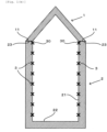
- N in Fig. 1(a) represents the number of horizontal cutting paths 3 necessary until the horizontal cutting path 3 reaches a horizontal cutting path 30 at the final stage, which is a location 23 of the top edge of the bottom interior space-forming region 2 or a location below the location 23 by a shorter distance than a cutting width
- Fig. 1(b) represents a case in which the horizontal cutting path 30 at the final stage corresponding to N of Fig. 1(a) is a location below the top edge 23 by a shorter distance than the cutting width.
- step 1(3) since the command for lamination at the opening of the top edge 23 is set, the step of cutting the opening in the horizontal direction, corresponding to be meaningless and a hindrance to working efficiency is not carried out.
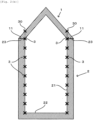
- N in Fig. 2(a) represents the number of the horizontal cutting paths 3 necessary until the horizontal cutting path 3 reaches the location 23 of the top edge in the interior space-forming region 2, or a location below the location by a shorter distance than the cutting width, which is a location that is below the cutting location of the final stage by the cutting width, while Fig. 2(b) represents a case in which the location of the horizontal cutting path 3 corresponding to N of Fig. 2(a) is the location 23 of the top edge.
- step 1(3) above it is possible to carry out cutting for the opening of the top edge 23 in the horizontal direction, since the cutting does not constitute cutting at the final stage by setting the command for terminating cutting along the horizontal cutting path 30 at the final stage which is positioned at upper side of the uppermost cutting path of the basic construction (a) by the cutting width, and corresponds to the uppermost location, and so cutting is carried out along the horizontal cutting path 3 at a second location from the upper side.
- the terminating command since the terminating command is carried out immediately as the subsequent step after completing cutting at the second location from the upper side, the terminating command does not constitute a hindrance against efficient shaping.
- step 1(3) idle rolling is not carried out actually by the terminating command.
- each prescribed location of the cutting blade of the cutting tool in each respective step 1(2) of the basic constructions (a) and (b), it is possible to select any location from the top edge to the bottom edge of the cutting blade, but usually a central location or the bottom edge location will be selected.
- N' in Fig. 3(a) represents the number until the horizontal cutting path 3 created from the bottom edge 11 in the undercut region 1 reaches the horizontal cutting path 30 at the final stage at the location of a highest opening 12 or a location below the location of the highest opening 12 by a shorter distance than cutting width of an undercut cutting tool, as in 1(3) below, while Fig. 3(b) represents a case where the horizontal cutting path 3 corresponding to N' of Fig. 3(a) is the location below the highest opening 12 by a distance shorter than the cutting direction width.
- the CAD/CAM system when cutting has been carried out by the undercut cutting tool along the horizontal cutting path 3 where the side is the highest opening 12, since the cutting corresponds to cutting at the final stage, the CAD/CAM system must issue a command for cutting of the horizontal plane of the highest opening 12 and the cutting must actually be carried out.
- the invention for shaping of the three-dimensional shaped product constituting the top undercut region and the bottom interior space-forming region, it is possible to avoid cutting of the top edge surface in the interior space-forming region and to accomplish efficient cutting of the interior wall section, and therefore the invention has very high practical value.
Landscapes
- Engineering & Computer Science (AREA)
- Materials Engineering (AREA)
- Chemical & Material Sciences (AREA)
- Manufacturing & Machinery (AREA)
- Physics & Mathematics (AREA)
- Optics & Photonics (AREA)
- Mechanical Engineering (AREA)
- General Physics & Mathematics (AREA)
- Automation & Control Theory (AREA)
- Human Computer Interaction (AREA)
- Robotics (AREA)
- Theoretical Computer Science (AREA)
- Geometry (AREA)
- Computational Mathematics (AREA)
- Life Sciences & Earth Sciences (AREA)
- Mathematical Analysis (AREA)
- Mathematical Optimization (AREA)
- Pure & Applied Mathematics (AREA)
- Computer Hardware Design (AREA)
- Evolutionary Computation (AREA)
- General Engineering & Computer Science (AREA)
- Forests & Forestry (AREA)
- Plasma & Fusion (AREA)
- Composite Materials (AREA)
- Powder Metallurgy (AREA)
- Milling Processes (AREA)
Claims (5)
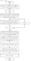
- Procédé de fabrication d'un produit de forme tridimensionnelle basé sur la stratification avec une poudre pendant le déplacement d'une raclette, le frittage de la couche stratifiée par irradiation avec un faisceau laser ou un faisceau d'électrons, et la coupe de la couche frittée avec un outil de coupe (4) mobile, dans lequel une zone de contre-dépouille (1) sur le côté supérieur du produit et une zone en forme de tuyau (2) avec une ouverture sur son bord supérieur et un fond (22) sur le côté inférieur du produit sont jointes par les étapes suivantes :1. un système CAO/FAO définit les étapes suivantes, dans lequel le système CAO/FAO est programmé pour couper automatiquement dans le sens horizontal l'ouverture du bord supérieur de la zone en forme de tuyau (2) lorsqu'une étape de coupe finale a été achevée :(1) création d'une forme de la zone de contre-dépouille (1) qui présente une ouverture correspondant à l'ouverture de la zone en forme de tuyau (2) sur un bord inférieur de la zone de contre-dépouille (1), et création d'une forme de la zone en forme de tuyau (2) ;(2) création d'une trajectoire de coupe (3) avec un sens horizontal pour chaque emplacement des emplacements successifs d'une lame de coupe de l'outil de coupe sur une paroi intérieure (21) de la zone en forme de tuyau (2), dans laquelle un emplacement central ou un emplacement le plus bas de la lame de coupe est sélectionné comme référence pour la trajectoire de coupe (3), et dans laquelle les emplacements sur la paroi intérieure (21) sont disposés dans un ordre régulier le long d'un sens ascendant à partir du fond (22), dans laquelle une largeur entre les emplacements successifs sur la paroi intérieure (21) est définie par la largeur de coupe de la lame de coupe ;(3) lorsque la trajectoire de coupe (3) dans le sens horizontal, créée dans l'ordre régulier à l'étape (2) ci-dessus, a atteint l'emplacement de l'ouverture de la zone en forme de tuyau (2) ou un emplacement en-dessous de l'ouverture de la zone en forme de tuyau (2) sur une distance plus courte que la largeur de coupe, le réglage d'une commande pour une stratification supplémentaire sur le bord supérieur de l'ouverture de la zone en forme de tuyau (2) afin que le système CAO/FAO juge que la coupe à l'ouverture de la zone en forme de tuyau (2) n'est pas l'étape de coupe finale, évitant ainsi une coupe dans le sens horizontal à l'ouverture sur le bord supérieur de la zone en forme de tuyau ;(4) une commande pour joindre le bord inférieur de la zone de contre-dépouille (1) et le bord supérieur de la zone en forme de tuyau (2) afin de déterminer l'emplacement de la stratification et du frittage de la zone de contre-dépouille (1) par rapport à la zone en forme de tuyau (2) ;2. stratification et frittage dans la zone en forme de tuyau (2) sur la base de l'étape 1(1) ci-dessus ;3. coupe de la paroi intérieure (21) le long des trajectoires de coupe (3) dans le sens horizontal, créées par l'étape 1(2) ci-dessus ; et4. stratification et frittage dans la zone de contre-dépouille (1) sur la base des étapes 1(1) et 1(4) ci-dessus.
- Procédé de fabrication d'un produit de forme tridimensionnelle basé sur la stratification avec une poudre pendant le déplacement d'une raclette, le frittage de la couche stratifiée par irradiation avec un faisceau laser ou un faisceau d'électrons, et la coupe de la couche frittée avec un outil de coupe (4) mobile, dans lequel une zone de contre-dépouille (1) sur le côté supérieur du produit et une zone en forme de tuyau (2) avec une ouverture sur son bord supérieur et un fond (22) sur le côté inférieur du produit sont jointes par les étapes suivantes :1. un système CAO/FAO définit les étapes suivantes, dans lequel le système CAO/FAO est programmé pour couper automatiquement dans le sens horizontal l'ouverture du bord supérieur de la zone en forme de tuyau (2) lorsqu'une étape de coupe finale a été achevée :(1) création d'une forme de la zone de contre-dépouille (1) qui présente une ouverture correspondant à l'ouverture de la zone en forme de tuyau (2) sur un bord inférieur de la zone de contre-dépouille (1), et création d'une forme de la zone en forme de tuyau (2) ;(2) création d'une trajectoire de coupe (3) avec un sens horizontal pour chaque emplacement des emplacements successifs d'une lame de coupe de l'outil de coupe sur une paroi intérieure (21) de la zone en forme de tuyau (2), dans laquelle un emplacement central ou un emplacement le plus bas de la lame de coupe est sélectionné comme référence pour la trajectoire de coupe (3), et dans laquelle les emplacements sur la paroi intérieure (21) sont disposés dans un ordre régulier le long d'un sens ascendant à partir du fond (22), dans laquelle une largeur entre les emplacements successifs sur la paroi intérieure (21) est définie par la largeur de coupe de la lame de coupe ;(3) lorsque la trajectoire de coupe (3) dans le sens horizontal, créée dans l'ordre régulier à l'étape (2) ci-dessus, a atteint l'emplacement de l'ouverture de la zone en forme de tuyau (2) ou un emplacement en-dessous de l'ouverture de la zone en forme de tuyau (2) sur une distance plus courte que la largeur de coupe, la création d'une trajectoire de coupe finale dans le sens horizontal à un emplacement qui est au-dessus de la Nième trajectoire de coupe, par la largeur de coupe, où N représente le nombre de trajectoires de coupe dans le sens horizontal créées à l'étape (2) ci-dessus pour atteindre l'emplacement de l'ouverture de la zone en forme de tuyau (2) ou l'emplacement en-dessous de l'ouverture de la zone en forme de tuyau (2), et en réglant une commande pour arrêter l'opération de coupe à l'étape finale de la trajectoire de coupe par l'outil de coupe (4) avant que l'outil de coupe (4) ne commence à couper le long de la trajectoire de coupe de l'étape finale, et en évitant de couper dans le sens horizontal à l'ouverture sur le bord supérieur de la zone en forme de tuyau ;(4) une commande pour joindre le bord inférieur de la zone de contre-dépouille (1) et le bord supérieur de la zone en forme de tuyau (2) afin de déterminer l'emplacement de la stratification et du frittage de la zone de contre-dépouille (1) par rapport à la zone en forme de tuyau (2) ;2. stratification et frittage dans la zone en forme de tuyau (1) sur la base de l'étape 1(1) ci-dessus ;3. coupe de la paroi intérieure (21) le long des trajectoires de coupe (3) dans le sens horizontal, créées par l'étape 1(2) ci-dessus ; et4. stratification et frittage dans la zone de contre-dépouille (1) sur la base des étapes 1(1) et 1(4) ci-dessus.
- Procédé de fabrication d'un produit de forme tridimensionnelle par assemblage de la zone de contre-dépouille (1) ayant un angle de contre-dépouille fixe de la zone de contre-dépouille et de la zone en forme de tuyau (2) selon les revendications 1 ou 2, dans lequel la stratification, le frittage et le découpage sont effectués dans la zone de contre-dépouille selon les étapes suivantes :1. les étapes suivantes sont définies par le système CAO/FAO :(1) réglage de l'emplacement d'une ouverture la plus haute (12) située à un emplacement supérieur qui permet d'insérer un outil de coupe de contre-dépouille le long d'un sens incliné de la zone de contre-dépouille (1), parmi les ouvertures formées dans un ordre régulier le long d'un sens ascendant à partir de l'ouverture au bord inférieur de la zone de contre-dépouille (1) par stratification et frittage.(2) création d'une trajectoire de coupe (3) dans le sens horizontal sur la paroi intérieure de la zone de contre-dépouille (1), dans laquelle un emplacement central ou un emplacement le plus bas de la lame de coupe est sélectionné comme référence pour la trajectoire de coupe (3), à chaque emplacement le long du sens incliné en fonction des angles de contre-dépouille de la paroi intérieure de la zone de contre-dépouille (1), à partir de l'ouverture au bord inférieur de la zone de contre-dépouille (1), dans laquelle une largeur entre les emplacements successifs sur la paroi intérieure de la zone de contre-dépouille (1) est définie par la largeur de coupe de la lame de coupe ;(3) création continue de la trajectoire de coupe (3) dans le sens horizontal à l'étape (2) ci-dessus, jusqu'à ce que l'emplacement de la trajectoire de coupe (3) dans le sens horizontal atteigne l'emplacement de l'ouverture la plus haute (12) défini à l'étape (1) ci-dessus ou un emplacement en dessous de l'emplacement de l'ouverture la plus haute sur une distance plus courte que la largeur de l'outil de coupe en contre-dépouille ;2. stratification et frittage dans la zone allant de l'ouverture au bord inférieur de la zone de contre-dépouille (1) jusqu'à l'ouverture la plus haute ;3. coupe de la paroi intérieure de la zone de contre-dépouille (1) le long des trajectoires de coupe (3) dans le sens horizontal, créées par les étapes 1(2) et 1(3) ci-dessus ; et4. stratification et frittage d'une zone qui est formée dans la partie supérieure de l'ouverture la plus haute.
- Procédé de fabrication d'un produit de forme tridimensionnelle par assemblage de la zone de contre-dépouille (1) et de la zone en forme de tuyau (2) selon la revendication 3, dans lequel le système CAO/FAO définit une commande pour une stratification supplémentaire à l'emplacement de l'ouverture la plus haute (12), lorsque la création de la trajectoire de coupe (3) avec le sens horizontal de l'étape 1(3) ci-dessus a été atteinte.
- Procédé de fabrication d'un produit de forme tridimensionnelle par assemblage de la zone de contre-dépouille (1) et de la zone en forme de tuyau (2) selon l'une quelconque des revendications 1, 2, 3 ou 4, dans lequel, au stade où la stratification et le frittage du fond (22) dans la zone en forme de tuyau (2) sont terminés, une surface latérale supérieure du fond (22) est coupée par rotation de l'outil de coupe (4) équipé d'un disque de coupe (40) à son emplacement le plus bas.
Applications Claiming Priority (1)
| Application Number | Priority Date | Filing Date | Title |
|---|---|---|---|
| JP2019098721A JP6600780B1 (ja) | 2019-05-27 | 2019-05-27 | 上側のアンダーカット領域と下側の内部空間を形成する領域との接合による三次元造形物を製造する方法 |
Publications (2)
| Publication Number | Publication Date |
|---|---|
| EP3745294A1 EP3745294A1 (fr) | 2020-12-02 |
| EP3745294B1 true EP3745294B1 (fr) | 2023-06-14 |
Family
ID=68462279
Family Applications (1)
| Application Number | Title | Priority Date | Filing Date |
|---|---|---|---|
| EP19218391.1A Active EP3745294B1 (fr) | 2019-05-27 | 2019-12-20 | Procédé permettant de produire un produit moulé tridimensionnel en joignant la région de contre-dépouille supérieure et la région inférieure formant l'espace intérieur |
Country Status (7)
| Country | Link |
|---|---|
| US (1) | US20200376756A1 (fr) |
| EP (1) | EP3745294B1 (fr) |
| JP (1) | JP6600780B1 (fr) |
| KR (1) | KR102328946B1 (fr) |
| CN (1) | CN111993667B (fr) |
| CA (1) | CA3066270C (fr) |
| ES (1) | ES2949437T3 (fr) |
Family Cites Families (11)
| Publication number | Priority date | Publication date | Assignee | Title |
|---|---|---|---|---|
| JPS57178217A (en) | 1981-04-28 | 1982-11-02 | Nippon Contact Lens Seizo Kk | Contact lens and its manufacture |
| JP4268311B2 (ja) * | 2000-03-31 | 2009-05-27 | 大日本印刷株式会社 | キャップ一体型ブローチューブ容器 |
| JP2002100750A (ja) | 2000-09-25 | 2002-04-05 | Mitsubishi Materials Silicon Corp | Soi基板及びその製造方法 |
| US6495794B2 (en) | 2001-01-31 | 2002-12-17 | Hanmin Shi | Rapid prototyping method using 3-D laser inner cutting |
| JP3446756B1 (ja) * | 2002-03-26 | 2003-09-16 | 松下電工株式会社 | 粉末焼結部品の表面仕上げ方法 |
| KR200465659Y1 (ko) * | 2010-09-14 | 2013-03-05 | (주)연우 | 링 플립-탑 튜브용기 |
| JP6251447B1 (ja) * | 2017-08-07 | 2017-12-20 | 株式会社松浦機械製作所 | 三次元造形物の内部空間における切削パスの自動作成方法 |
| US20190105844A1 (en) * | 2017-08-07 | 2019-04-11 | Matsuura Machinery Corporation | Method for Automatic Creation of Cutting Paths in Interior Space of Three-Dimensional Shaped Product |
| CN108161000A (zh) * | 2017-11-24 | 2018-06-15 | 北京航空航天大学 | 一种大型复杂金属构件增材及机加工联合制备工艺 |
| JP6458182B1 (ja) * | 2018-03-19 | 2019-01-23 | 株式会社松浦機械製作所 | 三次元造形方法 |
| CN108480821B (zh) * | 2018-03-27 | 2019-10-15 | 福州大学 | 一种圆形截面随形冷却流道的电弧增材制造方法 |
-
2019
- 2019-05-27 JP JP2019098721A patent/JP6600780B1/ja active Active
- 2019-12-12 US US16/711,831 patent/US20200376756A1/en not_active Abandoned
- 2019-12-20 ES ES19218391T patent/ES2949437T3/es active Active
- 2019-12-20 EP EP19218391.1A patent/EP3745294B1/fr active Active
- 2019-12-24 CA CA3066270A patent/CA3066270C/fr active Active
- 2019-12-27 KR KR1020190175953A patent/KR102328946B1/ko active Active
-
2020
- 2020-02-11 CN CN202010087713.1A patent/CN111993667B/zh active Active
Also Published As
| Publication number | Publication date |
|---|---|
| CA3066270A1 (fr) | 2020-03-23 |
| KR20200136302A (ko) | 2020-12-07 |
| ES2949437T3 (es) | 2023-09-28 |
| EP3745294A1 (fr) | 2020-12-02 |
| KR102328946B1 (ko) | 2021-11-22 |
| CN111993667A (zh) | 2020-11-27 |
| JP2020192706A (ja) | 2020-12-03 |
| US20200376756A1 (en) | 2020-12-03 |
| CA3066270C (fr) | 2022-01-25 |
| JP6600780B1 (ja) | 2019-11-06 |
| CN111993667B (zh) | 2022-04-19 |
Similar Documents
| Publication | Publication Date | Title |
|---|---|---|
| US12248293B2 (en) | Computerized tool path generation | |
| CN103608145B (zh) | 使用切割控制规则和变量在一块材料上切割多个工件的方法、系统和计算机程序 | |
| EP2485864B1 (fr) | Règles et variables de commande pour découpage | |
| EP3543011B1 (fr) | Procédé de mise en forme tridimensionnelle | |
| US8403605B2 (en) | Plunge milling method | |
| AU2014313756B2 (en) | Computerized tool path generation | |
| JP5840312B1 (ja) | 三次元造形方法 | |
| EP3243635B1 (fr) | Dispositif de formage en strates en trois dimensions, procédé pour la commande de dispositif de formage en strates en trois dimensions et programme pour la commande du dispositif de formage en strates en trois dimensions | |
| CN105463452A (zh) | 一种激光快速成形件的成形方法 | |
| EP3745294B1 (fr) | Procédé permettant de produire un produit moulé tridimensionnel en joignant la région de contre-dépouille supérieure et la région inférieure formant l'espace intérieur | |
| JP2005154830A (ja) | 粉末焼結部品の表面仕上げ方法 | |
| JP2952369B2 (ja) | ワイヤカット放電加工方法 | |
| CN112756809A (zh) | 一种精密孔件的激光切割方法 |
Legal Events
| Date | Code | Title | Description |
|---|---|---|---|
| PUAI | Public reference made under article 153(3) epc to a published international application that has entered the european phase |
Free format text: ORIGINAL CODE: 0009012 |
|
| STAA | Information on the status of an ep patent application or granted ep patent |
Free format text: STATUS: THE APPLICATION HAS BEEN PUBLISHED |
|
| AK | Designated contracting states |
Kind code of ref document: A1 Designated state(s): AL AT BE BG CH CY CZ DE DK EE ES FI FR GB GR HR HU IE IS IT LI LT LU LV MC MK MT NL NO PL PT RO RS SE SI SK SM TR |
|
| AX | Request for extension of the european patent |
Extension state: BA ME |
|
| STAA | Information on the status of an ep patent application or granted ep patent |
Free format text: STATUS: REQUEST FOR EXAMINATION WAS MADE |
|
| 17P | Request for examination filed |
Effective date: 20210317 |
|
| RBV | Designated contracting states (corrected) |
Designated state(s): AL AT BE BG CH CY CZ DE DK EE ES FI FR GB GR HR HU IE IS IT LI LT LU LV MC MK MT NL NO PL PT RO RS SE SI SK SM TR |
|
| STAA | Information on the status of an ep patent application or granted ep patent |
Free format text: STATUS: EXAMINATION IS IN PROGRESS |
|
| 17Q | First examination report despatched |
Effective date: 20210601 |
|
| GRAP | Despatch of communication of intention to grant a patent |
Free format text: ORIGINAL CODE: EPIDOSNIGR1 |
|
| STAA | Information on the status of an ep patent application or granted ep patent |
Free format text: STATUS: GRANT OF PATENT IS INTENDED |
|
| RIC1 | Information provided on ipc code assigned before grant |
Ipc: G06F 113/10 20200101ALN20230202BHEP Ipc: G06F 30/10 20200101AFI20230202BHEP |
|
| RIC1 | Information provided on ipc code assigned before grant |
Ipc: G06F 113/10 20200101ALN20230207BHEP Ipc: B33Y 40/20 20200101ALI20230207BHEP Ipc: B29C 69/00 20060101ALI20230207BHEP Ipc: B29C 64/393 20170101ALI20230207BHEP Ipc: B29C 64/188 20170101ALI20230207BHEP Ipc: B22F 10/85 20210101ALI20230207BHEP Ipc: B22F 10/66 20210101ALI20230207BHEP Ipc: G06F 30/10 20200101AFI20230207BHEP |
|
| INTG | Intention to grant announced |
Effective date: 20230221 |
|
| GRAS | Grant fee paid |
Free format text: ORIGINAL CODE: EPIDOSNIGR3 |
|
| GRAA | (expected) grant |
Free format text: ORIGINAL CODE: 0009210 |
|
| STAA | Information on the status of an ep patent application or granted ep patent |
Free format text: STATUS: THE PATENT HAS BEEN GRANTED |
|
| AK | Designated contracting states |
Kind code of ref document: B1 Designated state(s): AL AT BE BG CH CY CZ DE DK EE ES FI FR GB GR HR HU IE IS IT LI LT LU LV MC MK MT NL NO PL PT RO RS SE SI SK SM TR |
|
| REG | Reference to a national code |
Ref country code: CH Ref legal event code: EP |
|
| REG | Reference to a national code |
Ref country code: DE Ref legal event code: R096 Ref document number: 602019030961 Country of ref document: DE |
|
| REG | Reference to a national code |
Ref country code: AT Ref legal event code: REF Ref document number: 1579750 Country of ref document: AT Kind code of ref document: T Effective date: 20230715 |
|
| REG | Reference to a national code |
Ref country code: ES Ref legal event code: FG2A Ref document number: 2949437 Country of ref document: ES Kind code of ref document: T3 Effective date: 20230928 |
|
| REG | Reference to a national code |
Ref country code: LT Ref legal event code: MG9D |
|
| REG | Reference to a national code |
Ref country code: NL Ref legal event code: MP Effective date: 20230614 |
|
| PG25 | Lapsed in a contracting state [announced via postgrant information from national office to epo] |
Ref country code: SE Free format text: LAPSE BECAUSE OF FAILURE TO SUBMIT A TRANSLATION OF THE DESCRIPTION OR TO PAY THE FEE WITHIN THE PRESCRIBED TIME-LIMIT Effective date: 20230614 Ref country code: NO Free format text: LAPSE BECAUSE OF FAILURE TO SUBMIT A TRANSLATION OF THE DESCRIPTION OR TO PAY THE FEE WITHIN THE PRESCRIBED TIME-LIMIT Effective date: 20230914 |
|
| REG | Reference to a national code |
Ref country code: AT Ref legal event code: MK05 Ref document number: 1579750 Country of ref document: AT Kind code of ref document: T Effective date: 20230614 |
|
| PG25 | Lapsed in a contracting state [announced via postgrant information from national office to epo] |
Ref country code: RS Free format text: LAPSE BECAUSE OF FAILURE TO SUBMIT A TRANSLATION OF THE DESCRIPTION OR TO PAY THE FEE WITHIN THE PRESCRIBED TIME-LIMIT Effective date: 20230614 Ref country code: NL Free format text: LAPSE BECAUSE OF FAILURE TO SUBMIT A TRANSLATION OF THE DESCRIPTION OR TO PAY THE FEE WITHIN THE PRESCRIBED TIME-LIMIT Effective date: 20230614 Ref country code: LV Free format text: LAPSE BECAUSE OF FAILURE TO SUBMIT A TRANSLATION OF THE DESCRIPTION OR TO PAY THE FEE WITHIN THE PRESCRIBED TIME-LIMIT Effective date: 20230614 Ref country code: LT Free format text: LAPSE BECAUSE OF FAILURE TO SUBMIT A TRANSLATION OF THE DESCRIPTION OR TO PAY THE FEE WITHIN THE PRESCRIBED TIME-LIMIT Effective date: 20230614 Ref country code: HR Free format text: LAPSE BECAUSE OF FAILURE TO SUBMIT A TRANSLATION OF THE DESCRIPTION OR TO PAY THE FEE WITHIN THE PRESCRIBED TIME-LIMIT Effective date: 20230614 Ref country code: GR Free format text: LAPSE BECAUSE OF FAILURE TO SUBMIT A TRANSLATION OF THE DESCRIPTION OR TO PAY THE FEE WITHIN THE PRESCRIBED TIME-LIMIT Effective date: 20230915 |
|
| PG25 | Lapsed in a contracting state [announced via postgrant information from national office to epo] |
Ref country code: FI Free format text: LAPSE BECAUSE OF FAILURE TO SUBMIT A TRANSLATION OF THE DESCRIPTION OR TO PAY THE FEE WITHIN THE PRESCRIBED TIME-LIMIT Effective date: 20230614 |
|
| PG25 | Lapsed in a contracting state [announced via postgrant information from national office to epo] |
Ref country code: SK Free format text: LAPSE BECAUSE OF FAILURE TO SUBMIT A TRANSLATION OF THE DESCRIPTION OR TO PAY THE FEE WITHIN THE PRESCRIBED TIME-LIMIT Effective date: 20230614 |
|
| PG25 | Lapsed in a contracting state [announced via postgrant information from national office to epo] |
Ref country code: IS Free format text: LAPSE BECAUSE OF FAILURE TO SUBMIT A TRANSLATION OF THE DESCRIPTION OR TO PAY THE FEE WITHIN THE PRESCRIBED TIME-LIMIT Effective date: 20231014 |
|
| PG25 | Lapsed in a contracting state [announced via postgrant information from national office to epo] |
Ref country code: SM Free format text: LAPSE BECAUSE OF FAILURE TO SUBMIT A TRANSLATION OF THE DESCRIPTION OR TO PAY THE FEE WITHIN THE PRESCRIBED TIME-LIMIT Effective date: 20230614 Ref country code: SK Free format text: LAPSE BECAUSE OF FAILURE TO SUBMIT A TRANSLATION OF THE DESCRIPTION OR TO PAY THE FEE WITHIN THE PRESCRIBED TIME-LIMIT Effective date: 20230614 Ref country code: RO Free format text: LAPSE BECAUSE OF FAILURE TO SUBMIT A TRANSLATION OF THE DESCRIPTION OR TO PAY THE FEE WITHIN THE PRESCRIBED TIME-LIMIT Effective date: 20230614 Ref country code: PT Free format text: LAPSE BECAUSE OF FAILURE TO SUBMIT A TRANSLATION OF THE DESCRIPTION OR TO PAY THE FEE WITHIN THE PRESCRIBED TIME-LIMIT Effective date: 20231016 Ref country code: IS Free format text: LAPSE BECAUSE OF FAILURE TO SUBMIT A TRANSLATION OF THE DESCRIPTION OR TO PAY THE FEE WITHIN THE PRESCRIBED TIME-LIMIT Effective date: 20231014 Ref country code: EE Free format text: LAPSE BECAUSE OF FAILURE TO SUBMIT A TRANSLATION OF THE DESCRIPTION OR TO PAY THE FEE WITHIN THE PRESCRIBED TIME-LIMIT Effective date: 20230614 Ref country code: CZ Free format text: LAPSE BECAUSE OF FAILURE TO SUBMIT A TRANSLATION OF THE DESCRIPTION OR TO PAY THE FEE WITHIN THE PRESCRIBED TIME-LIMIT Effective date: 20230614 Ref country code: AT Free format text: LAPSE BECAUSE OF FAILURE TO SUBMIT A TRANSLATION OF THE DESCRIPTION OR TO PAY THE FEE WITHIN THE PRESCRIBED TIME-LIMIT Effective date: 20230614 |
|
| PG25 | Lapsed in a contracting state [announced via postgrant information from national office to epo] |
Ref country code: PL Free format text: LAPSE BECAUSE OF FAILURE TO SUBMIT A TRANSLATION OF THE DESCRIPTION OR TO PAY THE FEE WITHIN THE PRESCRIBED TIME-LIMIT Effective date: 20230614 |
|
| REG | Reference to a national code |
Ref country code: DE Ref legal event code: R097 Ref document number: 602019030961 Country of ref document: DE |
|
| PLBE | No opposition filed within time limit |
Free format text: ORIGINAL CODE: 0009261 |
|
| STAA | Information on the status of an ep patent application or granted ep patent |
Free format text: STATUS: NO OPPOSITION FILED WITHIN TIME LIMIT |
|
| PG25 | Lapsed in a contracting state [announced via postgrant information from national office to epo] |
Ref country code: DK Free format text: LAPSE BECAUSE OF FAILURE TO SUBMIT A TRANSLATION OF THE DESCRIPTION OR TO PAY THE FEE WITHIN THE PRESCRIBED TIME-LIMIT Effective date: 20230614 |
|
| PG25 | Lapsed in a contracting state [announced via postgrant information from national office to epo] |
Ref country code: SI Free format text: LAPSE BECAUSE OF FAILURE TO SUBMIT A TRANSLATION OF THE DESCRIPTION OR TO PAY THE FEE WITHIN THE PRESCRIBED TIME-LIMIT Effective date: 20230614 |
|
| 26N | No opposition filed |
Effective date: 20240315 |
|
| PG25 | Lapsed in a contracting state [announced via postgrant information from national office to epo] |
Ref country code: SI Free format text: LAPSE BECAUSE OF FAILURE TO SUBMIT A TRANSLATION OF THE DESCRIPTION OR TO PAY THE FEE WITHIN THE PRESCRIBED TIME-LIMIT Effective date: 20230614 |
|
| PG25 | Lapsed in a contracting state [announced via postgrant information from national office to epo] |
Ref country code: LU Free format text: LAPSE BECAUSE OF NON-PAYMENT OF DUE FEES Effective date: 20231220 |
|
| PG25 | Lapsed in a contracting state [announced via postgrant information from national office to epo] |
Ref country code: MC Free format text: LAPSE BECAUSE OF FAILURE TO SUBMIT A TRANSLATION OF THE DESCRIPTION OR TO PAY THE FEE WITHIN THE PRESCRIBED TIME-LIMIT Effective date: 20230614 |
|
| REG | Reference to a national code |
Ref country code: BE Ref legal event code: MM Effective date: 20231231 |
|
| PG25 | Lapsed in a contracting state [announced via postgrant information from national office to epo] |
Ref country code: MC Free format text: LAPSE BECAUSE OF FAILURE TO SUBMIT A TRANSLATION OF THE DESCRIPTION OR TO PAY THE FEE WITHIN THE PRESCRIBED TIME-LIMIT Effective date: 20230614 Ref country code: LU Free format text: LAPSE BECAUSE OF NON-PAYMENT OF DUE FEES Effective date: 20231220 |
|
| REG | Reference to a national code |
Ref country code: IE Ref legal event code: MM4A |
|
| PG25 | Lapsed in a contracting state [announced via postgrant information from national office to epo] |
Ref country code: IE Free format text: LAPSE BECAUSE OF NON-PAYMENT OF DUE FEES Effective date: 20231220 |
|
| PG25 | Lapsed in a contracting state [announced via postgrant information from national office to epo] |
Ref country code: BE Free format text: LAPSE BECAUSE OF NON-PAYMENT OF DUE FEES Effective date: 20231231 |
|
| PG25 | Lapsed in a contracting state [announced via postgrant information from national office to epo] |
Ref country code: IE Free format text: LAPSE BECAUSE OF NON-PAYMENT OF DUE FEES Effective date: 20231220 Ref country code: BE Free format text: LAPSE BECAUSE OF NON-PAYMENT OF DUE FEES Effective date: 20231231 |
|
| PG25 | Lapsed in a contracting state [announced via postgrant information from national office to epo] |
Ref country code: BG Free format text: LAPSE BECAUSE OF FAILURE TO SUBMIT A TRANSLATION OF THE DESCRIPTION OR TO PAY THE FEE WITHIN THE PRESCRIBED TIME-LIMIT Effective date: 20230614 |
|
| PG25 | Lapsed in a contracting state [announced via postgrant information from national office to epo] |
Ref country code: BG Free format text: LAPSE BECAUSE OF FAILURE TO SUBMIT A TRANSLATION OF THE DESCRIPTION OR TO PAY THE FEE WITHIN THE PRESCRIBED TIME-LIMIT Effective date: 20230614 |
|
| PGFP | Annual fee paid to national office [announced via postgrant information from national office to epo] |
Ref country code: CH Payment date: 20250101 Year of fee payment: 6 |
|
| PG25 | Lapsed in a contracting state [announced via postgrant information from national office to epo] |
Ref country code: CY Free format text: LAPSE BECAUSE OF FAILURE TO SUBMIT A TRANSLATION OF THE DESCRIPTION OR TO PAY THE FEE WITHIN THE PRESCRIBED TIME-LIMIT; INVALID AB INITIO Effective date: 20191220 |
|
| PG25 | Lapsed in a contracting state [announced via postgrant information from national office to epo] |
Ref country code: HU Free format text: LAPSE BECAUSE OF FAILURE TO SUBMIT A TRANSLATION OF THE DESCRIPTION OR TO PAY THE FEE WITHIN THE PRESCRIBED TIME-LIMIT; INVALID AB INITIO Effective date: 20191220 |
|
| PG25 | Lapsed in a contracting state [announced via postgrant information from national office to epo] |
Ref country code: TR Free format text: LAPSE BECAUSE OF FAILURE TO SUBMIT A TRANSLATION OF THE DESCRIPTION OR TO PAY THE FEE WITHIN THE PRESCRIBED TIME-LIMIT Effective date: 20230614 |
|
| PGFP | Annual fee paid to national office [announced via postgrant information from national office to epo] |
Ref country code: DE Payment date: 20251202 Year of fee payment: 7 |
|
| PGFP | Annual fee paid to national office [announced via postgrant information from national office to epo] |
Ref country code: GB Payment date: 20251229 Year of fee payment: 7 |
|
| PGFP | Annual fee paid to national office [announced via postgrant information from national office to epo] |
Ref country code: FR Payment date: 20251223 Year of fee payment: 7 |
|
| PGFP | Annual fee paid to national office [announced via postgrant information from national office to epo] |
Ref country code: ES Payment date: 20260102 Year of fee payment: 7 |
|
| PGFP | Annual fee paid to national office [announced via postgrant information from national office to epo] |
Ref country code: IT Payment date: 20251229 Year of fee payment: 7 |