EP3745378A1 - Procédé, dispositif et système d'évaluation de sécurité de conduite automatique - Google Patents
Procédé, dispositif et système d'évaluation de sécurité de conduite automatique Download PDFInfo
- Publication number
- EP3745378A1 EP3745378A1 EP19768393.1A EP19768393A EP3745378A1 EP 3745378 A1 EP3745378 A1 EP 3745378A1 EP 19768393 A EP19768393 A EP 19768393A EP 3745378 A1 EP3745378 A1 EP 3745378A1
- Authority
- EP
- European Patent Office
- Prior art keywords
- vehicle
- risk
- driving mode
- self
- moment
- Prior art date
- Legal status (The legal status is an assumption and is not a legal conclusion. Google has not performed a legal analysis and makes no representation as to the accuracy of the status listed.)
- Granted
Links
Images









Classifications
-
- B—PERFORMING OPERATIONS; TRANSPORTING
- B60—VEHICLES IN GENERAL
- B60W—CONJOINT CONTROL OF VEHICLE SUB-UNITS OF DIFFERENT TYPE OR DIFFERENT FUNCTION; CONTROL SYSTEMS SPECIALLY ADAPTED FOR HYBRID VEHICLES; ROAD VEHICLE DRIVE CONTROL SYSTEMS FOR PURPOSES NOT RELATED TO THE CONTROL OF A PARTICULAR SUB-UNIT
- B60W50/00—Details of control systems for road vehicle drive control not related to the control of a particular sub-unit, e.g. process diagnostic or vehicle driver interfaces
- B60W50/04—Monitoring the functioning of the control system
- B60W50/045—Monitoring control system parameters
-
- B—PERFORMING OPERATIONS; TRANSPORTING
- B60—VEHICLES IN GENERAL
- B60W—CONJOINT CONTROL OF VEHICLE SUB-UNITS OF DIFFERENT TYPE OR DIFFERENT FUNCTION; CONTROL SYSTEMS SPECIALLY ADAPTED FOR HYBRID VEHICLES; ROAD VEHICLE DRIVE CONTROL SYSTEMS FOR PURPOSES NOT RELATED TO THE CONTROL OF A PARTICULAR SUB-UNIT
- B60W30/00—Purposes of road vehicle drive control systems not related to the control of a particular sub-unit, e.g. of systems using conjoint control of vehicle sub-units
- B60W30/08—Active safety systems predicting or avoiding probable or impending collision or attempting to minimise its consequences
-
- B—PERFORMING OPERATIONS; TRANSPORTING
- B60—VEHICLES IN GENERAL
- B60W—CONJOINT CONTROL OF VEHICLE SUB-UNITS OF DIFFERENT TYPE OR DIFFERENT FUNCTION; CONTROL SYSTEMS SPECIALLY ADAPTED FOR HYBRID VEHICLES; ROAD VEHICLE DRIVE CONTROL SYSTEMS FOR PURPOSES NOT RELATED TO THE CONTROL OF A PARTICULAR SUB-UNIT
- B60W30/00—Purposes of road vehicle drive control systems not related to the control of a particular sub-unit, e.g. of systems using conjoint control of vehicle sub-units
- B60W30/08—Active safety systems predicting or avoiding probable or impending collision or attempting to minimise its consequences
- B60W30/095—Predicting travel path or likelihood of collision
-
- B—PERFORMING OPERATIONS; TRANSPORTING
- B60—VEHICLES IN GENERAL
- B60W—CONJOINT CONTROL OF VEHICLE SUB-UNITS OF DIFFERENT TYPE OR DIFFERENT FUNCTION; CONTROL SYSTEMS SPECIALLY ADAPTED FOR HYBRID VEHICLES; ROAD VEHICLE DRIVE CONTROL SYSTEMS FOR PURPOSES NOT RELATED TO THE CONTROL OF A PARTICULAR SUB-UNIT
- B60W30/00—Purposes of road vehicle drive control systems not related to the control of a particular sub-unit, e.g. of systems using conjoint control of vehicle sub-units
- B60W30/18—Propelling the vehicle
-
- B—PERFORMING OPERATIONS; TRANSPORTING
- B60—VEHICLES IN GENERAL
- B60W—CONJOINT CONTROL OF VEHICLE SUB-UNITS OF DIFFERENT TYPE OR DIFFERENT FUNCTION; CONTROL SYSTEMS SPECIALLY ADAPTED FOR HYBRID VEHICLES; ROAD VEHICLE DRIVE CONTROL SYSTEMS FOR PURPOSES NOT RELATED TO THE CONTROL OF A PARTICULAR SUB-UNIT
- B60W30/00—Purposes of road vehicle drive control systems not related to the control of a particular sub-unit, e.g. of systems using conjoint control of vehicle sub-units
- B60W30/18—Propelling the vehicle
- B60W30/18009—Propelling the vehicle related to particular drive situations
-
- B—PERFORMING OPERATIONS; TRANSPORTING
- B60—VEHICLES IN GENERAL
- B60W—CONJOINT CONTROL OF VEHICLE SUB-UNITS OF DIFFERENT TYPE OR DIFFERENT FUNCTION; CONTROL SYSTEMS SPECIALLY ADAPTED FOR HYBRID VEHICLES; ROAD VEHICLE DRIVE CONTROL SYSTEMS FOR PURPOSES NOT RELATED TO THE CONTROL OF A PARTICULAR SUB-UNIT
- B60W30/00—Purposes of road vehicle drive control systems not related to the control of a particular sub-unit, e.g. of systems using conjoint control of vehicle sub-units
- B60W30/18—Propelling the vehicle
- B60W30/18009—Propelling the vehicle related to particular drive situations
- B60W30/18145—Cornering
-
- B—PERFORMING OPERATIONS; TRANSPORTING
- B60—VEHICLES IN GENERAL
- B60W—CONJOINT CONTROL OF VEHICLE SUB-UNITS OF DIFFERENT TYPE OR DIFFERENT FUNCTION; CONTROL SYSTEMS SPECIALLY ADAPTED FOR HYBRID VEHICLES; ROAD VEHICLE DRIVE CONTROL SYSTEMS FOR PURPOSES NOT RELATED TO THE CONTROL OF A PARTICULAR SUB-UNIT
- B60W30/00—Purposes of road vehicle drive control systems not related to the control of a particular sub-unit, e.g. of systems using conjoint control of vehicle sub-units
- B60W30/18—Propelling the vehicle
- B60W30/18009—Propelling the vehicle related to particular drive situations
- B60W30/18159—Traversing an intersection
-
- B—PERFORMING OPERATIONS; TRANSPORTING
- B60—VEHICLES IN GENERAL
- B60W—CONJOINT CONTROL OF VEHICLE SUB-UNITS OF DIFFERENT TYPE OR DIFFERENT FUNCTION; CONTROL SYSTEMS SPECIALLY ADAPTED FOR HYBRID VEHICLES; ROAD VEHICLE DRIVE CONTROL SYSTEMS FOR PURPOSES NOT RELATED TO THE CONTROL OF A PARTICULAR SUB-UNIT
- B60W30/00—Purposes of road vehicle drive control systems not related to the control of a particular sub-unit, e.g. of systems using conjoint control of vehicle sub-units
- B60W30/18—Propelling the vehicle
- B60W30/18009—Propelling the vehicle related to particular drive situations
- B60W30/18163—Lane change; Overtaking manoeuvres
-
- B—PERFORMING OPERATIONS; TRANSPORTING
- B60—VEHICLES IN GENERAL
- B60W—CONJOINT CONTROL OF VEHICLE SUB-UNITS OF DIFFERENT TYPE OR DIFFERENT FUNCTION; CONTROL SYSTEMS SPECIALLY ADAPTED FOR HYBRID VEHICLES; ROAD VEHICLE DRIVE CONTROL SYSTEMS FOR PURPOSES NOT RELATED TO THE CONTROL OF A PARTICULAR SUB-UNIT
- B60W30/00—Purposes of road vehicle drive control systems not related to the control of a particular sub-unit, e.g. of systems using conjoint control of vehicle sub-units
- B60W30/18—Propelling the vehicle
- B60W30/182—Selecting between different operative modes, e.g. comfort and performance modes
-
- B—PERFORMING OPERATIONS; TRANSPORTING
- B60—VEHICLES IN GENERAL
- B60W—CONJOINT CONTROL OF VEHICLE SUB-UNITS OF DIFFERENT TYPE OR DIFFERENT FUNCTION; CONTROL SYSTEMS SPECIALLY ADAPTED FOR HYBRID VEHICLES; ROAD VEHICLE DRIVE CONTROL SYSTEMS FOR PURPOSES NOT RELATED TO THE CONTROL OF A PARTICULAR SUB-UNIT
- B60W50/00—Details of control systems for road vehicle drive control not related to the control of a particular sub-unit, e.g. process diagnostic or vehicle driver interfaces
- B60W50/08—Interaction between the driver and the control system
- B60W50/082—Selecting or switching between different modes of propelling
-
- B—PERFORMING OPERATIONS; TRANSPORTING
- B60—VEHICLES IN GENERAL
- B60W—CONJOINT CONTROL OF VEHICLE SUB-UNITS OF DIFFERENT TYPE OR DIFFERENT FUNCTION; CONTROL SYSTEMS SPECIALLY ADAPTED FOR HYBRID VEHICLES; ROAD VEHICLE DRIVE CONTROL SYSTEMS FOR PURPOSES NOT RELATED TO THE CONTROL OF A PARTICULAR SUB-UNIT
- B60W50/00—Details of control systems for road vehicle drive control not related to the control of a particular sub-unit, e.g. process diagnostic or vehicle driver interfaces
- B60W50/08—Interaction between the driver and the control system
- B60W50/10—Interpretation of driver requests or demands
-
- B—PERFORMING OPERATIONS; TRANSPORTING
- B60—VEHICLES IN GENERAL
- B60W—CONJOINT CONTROL OF VEHICLE SUB-UNITS OF DIFFERENT TYPE OR DIFFERENT FUNCTION; CONTROL SYSTEMS SPECIALLY ADAPTED FOR HYBRID VEHICLES; ROAD VEHICLE DRIVE CONTROL SYSTEMS FOR PURPOSES NOT RELATED TO THE CONTROL OF A PARTICULAR SUB-UNIT
- B60W60/00—Drive control systems specially adapted for autonomous road vehicles
- B60W60/001—Planning or execution of driving tasks
- B60W60/0011—Planning or execution of driving tasks involving control alternatives for a single driving scenario, e.g. planning several paths to avoid obstacles
-
- B—PERFORMING OPERATIONS; TRANSPORTING
- B60—VEHICLES IN GENERAL
- B60W—CONJOINT CONTROL OF VEHICLE SUB-UNITS OF DIFFERENT TYPE OR DIFFERENT FUNCTION; CONTROL SYSTEMS SPECIALLY ADAPTED FOR HYBRID VEHICLES; ROAD VEHICLE DRIVE CONTROL SYSTEMS FOR PURPOSES NOT RELATED TO THE CONTROL OF A PARTICULAR SUB-UNIT
- B60W60/00—Drive control systems specially adapted for autonomous road vehicles
- B60W60/005—Handover processes
- B60W60/0059—Estimation of the risk associated with autonomous or manual driving, e.g. situation too complex, sensor failure or driver incapacity
-
- G—PHYSICS
- G06—COMPUTING OR CALCULATING; COUNTING
- G06F—ELECTRIC DIGITAL DATA PROCESSING
- G06F11/00—Error detection; Error correction; Monitoring
- G06F11/30—Monitoring
- G06F11/3003—Monitoring arrangements specially adapted to the computing system or computing system component being monitored
- G06F11/3013—Monitoring arrangements specially adapted to the computing system or computing system component being monitored where the computing system is an embedded system, i.e. a combination of hardware and software dedicated to perform a certain function in mobile devices, printers, automotive or aircraft systems
-
- G—PHYSICS
- G06—COMPUTING OR CALCULATING; COUNTING
- G06Q—INFORMATION AND COMMUNICATION TECHNOLOGY [ICT] SPECIALLY ADAPTED FOR ADMINISTRATIVE, COMMERCIAL, FINANCIAL, MANAGERIAL OR SUPERVISORY PURPOSES; SYSTEMS OR METHODS SPECIALLY ADAPTED FOR ADMINISTRATIVE, COMMERCIAL, FINANCIAL, MANAGERIAL OR SUPERVISORY PURPOSES, NOT OTHERWISE PROVIDED FOR
- G06Q10/00—Administration; Management
- G06Q10/04—Forecasting or optimisation specially adapted for administrative or management purposes, e.g. linear programming or "cutting stock problem"
-
- G—PHYSICS
- G06—COMPUTING OR CALCULATING; COUNTING
- G06Q—INFORMATION AND COMMUNICATION TECHNOLOGY [ICT] SPECIALLY ADAPTED FOR ADMINISTRATIVE, COMMERCIAL, FINANCIAL, MANAGERIAL OR SUPERVISORY PURPOSES; SYSTEMS OR METHODS SPECIALLY ADAPTED FOR ADMINISTRATIVE, COMMERCIAL, FINANCIAL, MANAGERIAL OR SUPERVISORY PURPOSES, NOT OTHERWISE PROVIDED FOR
- G06Q10/00—Administration; Management
- G06Q10/04—Forecasting or optimisation specially adapted for administrative or management purposes, e.g. linear programming or "cutting stock problem"
- G06Q10/047—Optimisation of routes or paths, e.g. travelling salesman problem
-
- G—PHYSICS
- G06—COMPUTING OR CALCULATING; COUNTING
- G06Q—INFORMATION AND COMMUNICATION TECHNOLOGY [ICT] SPECIALLY ADAPTED FOR ADMINISTRATIVE, COMMERCIAL, FINANCIAL, MANAGERIAL OR SUPERVISORY PURPOSES; SYSTEMS OR METHODS SPECIALLY ADAPTED FOR ADMINISTRATIVE, COMMERCIAL, FINANCIAL, MANAGERIAL OR SUPERVISORY PURPOSES, NOT OTHERWISE PROVIDED FOR
- G06Q10/00—Administration; Management
- G06Q10/06—Resources, workflows, human or project management; Enterprise or organisation planning; Enterprise or organisation modelling
-
- G—PHYSICS
- G06—COMPUTING OR CALCULATING; COUNTING
- G06Q—INFORMATION AND COMMUNICATION TECHNOLOGY [ICT] SPECIALLY ADAPTED FOR ADMINISTRATIVE, COMMERCIAL, FINANCIAL, MANAGERIAL OR SUPERVISORY PURPOSES; SYSTEMS OR METHODS SPECIALLY ADAPTED FOR ADMINISTRATIVE, COMMERCIAL, FINANCIAL, MANAGERIAL OR SUPERVISORY PURPOSES, NOT OTHERWISE PROVIDED FOR
- G06Q10/00—Administration; Management
- G06Q10/06—Resources, workflows, human or project management; Enterprise or organisation planning; Enterprise or organisation modelling
- G06Q10/063—Operations research, analysis or management
- G06Q10/0635—Risk analysis of enterprise or organisation activities
-
- G—PHYSICS
- G06—COMPUTING OR CALCULATING; COUNTING
- G06Q—INFORMATION AND COMMUNICATION TECHNOLOGY [ICT] SPECIALLY ADAPTED FOR ADMINISTRATIVE, COMMERCIAL, FINANCIAL, MANAGERIAL OR SUPERVISORY PURPOSES; SYSTEMS OR METHODS SPECIALLY ADAPTED FOR ADMINISTRATIVE, COMMERCIAL, FINANCIAL, MANAGERIAL OR SUPERVISORY PURPOSES, NOT OTHERWISE PROVIDED FOR
- G06Q50/00—Information and communication technology [ICT] specially adapted for implementation of business processes of specific business sectors, e.g. utilities or tourism
- G06Q50/10—Services
- G06Q50/26—Government or public services
-
- G—PHYSICS
- G06—COMPUTING OR CALCULATING; COUNTING
- G06Q—INFORMATION AND COMMUNICATION TECHNOLOGY [ICT] SPECIALLY ADAPTED FOR ADMINISTRATIVE, COMMERCIAL, FINANCIAL, MANAGERIAL OR SUPERVISORY PURPOSES; SYSTEMS OR METHODS SPECIALLY ADAPTED FOR ADMINISTRATIVE, COMMERCIAL, FINANCIAL, MANAGERIAL OR SUPERVISORY PURPOSES, NOT OTHERWISE PROVIDED FOR
- G06Q50/00—Information and communication technology [ICT] specially adapted for implementation of business processes of specific business sectors, e.g. utilities or tourism
- G06Q50/10—Services
- G06Q50/26—Government or public services
- G06Q50/265—Personal security, identity or safety
-
- G—PHYSICS
- G06—COMPUTING OR CALCULATING; COUNTING
- G06Q—INFORMATION AND COMMUNICATION TECHNOLOGY [ICT] SPECIALLY ADAPTED FOR ADMINISTRATIVE, COMMERCIAL, FINANCIAL, MANAGERIAL OR SUPERVISORY PURPOSES; SYSTEMS OR METHODS SPECIALLY ADAPTED FOR ADMINISTRATIVE, COMMERCIAL, FINANCIAL, MANAGERIAL OR SUPERVISORY PURPOSES, NOT OTHERWISE PROVIDED FOR
- G06Q50/00—Information and communication technology [ICT] specially adapted for implementation of business processes of specific business sectors, e.g. utilities or tourism
- G06Q50/40—Business processes related to the transportation industry
-
- G—PHYSICS
- G08—SIGNALLING
- G08G—TRAFFIC CONTROL SYSTEMS
- G08G1/00—Traffic control systems for road vehicles
- G08G1/16—Anti-collision systems
-
- G—PHYSICS
- G08—SIGNALLING
- G08G—TRAFFIC CONTROL SYSTEMS
- G08G1/00—Traffic control systems for road vehicles
- G08G1/16—Anti-collision systems
- G08G1/166—Anti-collision systems for active traffic, e.g. moving vehicles, pedestrians, bikes
-
- B—PERFORMING OPERATIONS; TRANSPORTING
- B60—VEHICLES IN GENERAL
- B60W—CONJOINT CONTROL OF VEHICLE SUB-UNITS OF DIFFERENT TYPE OR DIFFERENT FUNCTION; CONTROL SYSTEMS SPECIALLY ADAPTED FOR HYBRID VEHICLES; ROAD VEHICLE DRIVE CONTROL SYSTEMS FOR PURPOSES NOT RELATED TO THE CONTROL OF A PARTICULAR SUB-UNIT
- B60W2520/00—Input parameters relating to overall vehicle dynamics
- B60W2520/10—Longitudinal speed
-
- B—PERFORMING OPERATIONS; TRANSPORTING
- B60—VEHICLES IN GENERAL
- B60W—CONJOINT CONTROL OF VEHICLE SUB-UNITS OF DIFFERENT TYPE OR DIFFERENT FUNCTION; CONTROL SYSTEMS SPECIALLY ADAPTED FOR HYBRID VEHICLES; ROAD VEHICLE DRIVE CONTROL SYSTEMS FOR PURPOSES NOT RELATED TO THE CONTROL OF A PARTICULAR SUB-UNIT
- B60W2520/00—Input parameters relating to overall vehicle dynamics
- B60W2520/10—Longitudinal speed
- B60W2520/105—Longitudinal acceleration
-
- B—PERFORMING OPERATIONS; TRANSPORTING
- B60—VEHICLES IN GENERAL
- B60W—CONJOINT CONTROL OF VEHICLE SUB-UNITS OF DIFFERENT TYPE OR DIFFERENT FUNCTION; CONTROL SYSTEMS SPECIALLY ADAPTED FOR HYBRID VEHICLES; ROAD VEHICLE DRIVE CONTROL SYSTEMS FOR PURPOSES NOT RELATED TO THE CONTROL OF A PARTICULAR SUB-UNIT
- B60W2520/00—Input parameters relating to overall vehicle dynamics
- B60W2520/12—Lateral speed
-
- B—PERFORMING OPERATIONS; TRANSPORTING
- B60—VEHICLES IN GENERAL
- B60W—CONJOINT CONTROL OF VEHICLE SUB-UNITS OF DIFFERENT TYPE OR DIFFERENT FUNCTION; CONTROL SYSTEMS SPECIALLY ADAPTED FOR HYBRID VEHICLES; ROAD VEHICLE DRIVE CONTROL SYSTEMS FOR PURPOSES NOT RELATED TO THE CONTROL OF A PARTICULAR SUB-UNIT
- B60W2520/00—Input parameters relating to overall vehicle dynamics
- B60W2520/12—Lateral speed
- B60W2520/125—Lateral acceleration
-
- B—PERFORMING OPERATIONS; TRANSPORTING
- B60—VEHICLES IN GENERAL
- B60W—CONJOINT CONTROL OF VEHICLE SUB-UNITS OF DIFFERENT TYPE OR DIFFERENT FUNCTION; CONTROL SYSTEMS SPECIALLY ADAPTED FOR HYBRID VEHICLES; ROAD VEHICLE DRIVE CONTROL SYSTEMS FOR PURPOSES NOT RELATED TO THE CONTROL OF A PARTICULAR SUB-UNIT
- B60W2552/00—Input parameters relating to infrastructure
- B60W2552/05—Type of road, e.g. motorways, local streets, paved or unpaved roads
-
- B—PERFORMING OPERATIONS; TRANSPORTING
- B60—VEHICLES IN GENERAL
- B60W—CONJOINT CONTROL OF VEHICLE SUB-UNITS OF DIFFERENT TYPE OR DIFFERENT FUNCTION; CONTROL SYSTEMS SPECIALLY ADAPTED FOR HYBRID VEHICLES; ROAD VEHICLE DRIVE CONTROL SYSTEMS FOR PURPOSES NOT RELATED TO THE CONTROL OF A PARTICULAR SUB-UNIT
- B60W2552/00—Input parameters relating to infrastructure
- B60W2552/30—Road curve radius
-
- B—PERFORMING OPERATIONS; TRANSPORTING
- B60—VEHICLES IN GENERAL
- B60W—CONJOINT CONTROL OF VEHICLE SUB-UNITS OF DIFFERENT TYPE OR DIFFERENT FUNCTION; CONTROL SYSTEMS SPECIALLY ADAPTED FOR HYBRID VEHICLES; ROAD VEHICLE DRIVE CONTROL SYSTEMS FOR PURPOSES NOT RELATED TO THE CONTROL OF A PARTICULAR SUB-UNIT
- B60W2554/00—Input parameters relating to objects
- B60W2554/40—Dynamic objects, e.g. animals, windblown objects
-
- B—PERFORMING OPERATIONS; TRANSPORTING
- B60—VEHICLES IN GENERAL
- B60W—CONJOINT CONTROL OF VEHICLE SUB-UNITS OF DIFFERENT TYPE OR DIFFERENT FUNCTION; CONTROL SYSTEMS SPECIALLY ADAPTED FOR HYBRID VEHICLES; ROAD VEHICLE DRIVE CONTROL SYSTEMS FOR PURPOSES NOT RELATED TO THE CONTROL OF A PARTICULAR SUB-UNIT
- B60W2554/00—Input parameters relating to objects
- B60W2554/40—Dynamic objects, e.g. animals, windblown objects
- B60W2554/402—Type
-
- B—PERFORMING OPERATIONS; TRANSPORTING
- B60—VEHICLES IN GENERAL
- B60W—CONJOINT CONTROL OF VEHICLE SUB-UNITS OF DIFFERENT TYPE OR DIFFERENT FUNCTION; CONTROL SYSTEMS SPECIALLY ADAPTED FOR HYBRID VEHICLES; ROAD VEHICLE DRIVE CONTROL SYSTEMS FOR PURPOSES NOT RELATED TO THE CONTROL OF A PARTICULAR SUB-UNIT
- B60W2554/00—Input parameters relating to objects
- B60W2554/80—Spatial relation or speed relative to objects
-
- B—PERFORMING OPERATIONS; TRANSPORTING
- B60—VEHICLES IN GENERAL
- B60W—CONJOINT CONTROL OF VEHICLE SUB-UNITS OF DIFFERENT TYPE OR DIFFERENT FUNCTION; CONTROL SYSTEMS SPECIALLY ADAPTED FOR HYBRID VEHICLES; ROAD VEHICLE DRIVE CONTROL SYSTEMS FOR PURPOSES NOT RELATED TO THE CONTROL OF A PARTICULAR SUB-UNIT
- B60W2554/00—Input parameters relating to objects
- B60W2554/80—Spatial relation or speed relative to objects
- B60W2554/802—Longitudinal distance
-
- B—PERFORMING OPERATIONS; TRANSPORTING
- B60—VEHICLES IN GENERAL
- B60W—CONJOINT CONTROL OF VEHICLE SUB-UNITS OF DIFFERENT TYPE OR DIFFERENT FUNCTION; CONTROL SYSTEMS SPECIALLY ADAPTED FOR HYBRID VEHICLES; ROAD VEHICLE DRIVE CONTROL SYSTEMS FOR PURPOSES NOT RELATED TO THE CONTROL OF A PARTICULAR SUB-UNIT
- B60W2554/00—Input parameters relating to objects
- B60W2554/80—Spatial relation or speed relative to objects
- B60W2554/803—Relative lateral speed
-
- B—PERFORMING OPERATIONS; TRANSPORTING
- B60—VEHICLES IN GENERAL
- B60W—CONJOINT CONTROL OF VEHICLE SUB-UNITS OF DIFFERENT TYPE OR DIFFERENT FUNCTION; CONTROL SYSTEMS SPECIALLY ADAPTED FOR HYBRID VEHICLES; ROAD VEHICLE DRIVE CONTROL SYSTEMS FOR PURPOSES NOT RELATED TO THE CONTROL OF A PARTICULAR SUB-UNIT
- B60W2554/00—Input parameters relating to objects
- B60W2554/80—Spatial relation or speed relative to objects
- B60W2554/804—Relative longitudinal speed
-
- B—PERFORMING OPERATIONS; TRANSPORTING
- B60—VEHICLES IN GENERAL
- B60W—CONJOINT CONTROL OF VEHICLE SUB-UNITS OF DIFFERENT TYPE OR DIFFERENT FUNCTION; CONTROL SYSTEMS SPECIALLY ADAPTED FOR HYBRID VEHICLES; ROAD VEHICLE DRIVE CONTROL SYSTEMS FOR PURPOSES NOT RELATED TO THE CONTROL OF A PARTICULAR SUB-UNIT
- B60W2555/00—Input parameters relating to exterior conditions, not covered by groups B60W2552/00, B60W2554/00
- B60W2555/20—Ambient conditions, e.g. wind or rain
-
- B—PERFORMING OPERATIONS; TRANSPORTING
- B60—VEHICLES IN GENERAL
- B60W—CONJOINT CONTROL OF VEHICLE SUB-UNITS OF DIFFERENT TYPE OR DIFFERENT FUNCTION; CONTROL SYSTEMS SPECIALLY ADAPTED FOR HYBRID VEHICLES; ROAD VEHICLE DRIVE CONTROL SYSTEMS FOR PURPOSES NOT RELATED TO THE CONTROL OF A PARTICULAR SUB-UNIT
- B60W2555/00—Input parameters relating to exterior conditions, not covered by groups B60W2552/00, B60W2554/00
- B60W2555/60—Traffic rules, e.g. speed limits or right of way
-
- B—PERFORMING OPERATIONS; TRANSPORTING
- B60—VEHICLES IN GENERAL
- B60W—CONJOINT CONTROL OF VEHICLE SUB-UNITS OF DIFFERENT TYPE OR DIFFERENT FUNCTION; CONTROL SYSTEMS SPECIALLY ADAPTED FOR HYBRID VEHICLES; ROAD VEHICLE DRIVE CONTROL SYSTEMS FOR PURPOSES NOT RELATED TO THE CONTROL OF A PARTICULAR SUB-UNIT
- B60W2556/00—Input parameters relating to data
-
- B—PERFORMING OPERATIONS; TRANSPORTING
- B60—VEHICLES IN GENERAL
- B60W—CONJOINT CONTROL OF VEHICLE SUB-UNITS OF DIFFERENT TYPE OR DIFFERENT FUNCTION; CONTROL SYSTEMS SPECIALLY ADAPTED FOR HYBRID VEHICLES; ROAD VEHICLE DRIVE CONTROL SYSTEMS FOR PURPOSES NOT RELATED TO THE CONTROL OF A PARTICULAR SUB-UNIT
- B60W2556/00—Input parameters relating to data
- B60W2556/10—Historical data
-
- B—PERFORMING OPERATIONS; TRANSPORTING
- B60—VEHICLES IN GENERAL
- B60W—CONJOINT CONTROL OF VEHICLE SUB-UNITS OF DIFFERENT TYPE OR DIFFERENT FUNCTION; CONTROL SYSTEMS SPECIALLY ADAPTED FOR HYBRID VEHICLES; ROAD VEHICLE DRIVE CONTROL SYSTEMS FOR PURPOSES NOT RELATED TO THE CONTROL OF A PARTICULAR SUB-UNIT
- B60W2556/00—Input parameters relating to data
- B60W2556/45—External transmission of data to or from the vehicle
-
- B—PERFORMING OPERATIONS; TRANSPORTING
- B60—VEHICLES IN GENERAL
- B60W—CONJOINT CONTROL OF VEHICLE SUB-UNITS OF DIFFERENT TYPE OR DIFFERENT FUNCTION; CONTROL SYSTEMS SPECIALLY ADAPTED FOR HYBRID VEHICLES; ROAD VEHICLE DRIVE CONTROL SYSTEMS FOR PURPOSES NOT RELATED TO THE CONTROL OF A PARTICULAR SUB-UNIT
- B60W50/00—Details of control systems for road vehicle drive control not related to the control of a particular sub-unit, e.g. process diagnostic or vehicle driver interfaces
- B60W50/08—Interaction between the driver and the control system
-
- G—PHYSICS
- G06—COMPUTING OR CALCULATING; COUNTING
- G06F—ELECTRIC DIGITAL DATA PROCESSING
- G06F11/00—Error detection; Error correction; Monitoring
- G06F11/07—Responding to the occurrence of a fault, e.g. fault tolerance
- G06F11/0703—Error or fault processing not based on redundancy, i.e. by taking additional measures to deal with the error or fault not making use of redundancy in operation, in hardware, or in data representation
- G06F11/0706—Error or fault processing not based on redundancy, i.e. by taking additional measures to deal with the error or fault not making use of redundancy in operation, in hardware, or in data representation the processing taking place on a specific hardware platform or in a specific software environment
- G06F11/0736—Error or fault processing not based on redundancy, i.e. by taking additional measures to deal with the error or fault not making use of redundancy in operation, in hardware, or in data representation the processing taking place on a specific hardware platform or in a specific software environment in functional embedded systems, i.e. in a data processing system designed as a combination of hardware and software dedicated to performing a certain function
- G06F11/0739—Error or fault processing not based on redundancy, i.e. by taking additional measures to deal with the error or fault not making use of redundancy in operation, in hardware, or in data representation the processing taking place on a specific hardware platform or in a specific software environment in functional embedded systems, i.e. in a data processing system designed as a combination of hardware and software dedicated to performing a certain function in a data processing system embedded in automotive or aircraft systems
-
- G—PHYSICS
- G06—COMPUTING OR CALCULATING; COUNTING
- G06F—ELECTRIC DIGITAL DATA PROCESSING
- G06F11/00—Error detection; Error correction; Monitoring
- G06F11/07—Responding to the occurrence of a fault, e.g. fault tolerance
- G06F11/0703—Error or fault processing not based on redundancy, i.e. by taking additional measures to deal with the error or fault not making use of redundancy in operation, in hardware, or in data representation
- G06F11/0751—Error or fault detection not based on redundancy
- G06F11/0754—Error or fault detection not based on redundancy by exceeding limits
-
- G—PHYSICS
- G06—COMPUTING OR CALCULATING; COUNTING
- G06F—ELECTRIC DIGITAL DATA PROCESSING
- G06F11/00—Error detection; Error correction; Monitoring
- G06F11/36—Prevention of errors by analysis, debugging or testing of software
- G06F11/3668—Testing of software
- G06F11/3672—Test management
- G06F11/3692—Test management for test results analysis
-
- G—PHYSICS
- G06—COMPUTING OR CALCULATING; COUNTING
- G06F—ELECTRIC DIGITAL DATA PROCESSING
- G06F2201/00—Indexing scheme relating to error detection, to error correction, and to monitoring
- G06F2201/81—Threshold
Definitions
- This application relates to the field of self-driving, and in particular, to a self-driving safety evaluation method, apparatus, and system.
- a self-driving automobile is also referred to as an unmanned driving automobile, and can obtain environment information by using a sensor such as a radar, and control travelling of the vehicle based on the environment information, thereby reducing a time of vehicle control performed by a driver.
- the self-driving automobile has an advantage such as reducing traffic violation.
- a time of vehicle control performed by a driver in a self-driving mode is less than a time of vehicle control performed by the driver in a conventional manual driving mode. Therefore, there are still many uncertainties for the self-driving automobile.
- safety of the self-driving automobile needs to be strictly evaluated before the self-driving automobile is sold.
- An existing self-driving safety evaluation method is to enter a manual driving route into a simulated self-driving system, separately calculate safety-related factors in the manual driving mode and the self-driving mode, and obtain quantified values in the manual driving mode and the self-driving mode.
- safety of the self-driving mode can be evaluated by using data in the manual driving mode, thereby reducing a cost cycle for mass production of the self-driving automobile.
- a real scenario in which vehicle control is performed by a driver cannot be restored by performing safety evaluation based on the simulated self-driving system. Consequently, there is a relatively large deviation between a safety evaluation result obtained based on the simulated self-driving system and real self-driving safety.
- This application provides a self-driving safety evaluation method and apparatus, to reduce a deviation between a safety evaluation result and real self-driving safety.
- a self-driving safety evaluation method includes: obtaining r b and r c , where r b is a risk value of a vehicle in a shadow driving mode in a first measurement unit, r c is a risk value of the vehicle in a self-driving mode based on a preset route in the first measurement unit, the shadow driving mode is a self-driving mode of the vehicle that is based on a real-time route, the real-time route is a route predicted based on a location and a movement parameter of the vehicle in a manual driving mode, and the first measurement unit is a time period or a distance; determining R B based on r b , where R B is a risk value of the vehicle in the shadow driving mode in a plurality of measurement units, and the plurality of measurement units include the first measurement unit; and determining R C based on r c , where R C is a risk value of the vehicle in the self-driv
- r b and r c reflect a probability that a risk develops into an accident.
- risk data generated in the self-driving mode based on the real-time route is further collected.
- the real-time route is the route predicted based on the location and the movement parameter of the vehicle in the manual driving mode.
- the in-vehicle safety evaluation apparatus can re-plan the self-driving route based on the route of vehicle control performed by the driver, and determine safety of self-driving based on the re-planned self-driving route, thereby more truly evaluating the safeaty of self-driving.
- the method further includes: calculating a sum of R B and R C ; and when the sum of R B and R C is less than or equal to a self-driving risk threshold, determining that safety of the vehicle in the self-driving mode meets a requirement.
- the foregoing embodiment may be implemented by an apparatus for determining R B and R C , without a need of sending R B and R C to another device and evaluating, by the another device, safety of the vehicle in the self-driving mode, thereby improving real-time performance of safety evaluation of the self-driving mode.
- the self-driving risk threshold is a ( R A + R' A ), where a is a risk tolerance coefficient, R A is a risk value of the vehicle in the manual driving mode in the plurality of measurement units, a road section through which the vehicle passes in the plurality of measurement units is a first road section, and R' A is a risk value of the vehicle passing through the first road section outside the plurality of measurement units based on the manual driving mode.
- a risk value of self-driving may be compared with a risk value of manual driving, and a tolerance coefficient that the risk value of the self-driving can be accepted may be set, to determine whether safety of the self-driving satisfies a requirement.
- s event reflects severity degrees of accidents in different risk scenarios.
- a severity degree of colliding with a person is far higher than a severity degree of colliding with another object. Therefore, the severity degree of colliding with the person may be set to 1, and the severity degree of colliding with the another object may be selected, for example, from 0.1 to 0.9 based on a property of the object.
- r i reflects a probability that a risk develops into an accident
- ⁇ reflects an accumulation of risks in the plurality of measurement units
- R i reflects an average probability that risks develop into accidents in the measurement units.
- the foregoing formula can objectively reflect a self-driving risk.
- the obtaining r b and r c includes: when the risk scenario is the collision scenario, determining r b and r c based on at least one of the following parameters: a speed ⁇ v of the vehicle relative to a collision object, a time to collision (time to collision, TTC) between the vehicle and the collision object that is estimated based on a movement track of the collision object, a time to headway (time to headway, THW) of the vehicle that is estimated based on a distance between the vehicle and the collision object, and the distance between the vehicle and the collision object, where ⁇ v is positively correlated to r b or r c , the TTC is negatively correlated to r b or r c , the THW is negatively correlated to r b or r c , and the distance between the vehicle and the collision object is negatively correlated to r b or r c .
- TTC time to collision
- THW time to headway
- a higher relative movement speed indicates a higher probability that a risk develops into an accident, that is, ⁇ v is positively correlated to r b or r c ;
- a longer time to collision indicates a higher possibility of adjusting a travelling route by the vehicle to avoid a collision and a lower probability of occurrence of a collision, and therefore TTC is negatively correlated to r b or r c ;
- a longer available time to headway indicates a smaller probability of occurrence of a collision, and therefore THW is negatively correlated to r b or r c ;
- a longer distance between the vehicle and the collision object indicates a higher possibility of adjusting the travelling route by the vehicle to avoid a collision and a lower probability of occurrence of a collision, and therefore the distance between the vehicle and the collision object is negatively correlated to r b or r c .
- the obtaining r b and r c includes: when the risk scenario is a traffic signal light scenario, determining r b and r c based on a speed of the vehicle and a distance from the vehicle to a traffic signal light, where the speed of the vehicle is positively correlated to r b or r c , and the distance from the vehicle to the traffic signal light is negatively correlated to r b or r c .
- a higher speed of the vehicle indicates a higher probability of violating a traffic signal light (for example, running a red light), and therefore the speed of the vehicle is positively correlated to r b or r c ; and a longer distance from the vehicle to the traffic signal light indicates a longer time for the vehicle to change a travelling status and a lower probability of running the traffic signal light, and therefore the distance from the vehicle to the traffic signal light is negatively correlated to r b or r c .
- a traffic signal light for example, running a red light
- the obtaining r b and r c includes: when the risk scenario is a scenario in which the vehicle rushes out of a road boundary, determining r b and r c based on an estimated time taken by the vehicle to rush out of a lane, where the estimated time taken by the vehicle to rush out of the lane is negatively correlated to r b or r c .
- a longer estimated time taken by the vehicle to rush out of the lane indicates a longer time for the vehicle to adjust the travelling status and a lower probability of rushing out of the road by the vehicle. Therefore, the estimated time taken by the vehicle to rush out of the lane is negatively correlated to r b or r c .
- the obtaining r b and r c includes: when the risk scenario is a non-conventional travelling scenario, determining r b and r c based on at least one of the following parameters: a longitudinal acceleration of the vehicle, a lateral acceleration of the vehicle, and a speed of the vehicle, where the longitudinal acceleration of the vehicle is positively correlated to r b or r c , the lateral acceleration of the vehicle is positively correlated to r b or r c , and the speed of the vehicle is positively correlated to r b or r c .
- the non-conventional travelling scenario may be, for example, a travelling scenario in which the vehicle has a lateral acceleration.
- a larger longitudinal acceleration indicates a higher probability of overspeed of the vehicle or an abrupt brake of the vehicle. Therefore, the longitudinal acceleration of the vehicle is positively correlated to r b or r c .
- a larger lateral acceleration indicates a higher probability of abrupt turning of the vehicle. Therefore, the lateral acceleration of the vehicle is positively correlated to r b or r c .
- a higher speed of the vehicle indicates a higher probability of occurrence of non-conventional travelling such as overspeed. Therefore, the speed of the vehicle is positively correlated to r b or r c .
- the obtaining r b and r c includes: determining a driving mode and a risk scenario of the vehicle in a time period, where a start point of the time period is a first moment, an end point of the time period is a second moment, and the driving mode includes a self-driving mode and/or a manual driving mode; and determining a risk value in the driving mode in the time period based on a risk identification manner corresponding to the risk scenario at a current moment, where the current moment is after the first moment, and the current moment is before the second moment.
- the time period may be a measurement unit, and the risk value in the driving mode in the time period is, for example, r b and r c .
- the vehicle selects a time period from a plurality of time periods required for travelling a distance, and determines, at a moment (that is, the current moment) in the time period, a risk value in a corresponding driving mode in the time period by using known travelling information and predicted travelling information. For example, the determined time period is one second, and the current moment is a moment of 0.4 seconds. If an overspeed travelling status occurs in the past 0.4 seconds, the vehicle may determine that a risk value of non-conventional driving in the driving mode in the time period is 1, to be specific, a probability of occurrence of overspeed is 100%.
- the vehicle may determine that a risk value of non-conventional driving in the time period is a value less than 1, to be specific, a probability of occurrence of overspeed is less than 100%.
- a time period required for travelling a distance is divided into the plurality of time periods, and a risk value in a driving mode in each time period is determined based on a traffic context in the time period, so that a risk can be more objectively identified.
- the method before the determining, at a current moment, a risk value in the driving mode in the time period based on a risk identification manner corresponding to the risk scenario, the method further includes: determining a location and a movement parameter of the vehicle at the first moment, where the vehicle travels at the first moment based on the manual driving mode; predicting a location of the vehicle at a third moment based on the location and the movement parameter of the vehicle at the first moment, where the third moment is later than the first moment; and predicting a shadow driving mode of the vehicle from the location at the first moment to the location at the third moment based on the location at the first moment and the location at the third moment, where the shadow driving mode is a self-driving mode of the vehicle that is predicted based on the location and the movement parameter of the vehicle in the manual driving mode.
- the determining, at a current moment, a risk value in the driving mode in the time period based on a risk identification manner corresponding to the risk scenario includes: determining, at the current moment, r a , r b , and r c based on the risk identification manner corresponding to the risk scenario, where r a is a risk value in the manual driving mode in the time period, r b is a risk value in the shadow driving mode in the time period, and r c is a risk value in the self-driving mode based on the preset route in the time period.
- the vehicle may predict a location of the vehicle after a future time period based on the location and the movement parameter of the vehicle at the first moment, that is, predict a location of the vehicle at the third moment.
- the vehicle is in a manual driving status at the first moment, and subsequently, the vehicle predicts the shadow driving mode of the vehicle from the location at the first moment to the location at the third moment.
- a route of self-driving is continuously modified based on the location and the movement parameter in the manual driving mode, to enable a route in the self-driving mode to be closer to a route in the manual driving mode. Therefore, more objective self-driving risk data can be obtained.
- this application further provides a method for determining a driving risk of a vehicle.
- the method is applied to a vehicle that has a self-driving mode and a manual driving mode.
- the method includes: determining a driving mode and a risk scenario of the vehicle in a time period, where a start point of the time period is a first moment, an end point of the time period is a second moment, and the driving mode includes the self-driving mode and/or the manual driving mode; and determining, at a current moment, a risk value in the driving mode in the time period based on a risk identification manner corresponding to the risk scenario, where the current moment is after the first moment, and the current moment is before the second moment.
- the vehicle selects a time period from a plurality of time periods required for travelling a distance, and determines a risk value in a corresponding driving mode in the time period by using known travelling information and predicted travelling information at a moment (that is, the current moment) in the time period. For example, the determined time period is one second, and the current moment is a moment of 0.4 seconds. If an overspeed travelling status occurs in the past 0.4 seconds, the vehicle may determine that the risk value of non-conventional driving in the driving mode in the time period is 1, to be specific, a probability of occurrence of overspeed is 100%.
- the vehicle may determine that a risk value of non-conventional driving in the time period is a value less than 1, to be specific, a probability of occurrence of overspeed is less than 100%.
- a time period required for travelling a distance is divided into the plurality of time periods, and a risk value in a driving mode in each time period is determined based on a traffic context in the time period, so that a risk can be more objectively identified.
- the method before the determining, at a current moment, a risk value in the driving mode in the time period based on a risk identification manner corresponding to the risk scenario, the method further includes: determining a location and a movement parameter of the vehicle at the first moment, where the vehicle travels at the first moment based on the manual driving mode; predicting a location of the vehicle at a third moment based on the location and the movement parameter of the vehicle at the first moment, where the third moment is later than the first moment; and predicting a shadow driving mode of the vehicle from the location at the first moment to the location at the third moment based on the location at the first moment and the location at the third moment, where the shadow driving mode is a self-driving mode of the vehicle that is predicted based on the location and the movement parameter of the vehicle in the manual driving mode.
- the determining, at a current moment, a risk value in the driving mode in the time period based on a risk identification manner corresponding to the risk scenario includes: determining, at the current moment, r a , r b , and r c based on the risk identification manner corresponding to the risk scenario, where r a is a risk value in the manual driving mode in the time period, r b is a risk value in the shadow driving mode in the time period, and r c is a risk value in a self-driving mode based on a preset route in the time period.
- the vehicle may predict a location of the vehicle after a future time period based on the location and the movement parameter of the vehicle at the first moment, that is, predict a location of the vehicle at the third moment.
- the vehicle is in a manual driving status at the first moment, and subsequently, the vehicle predicts the shadow driving mode of the vehicle from the location at the first moment to the location at the third moment.
- a route of self-driving is continuously modified based on the location and the movement parameter in the manual driving mode, to enable a route in the self-driving mode to be closer to a route in the manual driving mode. Therefore, more objective self-driving risk data can be obtained.
- the determining, at the current moment, r a , r b , and r c based on the risk identification manner corresponding to the risk scenario includes: when the risk scenario is a collision scenario, determining r a , r b , and r c based on at least one of the following parameters: a speed ⁇ v of the vehicle relative to a collision object, a time to collision TTC between the vehicle and the collision object that is estimated based on a movement track of the collision object, a time to headway THW of the vehicle that is estimated based on a distance between the vehicle and the collision object, and the distance between the vehicle and the collision object, where ⁇ v is positively correlated to r a , r b , or r c , the TTC is negatively correlated to r a , r b , or r c , the THW is negatively correlated to r a , r b , or r c
- a higher relative movement speed indicates a higher probability that a risk develops into an accident, that is, ⁇ v is positively correlated to r a , r b , or r c ;
- a longer time to collision indicates a higher possibility of adjusting a travelling route by the vehicle to avoid a collision and a lower probability of occurrence of a collision, and therefore TTC is negatively correlated to r a , r b , or r c ;
- a longer available time to headway indicates a smaller probability of occurrence of a collision, and therefore THW is negatively correlated to r a , r b , or r c ;
- a longer distance between the vehicle and the collision object indicates a higher possibility of adjusting the travelling route by the vehicle to avoid a collision and a lower probability of occurrence of a collision, and therefore the distance between the vehicle and the collision object is negatively correlated to r a , r b , or r c .
- the determining, at the current moment, r a , r b , and r c based on the risk identification manner corresponding to the risk scenario includes: when the risk scenario is a traffic signal light scenario, determining r a , r b , and r c based on a speed of the vehicle and a distance from the vehicle to a traffic signal light, where the speed of the vehicle is positively correlated to r a , r b , or r c , and the distance from the vehicle to the traffic signal light is negatively correlated to r a , r b or r c .
- a higher speed of the vehicle indicates a higher probability of violating a traffic signal light (for example, running a red light), and therefore the speed of the vehicle is positively correlated to r a , r b , or r c ; and a longer distance from the vehicle to the traffic signal light indicates a longer time for the vehicle to change a travelling status and a lower probability of running the traffic signal light, and therefore the distance from the vehicle to the traffic signal light is negatively correlated to r a , r b , or r c .
- the determining, at the current moment, r a , r b , and r c based on the risk identification manner corresponding to the risk scenario includes: when the risk scenario is a scenario in which the vehicle rushes out of a road boundary, determining r a , r b , and r c based on an estimated time taken by the vehicle to rush out of a lane, where the estimated time taken by the vehicle to rush out of the lane is negatively correlated to r a , r b , or r c .
- the estimated time taken by the vehicle to rush out of the lane is negatively correlated to r b or r c .
- the obtaining, at the current moment, r a , r b , and r c based on the risk identification manner corresponding to the risk scenario includes: when the risk scenario is a non-conventional travelling scenario, determining r a , r b , and r c based on at least one of the following parameters: a longitudinal acceleration of the vehicle, a lateral acceleration of the vehicle, and a speed of the vehicle, where the longitudinal acceleration of the vehicle is positively correlated to r a , r b , or r c , the lateral acceleration of the vehicle is positively correlated to r a , r b , or r c , and the speed of the vehicle is positively correlated to r a , r b , or r c .
- a larger longitudinal acceleration indicates a higher probability of overspeed of the vehicle or an abrupt brake of the vehicle. Therefore, the longitudinal acceleration of the vehicle is positively correlated to r a , r b , or r c .
- a larger lateral acceleration indicates a higher probability of abrupt turning of the vehicle. Therefore, the lateral acceleration of the vehicle is positively correlated to r a , r b , or r c .
- a higher speed of the vehicle indicates a higher probability of occurrence of non-conventional travelling such as overspeed. Therefore, the speed of the vehicle is positively correlated to r a , r b , or r c .
- the method further includes: sending r a , r b , and r c to a safety center, and r a , r b and r c are used to evaluate safety in the manual driving mode and the shadow driving mode.
- the vehicle may send the risk data or original data (for example, a speed value of the vehicle that is measured by a sensor) corresponding to the risk data to the safety center, so that the safety center evaluates safety in the manual driving mode and the shadow driving mode, thereby reducing an operating load of an in-vehicle processor.
- risk data or original data for example, a speed value of the vehicle that is measured by a sensor
- the method further includes: receiving safety scenario information sent by the safety center, where the safety scenario information is used to indicate a safe driving traffic scenario set in the self-driving mode; determining the safe driving traffic scenario set in the self-driving mode based on the safety scenario information; and if a current traffic scenario does not belong to the safe driving traffic scenario set, playing and/or displaying, by the vehicle, prompt information prompting a driver to perform manual driving, and/or performing, by the vehicle, safe stopping processing.
- the safety center may identify a risk scenario based on risk data reported by the vehicle, and update a risk identification mechanism and a risk control policy of the vehicle by sending the safety scenario information to the vehicle. For example, if a risk is caused by a potential risk of a self-driving system, the safety scenario information may instruct the vehicle to exclude the risk scenario from the safe driving traffic scenario set.
- the vehicle updates the safe driving traffic scenario set after receiving the safety scenario information. If the current traffic scenario does not belong to the updated safe driving traffic scenario set, the vehicle takes safety measures, for example, plays and/or displays prompt information prompting the driver to perform manual driving, and/or performs safe stopping processing.
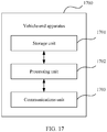
- a self-driving safety evaluation apparatus can implement functions in the method in the first aspect.
- the functions may be implemented by hardware, or may be implemented by executing corresponding software by hardware.
- the hardware or software includes units or modules that correspond to one or more of the functions.
- the apparatus includes a processor and a transceiver.
- the processor is configured to support the apparatus in performing the functions in the method in the first aspect.
- the transceiver is configured to support communication between the apparatus and another apparatus.
- the apparatus may further include a memory.
- the memory is configured to couple to the processor, and the memory stores a program instruction and data that are necessary for the apparatus.
- a computer readable storage medium stores computer program code.
- the computer program code is executed by a processing unit or a processor, a self-driving safety evaluation apparatus is enabled to perform the method in the first aspect.
- a chip is provided.
- the chip stores an instruction.
- the instruction is run on a self-driving safety evaluation apparatus, the chip is enabled to perform the method in the first aspect.
- a computer program product includes computer program code.
- the computer program code is run by a communications unit or a transceiver and a processing unit or a processor of a self-driving safety evaluation apparatus, the self-driving safety evaluation apparatus is enabled to perform the method in the first aspect.
- an apparatus for determining a driving risk of a vehicle can implement functions in the method in the second aspect.
- the functions may be implemented by using hardware, or may be implemented by executing corresponding software by hardware.
- the hardware or software includes units or modules that correspond to one or more of the functions.
- the apparatus includes a processor and a transceiver.
- the processor is configured to support the apparatus in performing the functions in the method in the first aspect.
- the transceiver is configured to support communication between the apparatus and another apparatus.
- the apparatus may further include a memory.
- the memory is configured to couple to the processor, and the memory stores a program instruction and data that are necessary for the apparatus.
- a computer readable storage medium stores computer program code.
- the computer program code is executed by a processing unit or a processor, an apparatus for determining a driving risk of a vehicle is enabled to perform the method in the second aspect.
- a chip is provided.
- the chip stores an instruction.
- the instruction is run on an apparatus for determining a driving risk of a vehicle, the chip is enabled to perform the method in the second aspect.
- a computer program product includes computer program code.
- the computer program code is run by a communications unit or a transceiver and a processing unit or a processor of an apparatus for determining a driving risk of a vehicle, the apparatus for determining a driving risk of a vehicle is enabled to perform the method in the second aspect.
- a self-driving safety evaluation system includes a risk control module, a risk policy module, and a safety evaluation module.
- the risk control module is configured to perform the method in any optional implementation of the first aspect, to determine a risk in a self-driving mode.
- the risk policy module is configured to determine a risk control policy based on the risk in the self-driving mode that is determined by the risk control module, where the risk control policy is used to reduce or eliminate the risk in the self-driving mode.
- the safety evaluation policy is used to evaluate safety in the self-driving mode based on the risk in the self-driving mode that is determined by the risk control module.
- a self-driving safety evaluation system includes a risk control module, a risk policy module, and a safety evaluation module.
- the risk control module is configured to perform the method in any optional implementation of the second aspect, to determine a risk in a self-driving mode.
- the risk policy module is configured to determine a risk control policy based on the risk that is the self-driving mode and that is determined by the risk control module, where the risk control policy is used to reduce or eliminate the risk in the self-driving mode.
- the safety evaluation policy is used to evaluate safety in the self-driving mode based on the risk in the self-driving mode that is determined by the risk control module.
- FIG. 1 is a conventional automobile product release procedure.
- the procedure includes: product planning, development, verification, release, whether a defect is exposed, and end (that is, end of manufacturing).
- a safety level requirement of a self-driving system is similar to that in a conventional automobile electronics field.
- to implement the conventional release procedure shown in FIG. 1 is difficult for the self-driving system due to an unknown potential risk introduced by self-driving and an accumulated drive test mileage (million-kilometer class) requirement introduced by driving scenario complexity.
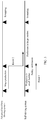
- FIG. 2 shows unknown potential risks introduced by self-driving.
- An outermost layer of circle indicates all driving scenarios, and insignificant scenarios (A area) occupy a majority of the driving scenarios.
- C area traffic accident
- B area risk scenario
- E area risk scenario
- F area new unknown potential risks
- Route 1 Automobiles on which a self-driving system is installed are produced in small batches. Safety of the self-driving system is evaluated by using a safety evaluation method, to attempt to verify the safety of the self-driving system. When safety performance of the self-driving system can meet a requirement, it is determined that a phase in which production is performed in large batches can be entered.
- Route 2 Automobiles on which an advanced auxiliary driving system is installed are produced in mass production, and safety of the advanced auxiliary driving system is evaluated by using a safety evaluation method. When a function of an advanced auxiliary driving system reaches a reliable safety level, an automobile on which the advanced auxiliary driving system is installed may be upgraded to a self-driving automobile.
- Route 1 and Route 2 respectively represent two routes for mass production of self-driving automobiles.
- the vehicle identifies, by using a risk identification method, a risk caused by a self-driving system defect, updates a risk control policy in a timely manner, and takes risk control measures before the risk develops into an accident, to reduce an accident occurrence probability.
- FIG. 4 shows a self-driving safety evaluation system according to this application.
- the system 400 includes a vehicle-end apparatus 410 and a cloud apparatus 420.
- the vehicle-end apparatus 410 includes a sensor 411, a real-time environment sensing module 412, a self-driving module 413, a shadow driving module 414, a risk identification module 415, and a risk control module 416.
- the cloud apparatus 420 includes a risk policy module 421 and a safety evaluation module 422.
- the sensor 411 is configured to collect environment information.
- the sensor 411 may be, for example, a camera or a radar.
- the real-time environment sensing module 412 is configured to process the environment information collected by the sensor 411 for subsequent use of a module. For example, the camera detects that there is an obstacle in front of the vehicle, and the radar also detects that there is an obstacle in front of the vehicle. Actually, obstacles detected by the camera and the radar may be a same obstacle. The real-time environment sensing module 412 needs to determine, based on information collected by the camera and the radar, how many obstacles there are in front actually.
- the self-driving module 413 is configured to control the vehicle to travel based on data (that is, a sensing result) output by the real-time environment sensing module 412, and output a vehicle control track of self-driving.
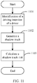
- the shadow driving module 414 is configured to: when an automobile is manually driven, simulate self-driving based on the data output by the real-time environment sensing module 412, and generate a shadow track. The following describes in detail a working process of the shadow driving module 414.
- the risk identification module 415 is configured to identify risk scenarios of manual driving, self-driving, and shadow driving, to generate risk data.
- the risk identification module 415 identifies a manual driving risk based on the sensing result output by the real-time environment sensing module 412, identifies a self-driving risk based on the vehicle control track of self-driving that is output by the self-driving module 413, and identifies a shadow driving risk based on the shadow track output by the shadow driving module 414.
- the risk policy module 421 is configured to formulate a risk control policy for the already identified potential risks of a self-driving system.
- the risk control module 416 is configured to take measures based on the risk control policy issued by the cloud to reduce or eliminate the risks.
- the safety evaluation module 422 is configured to evaluate safety of the self-driving system by using accumulated risk data.
- FIG. 4 is an example description of the system 400 from a perspective of function division.
- Functions of various modules may be implemented in a form of software, or may be implemented in a form of hardware, or may be implemented in a form of a combination of software and hardware.
- For a specific form in which the functions of the modules in the system 400 are implemented may be determined based on an actual case. This is not limited in this application.
- FIG. 4 divides the system 400 into the vehicle-end apparatus and the cloud apparatus, but an architecture of the system 400 is not limited thereto.
- the risk identification module 415 may be deployed in the cloud apparatus 420, and the vehicle-end apparatus 410 does not need to perform risk identification processing. In this way, load of a processor of the vehicle-end apparatus 410 may be reduced.
- the risk policy module and the safety evaluation module may be deployed in the vehicle-end apparatus 410. In this way, even if the vehicle-end apparatus 410 is in an offline state, the vehicle-end apparatus 410 may also formulate a risk policy based on the already identified risks caused by the self-driving system, and evaluate safety of the self-driving system.
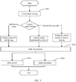
- FIG. 5 is a schematic flowchart of a self-driving safety evaluation method according to this application.
- S501 may be performed by the sensor 411.
- the sensor 411 collects real-time information, and reconstructs static and dynamic environment data, and track data of a vehicle (which may also be referred to as an "ego vehicle") in which the sensor 411 is located.
- S502 may be performed by the risk identification module 415, to identify risks in different vehicle control modes. If the ego vehicle is in a self-driving mode, the risk identification module 415 calculates a risk feature of self-driving based on a vehicle control track of self-driving. If the vehicle is in a manual driving mode, the risk identification module 415 calculates a risk feature of manual driving based on a track of vehicle control performed by a driver, and calculates a risk feature of shadow driving based on a shadow track.
- the risk control module 416 identifies a potential defect of a self-driving system based on the risk feature in the self-driving mode and the risk feature in the shadow driving mode that are obtained through calculation by the risk identification module 415, and updates the risk control policy.
- the safety evaluation module 422 evaluates safety in the self-driving mode based on accumulated risk features in various driving modes, where an evaluation result is used as a basis for safety verification and mass production and release.
- FIG. 6 shows a self-driving safety evaluation method according to this application.
- the method 600 includes the following steps.
- r b is a risk value of a vehicle in a shadow driving mode in a first measurement unit
- r c is a risk value of the vehicle in a self-driving mode based on a preset route in the first measurement unit
- the shadow driving mode is a self-driving mode of the vehicle that is based on a real-time route
- the real-time route is a route predicted based on a location and a movement parameter of the vehicle in a manual driving mode
- the first measurement unit is a time period or a distance.
- the method 600 may be performed by the cloud apparatus 420, or may be performed by a vehicle-end apparatus in which a safety evaluation module is configured.
- r b and r c reflect a probability that a risk develops into an accident, and may be a value of a probability that a risk develops into an accident, or may be another type of value that can be used to quantify a self-driving risk.
- Measurement units of r b and r c may be time periods, or may be distances.
- a risk behavior may be defined as an explicit or implicit driving behavior (including manual driving, self-driving, and shadow driving) that violates a safety goal. "Explicit” indicates that a driving behavior has developed into an accident, and “implicit” indicates that a driving behavior may develop into an accident. Therefore, identification of the risk behavior includes the following:
- Identification of an explicit risk for example, a collision or violating a red and green light rule.
- the implicit risk further includes abnormal driving behaviors. These driving behaviors may cause a failure of timely reaction by another vehicle, resulting in a passive accident, for example, an abnormal acceleration or deceleration and not travelling in a road direction.
- Automatic identification of a risk scenario can be achieved by defining and calculating features of these risk behaviors in corresponding scenarios.
- the safety goal includes but is not limited to the following definitions:
- a risk value may be defined as 1; when no risk occurs, a risk value may be defined as 0; and a risk value of an implicit risk is a value greater than 0 and less than 1.
- the first measurement unit is any measurement unit.
- the self-driving mode based on the preset route is the self-driving mode shown in FIG. 5 .
- the mode is a driving mode in which the self-driving module 413 controls a vehicle. After obtaining a start point and an end point of a distance (that is, the preset route), the self-driving module 413 controls the vehicle to travel the distance, and a driver does not participate in driving.
- the driving mode based on the real-time route is a self-driving mode simulated by the shadow driving module 414 in a process in which the driver controls the vehicle to travel.
- the shadow driving module 414 continuously corrects a shadow track based on a location and a movement parameter of the vehicle that exist when vehicle control is performed by the driver, to avoid a case in which a route of self-driving passes through a B street while a route of vehicle control performed by the driver passes through an A street, so that safety evaluation on self-driving is more objective.
- R B may be, for example, an average value obtained by dividing a sum of r b of the plurality of measurement units by the plurality of measurement units, or may be an average value obtained by dividing a sum of products of r b of all measurement units and a weighting coefficient by the plurality of measurement units.
- R C may be, for example, an average value obtained by dividing a sum of r c of the plurality of measurement units by the plurality of measurement units, or may be an average value obtained by dividing a sum of products of r c of all measurement units and a weighting coefficient by the plurality of measurement units.
- R B and R C may alternatively be values obtained through calculation by using another method, and a method for calculating R B and R C is not limited in this application.
- the risk data generated by the self-driving mode based on the real-time route is further collected.
- the real-time route is the self-driving route (that is, the shadow track) predicted based on the location and the movement parameter of the vehicle in the manual driving mode.
- the shadow driving module 414 may re-plan the self-driving route based on the route of vehicle control performed by the driver, and determine safety of self-driving based on the re-planned self-driving route, thereby more truly evaluating the safety of self-driving.
- the method 600 further includes the following steps.
- the foregoing embodiment may be implemented by an apparatus for determining R B and R C , without a need of sending R B and R C to another device and evaluating, by the another device, safety of the vehicle in the self-driving mode, thereby improving real-time performance of safety evaluation on the self-driving mode.
- the self-driving risk threshold is a threshold of a risk value in the self-driving mode in each measurement unit.
- the self-driving risk threshold may be a value that is set based on a statistical result, for example, a maximum value of average self-driving risk values per kilometer in a mileage of one million kilometers travelled by the vehicle. If the value of R B + R C is less than or equal to the maximum value after the vehicle travels the one million kilometers, a self-driving function of the vehicle meets the safety requirement, and mass production can be implemented. If the value of R B + R C is greater than the maximum value after the vehicle travels the one million kilometers, the self-driving function of the vehicle cannot meet the safety requirement, mass production cannot be implemented, and improvement needs to be made.
- Mileages respectively corresponding to R B and R C in R B + R C may be set for every million kilometers.
- the mileage corresponding to R C in R B + R C may be set to be no less than one hundred thousand kilometers for every million kilometers, so that the safety of self-driving can be more objectively and truly evaluated.
- the self-driving risk threshold is a ( R A + R' A ), where a is a risk tolerance coefficient, R A is, for example, an average value of risk values of the vehicle in the manual driving mode in the plurality of measurement units, a road section through which the vehicle passes in the plurality of measurement units is a first road section, and R ' A is, for example, an average value of risk values of the vehicle passing through the first road section outside the plurality of measurement units based on the manual driving mode.
- a risk value of self-driving may be compared with a risk value of manual driving, and a tolerance coefficient that the risk value of the self-driving can be accepted may be set, to determine whether safety of self-driving satisfies a requirement.
- R A is a risk value obtained after the vehicle travels five hundred thousand kilometers in the manual driving mode, a road section through which the vehicle travels the five hundred thousand kilometers is a first road section, and R' A is a risk value obtained after the vehicle passes through the first road section again in the manual driving mode.
- R B + R C is a risk value obtained after the vehicle travels one million kilometers in the self-driving mode.
- a indicates that when travelled distances have a same length, the risk value of self-driving needs to be less than a product of the risk value of manual driving and a , and only in this case, it can be determined that the safety in the self-driving mode meets the requirement, and a is usually a constant greater than 0 and less than 1.
- the determining R B based on r b and the determining R C based on r c include the following step.
- s event reflects severity degrees of accidents in different risk scenarios
- r i reflects a probability that a risk develops into an accident
- ⁇ reflects an accumulation of risks of the plurality of measurement units.
- s event in a case of colliding with a person may be set to 1, and s event in a case of colliding with another object may be selected from 0.1 to 0.9 based on a property of the object.
- s event may be defined based on accident statistics data.
- corresponding s event is equal to 0.01.
- X may be a mileage travelled by the vehicle or a time for which the vehicle travels, where the mileage or the time corresponds to R i , and R i reflects an average probability that a risk develops into an accident in each measurement unit (for example, per kilometer or per hour).
- R i reflects an average probability that a risk develops into an accident in each measurement unit (for example, per kilometer or per hour).
- the foregoing formula can objectively reflect a self-driving risk.
- the obtaining r b and r c includes the following steps.
- r b and r c based on at least one of the following parameters: a speed ⁇ v of the vehicle relative to a collision object, a time to collision TTC between the vehicle and the collision object that is estimated based on a movement track of the collision object, a time to headway THW of the vehicle that is estimated based on a distance between the vehicle and the collision object, and the distance between the vehicle and the collision object, where ⁇ v is positively correlated to r b or r c , the TTC is negatively correlated to r b or r c , the THW is negatively correlated to r b or r c , and the distance between the vehicle and the collision object is negatively correlated to r b or r c .
- a higher relative movement speed indicates a higher probability that a risk develops into an accident, that is, ⁇ v is positively correlated to r b or r c ;
- a longer time to collision indicates a higher possibility of adjusting a travelling route by the vehicle to avoid a collision and a lower probability of occurrence of a collision, and therefore TTC is negatively correlated to r b or r c ;
- a longer available time to headway indicates a smaller probability of occurrence of a collision, and therefore THW is negatively correlated to r b or r c ;
- a longer distance between the vehicle and the collision object indicates a higher possibility of adjusting the travelling route by the vehicle to avoid a collision and a lower probability of occurrence of a collision, and therefore the distance between the vehicle and the collision object is positively correlated to r b or r c .
- FIG. 7 is a schematic diagram of a risk in a collision scenario according to this application.
- a track of an ego vehicle is a line segment from a state (t2, s2, v2, a2) to a state (t0, s0, v0, a0), and a track of another vehicle is a line segment from a state (t1, s1, v1, a1) to a state (t'0, s'0, v'0, a'0).
- the two vehicles travel toward each other, and collide at a cross point of the two lines shown in the figure.
- Both the foregoing two tracks are tracks predicted by the ego vehicle.
- the ego vehicle identifies, based on a sensing result of a sensor, an object that has an intersection with the track of the ego vehicle in a future time period (for example, five seconds).
- a maximum value of risk values of collision between the ego vehicle and the foregoing object is used as a collision risk value in the future time period.
- h ( t event ,obj) represents that a collision risk event ( obj ) causes a potential collision event in a time period ( t event )
- h ( t event ,obj ) represents that occurrence of a collision risk event ( obj ) causes an increase in a probability of occurrence of a collision in a time period ( t event )
- h ( t event ,obj ) 0 represents that no collision risk event occurs.
- Each normalized parameter is used to indicate a weight of each parameter. For example, each normalized parameter may be a value greater than or equal to 0 and less than or equal to 1.
- a relative speed of the two vehicles is greater than 40 km/h
- a collision occurs, there is an extremely high probability of personal casualty.
- an expected collision time (that is, TTC) of the two vehicles is less than 1s, there is an extremely high probability that a collision between the two vehicles cannot be avoided.
- TTC expected collision time
- THW is less than 1s, if the another vehicle is braking, there is an extremely high probability that the ego vehicle cannot avoid a collision between the two vehicles.
- a collision occurrence moment may be predicted, and a time period ( t event ) near the predicted collision occurrence moment may be selected to calculate a collision risk value (a collision occurrence probability) in the time period.
- a maximum value that is, f ( t ) max ) of a plurality of collision risk values in the time period is used as the collision risk value in the time period.
- the obtaining r b and r c includes the following steps.
- the risk scenario is a traffic signal light scenario
- a higher speed of the vehicle indicates a higher probability of violating a traffic signal light (for example, running a red light), and therefore the speed of the vehicle is positively correlated to r b or r c ; and a longer distance from the vehicle to the traffic signal light indicates a longer time used by the vehicle to change a travelling status and a lower probability of running the traffic signal light, and therefore the distance from the vehicle to the traffic signal light is negatively correlated to r b or r c .
- a traffic signal light for example, running a red light
- FIG. 8 is a schematic diagram of a risk in a traffic signal light scenario according to this application.
- a risk in the traffic signal light scenario is mainly violation of a rule indicated by a traffic signal light, and a corresponding risk value may be obtained based on a speed of an ego vehicle.
- a distance of 50 m between the ego vehicle and the traffic signal light, a distance s from the vehicle to a stop line at an intersection, a speed v of the ego vehicle, and an acceleration a of the vehicle constitute an ego vehicle status.
- the right diagram shows a distance-speed curve of the ego vehicle.
- the traffic signal light shows a no-passing signal
- the ego vehicle needs to decelerate, and reduce the speed to 0 before the stop line.
- Different accelerations constitute different speed-distance curves.
- the common acceleration is an acceleration whose absolute value is less than an absolute value of a preset acceleration.
- a value of the preset acceleration is 0.4 g, and the ego vehicle can stop before the stop line if using an acceleration of -0.3 g.
- r b or r c of the ego vehicle is equal to 0.
- h ( t event , Light ) represents that a probability of occurrence of violating a traffic signal light increases in a time period ( t event ) due to occurrence of a traffic signal light risk event ( Light )
- a risk event usually lasts for a time period from occurrence to disappearance.
- the vehicle-end apparatus 410 or the cloud apparatus 420 may select a time period t event near a moment at which the risk event is identified, to calculate a risk value in the time period.
- the time period includes the moment at which the collision risk event is identified.
- the normalized parameter is used to represent a weight of a parameter.
- each normalized parameter may be a value greater than or equal to 0 and less than or equal to 1.
- a traffic signal light at the intersection displays a no-passing signal
- a speed of the vehicle is 100 km/h
- there is an extremely high probability of occurrence of a risk of running the traffic signal light for example, running a red light
- the foregoing "the vehicle is 50 m away from the intersection, a traffic signal light at the intersection displays a no-passing signal, and a speed of the vehicle is 100 km/h” are traffic signal light risk events ( Light ).
- a moment at which a red light is run may be predicted, and a time period ( t event ) near the predicted moment at which the red light is run may be selected to calculate a red light running risk value (that is, a probability of occurrence of running the red light) in the time period.
- a red light running risk value that is, a probability of occurrence of running the red light
- a maximum value that is, f ( t ) max ) of a plurality of red light running risk values in the time period is selected as a red light running risk value in the time period.
- the obtaining r b and r c includes the following steps.
- the risk scenario is a scenario in which the vehicle rushes out of a road boundary
- the estimated time taken by the vehicle to rush out of the lane is negatively correlated to r b or r c .
- the obtaining r b and r c includes the following steps.
- the risk scenario is a non-conventional travelling scenario (for example, a travelling scenario in which the vehicle currently has a lateral acceleration)
- determine r b and r c based on at least one of the following parameters: a longitudinal acceleration of the vehicle, a lateral acceleration of the vehicle, and a speed of the vehicle, where the longitudinal acceleration of the vehicle is positively correlated to r b or r c , the lateral acceleration of the vehicle is positively correlated to r b or r c , and the speed of the vehicle is positively correlated to r b or r c .
- the longitudinal acceleration is an acceleration whose acceleration direction is the same as or opposite to a speed direction (for example, an acceleration obtained by stepping on an accelerator or stepping on a brake during straight travelling).
- the lateral acceleration is an acceleration whose acceleration direction has a non-zero angle with a speed direction (for example, an acceleration that causes a drift of the vehicle when the vehicle is turning).
- a larger longitudinal acceleration indicates a higher probability of overspeed of the vehicle or an abrupt brake of the vehicle. Therefore, the longitudinal acceleration of the vehicle is positively correlated to r b or r c .
- a larger lateral acceleration indicates a higher probability of abrupt turning of the vehicle. Therefore, the lateral acceleration of the vehicle is positively correlated to r b or r c .
- a higher speed of the vehicle indicates a higher probability of occurrence of non-conventional travelling such as overspeed. Therefore, the speed of the vehicle is positively correlated to r b or r c .
- represents an absolute value of the lateral acceleration of the vehicle,
- a threshold 1 represents a threshold of the lateral acceleration in a safe driving status, for example, may be 0.5 g
- the cloud apparatus 420 does not need to perform S611 to S614. If information received by the cloud apparatus 420 from the vehicle-end apparatus 410 is data sensed by the sensor, the cloud apparatus 420 further needs to perform S611 to S614 to obtain r b and r c .
- an important factor affecting a technical effect of the self-driving safety evaluation method is whether a risk value can reflect an actual risk level.
- the following describes in detail a method for determining a driving risk of a vehicle provided in this application.
- FIG. 9 shows a method for determining a driving risk of a vehicle according to this application.
- the method 900 is applied to a vehicle having a self-driving mode and a manual driving mode, and the method 900 includes the following steps.
- S910 Determine a driving mode and a risk scenario of the vehicle in a time period, where a start point of the time period is a first moment, an end point of the time period is a second moment, and the driving mode includes the self-driving mode and/or the manual driving mode.
- S920 Determine a risk value in the driving mode in the time period based on a risk identification manner corresponding to the risk scenario at a current moment, where the current moment is after the first moment, and the current moment is before the second moment.
- the method 900 may be performed, for example, by the vehicle-end apparatus 410.
- the vehicle-end apparatus 410 selects a time period from a plurality of time periods required for the vehicle to travel a distance, and determines, at a moment (that is, the current moment) in the time period, a risk value in a corresponding driving mode in the time period by using known travelling information and predicted travelling information. For example, the determined time period is one second, and the current moment is a moment of 0.4 seconds. If an overspeed travelling status occurs in the past 0.4 seconds, the vehicle may determine that the risk value of non-conventional driving in the driving mode in the time period is 1, that is, a probability of occurrence of overspeed is 100%.
- the vehicle may determine that the risk value of non-conventional driving in the time period is a value less than 1, that is, the probability of occurrence of overspeed is less than 100%.
- a time period required for travelling a distance is divided into the plurality of time periods, and a risk value in a driving mode in each time period is determined based on a traffic context (that is, information related to a traffic environment before a current moment and after the current moment) in the time period, so that the risk can be more objectively identified.
- the vehicle-end apparatus 410 may alternatively determine a time period by using another method, for example, determine, based on a distance and a speed, a time period required for travelling the distance.
- the time period is the "time period" described in S910.
- the first moment and the second moment are determined at the current moment, so that the "time period" described in S910 is determined.
- the risk value in the self-driving mode and/or the manual driving mode can be determined.
- the self-driving mode includes the shadow driving mode, and evaluating the safety of the self-driving system based on the risk value in the shadow driving mode is an important factor that enables the self-driving safety evaluation method provided in this application to achieve a better technical effect compared with that in the prior art.
- a purpose of the shadow driving mode is to generate a simulated vehicle control track of self-driving by using software and hardware that are run in a system background in the manual driving mode, to identify a potential risk of the self-driving system, and further identify a potential risk of the self-driving system, and accumulate data required by safety evaluation.
- a main difficulty is that when the vehicle is in the manual driving mode, a self-driving module cannot really control the vehicle, and how a shadow track approaches an actual risk level of the self-driving system.
- the vehicle control track of self-driving directly generated based on sensed data of a sensor cannot represent the real risk level of the self-driving system. Consequently, distortion of a self-driving safety evaluation result is caused.
- FIG. 10 is a schematic diagram of a vehicle control track of self-driving.
- a dashed-line arrow represents an actual track of a vehicle in a manual driving mode.
- a solid-line arrow represents a self-driving track simulated based on sensed data of a sensor. Because the sensed data indicates that there is another vehicle on a left lane, the self-driving system simulates a track used by the vehicle to continue to travel along an original lane. Actually, the vehicle does not travel along the original lane but changes a lane.
- the self-driving track simulated based on the sensed data of the sensor cannot reflect a real driving status, causing distortion of a result of self-driving safety evaluation that is based on the track.
- the method 900 further includes the following steps.
- S920 includes the following step.
- the vehicle may predict a location of the vehicle after a future time period based on the location and the movement parameter of the vehicle at the first moment, that is, predict a location of the vehicle at the third moment.
- the vehicle is in a manual driving status at the first moment, and subsequently, the vehicle predicts the shadow driving mode of the vehicle from the location at the first moment to the location at the third moment.
- a route of self-driving is continuously modified based on the location and the movement parameter in the manual driving mode, to enable the route in the self-driving mode to be closer to a route in the manual driving mode. Therefore, more objective self-driving risk data can be obtained.
- the third moment may be the current moment described in S920, or may be the second moment, or may be a moment after the second moment.
- FIG. 11 is a flowchart of a shadow driving mode according to this application.
- the shadow driving module 414 identifies, at a first moment, a driving intention of the driver based on a movement parameter (for example, a speed and an acceleration) of the vehicle, that is, the content described in S901 to S903, and then uses the identified driving intention of the driver as input information of the shadow driving mode 414, to generate a shadow track, thereby improving a degree of overlap between the shadow track and a track of vehicle control performed by the driver.
- a movement parameter for example, a speed and an acceleration
- the driving intention of the driver includes but is not limited to: at least one of travelling along a current lane, turning, and changing a lane.
- FIG. 12 is a flowchart of a method for identifying an intention of a driver according to this application.
- the information at the future moment is predicted by using the current information, and the current driving intention of the driver is determined by using the predicted information at the future moment, thereby eliminating a deviation caused by determining the intention of the driver based on sensed data of a sensor.
- FIG. 13 is a schematic diagram of predicting a shadow track based on a shadow driving mode according to this application.
- the shadow track shown in FIG. 13 is approximately the same as a track of vehicle control performed by a driver, but has a slight difference. Different risk values are respectively obtained based on the track of vehicle control performed by the driver and the shadow track, and which of a manual driving mode and a self-driving mode is safer may be estimated based on a difference between the risk values.
- the shadow driving module 414 when a driving intention of the driver is a risk intention (for example, aggressive cutting in), if correctly identifying a risk in this case, the shadow driving module 414 generates no shadow track conforming to the driving intention of the driver, but generates a shadow track by selecting a safer decision (for example, keeping travelling in a right direction in a lane).
- a safer decision for example, keeping travelling in a right direction in a lane.
- FIG. 14 is a schematic diagram of the risk value of the shadow track that is calculated in the step of calculating a shadow track shown in FIG. 11 .
- a solid line represents the risk value obtained based on the track of vehicle controlled by the driver that is calculated in S611 to S614, and a dashed line is a risk value calculated based on a shadow track corresponding to each time period (for example, a time period from the first moment to the third moment) in S611 to S614.
- the track of vehicle control performed by the driver continuously falls into the risk area, and the shadow track returns from the risk area to the safe area. This indicates that a travelling risk is reduced through simulated controlling of the vehicle performed by the system, and the data may be used as an evidence that safety performance of the self-driving system is higher than that of vehicle control performed by the driver.
- both the track of vehicle control performed by the driver and the vehicle control shadow track continuously fall into the risk area, but the risk value of the shadow track is less than that of the track of vehicle control performed by the driver.
- a shadow track generation method is consistent with an algorithm of vehicle control of self-driving
- a method for calculating a risk of the shadow track is consistent with a method for calculating a risk of a self-driving/driver driving track, so that it can be ensured that a shadow track risk represents a self-driving system risk.
- the method 900 further includes:
- the vehicle may send the foregoing risk data to the safety center after obtaining r a , r b , or r c , so that the safety center evaluates the safety in the manual driving mode and the shadow driving mode, thereby reducing an operating load of an in-vehicle processor.
- the security center is, for example, the cloud apparatus 420.
- evaluating safety of the self-driving automobile in a self-driving mode is a long-term process. Even if evaluation of the safety in the self-driving mode is passed, it does not mean that the self-driving mode is 100% safe. Therefore, it is necessary to design a solution for immediate control of a risk, that is, to reduce or eliminate the risk through the risk control module 416.
- FIG. 15 is a schematic flowchart of a risk control method according to this application.
- risk scenario data includes but is not limited to at least one of sensing data obtained by the sensor 411, a track generated by the self-driving module 413, or a track generated by the shadow driving module 414.
- the risk identification module 415 determines, based on the risk scenario data, whether a current scenario is a risk scenario. If the risk identification module 415 determines that the current scenario is a non-risk scenario, but it is found that the current scenario is actually a risk scenario afterwards, a risk identification mechanism may be adjusted, for example, a risk identification threshold parameter may be adjusted and a risk identification algorithm may be modified.
- the risk identification module 415 confirms that the current scenario is a risk scenario and determines that the risk scenario is caused by a potential risk of a self-driving system, the risk identification module 415 reports the risk scenario to the risk policy module 421.
- the risk policy module 421 sends policy update information to the risk control module 416, updates the risk control policy of the vehicle-end apparatus 410, and excludes the risk scenario from the safe scenario fence.
- the method 900 further includes the following steps.
- the vehicle plays and/or displays prompt information prompting the driver to perform manual driving, and/or the vehicle performs safe stopping processing.
- the safety center may identify a risk scenario based on the risk data reported by the vehicle, and update a risk identification mechanism and a risk control policy of the vehicle by sending the safety scenario information to the vehicle. For example, if a risk is caused by a potential risk of the self-driving system, the safety scenario information may instruct the vehicle to exclude the risk scenario from the safe driving traffic scenario set.
- the vehicle updates the safe driving traffic scenario set after receiving the safety scenario information. If the current traffic scenario does not belong to the updated safe driving traffic scenario set, the vehicle takes safety measures, for example, plays and/or displays prompt information prompting the driver to perform manual driving, and/or performs safe stopping processing.
- the safe driving traffic scenario set may also be referred to as a safe driving scenario fence, and includes an environment, a static scenario, a dynamic scenario, and a behavior of an ego vehicle.
- a definition of the scenario fence is shown in FIG. 16 .
- content in round brackets is content included in a safe driving scenario fence of a self-driving system.
- the cloud apparatus 420 transmits safety scenario information based on an identified potential risk of the self-driving system in a timely manner, to update content in the safe driving scenario fence.
- the risk control module 416 obtains an identified result of each element of the scenario fence based on map input and a real-time sensing result, and updates content in the safe driving scenario fence based on the safety scenario information sent by the cloud apparatus 420.
- the self-driving module 413 In a process of controlling, by the self-driving module 413, a vehicle to travel, if the risk control module 416 determines that a current scenario exceeds a safe driving scenario fence range, the self-driving module 413 prompts a driver to take over the vehicle, or controls the vehicle to stop in a safe zone.
- a risk event is that a potential risk is caused due to that the system cannot accurately identify a type of a red and green light because of an intersection width greater than 20 m.
- the intersection width is less than 20 m.
- a risk event is that a potential risk is caused due to that the self-driving system cannot measure a speed of a low-speed vehicle in time.
- an applicable vehicle flow speed in a dynamic scenario is from 10 to 50 kilometers per hour (kph).
- the self-driving system prompts the driver to take over the vehicle, or gently pulls over the vehicle.
- a driver in-the-loop policy may alternatively be adjusted, for example, an alerting interval may be adjusted.
- the vehicle-end apparatus and the cloud apparatus include corresponding hardware structures and/or software modules for performing the functions.
- a person of ordinary skill in the art should be easily aware that, in combination with the examples described in the embodiments disclosed in this specification, units and algorithms steps may be implemented by hardware or a combination of hardware and computer software in this application. Whether a function is performed by hardware or hardware driven by computer software depends on particular applications and design constraints of the technical solutions. A person skilled in the art may use different methods to implement the described functions for each particular application, but it should not be considered that the implementation goes beyond the scope of this application.
- function unit division may be performed on the vehicle-end apparatus and the cloud apparatus based on the foregoing method examples.
- each function unit may be obtained through division based on a corresponding function, or two or more functions may be integrated into one processing unit.
- the integrated unit may be implemented in a form of hardware, or may be implemented in a form of a software function unit.
- unit division is an example, and is merely a logical function division. In actual implementation, another division manner may be used.
- FIG. 17 is a possible schematic structural diagram of the vehicle-end apparatus in the foregoing embodiments.
- the vehicle-end apparatus 1700 includes: a processing unit 1702 and a communications unit 1703.
- the processing unit 1702 is configured to control and manage an action of the vehicle-end apparatus 1700.
- the processing unit 1702 is configured to support the vehicle-end apparatus 1700 in performing S620 and/or another process used for the technology described in this specification.
- the communications unit 1703 is configured to support communication between the vehicle-end apparatus 1700 and a cloud apparatus.
- the vehicle-end apparatus 1700 may further include a storage unit 1701, configured to store program code and data of the vehicle-end apparatus 1700.
- the processing unit 1702 is configured to perform S610 to S630.
- the processing unit 1702 may also be referred to as an obtaining unit 1702.
- the storage unit 1701 needs to store intermediate data generated in a process in which the processing unit 1702 performs the foregoing steps.
- the intermediate data is r b and r c , so that the processing unit 1702 determines, based on a risk value in a shadow driving mode in a plurality of measurement units and a risk value in a self-driving mode based on a preset route, whether safety of a vehicle in the self-driving mode meets a requirement.
- the processing unit 1702 is configured to perform S610, and control the communications unit 1703 to send r b and r c to the cloud apparatus, so that the cloud apparatus performs S620 and S630.
- the processing unit 1702 is configured to control the communications unit 1703 to send, to a cloud apparatus, original data (for example, sensor data) used for calculating r b and r c , so that the cloud apparatus performs S610 to S630.
- original data for example, sensor data
- the processing unit 1702 is configured to perform S910 and S920.
- the processing unit 1702 is configured to control the communications unit 1703 to perform S930.
- the processing unit 1702 may be a processor or a controller, for example, may be a central processing unit (central processing unit, CPU), a general-purpose processor, a digital signal processor (digital signal processor, DSP), an application-specific integrated circuit (application-specific integrated circuit, ASIC), a field programmable gate array (field programmable gate array, FPGA), or another programmable logical device, a transistor logical device, a hardware component, or a combination thereof.
- the processor may implement or execute various example logical blocks, modules, and circuits described with reference to content disclosed in this application. Alternatively, the processor may be a combination for implementing a computing function, for example, a combination of one or more microprocessors, or a combination of the DSP and a microprocessor.
- the communications unit 1703 may be a transceiver or the like.
- the storage unit 1701 may be a memory.
- the vehicle-end apparatus in this application may be a vehicle-end apparatus 1800 shown in FIG. 18 .
- the vehicle-end apparatus 1800 includes: a processor 1802, a transceiver 1803, and a memory 1801.
- the transceiver 1803, the processor 1802, and the memory 1801 may communicate with each other through an internal connection path, and transmit a control signal and/or a data signal.
- FIG. 19 is a possible schematic structural diagram of the cloud apparatus described in the foregoing embodiments.
- the cloud apparatus 1900 includes: a processing unit 1902 and a communications unit 1903.
- the processing unit 1902 is configured to control and manage an action of the cloud apparatus 1900.
- the processing unit 1902 is configured to support the cloud apparatus 1900 in performing S620 and/or another process used for the technology described in this specification.
- the communications unit 1903 is configured to support communication between the cloud apparatus 1900 and a vehicle-end apparatus.
- the cloud apparatus 1900 may further include a storage unit 1901, configured to store program code and data of the cloud apparatus 1900.
- the processing unit 1902 is configured to control the communications unit 1903 to perform S610, that is, receive r b and r c from the vehicle-end apparatus.
- the communications unit 1903 may also be referred to as an obtaining unit 1903, and the processing unit 1902 is further configured to perform S620 to S641.
- the storage unit 1901 needs to store intermediate data generated in a process in which the processing unit 1902 performs the foregoing steps.
- the intermediate data is r b and r c , so that the processing unit 1902 determines, based on a risk value in a shadow driving mode in a plurality of measurement units and a risk value in a self-driving mode based on a preset route, whether safety of a vehicle in the self-driving mode meets a requirement.
- the processing unit 1902 is configured to control the communications unit 1903 to receive, from the vehicle-end apparatus, original data (for example, sensor data) used for calculating r b and r c .
- the processing unit 1902 is further configured to obtain r b and r c based on the original data received by the communications unit 1903.
- the processing unit 1902 may also be referred to as an obtaining unit 1902.
- the processing unit 1902 is further configured to perform S620 to S641.
- the storage unit 1901 needs to store intermediate data generated in a process in which the processing unit 1902 performs the foregoing steps.
- the intermediate data is r b and r c , so that the processing unit 1902 determines, based on a risk value in a shadow driving mode in a plurality of measurement units and a risk value in a self-driving mode based on a preset route, whether safety of a vehicle in the self-driving mode meets a requirement.
- the processing unit 1902 is configured to perform S910 and S920.
- the processing unit 1902 is configured to control the communications unit 1903 to perform S930.
- the processing unit 1902 may be a processor or a controller, for example, may be a CPU, a general-purpose processor, a DSP, an ASIC, an FPGA, or another programmable logic device, a transistor logic device, a hardware component, or any combination thereof.
- the processor may implement or execute various example logical blocks, modules, and circuits described with reference to content disclosed in this application.
- the processor may be a combination for implementing a computing function, for example, a combination of one or more microprocessors, or a combination of the DSP and a microprocessor.
- the communications unit 1903 may be a transceiver or the like.
- the storage unit 1901 may be a memory.
- the cloud apparatus in this application may be a cloud apparatus 2000 shown in FIG. 20 .
- the cloud apparatus 2000 includes: a processor 2002, a transceiver 2003, and a memory 2001.
- the transceiver 2003, the processor 2002, and the memory 2001 may communicate with each other through an internal connection path, and transmit a control signal and/or a data signal.
- This application further provides a self-driving safety evaluation system, including the foregoing one or more vehicle-end apparatuses and one or more cloud apparatuses.
- the processor in this embodiment of this application may be an integrated circuit chip, and has a signal processing capability.
- steps in the foregoing method embodiments can be implemented by using a hardware integrated logical circuit in the processor, or by using instructions in a form of software.
- the foregoing processor may be a general-purpose processor, a digital signal processor (digital signal processor, DSP), an application-specific integrated circuit (application specific integrated circuit, ASIC), a field programmable gate array (field programmable gate array, FPGA) or another programmable logical device, a discrete gate or transistor logic device, or a discrete hardware component.
- DSP digital signal processor
- ASIC application specific integrated circuit
- FPGA field programmable gate array
- the processor may implement or perform the methods, the steps, and logical block diagrams that are disclosed in the embodiments of this application.
- the general-purpose processor may be a microprocessor, or the processor may be any conventional processor or the like. Steps in the methods disclosed with reference to the embodiments of this application may be directly executed and accomplished by using a hardware decoding processor, or may be executed and accomplished by using a combination of hardware and software modules in the decoding processor.
- the software module may be located in a mature storage medium in the art, such as a random access memory, a flash memory, a read-only memory, a programmable read-only memory, an electrically erasable programmable memory, or a register.
- the storage medium is located in the memory, and the processor reads information in the memory and completes the steps in the foregoing methods in combination with hardware of the processor.
- the memory in this embodiment of this application may be a volatile memory or a nonvolatile memory, or may include a volatile memory and a nonvolatile memory.
- the nonvolatile memory may be a read-only memory (read-only memory, ROM), a programmable read-only memory (programmable ROM, PROM), an erasable programmable read-only memory (erasable PROM, EPROM), an electrically erasable programmable read-only memory (electrically EPROM, EEPROM), or a flash memory.
- the volatile memory may be a random access memory (random access memory, RAM), used as an external cache.
- RAMs may be used, for example, a static random access memory (static RAM, SRAM), a dynamic random access memory (dynamic RAM, DRAM), a synchronous dynamic random access memory (synchronous DRAM, SDRAM), a double data rate synchronous dynamic random access memory (double data rate SDRAM, DDR SDRAM), an enhanced synchronous dynamic random access memory (enhanced SDRAM, ESDRAM), a synchronous link dynamic random access memory (synchlink DRAM, SLDRAM), and a direct rambus random access memory (direct rambus RAM, DR RAM).
- static random access memory static random access memory
- DRAM dynamic random access memory
- DRAM dynamic random access memory
- SDRAM synchronous dynamic random access memory
- double data rate SDRAM double data rate SDRAM
- DDR SDRAM double data rate SDRAM
- ESDRAM enhanced synchronous dynamic random access memory
- SLDRAM synchronous link dynamic random access memory
- direct rambus RAM direct rambus RAM
- This application further provides a computer readable medium.
- the computer readable medium stores a computer program. When being executed by a computer, the computer program implements the function of any one of the foregoing method embodiments.
- This application further provides a computer program product.
- the computer program product When being executed by a computer, the computer program product implements the function of any one of the foregoing method embodiments.
- All or some of the foregoing embodiments may be implemented by using software, hardware, firmware, or any combination thereof.
- the embodiments may be implemented completely or partially in a form of a computer program product.
- the computer program product includes one or more computer instructions.
- the computer may be a general-purpose computer, a dedicated computer, a computer network, or other programmable apparatuses.
- the computer instructions may be stored in a computer-readable storage medium or may be transmitted from a computer-readable storage medium to another computer-readable storage medium.
- the computer instructions may be transmitted from a website, computer, server, or data center to another website, computer, server, or data center in a wired (for example, a coaxial cable, an optical fiber, or a digital subscriber line (digital subscriber line, DSL)) or wireless (for example, infrared, radio, or microwave) manner.
- the computer-readable storage medium may be any usable medium accessible by the computer, or a data storage device, such as a server or a data center, integrating one or more usable media.
- the usable medium may be a magnetic medium (for example, a floppy disk, a hard disk, or a magnetic tape), an optical medium (for example, a high density digital versatile disc (digital versatile disc, DVD), a semiconductor medium (for example, a solid-state drive (solid state disk, SSD)), or the like.
- a magnetic medium for example, a floppy disk, a hard disk, or a magnetic tape
- an optical medium for example, a high density digital versatile disc (digital versatile disc, DVD)
- a semiconductor medium for example, a solid-state drive (solid state disk, SSD)
- This application further provides a processing apparatus, including a processor and an interface.
- the processor is configured to perform the steps described in any one of the foregoing method embodiments.
- the processing apparatus may be a chip, and the processor may be implemented by hardware, or may be implemented by software.
- the processor When implemented by hardware, the processor may be a logic circuit, an integrated circuit, or the like.
- the processor When implemented by software, the processor may be a general-purpose processor, and is implemented by reading software code stored in a memory.
- the memory may be integrated in the processor, or may exist independently outside the processor.
- system and “network” may be used interchangeably in this specification.
- the term “and/or” in this specification describes only an association relationship for describing associated objects and represents that three relationships may exist. For example, A and/or B may represent the following three cases: Only A exists, both A and B exist, and only B exists.
- the character "/" in this specification generally indicates an “or” relationship between the associated obj ects.
- B corresponding to A indicates that B is associated with A, and B may be determined according to A.
- determining B according to A does not mean that B is determined only according to A; that is, B may also be determined according to A and/or other information.
- the disclosed system, apparatus, and method may be implemented in other manners.
- the described apparatus embodiment is merely an example.
- the unit division is merely logical function division and may be other division in actual implementation.
- a plurality of units or components may be combined or integrated into another system, or some features may be ignored or not performed.
- the displayed or discussed mutual couplings or direct couplings or communication connections may be implemented through some interfaces, indirect couplings or communication connections between the apparatuses or units, or electrical connections, mechanical connections, or connections in other forms.
- the units described as separate parts may or may not be physically separate, and parts displayed as units may or may not be physical units, may be located in one position, or may be distributed on a plurality of network units. Some or all of the units may be selected according to actual requirements to achieve the objectives of the solutions of the embodiments in this application.
- function units in the embodiments of this application may be integrated into one processing unit, or each of the units may exist alone physically, or two or more units are integrated into one unit.
- the integrated unit may be implemented in a form of hardware, or may be implemented in a form of a software function unit.
- the computer-readable medium includes a computer storage medium and a communications medium, where the communications medium includes any medium that enables a computer program to be transmitted from one place to another.
- the storage medium may be any available medium accessible to a computer. The following provides an example but does not impose a limitation.
- the computer-readable medium may include a RAM, a ROM, an EEPROM, a CD-ROM or another optical disc storage, a disk storage medium or another magnetic storage device, or any other medium that can carry or store expected program code in a form of an instruction or a data structure and can be accessed by a computer.
- any connection may be appropriately defined as a computer-readable medium.
- a disk (Disk) and disc (disc) used by this application include a compact disc (CD), a laser disc, an optical disc, a digital versatile disc (DVD), a floppy disk, and a Blu-ray disc, where the disk generally copies data magnetically, and the disc copies data optically by using laser.
- CD compact disc
- DVD digital versatile disc
- floppy disk a compact disc
- Blu-ray disc where the disk generally copies data magnetically, and the disc copies data optically by using laser.
Landscapes
- Engineering & Computer Science (AREA)
- Business, Economics & Management (AREA)
- Automation & Control Theory (AREA)
- Mechanical Engineering (AREA)
- Transportation (AREA)
- Human Resources & Organizations (AREA)
- Physics & Mathematics (AREA)
- Economics (AREA)
- Strategic Management (AREA)
- General Physics & Mathematics (AREA)
- Theoretical Computer Science (AREA)
- Tourism & Hospitality (AREA)
- Marketing (AREA)
- General Business, Economics & Management (AREA)
- Human Computer Interaction (AREA)
- Development Economics (AREA)
- Entrepreneurship & Innovation (AREA)
- Quality & Reliability (AREA)
- Operations Research (AREA)
- Game Theory and Decision Science (AREA)
- Educational Administration (AREA)
- Primary Health Care (AREA)
- Health & Medical Sciences (AREA)
- General Health & Medical Sciences (AREA)
- Computing Systems (AREA)
- Computer Security & Cryptography (AREA)
- General Engineering & Computer Science (AREA)
- Mathematical Physics (AREA)
- Traffic Control Systems (AREA)
- Control Of Driving Devices And Active Controlling Of Vehicle (AREA)
Applications Claiming Priority (2)
| Application Number | Priority Date | Filing Date | Title |
|---|---|---|---|
| CN201810220891.XA CN110276985B (zh) | 2018-03-16 | 2018-03-16 | 自动驾驶安全评估方法、装置和系统 |
| PCT/CN2019/072074 WO2019174397A1 (fr) | 2018-03-16 | 2019-01-17 | Procédé, dispositif et système d'évaluation de sécurité de conduite automatique |
Publications (3)
| Publication Number | Publication Date |
|---|---|
| EP3745378A1 true EP3745378A1 (fr) | 2020-12-02 |
| EP3745378A4 EP3745378A4 (fr) | 2021-03-24 |
| EP3745378B1 EP3745378B1 (fr) | 2022-06-01 |
Family
ID=67908627
Family Applications (1)
| Application Number | Title | Priority Date | Filing Date |
|---|---|---|---|
| EP19768393.1A Active EP3745378B1 (fr) | 2018-03-16 | 2019-01-17 | Procédé, dispositif et système d'évaluation de sécurité de conduite automatique |
Country Status (6)
| Country | Link |
|---|---|
| US (1) | US11872999B2 (fr) |
| EP (1) | EP3745378B1 (fr) |
| JP (1) | JP7227267B2 (fr) |
| KR (1) | KR102574105B1 (fr) |
| CN (1) | CN110276985B (fr) |
| WO (1) | WO2019174397A1 (fr) |
Cited By (1)
| Publication number | Priority date | Publication date | Assignee | Title |
|---|---|---|---|---|
| EP4045374B1 (fr) * | 2019-10-15 | 2024-12-25 | Bluebus | Véhicule équipé d'une unité de pilotage de mode de conduite autonome et manuel |
Families Citing this family (87)
| Publication number | Priority date | Publication date | Assignee | Title |
|---|---|---|---|---|
| JP2019191893A (ja) * | 2018-04-24 | 2019-10-31 | 本田技研工業株式会社 | 車両制御装置及びプログラム |
| JP7174303B2 (ja) * | 2019-07-03 | 2022-11-17 | 日本電信電話株式会社 | トポロジ推定システム、トラフィック生成装置、およびトラフィック生成方法 |
| CN115079095A (zh) | 2019-08-19 | 2022-09-20 | 华为技术有限公司 | 信号传输方法及装置、信号处理方法及装置以及雷达系统 |
| CN110781578B (zh) * | 2019-09-23 | 2024-03-29 | 同济大学 | 一种基于事故场景的智能网联车算法的测试及评价方法 |
| CN112556700A (zh) * | 2019-09-25 | 2021-03-26 | 华为技术有限公司 | 地图级别指示方法、地图级别获取方法及相关产品 |
| CN110751825B (zh) * | 2019-10-29 | 2021-09-14 | 北京百度网讯科技有限公司 | 编队行驶的避让方法、装置、设备和计算机可读存储介质 |
| CN110782706B (zh) * | 2019-11-06 | 2022-05-06 | 腾讯科技(深圳)有限公司 | 智能车辆驾驶风险的预警方法和装置 |
| EP3822141B1 (fr) * | 2019-11-18 | 2023-07-12 | Zenuity AB | Couverture de validation de domaine de conception opérationnelle pour la vitesse relative de voies adjacentes |
| CN110853389B (zh) * | 2019-11-21 | 2022-03-18 | 白犀牛智达(北京)科技有限公司 | 一种适用于无人物流车的路测监控系统 |
| CN112834234A (zh) * | 2019-11-25 | 2021-05-25 | 武汉理工大学 | 一种判定目标假车碰撞的方法及系统 |
| US11385656B2 (en) | 2020-01-22 | 2022-07-12 | Huawei Technologies Co., Ltd. | System, device and method of identifying and updating the operational design domain of an autonomous vehicle |
| CN111710187B (zh) * | 2020-05-19 | 2024-10-01 | 腾讯科技(深圳)有限公司 | 确定车辆驾驶风险的方法、装置、介质及电子设备 |
| CN111611709B (zh) * | 2020-05-20 | 2023-09-15 | 阿波罗智能技术(北京)有限公司 | 用于控制仿真车辆的方法、装置、电子设备和存储介质 |
| CN111717221B (zh) * | 2020-05-29 | 2022-11-11 | 重庆大学 | 自动驾驶接管风险评估和人机友好预警方法及预警系统 |
| CN113752827B (zh) * | 2020-06-05 | 2024-03-01 | 北京京东乾石科技有限公司 | 一种无人车速度控制方法、装置、无人车及存储介质 |
| CN111783226B (zh) * | 2020-06-29 | 2024-03-19 | 北京百度网讯科技有限公司 | 生成自动驾驶场景度量参数的方法、装置、电子设备和存储介质 |
| CN111814904B (zh) * | 2020-07-22 | 2021-05-28 | 同济大学 | 一种自动驾驶道路测试驾驶模式辨别方法及系统 |
| CN112100030B (zh) * | 2020-09-15 | 2023-07-28 | 北京百度网讯科技有限公司 | 自动驾驶技术评估的方法、装置、计算机系统和存储介质 |
| FR3114788B1 (fr) * | 2020-10-07 | 2022-08-19 | Psa Automobiles Sa | Procédé et dispositif de détermination d’un indicateur de comportement latéral dangereux d’un véhicule autonome circulant sur une voie de circulation |
| CN112232581B (zh) * | 2020-10-26 | 2024-04-12 | 腾讯科技(深圳)有限公司 | 驾驶风险的预测方法、装置、电子设备及存储介质 |
| CN112525550B (zh) * | 2020-12-03 | 2024-07-19 | 苏州测迅智能汽车科技有限公司 | 一种小型化智能车辆感知系统在环测试平台 |
| CN112729862B (zh) * | 2020-12-11 | 2023-07-25 | 国汽(北京)智能网联汽车研究院有限公司 | 无人驾驶的驾驶行为安全评估方法、装置及电子设备 |
| CN114661574A (zh) * | 2020-12-23 | 2022-06-24 | 北京百度网讯科技有限公司 | 样本偏差数据的获取方法、装置和电子设备 |
| CN112816226B (zh) * | 2021-01-06 | 2023-03-14 | 北京智能车联产业创新中心有限公司 | 基于可控交通流的自动驾驶测试系统及方法 |
| US12091051B2 (en) * | 2021-02-23 | 2024-09-17 | Siemens Industry Software Nv | Generating unknown-unsafe scenarios, improving automated vehicles, and computer system |
| CN115130713A (zh) * | 2021-03-29 | 2022-09-30 | 淘宝(中国)软件有限公司 | 风险数据识别、物体检测及模型优化方法、装置和系统 |
| CN113158560B (zh) * | 2021-04-09 | 2024-02-09 | 中国科学院合肥物质科学研究院 | 一种基于场景对抗的智能驾驶车辆自主能力测试方法 |
| WO2022246853A1 (fr) * | 2021-05-28 | 2022-12-01 | 深圳市大疆创新科技有限公司 | Procédé de test de sécurité pour système de véhicule et véhicule de test |
| CN113419233A (zh) * | 2021-06-18 | 2021-09-21 | 阿波罗智能技术(北京)有限公司 | 感知效果的测试方法、装置和设备 |
| CN113200054B (zh) * | 2021-06-21 | 2022-06-28 | 清华大学 | 一种自动驾驶接管的路径规划方法及系统 |
| CN115587463A (zh) * | 2021-07-06 | 2023-01-10 | 上海国际汽车城(集团)有限公司 | 一种基于场景分类的自动驾驶测试场景设计方法 |
| CN113460087A (zh) * | 2021-07-20 | 2021-10-01 | 厦门理工学院 | 自动驾驶分级接管交互方法、装置及可读存储介质 |
| CN113658451B (zh) * | 2021-07-30 | 2022-11-22 | 三一专用汽车有限责任公司 | 车辆碰撞预警的控制方法、装置、车辆和可读存储介质 |
| CN113642108B (zh) * | 2021-08-11 | 2023-11-10 | 北京航空航天大学 | 一种无人车十字路口通行场景关键测试案例生成方法 |
| CN113479201B (zh) * | 2021-08-20 | 2022-08-12 | 燕山大学 | 考虑驾驶人反应能力的换道场景车辆风险动态评价方法 |
| US20230067822A1 (en) * | 2021-09-01 | 2023-03-02 | Baidu Usa Llc | E2e learning-based evaluator for an autonomous driving vehicle |
| JP7734025B2 (ja) * | 2021-09-07 | 2025-09-04 | Astemo株式会社 | 車両制御システム及び車両制御方法 |
| CN114372708B (zh) * | 2022-01-11 | 2024-09-24 | 北京航空航天大学 | 一种面向无人车的行车安全场模型构建方法 |
| CN114627640B (zh) * | 2022-01-21 | 2023-07-28 | 中国科学院深圳先进技术研究院 | 一种智能网联汽车行驶策略的动态演化方法 |
| KR102434475B1 (ko) * | 2022-01-21 | 2022-08-19 | 주식회사 모라이 | 자율 주행 알고리즘의 성능 평가 방법 및 시스템 |
| CN114613131B (zh) * | 2022-03-01 | 2023-03-28 | 北京航空航天大学 | 一种基于安全裕度的个性化前向碰撞预警方法 |
| CN114724366B (zh) * | 2022-03-29 | 2023-06-20 | 北京万集科技股份有限公司 | 辅助驾驶方法、装置、设备和存储介质 |
| JP7467521B2 (ja) * | 2022-03-30 | 2024-04-15 | 本田技研工業株式会社 | 制御装置 |
| CN114454876B (zh) * | 2022-04-13 | 2022-07-26 | 所托(杭州)汽车智能设备有限公司 | 车辆碰撞确定方法、检测装置及存储介质 |
| US12221096B2 (en) * | 2022-04-29 | 2025-02-11 | Gm Cruise Holdings Llc | Baselining autonomous vehicle safety using driving data of human autonomous vehicle operators |
| CN114820216B (zh) * | 2022-05-09 | 2025-07-01 | 吉林大学 | 一种行车风险量化方法、分级方法及预测方法 |
| CN114973669B (zh) * | 2022-05-23 | 2023-09-26 | 江苏智行未来汽车研究院有限公司 | 基于车路协同的公路危险环境预警方法、装置及介质 |
| CN117163045A (zh) * | 2022-05-24 | 2023-12-05 | 香港城市大学深圳研究院 | 物体检测模型影响自动驾驶安全的评估方法、装置及设备 |
| CN115167346B (zh) * | 2022-06-28 | 2024-11-26 | 重庆长安汽车股份有限公司 | 自动驾驶域控制器的功能安全验证方法及可读存储介质 |
| CN114822042B (zh) * | 2022-06-28 | 2022-09-02 | 深圳市华耀商品检验有限公司 | 一种用于车载终端检测的信息安全测试管理系统及方法 |
| CN115107757B (zh) * | 2022-06-29 | 2025-04-18 | 重庆长安汽车股份有限公司 | 自动驾驶车辆的路口通行方法、装置、车辆及存储介质 |
| CN115056800B (zh) * | 2022-06-30 | 2025-11-28 | 小米汽车科技有限公司 | 车辆控制方法、装置、车辆及存储介质 |
| CN115146539B (zh) * | 2022-07-12 | 2023-09-22 | 小米汽车科技有限公司 | 车辆的安全评价参数确定方法、装置和车辆 |
| CN115140029B (zh) * | 2022-07-12 | 2025-06-27 | 清华大学 | 一种自动驾驶汽车的安全能力检测方法和装置 |
| CN115345452A (zh) * | 2022-07-28 | 2022-11-15 | 联通智网科技股份有限公司 | 车辆的风险预警方法、装置、rsu及存储介质 |
| CN115290353B (zh) * | 2022-08-03 | 2025-11-25 | 北京主线科技有限公司 | 车辆驾驶危险度估计方法、装置及设备、存储介质 |
| JP2024021870A (ja) * | 2022-08-04 | 2024-02-16 | 株式会社Subaru | 車両の走行制御装置 |
| CN115140099B (zh) * | 2022-08-11 | 2025-10-10 | 清华大学 | 实现紧急靠边停车的运动规划方法及装置 |
| CN115158362B (zh) * | 2022-08-11 | 2025-12-23 | 东软睿驰汽车技术(上海)有限公司 | 自动驾驶安全性的确定方法及确定装置 |
| CN115465288B (zh) * | 2022-08-12 | 2024-09-20 | 重庆长安汽车股份有限公司 | 自动驾驶车辆的控制方法、装置、车辆及存储介质 |
| CN115150194B (zh) * | 2022-08-12 | 2024-11-26 | 国汽智控(北京)科技有限公司 | 防御策略的确定方法、装置、设备及存储介质 |
| US20240059282A1 (en) * | 2022-08-18 | 2024-02-22 | Magna Electronics Inc. | Vehicular driving assist system with cross traffic detection using cameras and radars |
| US20240101121A1 (en) * | 2022-09-22 | 2024-03-28 | Tusimple, Inc. | Controlling driving modes and operations for vehicles |
| CN115689330B (zh) * | 2022-09-23 | 2026-04-21 | 上汽大众汽车有限公司 | 一种用于自动驾驶轨迹规划模块的评测方法及系统 |
| CN115447616B (zh) * | 2022-10-26 | 2024-05-17 | 重庆长安汽车股份有限公司 | 车辆驾驶客观指标的生成方法及装置 |
| CN115511222B (zh) * | 2022-11-08 | 2025-08-01 | 深向科技股份有限公司 | 车辆状态预测方法、装置及电子设备、存储介质 |
| CN115936308B (zh) * | 2022-11-23 | 2026-04-24 | 同济大学 | 一种山区道路的安全评估与优化方法 |
| CN116050882A (zh) * | 2022-12-05 | 2023-05-02 | 广州文远知行科技有限公司 | 行车安全性评价方法、装置、存储介质及计算机设备 |
| CN115795686A (zh) * | 2022-12-09 | 2023-03-14 | 中汽研(天津)汽车工程研究院有限公司 | 一种基于功能安全的转向系统s和c自动评级装置及方法 |
| CN116052471B (zh) * | 2023-01-09 | 2024-03-19 | 内蒙古大学 | 一种车辆过弯冲撞路侧护栏的风险评估方法及系统 |
| CN116215518B (zh) * | 2023-03-13 | 2026-04-07 | 踏歌智行科技股份有限公司 | 一种无人驾驶矿卡前方道路碰撞风险预测及量化方法 |
| CN116424324B (zh) * | 2023-03-27 | 2025-12-02 | 重庆长安汽车股份有限公司 | 换道风险评估方法、装置、设备及存储介质 |
| CN117093811B (zh) * | 2023-07-17 | 2024-05-10 | 上海智能汽车融合创新中心有限公司 | 一种自动驾驶安全能力评价方法、装置及设备 |
| CN117079455B (zh) * | 2023-07-31 | 2025-01-17 | 同济大学 | 一种全域加速优化搜索的高风险驾驶场景辨识方法 |
| CN117152714B (zh) * | 2023-08-22 | 2025-08-22 | 易控智驾科技股份有限公司 | 无人车的目标物检测程序的处理方法和装置 |
| KR102582497B1 (ko) | 2023-08-22 | 2023-09-26 | 주식회사 셀플러스코리아 | 자율주행 차량의 주행성능 검증장치 및 주행성능 검증방법 |
| JP7740313B2 (ja) * | 2023-10-11 | 2025-09-17 | いすゞ自動車株式会社 | データ抽出装置 |
| CN117315938B (zh) * | 2023-10-19 | 2024-08-20 | 广州市城市规划勘测设计研究院有限公司 | 一种高速公路车辆换道风险估算方法、介质及设备 |
| CN117601903B (zh) * | 2024-01-19 | 2024-04-26 | 福思(杭州)智能科技有限公司 | 车辆行驶场景的生成方法、装置和存储介质及电子设备 |
| CN117894180B (zh) * | 2024-01-25 | 2025-09-19 | 北京航空航天大学 | 一种基于风险场的车辆运行风险实时评估方法 |
| CN118529037A (zh) * | 2024-04-25 | 2024-08-23 | 岚图汽车科技有限公司 | 车辆避险方法、装置、设备及存储介质 |
| CN118227510B (zh) * | 2024-05-22 | 2024-11-15 | 中国汽车技术研究中心有限公司 | 自动导航辅助驾驶系统评价方法、设备和存储介质 |
| CN118733457A (zh) * | 2024-06-21 | 2024-10-01 | 中国第一汽车股份有限公司 | 车辆功能场景的风险评估方法、装置及电子设备 |
| CN119176094B (zh) * | 2024-11-21 | 2025-03-18 | 南京易信同控制设备科技有限公司 | 一种车载控制器快速容灾管理方法及系统 |
| CN119984839B (zh) * | 2024-12-19 | 2026-02-27 | 上海交通大学 | 一种用于自动驾驶测试的在线多维度综合测试评估方法 |
| CN119975349B (zh) * | 2025-04-16 | 2025-07-22 | 中汽研汽车检验中心(天津)有限公司 | 一种基于临界避险态的高危场景识别与被动安全协同方法 |
| CN120735800B (zh) * | 2025-08-29 | 2025-11-04 | 吉林大学 | 一种轨迹安全评估方法、装置及终端设备 |
Family Cites Families (30)
| Publication number | Priority date | Publication date | Assignee | Title |
|---|---|---|---|---|
| JP2009274594A (ja) * | 2008-05-15 | 2009-11-26 | Hitachi Ltd | 車線変更支援装置 |
| US8401736B2 (en) | 2008-06-20 | 2013-03-19 | Toyota Jidosha Kabushiki Kaisha | Driving assistance apparatus and driving assistance method |
| DE102009052590A1 (de) * | 2009-11-10 | 2011-05-12 | Valeo Schalter Und Sensoren Gmbh | Vorrichtung und Verfahren zur Überwachung und Signalisierung von Verkehrssituationen und Betriebszuständen in einem Fahrzeug und im Umfeld des Fahrzeugs |
| JP2011134103A (ja) * | 2009-12-24 | 2011-07-07 | Aisin Aw Co Ltd | 案内装置、案内方法、及び案内プログラム |
| US20110190972A1 (en) * | 2010-02-02 | 2011-08-04 | Gm Global Technology Operations, Inc. | Grid unlock |
| JP2012160128A (ja) * | 2011-02-02 | 2012-08-23 | Toyota Motor Corp | 進路生成装置 |
| CN103917432B (zh) * | 2011-11-08 | 2016-06-15 | 丰田自动车株式会社 | 车辆的行驶轨迹控制装置 |
| US9173100B2 (en) * | 2011-11-16 | 2015-10-27 | Autoconnect Holdings Llc | On board vehicle network security |
| DE102012215064A1 (de) * | 2012-08-24 | 2014-02-27 | Robert Bosch Gmbh | Verfahren und Vorrichtung zum Ermitteln einer Gefahrenquelle einer Fahrstrecke |
| US9633564B2 (en) | 2012-09-27 | 2017-04-25 | Google Inc. | Determining changes in a driving environment based on vehicle behavior |
| JP2014193691A (ja) * | 2013-03-29 | 2014-10-09 | Hitachi Automotive Systems Ltd | 車両の運動制御装置 |
| DE102013211607A1 (de) * | 2013-06-20 | 2014-12-24 | Robert Bosch Gmbh | Verfahren und Vorrichtung zum Betreiben eines Fahrzeugs |
| CN104670222B (zh) | 2013-11-29 | 2017-07-25 | 财团法人车辆研究测试中心 | 滑动模式的行驶路径投票策略模块及驾驶控制系统与方法 |
| US9650051B2 (en) | 2013-12-22 | 2017-05-16 | Lytx, Inc. | Autonomous driving comparison and evaluation |
| JP6204865B2 (ja) * | 2014-03-31 | 2017-09-27 | 日立オートモティブシステムズ株式会社 | 車両の運動制御システム、車両、および、プログラム |
| DE112014006561T5 (de) * | 2014-04-10 | 2017-02-16 | Mitsubishi Electric Corporation | Routenvorausberechunungseinrichtung |
| CN104002808A (zh) * | 2014-06-05 | 2014-08-27 | 大连理工大学 | 一种汽车主动防碰撞自动制动控制系统及工作方法 |
| JP6470039B2 (ja) * | 2014-12-26 | 2019-02-13 | 日立オートモティブシステムズ株式会社 | 車両制御システム |
| CN107207010B (zh) | 2015-03-31 | 2019-10-18 | 日立汽车系统株式会社 | 自动驾驶控制装置 |
| JP6803657B2 (ja) | 2015-08-31 | 2020-12-23 | 日立オートモティブシステムズ株式会社 | 車両制御装置および車両制御システム |
| DE102015220360A1 (de) * | 2015-10-20 | 2017-04-20 | Robert Bosch Gmbh | Verfahren zur Auswahl einer optimierten Trajektorie |
| KR20170053799A (ko) * | 2015-11-06 | 2017-05-17 | 고려대학교 산학협력단 | 자율 주행 차량의 안전성 제공 장치 및 방법 |
| CN105573323A (zh) * | 2016-01-12 | 2016-05-11 | 福州华鹰重工机械有限公司 | 自动驾驶轨迹生成方法及装置 |
| EP3239686B1 (fr) * | 2016-04-26 | 2024-09-18 | Walter Steven Rosenbaum | Procédé de détermination de caractéristiques de conduite d'un véhicule |
| CN105956268B (zh) * | 2016-04-29 | 2018-01-02 | 百度在线网络技术(北京)有限公司 | 应用于无人驾驶汽车的测试场景构建方法和装置 |
| US10019009B2 (en) * | 2016-06-15 | 2018-07-10 | Allstate Insurance Company | Vehicle control systems |
| US10007854B2 (en) * | 2016-07-07 | 2018-06-26 | Ants Technology (Hk) Limited | Computer vision based driver assistance devices, systems, methods and associated computer executable code |
| CN106218639B (zh) * | 2016-07-20 | 2019-01-11 | 百度在线网络技术(北京)有限公司 | 无人驾驶车辆、用于控制无人驾驶车辆的方法和装置 |
| WO2018053175A1 (fr) * | 2016-09-14 | 2018-03-22 | Nauto Global Limited | Systèmes et procédés de détermination de quasi-collision |
| CN106347359B (zh) | 2016-09-14 | 2019-03-12 | 北京百度网讯科技有限公司 | 用于操作自动驾驶车辆的方法和装置 |
-
2018
- 2018-03-16 CN CN201810220891.XA patent/CN110276985B/zh active Active
-
2019
- 2019-01-17 JP JP2020549588A patent/JP7227267B2/ja active Active
- 2019-01-17 WO PCT/CN2019/072074 patent/WO2019174397A1/fr not_active Ceased
- 2019-01-17 KR KR1020207026721A patent/KR102574105B1/ko active Active
- 2019-01-17 EP EP19768393.1A patent/EP3745378B1/fr active Active
-
2020
- 2020-09-11 US US17/018,505 patent/US11872999B2/en active Active
Cited By (1)
| Publication number | Priority date | Publication date | Assignee | Title |
|---|---|---|---|---|
| EP4045374B1 (fr) * | 2019-10-15 | 2024-12-25 | Bluebus | Véhicule équipé d'une unité de pilotage de mode de conduite autonome et manuel |
Also Published As
| Publication number | Publication date |
|---|---|
| EP3745378A4 (fr) | 2021-03-24 |
| US11872999B2 (en) | 2024-01-16 |
| JP2021516816A (ja) | 2021-07-08 |
| US20200406911A1 (en) | 2020-12-31 |
| BR112020017519A2 (pt) | 2020-12-22 |
| KR102574105B1 (ko) | 2023-09-06 |
| EP3745378B1 (fr) | 2022-06-01 |
| KR20200118882A (ko) | 2020-10-16 |
| WO2019174397A1 (fr) | 2019-09-19 |
| CN110276985A (zh) | 2019-09-24 |
| JP7227267B2 (ja) | 2023-02-21 |
| CN110276985B (zh) | 2020-12-15 |
Similar Documents
| Publication | Publication Date | Title |
|---|---|---|
| US11872999B2 (en) | Self-driving safety evaluation method, apparatus, and system | |
| Park et al. | Development of a lane change risk index using vehicle trajectory data | |
| Mahmud et al. | Application of proximal surrogate indicators for safety evaluation: A review of recent developments and research needs | |
| JP6375221B2 (ja) | 対象とする交通物体の移動挙動を予測するための方法及びシステム | |
| EP4083871B1 (fr) | Procédé de développement automatique d'un système de planification de trajectoire pour un système de conduite automatisée | |
| KR101061059B1 (ko) | 지능형 교통정보시스템 및 이에 있어서 경고 정보 제공 방법 | |
| Mitsch et al. | Towards formal verification of freeway traffic control | |
| CN107300916A (zh) | 用于监控和调节自主车辆的融合系统的性能的方法和设备 | |
| JP2014035639A (ja) | 交通事故発生予報装置、方法およびプログラム | |
| Choi et al. | Proactive strategy for variable speed limit operations on freeways under foggy weather conditions | |
| CN113849971B (zh) | 驾驶系统评估方法、装置、计算机设备和存储介质 | |
| US20220084397A1 (en) | Travel Assistance Method and Travel Assistance Device | |
| Park et al. | A vehicle speed harmonization strategy for minimizing inter-vehicle crash risks | |
| Chatterjee et al. | Analysis of rear-end events on congested freeways by using video-recorded shock waves | |
| KR20170070580A (ko) | Ecu, 상기 ecu를 포함하는 무인 자율 주행 차량, 및 이의 차선 변경 제어 방법 | |
| CN103868516A (zh) | 用于确定道路基础设施的位置和/或类型的方法和装置 | |
| US20200026299A1 (en) | Method for Operating a Highly Automated or Fully Automated Vehicle | |
| Jacob et al. | Vehicle trajectory analysis: an advanced tool for road safety | |
| Tomar et al. | Collision avoidance warning for safe lane change | |
| Wu et al. | Developing a rear-end crash risk algorithm under fog conditions using real-time data | |
| Wu et al. | Conflict Identification Using Speed Distance Profile on Basic Safety Messages | |
| Yang et al. | Anomaly Management: Reducing the Impact of Anomalous Drivers with Connected Vehicles | |
| US20250050873A1 (en) | Vehicle control systems for vehicle driving behavior detection and automated vehicle avoidance control | |
| Motamedidehkordi et al. | Implications of Automated Vehicles on Freeway Safety and Operations | |
| Hermawati et al. | Trajectory Prediction Using Kalman Filter Method As Collision Risk Assessment On Autonomous Tram |
Legal Events
| Date | Code | Title | Description |
|---|---|---|---|
| STAA | Information on the status of an ep patent application or granted ep patent |
Free format text: STATUS: THE INTERNATIONAL PUBLICATION HAS BEEN MADE |
|
| PUAI | Public reference made under article 153(3) epc to a published international application that has entered the european phase |
Free format text: ORIGINAL CODE: 0009012 |
|
| STAA | Information on the status of an ep patent application or granted ep patent |
Free format text: STATUS: REQUEST FOR EXAMINATION WAS MADE |
|
| 17P | Request for examination filed |
Effective date: 20200827 |
|
| AK | Designated contracting states |
Kind code of ref document: A1 Designated state(s): AL AT BE BG CH CY CZ DE DK EE ES FI FR GB GR HR HU IE IS IT LI LT LU LV MC MK MT NL NO PL PT RO RS SE SI SK SM TR |
|
| AX | Request for extension of the european patent |
Extension state: BA ME |
|
| A4 | Supplementary search report drawn up and despatched |
Effective date: 20210222 |
|
| RIC1 | Information provided on ipc code assigned before grant |
Ipc: G08G 1/16 20060101AFI20210216BHEP Ipc: G06F 11/07 20060101ALI20210216BHEP Ipc: B60W 50/10 20120101ALI20210216BHEP Ipc: G06F 11/30 20060101ALI20210216BHEP Ipc: B60W 30/18 20120101ALI20210216BHEP Ipc: B60W 30/095 20120101ALI20210216BHEP Ipc: B60W 60/00 20200101ALI20210216BHEP |
|
| DAV | Request for validation of the european patent (deleted) | ||
| DAX | Request for extension of the european patent (deleted) | ||
| RIC1 | Information provided on ipc code assigned before grant |
Ipc: B60W 50/10 20120101ALI20211102BHEP Ipc: B60W 30/095 20120101ALI20211102BHEP Ipc: B60W 30/18 20120101ALI20211102BHEP Ipc: B60W 60/00 20200101ALI20211102BHEP Ipc: G06F 11/30 20060101ALI20211102BHEP Ipc: G06F 11/07 20060101ALI20211102BHEP Ipc: G08G 1/16 20060101AFI20211102BHEP |
|
| GRAP | Despatch of communication of intention to grant a patent |
Free format text: ORIGINAL CODE: EPIDOSNIGR1 |
|
| STAA | Information on the status of an ep patent application or granted ep patent |
Free format text: STATUS: GRANT OF PATENT IS INTENDED |
|
| INTG | Intention to grant announced |
Effective date: 20220104 |
|
| GRAS | Grant fee paid |
Free format text: ORIGINAL CODE: EPIDOSNIGR3 |
|
| GRAA | (expected) grant |
Free format text: ORIGINAL CODE: 0009210 |
|
| STAA | Information on the status of an ep patent application or granted ep patent |
Free format text: STATUS: THE PATENT HAS BEEN GRANTED |
|
| AK | Designated contracting states |
Kind code of ref document: B1 Designated state(s): AL AT BE BG CH CY CZ DE DK EE ES FI FR GB GR HR HU IE IS IT LI LT LU LV MC MK MT NL NO PL PT RO RS SE SI SK SM TR |
|
| REG | Reference to a national code |
Ref country code: GB Ref legal event code: FG4D |
|
| REG | Reference to a national code |
Ref country code: AT Ref legal event code: REF Ref document number: 1495928 Country of ref document: AT Kind code of ref document: T Effective date: 20220615 Ref country code: CH Ref legal event code: EP |
|
| REG | Reference to a national code |
Ref country code: IE Ref legal event code: FG4D |
|
| REG | Reference to a national code |
Ref country code: DE Ref legal event code: R096 Ref document number: 602019015469 Country of ref document: DE |
|
| REG | Reference to a national code |
Ref country code: LT Ref legal event code: MG9D |
|
| REG | Reference to a national code |
Ref country code: NL Ref legal event code: MP Effective date: 20220601 |
|
| PG25 | Lapsed in a contracting state [announced via postgrant information from national office to epo] |
Ref country code: SE Free format text: LAPSE BECAUSE OF FAILURE TO SUBMIT A TRANSLATION OF THE DESCRIPTION OR TO PAY THE FEE WITHIN THE PRESCRIBED TIME-LIMIT Effective date: 20220601 Ref country code: NO Free format text: LAPSE BECAUSE OF FAILURE TO SUBMIT A TRANSLATION OF THE DESCRIPTION OR TO PAY THE FEE WITHIN THE PRESCRIBED TIME-LIMIT Effective date: 20220901 Ref country code: LT Free format text: LAPSE BECAUSE OF FAILURE TO SUBMIT A TRANSLATION OF THE DESCRIPTION OR TO PAY THE FEE WITHIN THE PRESCRIBED TIME-LIMIT Effective date: 20220601 Ref country code: HR Free format text: LAPSE BECAUSE OF FAILURE TO SUBMIT A TRANSLATION OF THE DESCRIPTION OR TO PAY THE FEE WITHIN THE PRESCRIBED TIME-LIMIT Effective date: 20220601 Ref country code: GR Free format text: LAPSE BECAUSE OF FAILURE TO SUBMIT A TRANSLATION OF THE DESCRIPTION OR TO PAY THE FEE WITHIN THE PRESCRIBED TIME-LIMIT Effective date: 20220902 Ref country code: FI Free format text: LAPSE BECAUSE OF FAILURE TO SUBMIT A TRANSLATION OF THE DESCRIPTION OR TO PAY THE FEE WITHIN THE PRESCRIBED TIME-LIMIT Effective date: 20220601 Ref country code: BG Free format text: LAPSE BECAUSE OF FAILURE TO SUBMIT A TRANSLATION OF THE DESCRIPTION OR TO PAY THE FEE WITHIN THE PRESCRIBED TIME-LIMIT Effective date: 20220901 |
|
| REG | Reference to a national code |
Ref country code: AT Ref legal event code: MK05 Ref document number: 1495928 Country of ref document: AT Kind code of ref document: T Effective date: 20220601 |
|
| PG25 | Lapsed in a contracting state [announced via postgrant information from national office to epo] |
Ref country code: RS Free format text: LAPSE BECAUSE OF FAILURE TO SUBMIT A TRANSLATION OF THE DESCRIPTION OR TO PAY THE FEE WITHIN THE PRESCRIBED TIME-LIMIT Effective date: 20220601 Ref country code: PL Free format text: LAPSE BECAUSE OF FAILURE TO SUBMIT A TRANSLATION OF THE DESCRIPTION OR TO PAY THE FEE WITHIN THE PRESCRIBED TIME-LIMIT Effective date: 20220601 Ref country code: LV Free format text: LAPSE BECAUSE OF FAILURE TO SUBMIT A TRANSLATION OF THE DESCRIPTION OR TO PAY THE FEE WITHIN THE PRESCRIBED TIME-LIMIT Effective date: 20220601 |
|
| PG25 | Lapsed in a contracting state [announced via postgrant information from national office to epo] |
Ref country code: NL Free format text: LAPSE BECAUSE OF FAILURE TO SUBMIT A TRANSLATION OF THE DESCRIPTION OR TO PAY THE FEE WITHIN THE PRESCRIBED TIME-LIMIT Effective date: 20220601 |
|
| PG25 | Lapsed in a contracting state [announced via postgrant information from national office to epo] |
Ref country code: SM Free format text: LAPSE BECAUSE OF FAILURE TO SUBMIT A TRANSLATION OF THE DESCRIPTION OR TO PAY THE FEE WITHIN THE PRESCRIBED TIME-LIMIT Effective date: 20220601 Ref country code: SK Free format text: LAPSE BECAUSE OF FAILURE TO SUBMIT A TRANSLATION OF THE DESCRIPTION OR TO PAY THE FEE WITHIN THE PRESCRIBED TIME-LIMIT Effective date: 20220601 Ref country code: RO Free format text: LAPSE BECAUSE OF FAILURE TO SUBMIT A TRANSLATION OF THE DESCRIPTION OR TO PAY THE FEE WITHIN THE PRESCRIBED TIME-LIMIT Effective date: 20220601 Ref country code: PT Free format text: LAPSE BECAUSE OF FAILURE TO SUBMIT A TRANSLATION OF THE DESCRIPTION OR TO PAY THE FEE WITHIN THE PRESCRIBED TIME-LIMIT Effective date: 20221003 Ref country code: ES Free format text: LAPSE BECAUSE OF FAILURE TO SUBMIT A TRANSLATION OF THE DESCRIPTION OR TO PAY THE FEE WITHIN THE PRESCRIBED TIME-LIMIT Effective date: 20220601 Ref country code: EE Free format text: LAPSE BECAUSE OF FAILURE TO SUBMIT A TRANSLATION OF THE DESCRIPTION OR TO PAY THE FEE WITHIN THE PRESCRIBED TIME-LIMIT Effective date: 20220601 Ref country code: CZ Free format text: LAPSE BECAUSE OF FAILURE TO SUBMIT A TRANSLATION OF THE DESCRIPTION OR TO PAY THE FEE WITHIN THE PRESCRIBED TIME-LIMIT Effective date: 20220601 Ref country code: AT Free format text: LAPSE BECAUSE OF FAILURE TO SUBMIT A TRANSLATION OF THE DESCRIPTION OR TO PAY THE FEE WITHIN THE PRESCRIBED TIME-LIMIT Effective date: 20220601 |
|
| PG25 | Lapsed in a contracting state [announced via postgrant information from national office to epo] |
Ref country code: IS Free format text: LAPSE BECAUSE OF FAILURE TO SUBMIT A TRANSLATION OF THE DESCRIPTION OR TO PAY THE FEE WITHIN THE PRESCRIBED TIME-LIMIT Effective date: 20221001 |
|
| REG | Reference to a national code |
Ref country code: DE Ref legal event code: R097 Ref document number: 602019015469 Country of ref document: DE |
|
| PG25 | Lapsed in a contracting state [announced via postgrant information from national office to epo] |
Ref country code: AL Free format text: LAPSE BECAUSE OF FAILURE TO SUBMIT A TRANSLATION OF THE DESCRIPTION OR TO PAY THE FEE WITHIN THE PRESCRIBED TIME-LIMIT Effective date: 20220601 |
|
| PLBE | No opposition filed within time limit |
Free format text: ORIGINAL CODE: 0009261 |
|
| STAA | Information on the status of an ep patent application or granted ep patent |
Free format text: STATUS: NO OPPOSITION FILED WITHIN TIME LIMIT |
|
| PG25 | Lapsed in a contracting state [announced via postgrant information from national office to epo] |
Ref country code: DK Free format text: LAPSE BECAUSE OF FAILURE TO SUBMIT A TRANSLATION OF THE DESCRIPTION OR TO PAY THE FEE WITHIN THE PRESCRIBED TIME-LIMIT Effective date: 20220601 |
|
| 26N | No opposition filed |
Effective date: 20230302 |
|
| PG25 | Lapsed in a contracting state [announced via postgrant information from national office to epo] |
Ref country code: SI Free format text: LAPSE BECAUSE OF FAILURE TO SUBMIT A TRANSLATION OF THE DESCRIPTION OR TO PAY THE FEE WITHIN THE PRESCRIBED TIME-LIMIT Effective date: 20220601 |
|
| REG | Reference to a national code |
Ref country code: CH Ref legal event code: PL |
|
| GBPC | Gb: european patent ceased through non-payment of renewal fee |
Effective date: 20230117 |
|
| PG25 | Lapsed in a contracting state [announced via postgrant information from national office to epo] |
Ref country code: LU Free format text: LAPSE BECAUSE OF NON-PAYMENT OF DUE FEES Effective date: 20230117 |
|
| REG | Reference to a national code |
Ref country code: BE Ref legal event code: MM Effective date: 20230131 |
|
| PG25 | Lapsed in a contracting state [announced via postgrant information from national office to epo] |
Ref country code: LI Free format text: LAPSE BECAUSE OF NON-PAYMENT OF DUE FEES Effective date: 20230131 Ref country code: GB Free format text: LAPSE BECAUSE OF NON-PAYMENT OF DUE FEES Effective date: 20230117 Ref country code: CH Free format text: LAPSE BECAUSE OF NON-PAYMENT OF DUE FEES Effective date: 20230131 |
|
| PG25 | Lapsed in a contracting state [announced via postgrant information from national office to epo] |
Ref country code: FR Free format text: LAPSE BECAUSE OF NON-PAYMENT OF DUE FEES Effective date: 20230131 Ref country code: BE Free format text: LAPSE BECAUSE OF NON-PAYMENT OF DUE FEES Effective date: 20230131 |
|
| PG25 | Lapsed in a contracting state [announced via postgrant information from national office to epo] |
Ref country code: IT Free format text: LAPSE BECAUSE OF FAILURE TO SUBMIT A TRANSLATION OF THE DESCRIPTION OR TO PAY THE FEE WITHIN THE PRESCRIBED TIME-LIMIT Effective date: 20220601 Ref country code: IE Free format text: LAPSE BECAUSE OF NON-PAYMENT OF DUE FEES Effective date: 20230117 |
|
| PG25 | Lapsed in a contracting state [announced via postgrant information from national office to epo] |
Ref country code: MC Free format text: LAPSE BECAUSE OF FAILURE TO SUBMIT A TRANSLATION OF THE DESCRIPTION OR TO PAY THE FEE WITHIN THE PRESCRIBED TIME-LIMIT Effective date: 20220601 |
|
| PG25 | Lapsed in a contracting state [announced via postgrant information from national office to epo] |
Ref country code: MC Free format text: LAPSE BECAUSE OF FAILURE TO SUBMIT A TRANSLATION OF THE DESCRIPTION OR TO PAY THE FEE WITHIN THE PRESCRIBED TIME-LIMIT Effective date: 20220601 |
|
| P01 | Opt-out of the competence of the unified patent court (upc) registered |
Free format text: CASE NUMBER: UPC_APP_326668/2023 Effective date: 20230524 |
|
| PG25 | Lapsed in a contracting state [announced via postgrant information from national office to epo] |
Ref country code: BG Free format text: LAPSE BECAUSE OF FAILURE TO SUBMIT A TRANSLATION OF THE DESCRIPTION OR TO PAY THE FEE WITHIN THE PRESCRIBED TIME-LIMIT Effective date: 20220601 |
|
| PG25 | Lapsed in a contracting state [announced via postgrant information from national office to epo] |
Ref country code: BG Free format text: LAPSE BECAUSE OF FAILURE TO SUBMIT A TRANSLATION OF THE DESCRIPTION OR TO PAY THE FEE WITHIN THE PRESCRIBED TIME-LIMIT Effective date: 20220601 |
|
| REG | Reference to a national code |
Ref country code: DE Ref legal event code: R081 Ref document number: 602019015469 Country of ref document: DE Owner name: SHENZHEN YINWANG INTELLIGENT TECHNOLOGIES CO.,, CN Free format text: FORMER OWNER: HUAWEI TECHNOLOGIES CO., LTD., SHENZHEN, GUANGDONG, CN |
|
| PG25 | Lapsed in a contracting state [announced via postgrant information from national office to epo] |
Ref country code: CY Free format text: LAPSE BECAUSE OF FAILURE TO SUBMIT A TRANSLATION OF THE DESCRIPTION OR TO PAY THE FEE WITHIN THE PRESCRIBED TIME-LIMIT; INVALID AB INITIO Effective date: 20190117 |
|
| PG25 | Lapsed in a contracting state [announced via postgrant information from national office to epo] |
Ref country code: HU Free format text: LAPSE BECAUSE OF FAILURE TO SUBMIT A TRANSLATION OF THE DESCRIPTION OR TO PAY THE FEE WITHIN THE PRESCRIBED TIME-LIMIT; INVALID AB INITIO Effective date: 20190117 |
|
| PG25 | Lapsed in a contracting state [announced via postgrant information from national office to epo] |
Ref country code: TR Free format text: LAPSE BECAUSE OF FAILURE TO SUBMIT A TRANSLATION OF THE DESCRIPTION OR TO PAY THE FEE WITHIN THE PRESCRIBED TIME-LIMIT Effective date: 20220601 |
|
| PGFP | Annual fee paid to national office [announced via postgrant information from national office to epo] |
Ref country code: DE Payment date: 20251203 Year of fee payment: 8 |