EP3745540B1 - Verbinder und kabelbaum - Google Patents
Verbinder und kabelbaum Download PDFInfo
- Publication number
- EP3745540B1 EP3745540B1 EP20175763.0A EP20175763A EP3745540B1 EP 3745540 B1 EP3745540 B1 EP 3745540B1 EP 20175763 A EP20175763 A EP 20175763A EP 3745540 B1 EP3745540 B1 EP 3745540B1
- Authority
- EP
- European Patent Office
- Prior art keywords
- housing
- axial direction
- front holder
- connector
- latch
- Prior art date
- Legal status (The legal status is an assumption and is not a legal conclusion. Google has not performed a legal analysis and makes no representation as to the accuracy of the status listed.)
- Active
Links
Images




Classifications
-
- H—ELECTRICITY
- H01—ELECTRIC ELEMENTS
- H01R—ELECTRICALLY-CONDUCTIVE CONNECTIONS; STRUCTURAL ASSOCIATIONS OF A PLURALITY OF MUTUALLY-INSULATED ELECTRICAL CONNECTING ELEMENTS; COUPLING DEVICES; CURRENT COLLECTORS
- H01R13/00—Details of coupling devices of the kinds covered by groups H01R12/70 or H01R24/00 - H01R33/00
- H01R13/40—Securing contact members in or to a base or case; Insulating of contact members
-
- H—ELECTRICITY
- H01—ELECTRIC ELEMENTS
- H01R—ELECTRICALLY-CONDUCTIVE CONNECTIONS; STRUCTURAL ASSOCIATIONS OF A PLURALITY OF MUTUALLY-INSULATED ELECTRICAL CONNECTING ELEMENTS; COUPLING DEVICES; CURRENT COLLECTORS
- H01R13/00—Details of coupling devices of the kinds covered by groups H01R12/70 or H01R24/00 - H01R33/00
- H01R13/40—Securing contact members in or to a base or case; Insulating of contact members
- H01R13/42—Securing in a demountable manner
- H01R13/436—Securing a plurality of contact members by one locking piece or operation
- H01R13/4364—Insertion of locking piece from the front
-
- H—ELECTRICITY
- H01—ELECTRIC ELEMENTS
- H01R—ELECTRICALLY-CONDUCTIVE CONNECTIONS; STRUCTURAL ASSOCIATIONS OF A PLURALITY OF MUTUALLY-INSULATED ELECTRICAL CONNECTING ELEMENTS; COUPLING DEVICES; CURRENT COLLECTORS
- H01R13/00—Details of coupling devices of the kinds covered by groups H01R12/70 or H01R24/00 - H01R33/00
- H01R13/62—Means for facilitating engagement or disengagement of coupling parts or for holding them in engagement
- H01R13/627—Snap or like fastening
- H01R13/6271—Latching means integral with the housing
-
- B—PERFORMING OPERATIONS; TRANSPORTING
- B60—VEHICLES IN GENERAL
- B60R—VEHICLES, VEHICLE FITTINGS, OR VEHICLE PARTS, NOT OTHERWISE PROVIDED FOR
- B60R16/00—Electric or fluid circuits specially adapted for vehicles and not otherwise provided for; Arrangement of elements of electric or fluid circuits specially adapted for vehicles and not otherwise provided for
- B60R16/02—Electric or fluid circuits specially adapted for vehicles and not otherwise provided for; Arrangement of elements of electric or fluid circuits specially adapted for vehicles and not otherwise provided for electric constitutive elements
- B60R16/0207—Wire harnesses
-
- H—ELECTRICITY
- H01—ELECTRIC ELEMENTS
- H01R—ELECTRICALLY-CONDUCTIVE CONNECTIONS; STRUCTURAL ASSOCIATIONS OF A PLURALITY OF MUTUALLY-INSULATED ELECTRICAL CONNECTING ELEMENTS; COUPLING DEVICES; CURRENT COLLECTORS
- H01R13/00—Details of coupling devices of the kinds covered by groups H01R12/70 or H01R24/00 - H01R33/00
- H01R13/46—Bases; Cases
- H01R13/502—Bases; Cases composed of different pieces
-
- H—ELECTRICITY
- H01—ELECTRIC ELEMENTS
- H01R—ELECTRICALLY-CONDUCTIVE CONNECTIONS; STRUCTURAL ASSOCIATIONS OF A PLURALITY OF MUTUALLY-INSULATED ELECTRICAL CONNECTING ELEMENTS; COUPLING DEVICES; CURRENT COLLECTORS
- H01R13/00—Details of coupling devices of the kinds covered by groups H01R12/70 or H01R24/00 - H01R33/00
- H01R13/46—Bases; Cases
- H01R13/502—Bases; Cases composed of different pieces
- H01R13/506—Bases; Cases composed of different pieces assembled by snap action of the parts
-
- H—ELECTRICITY
- H01—ELECTRIC ELEMENTS
- H01R—ELECTRICALLY-CONDUCTIVE CONNECTIONS; STRUCTURAL ASSOCIATIONS OF A PLURALITY OF MUTUALLY-INSULATED ELECTRICAL CONNECTING ELEMENTS; COUPLING DEVICES; CURRENT COLLECTORS
- H01R24/00—Two-part coupling devices, or either of their cooperating parts, characterised by their overall structure
-
- H—ELECTRICITY
- H01—ELECTRIC ELEMENTS
- H01R—ELECTRICALLY-CONDUCTIVE CONNECTIONS; STRUCTURAL ASSOCIATIONS OF A PLURALITY OF MUTUALLY-INSULATED ELECTRICAL CONNECTING ELEMENTS; COUPLING DEVICES; CURRENT COLLECTORS
- H01R24/00—Two-part coupling devices, or either of their cooperating parts, characterised by their overall structure
- H01R24/20—Coupling parts carrying sockets, clips or analogous contacts and secured only to wire or cable
-
- H—ELECTRICITY
- H01—ELECTRIC ELEMENTS
- H01R—ELECTRICALLY-CONDUCTIVE CONNECTIONS; STRUCTURAL ASSOCIATIONS OF A PLURALITY OF MUTUALLY-INSULATED ELECTRICAL CONNECTING ELEMENTS; COUPLING DEVICES; CURRENT COLLECTORS
- H01R13/00—Details of coupling devices of the kinds covered by groups H01R12/70 or H01R24/00 - H01R33/00
- H01R13/46—Bases; Cases
- H01R13/52—Dustproof, splashproof, drip-proof, waterproof, or flameproof cases
- H01R13/5202—Sealing means between parts of housing or between housing part and a wall, e.g. sealing rings
-
- H—ELECTRICITY
- H01—ELECTRIC ELEMENTS
- H01R—ELECTRICALLY-CONDUCTIVE CONNECTIONS; STRUCTURAL ASSOCIATIONS OF A PLURALITY OF MUTUALLY-INSULATED ELECTRICAL CONNECTING ELEMENTS; COUPLING DEVICES; CURRENT COLLECTORS
- H01R2103/00—Two poles
-
- H—ELECTRICITY
- H01—ELECTRIC ELEMENTS
- H01R—ELECTRICALLY-CONDUCTIVE CONNECTIONS; STRUCTURAL ASSOCIATIONS OF A PLURALITY OF MUTUALLY-INSULATED ELECTRICAL CONNECTING ELEMENTS; COUPLING DEVICES; CURRENT COLLECTORS
- H01R2201/00—Connectors or connections adapted for particular applications
- H01R2201/26—Connectors or connections adapted for particular applications for vehicles
Definitions
- the present invention relates to a connector and a wire harness.
- Japanese Patent Application Laid-open No. JP 2014-026827 A discloses a connector that includes a female terminal housing and a male terminal housing, for example.
- a female terminal housing In the female housing, a plurality of terminal housing chambers in which each female terminal is inserted and housed are formed.
- the male housing holds a plurality of male terminals that are connected to the female terminals.
- the connector allows the male terminal housing to fit the female terminal housing and allows the male terminals to connect, in a sliding contact manner, to contact members of the female terminals.
- a front holder may be assembled to the housing.
- there is room for further improvement in the configuration of more properly assembling components such as the housing, the front holder, or the like, for example.
- Further prior art is known from documents US 2001/016457 A1 and US 2008/009201 A1 .
- document US 2001/016457 A1 discloses a connector housing on which a front holder can be assembled.
- the front holder comprises locking projections which can be engaged with a locking hole provided on the connector housing.
- a holder can be fixed onto a rear portion of the connector housing for holding a sealing member.
- the holder has a locking arm and a locking plate.
- slit-shaped holes are provided onto the rear holder for inserting wires.
- Document US 5 697 806 A discloses a connector according to the preamble part of claim 1.
- the present invention has been made in view of the above-described circumstances, and an object of the invention is to provide a connector and a wire harness that can assemble the components properly.
- the connector comprises the features of claim 2.
- FIG. 1 in the following description, only a part of a plurality of wiring materials is depicted by omission with long-dashed double-dotted lines, and in the other drawings, the depiction of the wiring materials is omitted.
- FIG. 1 and FIG. 4 only a part of terminals is depicted by omission with long-dashed double-dotted lines, and in the other drawings, the depiction of the terminals is omitted.
- the first direction is referred to as an "axial direction X”
- the second direction is referred to as a "width direction Y”
- the third direction is referred to as a "height direction Z".
- the axial direction X, the width direction Y, and the height direction Z are orthogonal to one another.
- the axial direction X is, typically, a direction along a connector fitting direction of a connector to a connection counterpart and is, more precisely, a direction along an insertion direction of a terminal to a housing space portion of the connector.
- the directions used in the following description respectively represent the directions in a state in which various portions are assembled with one another, unless otherwise specifically noted.
- a connector 1 according to the present embodiment illustrated in FIG. 1 , FIG. 2 , FIG. 3 , and FIG. 4 is applied to a wire harness WH or the like that is used for an automobile and the like, for example.
- the wire harness WH is, for example, a component assembly obtained by bundling a plurality of wiring materials W that are used for power supply and signal communication for the connection among various devices installed on the vehicle, and connects the wiring materials W to the respective devices via a connector and the like.
- the wire harness WH includes wiring materials W having conductivity, and the connector 1 that is electrically connected to the wiring materials W.
- the wiring materials W are each made up of electric wires for which the outside of a conductor portion (core wire) made of a plurality of conductive metal wires is covered with an insulation sheathing portion, an electric wire bundle for which the electric wires are bundled, a metal rod for which the outside of a conductive rodlike member is covered with an insulation sheathing portion, and the like, for example.
- the wire harness WH may further include, in addition to the foregoing, a grommet, a protector, a fastener, an electrical connection box, or the like.
- the connector 1 of the present embodiment typically constitutes a connection device for wiring-material-to-device that connects with a device, such as an inverter, or the like serving as a connection counterpart and electrically connects the wiring materials W and the connection counterpart.
- the connector 1 forms, by being fitted in a fitting hole formed on a housing or the like of the connection counterpart, an electrical connection region between the connection counterpart and the connector 1.
- the connector 1 of the present embodiment in such a configuration, achieves a configuration in which a housing 2 and a front holder 4 that are components can be assembled properly.
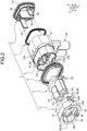
- the connector 1 includes the housing 2, an inner housing 3, the front holder 4, a rear cover 5 serving as a restriction member, and packings 6 and 7.
- a connection counterpart side in the axial direction X may be referred to as a front side and an opposite side in the axial direction X may be referred to as a rear side.
- the housing 2 is a member that houses therein terminals T along the axial direction X.
- the housing 2 of the present embodiment houses and holds the terminals T along the axial direction X via the inner housing 3 provided in the inside.
- the terminal T is a metal fitting made up of metallic material having conductivity.
- the terminal T is a female terminal that is electrically connected to a male counterpart terminal, for example.
- the terminal T is electrically connected to a terminal of the wiring material W.
- a plurality of terminals T are provided, and in this case, two are provided.
- the housing 2 includes a body portion 21 and a wiring-material insertion portion 22 and these are integrally formed by resin material having insulating properties.
- the body portion 21 is formed in a substantially long cylindrical shape for which a central axis line lies along the axial direction X.
- the body portion 21 is formed in an outer shape for which an end portion of the front side in the axial direction X can be fitted in a fitting hole of a connection counterpart.
- the body portion 21 houses the inner housing 3 and the like in an inner space portion 21a in the inside.
- both end portions in the axial direction X are open and constitute respective openings 21b and 21c.
- the opening 21b is an opening formed at the front side end portion in the axial direction X of the body portion 21.
- the front side end portion of the body portion 21 is the end portion on the side to which the front holder 4 is attached, and is the end portion on the side that is fitted in the fitting hole of the connection counterpart.
- the opening 21b exposes the inner housing 3 in the inner space portion 21a toward the front side in the axial direction X externally.
- the opening 21c is an opening formed at the rear side end portion in the axial direction X of the body portion 21.
- the rear side end portion of the body portion 21 is the end portion on the opposite side to the front holder 4 side in the axial direction X (end portion on the opposite side to the side to which the front holder 4 is attached).
- the opening 21c is an opening formed to pull out a die for molding the housing 2 along the axial direction X and is closed by the rear cover 5 described later.
- a partition wall portion 21d (see also FIG. 6 , for example) is formed in the inner space portion 21a and a flange portion 21e is formed on the outer circumferential surface.
- the partition wall portion 21d is a wall portion that sandwiches and holds the inner housing 3 between the front holder 4 and the partition wall portion 21d.
- the flange portion 21e is an annular projecting portion that sandwiches and holds the packing 6 between the front holder 4 and the flange portion 21e.
- the packing 6 is a water stop member that is annularly formed and is attached on the outer circumferential surface of the body portion 21.
- the packing 6 is, in a state where the connector 1 is fitted in the fitting hole of the connection counterpart, interposed between the outer circumferential surface of the body portion 21 and the wall surface of the fitting hole and comes into contact with the foregoing, thereby stopping water and ensuring sealing.
- the wiring-material insertion portion 22 is a portion through which the wiring materials W are inserted.
- the wiring-material insertion portion 22 is formed so as to project toward one side along the height direction Z from a vicinity of the rear side end portion in the axial direction X of the body portion 21.
- the wiring-material insertion portion 22 is formed in a tubular shape, and the wiring materials W are inserted along the height direction Z via the inside. That is, the housing 2 holds the terminals T along the axial direction X and also, along the height direction Z orthogonal to the axial direction X, the wiring materials W are inserted. In this case, two wiring materials W are inserted through the wiring-material insertion portion 22.
- the wiring materials W inserted to the inner space portion 21a via the wiring-material insertion portion 22 are electrically connected to respective terminals T held in the inner housing 3 via relay terminals, a relay bus bar, or the like, for example.
- the inner housing 3 is a member formed separate from the housing 2, and is a member that is provided in the inner space portion 21a of the housing 2 and that houses and holds the terminals T along the axial direction X.
- the inner housing 3 is, in the inner space portion 21a, held between the housing 2 and the front holder 4 in the axial direction X.
- the inner housing 3 includes tubular body portions 31 and a base portion 32 and these are integrally formed by resin material having insulating properties.
- the tubular body portion 31 is formed in a substantially cylindrical shape for which a central axis line lies along the axial direction X.
- the tubular body portion 31 houses and holds the terminal T along the axial direction X in a housing space portion 31a inside (see FIG. 4 , for example).
- the housing space portion 31a is a space portion constituting a terminal insertion chamber (cavity) to which the terminal T is inserted along the axial direction X.
- both end portions in the axial direction X are open and constitute respective openings 31b and 31c.
- the opening 31b is an opening formed at the rear side end portion in the axial direction X of the tubular body portion 31.
- the terminal T is inserted to the housing space portion 31a from the opening 31b and the terminal T is held in the housing space portion 31a.
- the tubular body portion 31 latches the terminal T at a normal position in the housing space portion 31a by a lance or the like that is formed facing the housing space portion 31a.
- the opening 31c is an opening formed at the front side end portion in the axial direction X of the tubular body portion 31.
- the counterpart terminal is inserted from the opening 31c and is connected to the terminal T in the housing space portion 31a.
- the tubular body portions 31 the number of which corresponds to the number of terminals T are provided, and in this case, two are provided.
- the two tubular body portions 31 are positioned in juxtaposition along the width direction Y and are coupled by the base portion 32.
- the base portion 32 is a portion that couples the two tubular body portions 31, and couples the rear side end portions in the axial direction X of the two tubular body portions 31.
- the base portion 32 is, in the inner housing 3, also a portion that is sandwiched and held between the partition wall portion 21d of the housing 2 and the front holder 4 (see also FIG. 6 , for example).
- a space portion is formed so as to face the opening 31b of each tubular body portion 31 and be continuous with the housing space portion 31a.
- the inner housing 3 is, in the inner space portion 21a, positioned such that the tubular body portion 31 is on the front side in the axial direction X and such that the base portion 32 is on the rear side in the axial direction X. In the inner housing 3, with this positional relation, the tubular body portion 31 is exposed externally via the opening 21b and the base portion 32 is held between the partition wall portion 21d of the housing 2 and the front holder 4 (see also FIG. 6 , for example).
- the front holder 4 is a member formed separate from the housing 2, and is a member that holds the inner housing 3 and the packing 6 between the housing 2 and the front holder 4.
- the front holder 4 in the present embodiment is assembled to the front side end portion in the axial direction X of the body portion 21 of the housing 2.
- the front holder 4 holds the terminals T between the housing 2 and the front holder 4 via the inner housing 3 in the axial direction X.
- the front holder 4 includes an outer barrel portion 41, an inner barrel portion 42, and a pair of end wall portions 43 and 44, and these are integrally formed by resin material having insulating properties.
- the outer barrel portion 41 and the inner barrel portion 42 are formed in a substantially long cylindrical shape for which a central axis line lies along the axial direction X.
- the outer barrel portion 41 is positioned on the outside of the inner barrel portion 42, and in other words, the inner barrel portion 42 is positioned on the inner side of the outer barrel portion 41.
- the outer barrel portion 41 is formed so as to have an inner diameter that can tightly adhere to the outer circumferential surface of the front side end portion in the axial direction X of the body portion 21.
- the outer barrel portion 41 is formed in an outer shape that can be fitted in the fitting hole of the connection counterpart.
- the inner barrel portion 42 is formed so as to have an outer diameter that can tightly adhere to the inner circumferential surface of the front side end portion in the axial direction X of the body portion 21.
- both end portions in the axial direction X are open.
- the end wall portion 43 is formed in a substantially long annular plate shape for which a central axis line lies along the axial direction X, and connects the front side end portion in the axial direction X of the outer barrel portion 41 and the front side end portion in the axial direction X of the inner barrel portion 42.
- the end wall portion 43 is connected to the outer barrel portion 41 on the outer diameter side and is connected to the inner barrel portion 42 on the inner diameter side.
- the end wall portion 44 is formed in a substantially long disk shape for which a central axis line lies along the axial direction X, and is provided in the opening formed at the rear side end portion in the axial direction X of the inner barrel portion 42.
- the end wall portion 44 is connected to the inner barrel portion 42 on the outer diameter side.
- insertion holes 44a are formed in the end wall portion 44.
- the insertion hole 44a is, in the end wall portion 44, a through-hole through which the tubular body portion 31 of the inner housing 3 is inserted along the axial direction X.
- the insertion hole 44a is formed in a substantially circular shape.
- the insertion holes 44a the number of which corresponds to the number of tubular body portions 31 are provided, and in this case, two are provided.
- the two insertion holes 44a are positioned in juxtaposition along the width direction Y.
- the front holder 4 is assembled to the housing 2 in the positional relation in which the front side end portion in the axial direction X of the body portion 21 is inserted between the outer barrel portion 41 and the inner barrel portion 42 and in which each of the tubular body portions 31 is inserted to the respective insertion holes 44a.
- the front holder 4, in a state of being assembled to the housing 2, holds the inner housing 3 between the partition wall portion 21d of the housing 2 and the end wall portion 44 and holds the packing 6 between the flange portion 21e of the housing 2 and the rear side end portion in the axial direction X of the outer barrel portion 41 (see also FIG. 6 , for example).
- the latch mechanism 8 includes latch claw portions 81 and latch arm portions 82 that are latched by the latch claw portions 81.
- One of the housing 2 and the front holder 4 has the latch claw portions 81 and the other of the housing 2 and the front holder 4 has the latch arm portions 82.
- the housing 2 has the latch claw portions 81 and the front holder 4 has the latch arm portions 82.
- the latch claw portion 81 is a protrusion to latch the housing 2 and the front holder 4 and is a portion that the latch arm portion 82 is latched.
- the latch claw portions 81 are, in the body portion 21 of the housing 2, formed on the inner wall surface facing the inner space portion 21a (see also FIG. 5 , for example).
- the latch claw portions 81 are provided one each, a total of two, on the inner wall surface on both sides in the width direction Y of the body portion 21.
- the two latch claw portions 81 are positioned facing each other along the width direction Y.
- Each latch claw portion 81 is formed in a claw shape protruding on the inner side (the inner space portion 21a side) along the width direction Y from each inner wall surface of the body portion 21 (see FIG.
- Each latch claw portion 81 has an inclined surface 81a formed on the front side end portion thereof in the axial direction X.
- the inclined surface 81a constitutes a guide surface for guiding the distal end portion of the latch arm portion 82 along the axial direction X.
- the latch arm portion 82 extends along the axial direction X and is, in a state where the housing 2 and the front holder 4 are assembled, a portion to be latched to the latch claw portion 81.
- the latch arm portion 82 is formed on the end wall portion 44 of the front holder 4.
- the latch arm portions 82 are provided one each, a total of two, on both sides in the width direction Y of the insertion hole 44a.
- the two latch arm portions 82 are positioned facing each other across the insertion hole 44a along the width direction Y.
- the latch arm portions 82 are positioned so as to face the respective latch claw portions 81 along the axial direction X.
- Each latch arm portion 82 is formed so as to project in an arm shape toward the rear side along the axial direction X from the end wall portion 44. That is, in each latch arm portion 82, the base portion that is the front side end portion in the axial direction X is fixed to and supported on the end wall portion 44 and the distal end portion that is the rear side end portion in the axial direction X is a free end. As a result, each latch arm portion 82 is supported in a cantilever form that is elastically deformable along the width direction Y with respect to the end wall portion 44.
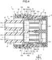
- each latch arm portion 82 is formed as a hook portion in a substantially U-shaped form that can be latched to the latch claw portion 81, and a latching surface 82a is formed at the distal end portion (see FIG. 4 and FIG. 5 , for example). More specifically, each latch arm portion 82 is formed in a substantially U-shaped form by a pair of arm portions 82b and a beam portion 82c.
- the pair of arm portions 82b are portions extending along the axial direction X and positioned at a distance along the height direction Z.
- the beam portion 82c is a portion that connects distal end portions of the pair of arm portions 82b, and the surface on the front side in the axial direction X constitutes the above-described latching surface 82a.
- Each latch arm portion 82 moves to the latching position indicated in FIG. 4 and FIG. 5 , with the operation of assembling the front holder 4 to the housing 2 along the axial direction X, as the beam portion 82c (distal end portion) is guided by the inclined surface 81a and climbs over the latch claw portion 81 with the entire latch arm portion 82 bending in the width direction Y. As a result, in each latch arm portion 82, the latching surface 82a is latched to the latch claw portion 81.
- the front holder 4 is, in a state of being assembled to the housing 2 in the above-described positional relation, latched to the housing 2.
- the rear cover 5 is a member formed separate from the housing 2, is assembled to the opening 21c of the housing 2 together with the packing 7, and is a member that closes the opening 21c.
- the rear cover 5 of the present embodiment is assembled to the housing 2 separately from the front holder 4 and is also used as a restriction member that restricts excessive deforming of the latch arm portion 82.
- the rear cover 5 includes a plate-like portion 51, an outer-peripheral wall portion 52, insulation plates 53, and restriction pieces 54 and these are integrally formed by resin material having insulating properties.
- the plate-like portion 51 is a main portion that closes the opening 21c.
- the plate-like portion 51 is formed in a substantially long disk shape for which a central axis line lies along the axial direction X.
- the outer-peripheral wall portion 52 is a substantially long annular frame-like wall portion formed around the central axis along the axial direction X.
- the outer-peripheral wall portion 52 is provided to stand on the surface on the front side in the axial direction X of the plate-like portion 51.
- the outer-peripheral wall portion 52 is formed at a position offset from the edge of the plate-like portion 51 along the edge.
- the packing 7 is attached on the outer circumferential surface.
- the packing 7 is annularly formed and is a water stop member that is attached on the outer circumferential surface of the outer-peripheral wall portion 52 of the rear cover 5.
- the packing 7 is, in a state where the rear cover 5 is assembled to the opening 21c, interposed between the outer circumferential surface of the outer-peripheral wall portion 52 and the wall surface of the opening 21c and comes into contact with the foregoing, thereby stopping water and ensuring sealing.
- the insulation plate 53 is a wall portion provided to stand on the surface on the front side in the axial direction X of the plate-like portion 51.
- the insulation plate 53 is formed in a substantially rectangular plate-like shape for which the width direction Y is the thickness direction, and extends along the axial direction X and the height direction Z.
- Each insulation plate 53 is, in a state where the rear cover 5 is assembled to the opening 21c, interposed between the two terminals T, and relay terminals, a bus bar, and the like that are connected to the respective terminals T and insulates them mutually.
- the restriction piece 54 of the present embodiment is, in a state where the rear cover 5 is assembled to the housing 2, a portion located adjacent to the latch arm portion 82 that is in a state of being latched to the latch claw portion 81, as illustrated in FIG. 4 and FIG. 6 .
- the restriction piece 54 restricts the displacement of the latch arm portion 82 toward the latch release side.
- the restriction piece 54 is formed as a plate-like wall portion provided to stand on the surface on the front side in the axial direction X of the plate-like portion 51.
- the restriction piece 54 is formed in a substantially rectangular plate-like shape for which the width direction Y is the thickness direction, and extends along the axial direction X and the height direction Z.
- the restriction piece 54 is a belt-like plate piece formed so as to project toward the front side in the axial direction X from the surface on the front side in the axial direction X of the plate-like portion 51.
- the restriction pieces 54, on the surface on the front side in the axial direction X of the plate-like portion 51, are provided one each, a total of two, on both end portions in the width direction Y.
- the two restriction pieces 54 are positioned so as to face each other along the width direction Y.
- the restriction pieces 54 are each, in a state where the rear cover 5 is assembled to the housing 2, formed at a position facing, along the width direction Y, a portion (the beam portion 82c) in the vicinity of the latching surface 82a of the corresponding latch arm portion 82 on the inner side (the inner space portion 21a side) in the width direction Y of the respective latch arm portions 82.
- each restriction piece 54 is formed so as to project along the axial direction X from the outer-peripheral wall portion 52.
- each latch arm portion 82 the base portion that is the rear side end portion in the axial direction X is fixed to and supported on the outer-peripheral wall portion 52, and the distal end portion that is the front side end portion in the axial direction X is located adjacent to the latch claw portion 81 and the latch arm portion 82 in the width direction Y.
- the rear cover 5 is assembled to the opening 21c of the housing 2 after the front holder 4 is assembled to the housing 2.
- each restriction piece 54 is located adjacent to the latch arm portion 82 that is in a state of being latched to the latch claw portion 81 on the inner side in the width direction Y of the latch arm portion 82.
- This configuration enables the rear cover 5 to function as a restriction member that restricts excessive deforming of the latch arm portion 82.
- the connector 1 further includes a fixing structure that fixes the rear cover 5 and the housing 2, in a state where the rear cover 5 is assembled to the opening 21c.
- the fixing structure can use various known locking structures, fastening structures, press-fit structures, or the like, for example.
- the foregoing connector 1 and the wire harness WH allow, with the end portion on the front holder 4 side of the housing 2 fitting in and connecting via the connector to the fitting hole of the connection counterpart, the terminals T and the counterpart terminals to be electrically connected, so as to form an electrical connection region between the two.
- the wire harness WH allows the wiring materials W and the connection counterpart to be electrically connected via the connector 1.
- the housing 2 and the front holder 4 are assembled to each other with the latch claw portion 81 and the latch arm portion 82 being latched together.
- the rear cover 5 can, in a state of being assembled to the housing 2, restrict by the restriction piece 54, the displacement of the latch arm portion 82 that is in a state of being latched to the latch claw portion 81 toward the latch release side, that is, the displacement toward the width direction Y side, as illustrated in FIG. 4 and FIG. 6 .
- the connector 1 can properly maintain the state where the latch arm portion 82 and the latch claw portion 81 are latched together. Consequently, the connector 1 can maintain the state where the housing 2 and the front holder 4 that are the components are properly assembled. As a result, the connector 1 and the wire harness WH can assemble the components properly.
- the rear cover 5 that is a component separate from the housing 2 and the front holder 4, and closes the opening 21c can also be used as a restriction member on which the restriction pieces 54 are provided.
- the connector 1 and the wire harness WH can assemble the components properly as in the foregoing while restraining the number of components from increasing.
- the foregoing connector 1 and the wire harness WH have a configuration in which the restriction pieces 54 are formed so as to project from the outer-peripheral wall portion 52 of the rear cover 5, the base portion of the restriction piece 54 can be reinforced by the outer-peripheral wall portion 52.
- the connector 1 or the wire harness WH can reliably restrict the displacement of the latch arm portion 82 toward the latch release side by the reinforced restriction piece 54, the components can be assembled more properly.
- the restriction member may be configured as a member separate from the rear cover 5.
- the restriction member may be, instead of the rear cover 5, what is called a rear holder that holds the terminals of the wiring materials W, or may be a dedicated member separate from those.
- the housing 2 houses and holds the terminals T along the axial direction X via the inner housing 3 that is housed in the inner space portion 21a
- the embodiments are not limited thereto.
- the connector 1 may be in a configuration in which the inner housing 3 is not included.
- the connector 1 has a configuration in which the housing 2 includes the latch claw portions 81 and the front holder 4 includes the latch arm portions 82. Inversely, however, the connector 1 may have a configuration in which the housing 2 includes the latch arm portions and the front holder 4 includes the latch claw portions.
- each restriction piece 54 is formed so as to project along the axial direction X from the outer-peripheral wall portion 52, the embodiments are not limited thereto.
- the rear cover 5 may be in a configuration in which the outer-peripheral wall portion 52 is not included.
- the connector 1 may constitute a connection mechanism for wiring-material-to-wiring-material connection capable of electrically connecting the wiring materials.
- the terminal T is a female terminal
- the terminal T may be a male terminal that is electrically connected to a female counterpart terminal.
- the connector may have, in the relation among the housing, the front holder, and the rear cover, a configuration in which the front holder functions as the above-described restriction member. That is, in this case, the connector according to the reference example includes a housing that houses therein terminals along the axial direction, a front holder that is assembled to an end portion in the axial direction of the housing and holds the terminals between the housing and the front holder in the axial direction, and a rear cover that is assembled to an opening formed at an end portion on the opposite side to the front holder side of the axial direction in the housing and closes the opening.
- One of the housing or the rear cover has a latch claw portion that latches the housing and the rear cover
- the other of the housing or the rear cover has a latch arm portion that extends along the axial direction and is latched to the latch claw portion in a state where the housing and the rear cover are assembled.
- the front holder in a state of being assembled to the housing, functions as a restriction member, by having a restriction piece that is located adjacent to the latch arm portion in a state of being latched to the latch claw portion and restricts the displacement of the latch arm portion toward the latch release side.
- the connector in the reference example also makes it possible to assemble the components properly.
- the connector and the wire harness include the housing, the front holder, and the restriction member.
- the housing and the front holder are assembled to each other when the latch claw portion and the latch arm portion are latched together.
- the restriction member can, in a state of being assembled to the housing, restrict by the restriction piece the displacement of the latch arm portion that is in a state of being latched to the latch claw portion toward the latch release side.
Landscapes
- Engineering & Computer Science (AREA)
- Mechanical Engineering (AREA)
- Connector Housings Or Holding Contact Members (AREA)
- Details Of Connecting Devices For Male And Female Coupling (AREA)
Claims (3)
- Ein Verbinder (1), aufweisend:ein Gehäuse (2), das so konfiguriert ist, dass es darin einen Anschluss (T) entlang einer axialen Richtung (X) aufnimmt;einen vorderen Halter (4), der an einem Endabschnitt in der axialen Richtung (X) des Gehäuses (2) montiert ist, wobei der vordere Halter (4) so konfiguriert ist, dass er den Anschluss (T) zwischen dem Gehäuse (2) und dem vorderen Halter (4) in der axialen Richtung (X) hält; undein Begrenzungselement (5), das an dem Gehäuse (2) montiert ist, wobeidas Gehäuse (2) oder der vordere Halter (4) einen Verriegelungsklauenabschnitt (81) aufweist, der zum Verriegeln des Gehäuses (2) und des vorderen Halters (4) konfiguriert ist,das jeweils andere Element, d.h. das Gehäuse (2) oder der vordere Halter (4), einen Verriegelungsarmabschnitt (82) aufweist, der sich entlang der axialen Richtung (X) erstreckt, wobei der Verriegelungsarmabschnitt (82) so konfiguriert ist, dass er in einem Zustand, in dem das Gehäuse (2) und der vordere Halter (4) zusammengebaut sind, mit dem Verriegelungsklauenabschnitt (81) verriegelt wird, und das Begrenzungselement (5) Folgendes aufweist, in einem Zustand, in dem das Gehäuse (2) und der vordere Halter (4) zusammengebaut sind, ein Begrenzungsteil (54) enthält, das neben dem Verriegelungsarmabschnitt (82) angeordnet ist, der sich in einem Zustand befindet, in dem er mit dem Verriegelungsklauenabschnitt (81) verriegelt ist, wobei das Begrenzungsteil (54) so konfiguriert ist, dass es die Verschiebung des Verriegelungsarmabschnitts (82) in Richtung einer Verriegelungsfreigabeseite begrenzt,dadurch gekennzeichnet, dassdas Gehäuse (2) eine Öffnung (21c) hat, die an einem Endabschnitt auf der der vorderen Halterseite (4) in der axialen Richtung (X) gegenüberliegenden Seite ausgebildet ist, und einen Verdrahtungsmaterial-Einführungsabschnitt (22) aufweist, der so ausgebildet ist, dass er entlang einer Höhenrichtung (Z) orthogonal zu der axialen Richtung (X) von dem Endabschnitt auf der gegenüberliegenden Seite zu der vorderen Halterseite (4) in der axialen Richtung (X) zu einer Seite hin vorsteht, und ein Abschnitt ist, durch den ein Verdrahtungsmaterial (W), das elektrisch mit dem Anschluss (T) verbunden ist, konfiguriert ist entlang der Höhenrichtung (Z) eingeführt zu werden, und das Begrenzungselement (5) eine hintere Abdeckung (5) ist, die getrennt von dem vorderen Halter (4) an der Öffnung (21c) montiert wird und die Öffnung (21c) verschließt.
- Der Verbinder (1) nach Anspruch 1, wobeidas Begrenzungselement (5) einen Außenumfangswandabschnitt (52) aufweist, der um eine Achse entlang der axialen Richtung (X) ausgebildet ist, unddas Beschränkungsstück (54) so ausgebildet ist, dass es entlang der axialen Richtung (X) von dem Außenumfangswandabschnitt (52) vorsteht.
- Ein Kabelbaum (WH), umfassend:das Verdrahtungsmaterial (W) mit Leitfähigkeit; undeinen Verbinder (1) nach Anspruch 1, der elektrisch mit dem Verdrahtungsmaterial (W) verbunden ist.
Applications Claiming Priority (1)
| Application Number | Priority Date | Filing Date | Title |
|---|---|---|---|
| JP2019098171A JP6999246B2 (ja) | 2019-05-27 | 2019-05-27 | コネクタ、及び、ワイヤハーネス |
Publications (2)
| Publication Number | Publication Date |
|---|---|
| EP3745540A1 EP3745540A1 (de) | 2020-12-02 |
| EP3745540B1 true EP3745540B1 (de) | 2024-10-23 |
Family
ID=70802660
Family Applications (1)
| Application Number | Title | Priority Date | Filing Date |
|---|---|---|---|
| EP20175763.0A Active EP3745540B1 (de) | 2019-05-27 | 2020-05-20 | Verbinder und kabelbaum |
Country Status (4)
| Country | Link |
|---|---|
| US (1) | US11355887B2 (de) |
| EP (1) | EP3745540B1 (de) |
| JP (1) | JP6999246B2 (de) |
| CN (1) | CN112003057B (de) |
Families Citing this family (4)
| Publication number | Priority date | Publication date | Assignee | Title |
|---|---|---|---|---|
| JP7027011B2 (ja) * | 2019-06-25 | 2022-03-01 | 矢崎総業株式会社 | コネクタ |
| JP7655038B2 (ja) * | 2021-03-26 | 2025-04-02 | 住友電装株式会社 | コネクタ |
| JP7401504B2 (ja) | 2021-10-19 | 2023-12-19 | 矢崎総業株式会社 | コネクタ |
| JP7630772B2 (ja) * | 2021-11-24 | 2025-02-18 | 株式会社オートネットワーク技術研究所 | コネクタ |
Citations (1)
| Publication number | Priority date | Publication date | Assignee | Title |
|---|---|---|---|---|
| US5697806A (en) * | 1995-07-06 | 1997-12-16 | The Whitaker Corporation | Stackable electrical connector |
Family Cites Families (19)
| Publication number | Priority date | Publication date | Assignee | Title |
|---|---|---|---|---|
| US3467942A (en) * | 1965-03-10 | 1969-09-16 | Amp Inc | Housing member |
| US3671921A (en) * | 1970-10-28 | 1972-06-20 | Amp Inc | Multi-contact electrical connector |
| JPS5749913Y2 (de) * | 1979-09-05 | 1982-11-01 | ||
| US4657331A (en) * | 1985-05-21 | 1987-04-14 | Amp Incorporated | Strain relief for electrical connector assemblies |
| US5104253A (en) * | 1990-06-06 | 1992-04-14 | Chrysler Corporation | Cable assembly, lock therefor |
| JP2582750Y2 (ja) * | 1992-10-06 | 1998-10-08 | 住友電装株式会社 | コネクタ用カバー |
| US6140722A (en) * | 1999-05-24 | 2000-10-31 | Unit Parts Company | Alternator system |
| JP3672229B2 (ja) * | 2000-02-23 | 2005-07-20 | 矢崎総業株式会社 | ホルダ抜け防止コネクタ |
| US7021959B2 (en) * | 2002-11-22 | 2006-04-04 | Sumitomo Wiring Systems, Ltd. | Wire cover with two longitudinal halves connectable around electric wires |
| JP4839989B2 (ja) * | 2006-07-04 | 2011-12-21 | 住友電装株式会社 | コネクタ |
| JP2009181722A (ja) | 2008-01-29 | 2009-08-13 | Sumitomo Wiring Syst Ltd | コネクタ |
| US7892045B2 (en) * | 2008-10-23 | 2011-02-22 | Tyco Electronics Corporation | Connector having interlocking components |
| JP5923898B2 (ja) * | 2011-08-30 | 2016-05-25 | ブラザー工業株式会社 | 現像装置 |
| JP6116821B2 (ja) * | 2012-06-08 | 2017-04-19 | 矢崎総業株式会社 | コネクタ |
| JP5912966B2 (ja) | 2012-07-26 | 2016-04-27 | 矢崎総業株式会社 | コネクタ |
| JP2014154359A (ja) * | 2013-02-08 | 2014-08-25 | Yazaki Corp | コネクタ |
| US10573988B2 (en) * | 2017-08-01 | 2020-02-25 | Delphi Technologies, Llc | Cable assembly with strain relief |
| US10249976B1 (en) * | 2018-04-10 | 2019-04-02 | Sumitomo Wiring Systems, Ltd. | Connector housing assembly with a dress cover having finger feature and ribs |
| JP6735313B2 (ja) * | 2018-05-22 | 2020-08-05 | 矢崎総業株式会社 | 閉塞体保持構造及びコネクタ付き電線 |
-
2019
- 2019-05-27 JP JP2019098171A patent/JP6999246B2/ja active Active
-
2020
- 2020-05-20 US US16/879,731 patent/US11355887B2/en active Active
- 2020-05-20 EP EP20175763.0A patent/EP3745540B1/de active Active
- 2020-05-26 CN CN202010455878.XA patent/CN112003057B/zh active Active
Patent Citations (1)
| Publication number | Priority date | Publication date | Assignee | Title |
|---|---|---|---|---|
| US5697806A (en) * | 1995-07-06 | 1997-12-16 | The Whitaker Corporation | Stackable electrical connector |
Also Published As
| Publication number | Publication date |
|---|---|
| US20200381861A1 (en) | 2020-12-03 |
| CN112003057A (zh) | 2020-11-27 |
| CN112003057B (zh) | 2022-05-17 |
| US11355887B2 (en) | 2022-06-07 |
| JP2020194645A (ja) | 2020-12-03 |
| JP6999246B2 (ja) | 2022-01-18 |
| EP3745540A1 (de) | 2020-12-02 |
Similar Documents
| Publication | Publication Date | Title |
|---|---|---|
| EP3745540B1 (de) | Verbinder und kabelbaum | |
| JP5033651B2 (ja) | ワイヤハーネス及びワイヤハーネス組立方法 | |
| EP3835135B1 (de) | Elektrischer anschlusskasten und kabelstrang | |
| CN113904162A (zh) | 连接器 | |
| US12573791B2 (en) | Connector | |
| JP2010225488A (ja) | コネクタ | |
| US11464122B2 (en) | Lock structure, electrical connection box, and wire harness | |
| US20250329955A1 (en) | Connector | |
| JP3998922B2 (ja) | コネクタ | |
| CN114792908B (zh) | 线束 | |
| US20240075888A1 (en) | Wire harness | |
| EP3648260B1 (de) | Elektrischer verbinder und kabelbaum | |
| JP2014060073A (ja) | コネクタ | |
| US12519263B2 (en) | Device connector | |
| JP7715763B2 (ja) | コネクタ、コネクタ製造方法及びワイヤハーネス | |
| CN119366069A (zh) | 连接器组件、第1连接器、第2连接器 | |
| JP2003045556A (ja) | カバー付コネクタ | |
| JP2019033001A (ja) | 電子ユニットの取付構造 | |
| US12392669B2 (en) | Temperature sensor and wire harness | |
| US12344173B2 (en) | Sheath assembly and wire harness | |
| US20260018833A1 (en) | Shield bracket and wire harness | |
| JP7832238B2 (ja) | コネクタ | |
| US20250289379A1 (en) | Wire harness wiring structure and wire harness | |
| US12482984B2 (en) | Connector assembly, wire harness, and connector cover | |
| JP7146836B2 (ja) | プロテクタ、及びプロテクタへのコネクタ固定構造 |
Legal Events
| Date | Code | Title | Description |
|---|---|---|---|
| PUAI | Public reference made under article 153(3) epc to a published international application that has entered the european phase |
Free format text: ORIGINAL CODE: 0009012 |
|
| STAA | Information on the status of an ep patent application or granted ep patent |
Free format text: STATUS: REQUEST FOR EXAMINATION WAS MADE |
|
| 17P | Request for examination filed |
Effective date: 20200520 |
|
| AK | Designated contracting states |
Kind code of ref document: A1 Designated state(s): AL AT BE BG CH CY CZ DE DK EE ES FI FR GB GR HR HU IE IS IT LI LT LU LV MC MK MT NL NO PL PT RO RS SE SI SK SM TR |
|
| AX | Request for extension of the european patent |
Extension state: BA ME |
|
| STAA | Information on the status of an ep patent application or granted ep patent |
Free format text: STATUS: EXAMINATION IS IN PROGRESS |
|
| 17Q | First examination report despatched |
Effective date: 20210804 |
|
| RAP3 | Party data changed (applicant data changed or rights of an application transferred) |
Owner name: YAZAKI CORPORATION |
|
| GRAP | Despatch of communication of intention to grant a patent |
Free format text: ORIGINAL CODE: EPIDOSNIGR1 |
|
| STAA | Information on the status of an ep patent application or granted ep patent |
Free format text: STATUS: GRANT OF PATENT IS INTENDED |
|
| RIC1 | Information provided on ipc code assigned before grant |
Ipc: H01R 103/00 20060101ALN20240726BHEP Ipc: H01R 13/52 20060101ALN20240726BHEP Ipc: H01R 13/506 20060101ALI20240726BHEP Ipc: H01R 13/436 20060101AFI20240726BHEP |
|
| RIC1 | Information provided on ipc code assigned before grant |
Ipc: H01R 103/00 20060101ALN20240803BHEP Ipc: H01R 13/52 20060101ALN20240803BHEP Ipc: H01R 13/506 20060101ALI20240803BHEP Ipc: H01R 13/436 20060101AFI20240803BHEP |
|
| GRAS | Grant fee paid |
Free format text: ORIGINAL CODE: EPIDOSNIGR3 |
|
| GRAA | (expected) grant |
Free format text: ORIGINAL CODE: 0009210 |
|
| STAA | Information on the status of an ep patent application or granted ep patent |
Free format text: STATUS: THE PATENT HAS BEEN GRANTED |
|
| INTG | Intention to grant announced |
Effective date: 20240828 |
|
| AK | Designated contracting states |
Kind code of ref document: B1 Designated state(s): AL AT BE BG CH CY CZ DE DK EE ES FI FR GB GR HR HU IE IS IT LI LT LU LV MC MK MT NL NO PL PT RO RS SE SI SK SM TR |
|
| REG | Reference to a national code |
Ref country code: GB Ref legal event code: FG4D |
|
| REG | Reference to a national code |
Ref country code: CH Ref legal event code: EP |
|
| REG | Reference to a national code |
Ref country code: DE Ref legal event code: R096 Ref document number: 602020039787 Country of ref document: DE |
|
| REG | Reference to a national code |
Ref country code: IE Ref legal event code: FG4D |
|
| REG | Reference to a national code |
Ref country code: LT Ref legal event code: MG9D |
|
| REG | Reference to a national code |
Ref country code: NL Ref legal event code: MP Effective date: 20241023 |
|
| REG | Reference to a national code |
Ref country code: AT Ref legal event code: MK05 Ref document number: 1735622 Country of ref document: AT Kind code of ref document: T Effective date: 20241023 |
|
| PG25 | Lapsed in a contracting state [announced via postgrant information from national office to epo] |
Ref country code: NL Free format text: LAPSE BECAUSE OF FAILURE TO SUBMIT A TRANSLATION OF THE DESCRIPTION OR TO PAY THE FEE WITHIN THE PRESCRIBED TIME-LIMIT Effective date: 20241023 |
|
| PG25 | Lapsed in a contracting state [announced via postgrant information from national office to epo] |
Ref country code: NL Free format text: LAPSE BECAUSE OF FAILURE TO SUBMIT A TRANSLATION OF THE DESCRIPTION OR TO PAY THE FEE WITHIN THE PRESCRIBED TIME-LIMIT Effective date: 20241023 |
|
| PG25 | Lapsed in a contracting state [announced via postgrant information from national office to epo] |
Ref country code: IS Free format text: LAPSE BECAUSE OF FAILURE TO SUBMIT A TRANSLATION OF THE DESCRIPTION OR TO PAY THE FEE WITHIN THE PRESCRIBED TIME-LIMIT Effective date: 20250223 Ref country code: HR Free format text: LAPSE BECAUSE OF FAILURE TO SUBMIT A TRANSLATION OF THE DESCRIPTION OR TO PAY THE FEE WITHIN THE PRESCRIBED TIME-LIMIT Effective date: 20241023 Ref country code: PT Free format text: LAPSE BECAUSE OF FAILURE TO SUBMIT A TRANSLATION OF THE DESCRIPTION OR TO PAY THE FEE WITHIN THE PRESCRIBED TIME-LIMIT Effective date: 20250224 |
|
| PG25 | Lapsed in a contracting state [announced via postgrant information from national office to epo] |
Ref country code: FI Free format text: LAPSE BECAUSE OF FAILURE TO SUBMIT A TRANSLATION OF THE DESCRIPTION OR TO PAY THE FEE WITHIN THE PRESCRIBED TIME-LIMIT Effective date: 20241023 |
|
| PG25 | Lapsed in a contracting state [announced via postgrant information from national office to epo] |
Ref country code: BG Free format text: LAPSE BECAUSE OF FAILURE TO SUBMIT A TRANSLATION OF THE DESCRIPTION OR TO PAY THE FEE WITHIN THE PRESCRIBED TIME-LIMIT Effective date: 20241023 |
|
| PG25 | Lapsed in a contracting state [announced via postgrant information from national office to epo] |
Ref country code: ES Free format text: LAPSE BECAUSE OF FAILURE TO SUBMIT A TRANSLATION OF THE DESCRIPTION OR TO PAY THE FEE WITHIN THE PRESCRIBED TIME-LIMIT Effective date: 20241023 |
|
| PG25 | Lapsed in a contracting state [announced via postgrant information from national office to epo] |
Ref country code: NO Free format text: LAPSE BECAUSE OF FAILURE TO SUBMIT A TRANSLATION OF THE DESCRIPTION OR TO PAY THE FEE WITHIN THE PRESCRIBED TIME-LIMIT Effective date: 20250123 |
|
| PG25 | Lapsed in a contracting state [announced via postgrant information from national office to epo] |
Ref country code: AT Free format text: LAPSE BECAUSE OF FAILURE TO SUBMIT A TRANSLATION OF THE DESCRIPTION OR TO PAY THE FEE WITHIN THE PRESCRIBED TIME-LIMIT Effective date: 20241023 Ref country code: LV Free format text: LAPSE BECAUSE OF FAILURE TO SUBMIT A TRANSLATION OF THE DESCRIPTION OR TO PAY THE FEE WITHIN THE PRESCRIBED TIME-LIMIT Effective date: 20241023 Ref country code: GR Free format text: LAPSE BECAUSE OF FAILURE TO SUBMIT A TRANSLATION OF THE DESCRIPTION OR TO PAY THE FEE WITHIN THE PRESCRIBED TIME-LIMIT Effective date: 20250124 |
|
| PG25 | Lapsed in a contracting state [announced via postgrant information from national office to epo] |
Ref country code: PL Free format text: LAPSE BECAUSE OF FAILURE TO SUBMIT A TRANSLATION OF THE DESCRIPTION OR TO PAY THE FEE WITHIN THE PRESCRIBED TIME-LIMIT Effective date: 20241023 |
|
| PG25 | Lapsed in a contracting state [announced via postgrant information from national office to epo] |
Ref country code: RS Free format text: LAPSE BECAUSE OF FAILURE TO SUBMIT A TRANSLATION OF THE DESCRIPTION OR TO PAY THE FEE WITHIN THE PRESCRIBED TIME-LIMIT Effective date: 20250123 |
|
| PG25 | Lapsed in a contracting state [announced via postgrant information from national office to epo] |
Ref country code: SM Free format text: LAPSE BECAUSE OF FAILURE TO SUBMIT A TRANSLATION OF THE DESCRIPTION OR TO PAY THE FEE WITHIN THE PRESCRIBED TIME-LIMIT Effective date: 20241023 |
|
| PGFP | Annual fee paid to national office [announced via postgrant information from national office to epo] |
Ref country code: DE Payment date: 20250528 Year of fee payment: 6 |
|
| PG25 | Lapsed in a contracting state [announced via postgrant information from national office to epo] |
Ref country code: DK Free format text: LAPSE BECAUSE OF FAILURE TO SUBMIT A TRANSLATION OF THE DESCRIPTION OR TO PAY THE FEE WITHIN THE PRESCRIBED TIME-LIMIT Effective date: 20241023 |
|
| PG25 | Lapsed in a contracting state [announced via postgrant information from national office to epo] |
Ref country code: EE Free format text: LAPSE BECAUSE OF FAILURE TO SUBMIT A TRANSLATION OF THE DESCRIPTION OR TO PAY THE FEE WITHIN THE PRESCRIBED TIME-LIMIT Effective date: 20241023 |
|
| PG25 | Lapsed in a contracting state [announced via postgrant information from national office to epo] |
Ref country code: RO Free format text: LAPSE BECAUSE OF FAILURE TO SUBMIT A TRANSLATION OF THE DESCRIPTION OR TO PAY THE FEE WITHIN THE PRESCRIBED TIME-LIMIT Effective date: 20241023 |
|
| REG | Reference to a national code |
Ref country code: DE Ref legal event code: R097 Ref document number: 602020039787 Country of ref document: DE |
|
| PG25 | Lapsed in a contracting state [announced via postgrant information from national office to epo] |
Ref country code: SK Free format text: LAPSE BECAUSE OF FAILURE TO SUBMIT A TRANSLATION OF THE DESCRIPTION OR TO PAY THE FEE WITHIN THE PRESCRIBED TIME-LIMIT Effective date: 20241023 |
|
| PG25 | Lapsed in a contracting state [announced via postgrant information from national office to epo] |
Ref country code: CZ Free format text: LAPSE BECAUSE OF FAILURE TO SUBMIT A TRANSLATION OF THE DESCRIPTION OR TO PAY THE FEE WITHIN THE PRESCRIBED TIME-LIMIT Effective date: 20241023 |
|
| PG25 | Lapsed in a contracting state [announced via postgrant information from national office to epo] |
Ref country code: IT Free format text: LAPSE BECAUSE OF FAILURE TO SUBMIT A TRANSLATION OF THE DESCRIPTION OR TO PAY THE FEE WITHIN THE PRESCRIBED TIME-LIMIT Effective date: 20241023 |
|
| PLBE | No opposition filed within time limit |
Free format text: ORIGINAL CODE: 0009261 |
|
| STAA | Information on the status of an ep patent application or granted ep patent |
Free format text: STATUS: NO OPPOSITION FILED WITHIN TIME LIMIT |
|
| PG25 | Lapsed in a contracting state [announced via postgrant information from national office to epo] |
Ref country code: SE Free format text: LAPSE BECAUSE OF FAILURE TO SUBMIT A TRANSLATION OF THE DESCRIPTION OR TO PAY THE FEE WITHIN THE PRESCRIBED TIME-LIMIT Effective date: 20241023 |
|
| 26N | No opposition filed |
Effective date: 20250724 |
|
| REG | Reference to a national code |
Ref country code: CH Ref legal event code: H13 Free format text: ST27 STATUS EVENT CODE: U-0-0-H10-H13 (AS PROVIDED BY THE NATIONAL OFFICE) Effective date: 20251223 |
|
| PG25 | Lapsed in a contracting state [announced via postgrant information from national office to epo] |
Ref country code: LU Free format text: LAPSE BECAUSE OF NON-PAYMENT OF DUE FEES Effective date: 20250520 |
|
| PG25 | Lapsed in a contracting state [announced via postgrant information from national office to epo] |
Ref country code: CH Free format text: LAPSE BECAUSE OF NON-PAYMENT OF DUE FEES Effective date: 20250531 |
|
| GBPC | Gb: european patent ceased through non-payment of renewal fee |
Effective date: 20250520 |
|
| REG | Reference to a national code |
Ref country code: BE Ref legal event code: MM Effective date: 20250531 |
|
| PG25 | Lapsed in a contracting state [announced via postgrant information from national office to epo] |
Ref country code: MC Free format text: LAPSE BECAUSE OF FAILURE TO SUBMIT A TRANSLATION OF THE DESCRIPTION OR TO PAY THE FEE WITHIN THE PRESCRIBED TIME-LIMIT Effective date: 20241023 |
|
| PG25 | Lapsed in a contracting state [announced via postgrant information from national office to epo] |
Ref country code: GB Free format text: LAPSE BECAUSE OF NON-PAYMENT OF DUE FEES Effective date: 20250520 |
|
| PG25 | Lapsed in a contracting state [announced via postgrant information from national office to epo] |
Ref country code: IE Free format text: LAPSE BECAUSE OF NON-PAYMENT OF DUE FEES Effective date: 20250520 |
|
| PG25 | Lapsed in a contracting state [announced via postgrant information from national office to epo] |
Ref country code: BE Free format text: LAPSE BECAUSE OF NON-PAYMENT OF DUE FEES Effective date: 20250531 |
|
| PG25 | Lapsed in a contracting state [announced via postgrant information from national office to epo] |
Ref country code: FR Free format text: LAPSE BECAUSE OF NON-PAYMENT OF DUE FEES Effective date: 20250531 |