EP3745632A1 - Verfahren zur bestimmung eines antennenports und anschlussseitige vorrichtung - Google Patents
Verfahren zur bestimmung eines antennenports und anschlussseitige vorrichtung Download PDFInfo
- Publication number
- EP3745632A1 EP3745632A1 EP19751047.2A EP19751047A EP3745632A1 EP 3745632 A1 EP3745632 A1 EP 3745632A1 EP 19751047 A EP19751047 A EP 19751047A EP 3745632 A1 EP3745632 A1 EP 3745632A1
- Authority
- EP
- European Patent Office
- Prior art keywords
- antenna port
- dmrs
- group
- information
- codeword
- Prior art date
- Legal status (The legal status is an assumption and is not a legal conclusion. Google has not performed a legal analysis and makes no representation as to the accuracy of the status listed.)
- Withdrawn
Links
- 238000000034 method Methods 0.000 title claims abstract description 48
- 230000005540 biological transmission Effects 0.000 claims description 96
- 230000006870 function Effects 0.000 description 17
- 238000010586 diagram Methods 0.000 description 16
- 230000011664 signaling Effects 0.000 description 9
- 238000004590 computer program Methods 0.000 description 7
- 230000007774 longterm Effects 0.000 description 6
- 230000009286 beneficial effect Effects 0.000 description 5
- 230000001427 coherent effect Effects 0.000 description 2
- 238000013507 mapping Methods 0.000 description 2
- 230000003287 optical effect Effects 0.000 description 2
- 230000002093 peripheral effect Effects 0.000 description 2
- 238000001228 spectrum Methods 0.000 description 2
- 238000001514 detection method Methods 0.000 description 1
- 230000000694 effects Effects 0.000 description 1
- 238000005516 engineering process Methods 0.000 description 1
- 238000000802 evaporation-induced self-assembly Methods 0.000 description 1
- 238000005562 fading Methods 0.000 description 1
- 239000011159 matrix material Substances 0.000 description 1
- 230000001360 synchronised effect Effects 0.000 description 1
Images

Classifications
-
- H—ELECTRICITY
- H04—ELECTRIC COMMUNICATION TECHNIQUE
- H04L—TRANSMISSION OF DIGITAL INFORMATION, e.g. TELEGRAPHIC COMMUNICATION
- H04L5/00—Arrangements affording multiple use of the transmission path
- H04L5/003—Arrangements for allocating sub-channels of the transmission path
- H04L5/0053—Allocation of signalling, i.e. of overhead other than pilot signals
-
- H—ELECTRICITY
- H04—ELECTRIC COMMUNICATION TECHNIQUE
- H04B—TRANSMISSION
- H04B17/00—Monitoring; Testing
- H04B17/20—Monitoring; Testing of receivers
- H04B17/27—Monitoring; Testing of receivers for locating or positioning the transmitter
-
- H—ELECTRICITY
- H04—ELECTRIC COMMUNICATION TECHNIQUE
- H04B—TRANSMISSION
- H04B17/00—Monitoring; Testing
- H04B17/10—Monitoring; Testing of transmitters
- H04B17/101—Monitoring; Testing of transmitters for measurement of specific parameters of the transmitter or components thereof
- H04B17/102—Power radiated at antenna
-
- H—ELECTRICITY
- H04—ELECTRIC COMMUNICATION TECHNIQUE
- H04J—MULTIPLEX COMMUNICATION
- H04J13/00—Code division multiplex systems
- H04J13/0007—Code type
- H04J13/004—Orthogonal
-
- H—ELECTRICITY
- H04—ELECTRIC COMMUNICATION TECHNIQUE
- H04L—TRANSMISSION OF DIGITAL INFORMATION, e.g. TELEGRAPHIC COMMUNICATION
- H04L5/00—Arrangements affording multiple use of the transmission path
- H04L5/0091—Signalling for the administration of the divided path, e.g. signalling of configuration information
- H04L5/0094—Indication of how sub-channels of the path are allocated
-
- H—ELECTRICITY
- H04—ELECTRIC COMMUNICATION TECHNIQUE
- H04W—WIRELESS COMMUNICATION NETWORKS
- H04W72/00—Local resource management
- H04W72/04—Wireless resource allocation
- H04W72/044—Wireless resource allocation based on the type of the allocated resource
- H04W72/046—Wireless resource allocation based on the type of the allocated resource the resource being in the space domain, e.g. beams
-
- H—ELECTRICITY
- H04—ELECTRIC COMMUNICATION TECHNIQUE
- H04W—WIRELESS COMMUNICATION NETWORKS
- H04W72/00—Local resource management
- H04W72/20—Control channels or signalling for resource management
- H04W72/23—Control channels or signalling for resource management in the downlink direction of a wireless link, i.e. towards a terminal
-
- H—ELECTRICITY
- H04—ELECTRIC COMMUNICATION TECHNIQUE
- H04B—TRANSMISSION
- H04B7/00—Radio transmission systems, i.e. using radiation field
- H04B7/02—Diversity systems; Multi-antenna system, i.e. transmission or reception using multiple antennas
- H04B7/04—Diversity systems; Multi-antenna system, i.e. transmission or reception using multiple antennas using two or more spaced independent antennas
- H04B7/0413—MIMO systems
- H04B7/0452—Multi-user MIMO systems
-
- H—ELECTRICITY
- H04—ELECTRIC COMMUNICATION TECHNIQUE
- H04L—TRANSMISSION OF DIGITAL INFORMATION, e.g. TELEGRAPHIC COMMUNICATION
- H04L25/00—Baseband systems
- H04L25/02—Details ; arrangements for supplying electrical power along data transmission lines
- H04L25/0202—Channel estimation
- H04L25/0204—Channel estimation of multiple channels
-
- H—ELECTRICITY
- H04—ELECTRIC COMMUNICATION TECHNIQUE
- H04L—TRANSMISSION OF DIGITAL INFORMATION, e.g. TELEGRAPHIC COMMUNICATION
- H04L25/00—Baseband systems
- H04L25/02—Details ; arrangements for supplying electrical power along data transmission lines
- H04L25/0202—Channel estimation
- H04L25/0224—Channel estimation using sounding signals
- H04L25/0228—Channel estimation using sounding signals with direct estimation from sounding signals
-
- H—ELECTRICITY
- H04—ELECTRIC COMMUNICATION TECHNIQUE
- H04L—TRANSMISSION OF DIGITAL INFORMATION, e.g. TELEGRAPHIC COMMUNICATION
- H04L5/00—Arrangements affording multiple use of the transmission path
- H04L5/003—Arrangements for allocating sub-channels of the transmission path
- H04L5/0048—Allocation of pilot signals, i.e. of signals known to the receiver
Definitions
- Embodiments of this application relate to the field of wireless communications, and in particular, to an antenna port determining technology.
- a wireless communications system includes a terminal side device and a network side device that serves the terminal side device.
- the terminal side device and the network side device have protocol layers that are specified in the 3rd generation partnership project (the 3rd partnership project, 3GPP) standard and that include a physical (physical, PHY) layer, a media access control (medium access control, MAC) layer, a radio link control (radio link control, RLC) layer, a packet data convergence (packet data convergence protocol, PDCP) layer, a radio resource control (radio resource control, RRC) layer, and the like.
- Protocol layers except the physical layer, including the MAC layer, the RLC layer, the PDCP layer, the RRC layer, and the like, are collectively referred to as a higher layer.
- the network side device maps, at the physical layer, a demodulation reference signal (demodulation reference signal, DMRS) to at least one antenna port (DMRS antenna port for short), and sends the demodulation reference signal to the terminal side device in the downlink.
- DMRS demodulation reference signal
- the network side device may send downlink control information (downlink control information, DCI) in a specific format to the terminal side device on a physical downlink control channel (physical downlink control channel, PDCCH).
- the downlink control information includes indication information that can be used to determine antenna port numbers of DMRS antenna ports on which the downlink data is scheduled.
- the network side device may further indicate, to the terminal side device by using the downlink control information, at least one piece of quasi-colocation (quasi-co-located, QCL) information used when the downlink data is scheduled. Each piece of QCL information indicates that there is a QCL relationship between a DMRS antenna port and another antenna port.
- the terminal side device may determine the DMRS antenna ports based on the indication information and the QCL information.
- the antenna ports may not be accurately determined.
- a first aspect of embodiments of this application provides an antenna port determining method, where the method is performed by a terminal side device and includes the following content: receiving downlink control information, where the downlink control information includes quasi co-location QCL information and indication information that is used to determine an antenna port number of a first antenna port on which downlink data is scheduled, and the QCL information indicates that there is a quasi-colocation QCL relationship between the first antenna port and a second antenna port; receiving antenna port group information, where the antenna port group information is used to determine at least one antenna port group, and the at least one antenna port group includes the first antenna port; and determining the first antenna port based on the QCL information, the indication information, and the antenna port group information.
- the downlink control information may be carried in a physical layer message, and the antenna port group information may be carried in an RRC layer message. There is at least one piece of the downlink control information.
- the QCL information and the indication information may be carried in same downlink control information.
- the QCL information and the indication information may alternatively be carried in different downlink control information.
- the antenna port group information is further introduced, so that the terminal side device can search for the required first antenna port based on the antenna port group, and can accurately determine the required antenna port. Further, because the antenna port group information is introduced, a quantity of bits occupied by the indication information in the downlink control information can be correspondingly reduced, thereby reducing signaling overheads in the downlink control information.
- the indication information is further used to determine at least one of a quantity of code division multiplexing CDM groups corresponding to the first antenna port and a quantity of front-load symbols of the first antenna port for rate matching.
- same indication information is reused to indicate a plurality of types of information, thereby reducing signaling overheads of the indication information.
- the first antenna port is a demodulation reference signal DMRS antenna port
- the second antenna port is at least one of a channel state information-reference signal CSI-RS antenna port, a synchronization signal block SS block, a phase tracking reference signal PTRS antenna port, and a tracking reference signal TRS antenna port.
- a large-scale property of a channel of the DMRS antenna port may be inferred based on a large-scale property of a channel of the CSI-RS antenna port, a channel of the SS block, a channel of the PTRS antenna port, and a channel of the TRS antenna port, thereby facilitating channel estimation during downlink data transmission on the DMRS antenna port.
- the antenna port group information includes an identifier of at least one code division multiplexing CDM group or at least one DMRS antenna port number
- the at least one antenna port group is the at least one DMRS group
- a specific implementation form that can be used to determine a DMRS antenna port group is listed, and that in this form, there is also a QCL relationship between DMRS antenna ports in the DMRS antenna port group is limited.
- a first DMRS group in the two DMRS groups includes at least one antenna port in at least one of the at least two CDM groups
- a second DMRS group in the two DMRS groups includes at least one antenna port in another CDM group in the two CDM groups.
- a manner of determining the two DMRS antenna port groups when there are at least two CDM groups is listed.
- an absolute value of a difference between a quantity of layers of the at least one antenna port included in the first DMRS group and a quantity of layers of the at least one antenna port included in the second DMRS group is allowed to be greater than 1.
- a relationship between quantities of layers of antenna ports included in the two DMRS groups is limited. It should be noted herein that one antenna port corresponds to one layer of MIMO data.
- a maximum quantity of layers supported between the terminal side device and the network side device is a rank (rank) of a channel matrix obtained through performing channel estimation based on a reference signal.
- an absolute value of a difference between a quantity of layers of the at least one antenna port included in the first DMRS group and a quantity of layers of the at least one antenna port included in the second DMRS group is not greater than 1
- a first codeword in the two codewords corresponds to the first DMRS group
- a second codeword corresponds to the second DMRS group.
- a relationship between quantities of layers of antenna ports included in the two DMRS groups is limited.
- a second aspect of the embodiments of this application provides a terminal side device, and the terminal side device includes a receiving unit and a processing unit.
- the receiving unit is configured to perform a receiving action according to any one of the first aspect to the possible implementations of the first aspect
- the processing unit is configured to perform processing actions such as determining according to any one of the first aspect to the possible implementations of the first aspect.
- the receiving unit may be a receiving circuit or a receiver
- the processing unit may be a processing circuit or a processor
- the sending unit may be a sending circuit or a transmitter.
- the terminal side device may be an independent terminal device, or may be a chip or a circuit system in the terminal device.
- the chip or the circuit system includes a plurality of gate circuits to implement functions of the foregoing functional units.
- the terminal side device provided in the second aspect can be used to implement beneficial effects achieved in any one of the first aspect to the possible implementations of the first aspect. Details are not described again.
- a third aspect of the embodiments of this application provides a terminal side device, including a processor and a memory, where the memory stores instruction code, and when the code is invoked by the processor, the method according to any one of the first aspect to the possible implementations of the first aspect is implemented.
- the terminal side device provided in the third aspect may be a chip system, or an independent terminal device including the chip system.
- the terminal side device provided in the third aspect can be used to implement beneficial effects achieved in any one of the first aspect to the possible implementations of the first aspect. Details are not described again.
- a fourth aspect of the embodiments of this application provides an antenna port determining method, applied to a network side device, and including the following content:
- the downlink control information may be carried in a physical layer message, and the antenna port group information may be carried in an RRC layer message. There is at least one piece of the downlink control information.
- the QCL information and the indication information may be carried in same downlink control information.
- the QCL information and the indication information may alternatively be carried in different downlink control information.
- the technical solution provided in the fourth aspect is applied to correspond to the technical solution provided in the first aspect, and has technical effects of the technical solution provided in the first aspect.
- the method before the sending the downlink control information and the antenna port group, the method further includes: determining the first antenna port, and determining the indication information and the antenna port group information based on the first antenna port.
- the network side device may determine the indication information and the antenna port group information based on the first antenna port on which the downlink data is scheduled, so that the terminal side device can determine the first antenna port based on the received indication information and the antenna port group information. This ensures consistent understanding of the first antenna port by the network side device and the terminal side device.
- the indication information is further used to determine at least one of a quantity of code division multiplexing CDM groups corresponding to the first antenna port and a quantity of front-load symbols of the first antenna port for rate matching.
- same indication information is reused to indicate a plurality of types of information, thereby reducing signaling overheads of the indication information.
- the first antenna port is a demodulation reference signal DMRS antenna port
- the second antenna port is at least one of a channel state information-reference signal CSI-RS antenna port, a synchronization signal block SS block, a phase tracking reference signal PTRS antenna port, and a tracking reference signal TRS antenna port.
- a large-scale property of a channel of the DMRS antenna port may be inferred based on a large-scale property of a channel of the CSI-RS antenna port, a channel of the SS block, a channel of the PTRS antenna port, and a channel of the TRS antenna port, thereby facilitating channel estimation during downlink data transmission on the DMRS antenna port.
- the antenna port group information includes an identifier of at least one code division multiplexing CDM group or at least one DMRS antenna port number, the at least one antenna port group is the at least one DMRS group, and there is a QCL relationship between antenna ports in each of the at least one antenna port group.
- a specific implementation form that can be used to determine a DMRS antenna port group is listed, and that in this form, there is also a QCL relationship between DMRS antenna ports in the DMRS antenna port group is limited.
- a first DMRS group in the two DMRS groups includes at least one antenna port in at least one of the at least two CDM groups
- a second DMRS group in the two DMRS groups includes at least one antenna port in another CDM group in the two CDM groups.
- a manner of determining the two DMRS antenna port groups when there are at least two CDM groups is listed.
- an absolute value of a difference between a quantity of layers of the at least one antenna port included in the first DMRS group and a quantity of layers of the at least one antenna port included in the second DMRS group is allowed to be greater than 1.
- a relationship between quantities of layers of antenna ports included in the two DMRS groups is limited.
- an absolute value of a difference between a quantity of layers of the at least one antenna port included in the first DMRS group and a quantity of layers of the at least one antenna port included in the second DMRS group is not greater than 1, a first codeword in the two codewords corresponds to the first DMRS group, and a second codeword corresponds to the second DMRS group.
- a relationship between quantities of layers of antenna ports included in the two DMRS groups is limited.
- a fifth aspect of the embodiments of this application provides a network side device, and the network side device includes a sending unit and a processing unit.
- the sending unit is configured to perform a sending action according to any one of the fourth aspect to the possible implementations
- the processing unit is configured to perform processing actions such as determining according to any one of the first aspect to the possible implementations of the first aspect.
- the processing unit may be a processing circuit or a processor
- the sending unit may be a sending circuit or a transmitter.
- the network side device may be an independent network device (for example, a base station), or may be a chip or a circuit system in the network device.
- the chip or the circuit system includes a plurality of gate circuits to implement functions of the foregoing functional units.
- the terminal side device provided in the fifth aspect can be used to implement beneficial effects achieved in any one of the fourth aspect to the possible implementations of the fourth aspect. Details are not described again.
- a sixth aspect of the embodiments of this application provides a network side device, including a processor and a memory, where the memory stores instruction code, and when the code is invoked by the processor, the method according to any one of the fourth aspect to the possible implementations is implemented.
- the network side device provided in the sixth aspect may be a chip system, or a network device (such as a base station) including the chip system.
- the network side device provided in the sixth aspect can be used to implement beneficial effects achieved in any one of the fourth aspect to the possible implementations of the fourth aspect. Details are not described again.
- a seventh aspect of this application provides a computer storage medium, where the computer storage medium stores code, and the code is used to implement the method according to any one of the first aspect to the possible implementations of the first aspect, and the fourth aspect to the possible implementations of the fourth aspect.
- the computer storage medium provided in the seventh aspect may be included in a chip system, or an independent terminal device or network device including the chip system.
- the computer storage medium provided in the seventh aspect can be used to implement beneficial effects achieved in any one of the first aspect to the possible implementations of the first aspect, and the fourth aspect to the possible implementations of the fourth aspect. Details are not described again.
- a wireless communications system shown in FIG. 1 includes a network side device and a terminal side device.
- the network side device may be a base station, for example, an evolved NodeB (evolved node B, eNB) in a long term evolution (long term evolution, LTE) system, a next generation NodeB (next generation node B, gNB) in a new radio (New Radio, NR) system, a wireless local area network access point, or transmission reception points (transmission reception point, TRP) such as remote radio units (remote radio unit, RRU) in these devices, to provide an access service in a licensed spectrum or an access service in an unlicensed spectrum for the terminal side device.
- eNB evolved NodeB
- LTE long term evolution
- gNB next generation NodeB
- NR new radio
- TRP transmission reception point
- remote radio units remote radio unit
- a terminal side device includes user equipment (User Equipment, UE), and is a device providing voice and/or data connectivity for a user, for example, a hand-held device, a vehicle-mounted device, or the like that has a wireless connection function.
- UE User Equipment
- a common hand-held device includes a mobile phone, a tablet computer, a notebook computer, a palmtop computer, a mobile internet device (mobile internet device, MID), or a wearable device such as a smartwatch, a smart band, and a pedometer.
- the network side device may be used as an independent device, or may be split into different devices based on protocol layers.
- the network side device may include one control unit (control unit, CU) and at least one distributed unit (distributed unit, DU).
- the CU is configured to implement functions of the network side device at a PDCP layer, an RRC layer, and protocol layers above the RRC layer
- the DU is configured to implement functions of the network side device at an RLC layer, a MAC layer, and a PHY layer.
- the functions of the network side device at the PDCP layer, the RRC layer, or the protocol layer above the RRC layer may be performed by the CU, and the functions of the network side device at the RLC layer, the MAC layer, or the PHY layer are performed by the at least one DU.
- the wireless communications system shown in FIG. 1 may be a wireless communications system such as an NR system (which is also referred to as a 5G system), an LTE system, a long term evolution-advanced (advanced long term evolution, LTE-A) system, or an evolved long term evolution (evolved long term evolution, eLTE) system.
- NR system which is also referred to as a 5G system
- LTE system long term evolution-advanced (advanced long term evolution, LTE-A) system
- eLTE evolved long term evolution
- the network side device may be the base station, the wireless local area network access point, or the remote radio unit, or may be a chip or a circuit system in the base station, the wireless local area network access point, or the remote radio unit, and the terminal side device may be the user equipment, or a chip or a circuit system in the user equipment.
- an antenna port is defined to have the following characteristic: On a same antenna port, a channel on which a signal is transmitted may be inferred from a channel on which another signal is transmitted. Therefore, a channel state of a channel (which is alternatively referred to as a channel state of the antenna port) over which data on the antenna port is transmitted on another frequency domain resource or another time domain symbol may be inferred based on a channel over which a reference signal on the antenna port is transmitted on some time domain symbols or some frequency domain resources. Further, to enable the terminal side device to correctly receive data, generally, there is a QCL relationship between a plurality of antenna ports of a same network side device.
- a large-scale property (large-scale properties) of a channel over which a signal on an antenna port is transmitted may be inferred from a channel over which a signal on another antenna port is transmitted, the two antenna ports are defined as ports having the QCL relationship.
- the large-scale property herein includes at least one of the following properties: a Doppler frequency shift, a Doppler spread, an average delay, a delay spread, and spatial reception.
- a Doppler frequency shift a Doppler spread
- an average delay a delay spread
- spatial reception For detailed content of the large-scale property, refer to the prior art.
- the terminal side device may infer, based on a large-scale property of another antenna port that has the QCL relationship and on which a reference signal is transmitted, a large-scale property of the antenna port on which the reference signal is transmitted, to determine the channel state of the antenna port.
- CDM groups Two or three code division multiplexing groups (code division multiplexing, CDM) groups are defined for the 5G system.
- Each CDM group includes a plurality of DMRS antenna ports that correspond to same time-frequency resources and that can be used to transmit a DMRS in a downlink.
- the DMRS antenna ports may be distinguished by using different orthogonal codes (orthogonal code).
- the network side device may notify the terminal side device of a quantity of the CDM groups. For example, in a current 5G system, the terminal side device determines the quantity of CDM groups based on a downlink DMRS configuration type (DL-DMRS-config-type) parameter in a received RRC message. When the downlink DMRS configuration type parameter is equal to 1, the quantity of CDM groups is 2.
- DL-DMRS-config-type downlink DMRS configuration type
- the quantity of CDM groups is 3.
- the DMRS antenna ports ⁇ 1000, 1001, 1004, 1005 ⁇ correspond to a group of same time-frequency resources and are distinguished by using different orthogonal codes
- the DMRS antenna ports ⁇ 1002, 1003, 1006, 1007 ⁇ correspond to another group of same time-frequency resources and are distinguished by using different orthogonal codes.
- DMRS antenna ports included in a first CDM group are ⁇ 1000, 1001, 1006, 1007 ⁇
- DMRS antenna ports included in a second CDM group are ⁇ 1002, 1003, 1008, 1009 ⁇
- DMRS antenna ports included in a third CDM group are ⁇ 1004, 1005, 1010, 1011 ⁇ .
- the 5G system may support two DMRS groups.
- the first DMRS group includes at least one DMRS antenna port in one of the CDM groups, and the second DMRS group includes at least one DMRS antenna port in another CDM group.
- the first DMRS group includes at least one DMRS antenna port in one CDM group
- the DMRS group includes at least one DMRS antenna port in the other CDM group.
- there are three CDM groups there are six combinations of the two DMRS groups.
- the first DMRS group includes at least one DMRS antenna port in the first CDM group, and the second DMRS group includes at least one DMRS antenna port in the second CDM group.
- the first DMRS group includes at least one DMRS antenna port in the first CDM group, and the second DMRS group includes at least one DMRS antenna port in the third CDM group.
- the first DMRS group includes at least one DMRS antenna port in the second CDM group, and the second DMRS group includes at least one DMRS antenna port in the third CDM group.
- the first DMRS group includes at least one DMRS antenna port in the first CDM group
- the second DMRS group includes at least one DMRS antenna port in the second CDM group and at least one DMRS antenna port in the third CDM group.
- the first DMRS group includes at least one DMRS antenna port in the first CDM group and at least one DMRS antenna port in the second CDM group
- the second DMRS group includes at least one DMRS antenna port in the third CDM group.
- the first DMRS group includes at least one DMRS antenna port in the first CDM group and at least one DMRS antenna port in the third CDM group
- the second DMRS group includes at least one DMRS antenna port in the second CDM group.
- non-coherent joint transmission non-coherent joint transmission
- NCJT non-coherent joint transmission
- MIMO multiple-input multiple-output
- the terminal side device determines that current transmission is the NCJT transmission.
- the explicit indication directly indicates the NCJT transmission in the information (for example, the information is an identifier of the NCJT transmission).
- the implicit indication may indicate at least two pieces of QCL information by using a 2-bit PDSCH resource mapping and quasi-colocation indicator (PDSCH RE mapping and quasi-co-location indicator, PQI) in downlink control information in a current 3GPP LTE standard, and 2-bit transmission control indicator (transmission configuration indicator, TCI) information in downlink control information in NR, to determine the NCJT transmission.
- the terminal side device may receive the data sent from different network side devices on the same time-frequency resources in the same carrier.
- a network side device currently accessed by the terminal side device may configure a plurality of pieces of QCL information for the terminal side device by using an RRC layer message.
- the terminal may determine, based on at least one piece of QCL information that is indicated by downlink control information and that is in the plurality of pieces of QCL information and indication information that is in the downlink control information and that is used to determine an antenna port number (for ease of description, referred to as indication information for short below), an antenna port number of a reference signal antenna port (for example, an antenna port number of a DMRS antenna port) on which downlink data of the downlink control information is scheduled.
- an antenna port number for ease of description, referred to as indication information for short below
- an antenna port number of a reference signal antenna port for example, an antenna port number of a DMRS antenna port
- the antenna port may not be accurately determined, and signaling overheads are relatively high.
- a first embodiment of this application provides an antenna port determining method.
- a port number of an antenna port (such as a DMRS antenna port) in different combination manners of two DMRS groups is determined by using indication information included in downlink control information and at least one piece of QCL information indicated by the downlink control information.
- a physical layer of a 5G system supports simultaneous processing of a maximum of two channels of data, and the two channels of data are usually referred to as two codewords.
- a first embodiment of this application is applicable to a single-user multiple-input multiple-output (single user multiple input multiple output, SU-MIMO) scenario, and is further applicable to a two-user multi-user multiple-input multiple-output (multiple user multiple input multiple output, MU-MIMO) scenario.
- SU-MIMO single user multiple input multiple output
- MU-MIMO multiple user multiple input multiple output
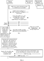
- the antenna port determining method provided in the first embodiment of this application includes the following content:
- a terminal side device receives downlink control information from a network side device, where the downlink control information includes QCL information and indication information that is used to determine an antenna port number of a first antenna port on which downlink data is scheduled, and the QCL information indicates that there is a QCL relationship between a first antenna port and a second antenna port of the network side device.
- the terminal side device determines the first antenna port in the case of transmission with one codeword or transmission with two codewords based on the indication information and the QCL information.
- the network side device may determine the indication information based on the first antenna port on which the downlink data is scheduled.
- the terminal side device may determine that current transmission is NCJT transmission.
- current transmission is not NCJT transmission.
- the indication information is further used to determine at least one (one, two, or more) of a quantity of front-load symbols of the first antenna port and a quantity of code division multiplexing CDM groups corresponding to the first antenna port for rate matching.
- the rate matching means that data bits on a transmission channel between a MAC layer and a PHY layer are repeatedly sent or punctured (that is, repeating and redundant bits are removed), to achieve a required bit rate.
- the first antenna port corresponds to CDM groups during rate matching.
- the scheduled downlink data is not mapped to a resource location corresponding to an antenna port included in the CDM groups.
- the quantity of front-load symbols is a quantity of time domain symbols occupied by one antenna port.
- the first antenna port is a DMRS antenna port on which the downlink data is scheduled is used for description.
- the first antenna port includes at least one DMRS antenna port in a first DMRS group and at least one DMRS antenna port in a second DMRS group.
- FIG. 2 is a schematic diagram of information exchange in a wireless communications system.
- a network side device 1 and the terminal side device may establish a radio bearer (radio bearer, RB) by exchanging an RRC message.
- radio bearer radio bearer, RB
- the network side device 1 may be determined whether the network side device 1 and another network side device can perform the NCJT transmission for the terminal side device.
- the network side device 1 determines a configuration of the NCJT transmission through negotiation with the another network side device, and sends the configuration of the NCJT transmission to the terminal side device by using downlink control information in a specific format.
- the terminal side device detects the downlink control information at regular intervals, the terminal side device learns of a resource location of the scheduled downlink data and other possible configurations.
- the terminal side device detects the configuration of the NCJT transmission in the downlink control information in the specific format (for example, TCI in the downlink control information includes at least two pieces of QCL information, and the downlink control information includes indication information used to determine antenna port numbers of DMRS antenna ports on which the downlink data is scheduled).
- the terminal side device determines, based on the QCL information and the indication information, antenna port numbers of the DMRS antenna ports on which the downlink data is scheduled. Further, the terminal side device receives a DMRS on the DMRS antenna ports corresponding to the DMRS antenna port numbers, performs channel estimation based on the DMRS, and receives the downlink data based on a channel estimation result.
- the terminal side device determines, in the NCJT transmission mode by using table lookup, the DMRS antenna ports on which the downlink data is scheduled.
- the terminal side device further receives a downlink DMRS configuration type parameter and a downlink DMRS maximum length parameter from the network side device.
- the terminal side may obtain the downlink DMRS configuration type parameter and the downlink DMRS maximum length parameter through receiving a higher layer message (such as an RRC message), to determine the required antenna ports.
- the terminal side device establishes a connection to a network side device, and receives a plurality of pieces of QCL information configured by the network side device based on the RRC message.
- the terminal side device learns, based on the detected at least two pieces of QCL information (the at least two pieces of QCL information are included in the plurality of pieces of configured QCL information) indicated by the TCI included in the downlink control information, that current transmission is the NCJT transmission. If the RRC message received by the terminal side device further indicates that the downlink DMRS configuration type parameter is equal to 1, and that the downlink DMRS maximum length parameter is equal to 2, the terminal side device uses Table 2.
- the terminal side device may learn, from Table 2 based on a value 0 of the indication information in the downlink control information, that in the case of transmission with one codeword, DMRS antenna ports on which a DMRS is currently transmitted are the port 0 in the first DMRS group and the port 1002 in the second DMRS group, and in the case of transmission with two codewords, DMRS antenna ports on which a DMRS is currently transmitted are the ports 1000 and 1001 in the first DMRS group and the ports 1002, 1003, and 1006 in the second DMRS group.
- DMRS antenna port 1000+a DMRS port number
- DMRS port number (DMRS ports) 0 2 0; 2 1 2 0; 2, 3 2 2 0, 1; 2 3 2 0; 2, 3, 6 4 2 0, 1; 2, 3 5 2 0, 1, 4; 2 6
- Antenna port 1000+a DMRS port number
- a downlink DMRS maximum length ( DL-DMRS-max-l)
- the terminal side device establishes a connection to a network side device, and receives a plurality of pieces of QCL information configured by the network side device based on the RRC message.
- the terminal side device learns, based on the detected at least two pieces of QCL information (the at least two pieces of QCL information are included in the plurality of pieces of configured QCL information) indicated by the TCI included in the downlink control information, that current transmission is the NCJT transmission. If the RRC message received by the terminal side device further indicates that the downlink DMRS configuration type parameter is equal to 2, and that the downlink DMRS maximum length parameter is equal to 2, the terminal side device uses Table 4.
- the terminal side may learn, from Table 4 based on a value 5 of the indication information in the downlink control information, that in the case of transmission with one codeword, DMRS antenna ports on which a DMRS is currently transmitted are the ports 1000, 1001, and 1006 in the first DMRS group and the port 1002 in the DMRS group, and in the case of transmission with two codewords, DMRS antenna ports on which a DMRS is currently transmitted are the ports 1000, 1001, 1006, and 1007 in the first DMRS group and the ports 1002, 1003, 1008, and 1009 in the second DMRS group.
- a network side device may schedule at least two terminal side devices on a same time-frequency resource.
- DMRSs sent to the at least two terminal sides are orthogonal or quasi-orthogonal.
- a terminal side device 1 establishes a connection to a network side device, and receives a plurality of pieces of QCL information, the downlink DMRS configuration type parameter, and the downlink DMRS maximum length parameter that are configured by the network side device for the terminal side device 1 based on the RRC message.
- the terminal side device 2 establishes a connection with the network side device, and receives a plurality of pieces of QCL information configured by the network side device for the terminal side device 2 based on the RRC message.
- the network side device sends downlink control information 1 to the terminal side device 1.
- the downlink control information 1 indicates at least two pieces of QCL information in the plurality of pieces of QCL information configured for the terminal side device 1, so that the terminal side device 1 learns that current transmission is the NCJT transmission.
- the terminal side device 1 determines a table for usage based on the downlink DMRS configuration type parameter and the downlink DMRS maximum length parameter that are configured for the terminal side device 1, and then determines, based on a specific value of indication information in the downlink control information 1, DMRS antenna ports on which the downlink data is scheduled.
- the network side device further sends downlink control information 2 to the terminal side device 2.
- the downlink control information 2 indicates at least two pieces of QCL information in the plurality of pieces of QCL information configured for the terminal side device 2, so that the terminal side device 2 learns that current transmission is the NCJT transmission.
- the terminal side device 2 determines a table for usage based on the downlink DMRS configuration type parameter and the downlink DMRS maximum length parameter that are configured for the terminal side device 2, and then determines, based on a specific value of indication information in the downlink control information 2, DMRS antenna ports on which the downlink data is scheduled.
- the network side device may enable, based on the downlink DMRS configuration type parameter and the downlink DMRS maximum length parameter, the terminal side device 1 and the terminal side device 2 to search for the required antenna ports by using a same table.
- the specific value of the indication information in the downlink control information 1 is different from the specific value of the indication information in the downlink control information 2, so that the terminal side device 1 and the terminal side device 2 use antenna ports corresponding to different rows in the same table.
- the indication information in the downlink control information 1 is 0, and the DMRS antenna ports on which downlink data of the terminal side device 1 is located are ⁇ 1000, 1002 ⁇ .
- the indication information in the downlink control information 2 is 1, and the DMRS ports on which downlink data of the terminal side device 2 is located are ⁇ 1001, 1003 ⁇ .
- the DMRS antenna ports ⁇ 1000, 1001 ⁇ are from a same CDM group, occupy same time-frequency resources, and are distinguished by using orthogonal codes.
- the DMRS antenna ports ⁇ 1002, 1003 ⁇ are from another same CDM group, occupy same time-frequency resources, and are distinguished by using orthogonal codes.
- the terminal side device learns, based on the at least two pieces of QCL information indicated by the TCI included in the downlink control information, that current transmission is the NCJT transmission.
- a value indicated by the downlink control information received by the terminal side is 5, so that it can be learned from Table 4 that in the case of transmission with one codeword, the DMRS antenna ports on which the DMRS is currently transmitted are the ports 1006 and 1007 in the first DMRS group and the port 1003 in the second DMRS group, and in the case of transmission with two codewords, the DMRS antenna ports on which the DMRS is currently transmitted are the ports 1000, 1001, 1006, and 1007 in the first DMRS group and the ports 1002, 1003, 1008, and 1009 in the second DMRS group.
- the following bit usage analysis table may be obtained. It can be learned from the analysis table that, when the DMRS ports on which the downlink data is scheduled is determined by using different CDM combination manners that is of the two DMRS groups and that corresponds to the indication information in the downlink control information, the antenna ports can be accurately determined, and bit overheads are reduced in general.
- the technical solution provided in the first embodiment may be applied to the MU-MIMO, thereby improving scalability of the entire communications system.
- a second embodiment of this application provides an antenna port determining method.
- Antenna port group information is introduced, so that the terminal side device can determine, based on QCL information in downlink control information, indication information in the downlink control information, and the antenna port group information, the antenna port on which the downlink data is scheduled.
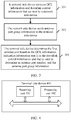
- FIG. 3 is a schematic flowchart of an antenna port determining method, including the following content.
- the terminal side device receives downlink control information sent by a network side device, where the downlink control information includes the QCL information and the indication information that is used to determine an antenna port number of the first antenna port, and the QCL information indicates that there is a quasi-colocation QCL relationship between the first antenna port and a second antenna port.
- the QCL information may specifically indicate that there is the QCL relationship between large-scale properties of the first antenna port and the second antenna port, so that the terminal side device can perform channel estimation based on the large-scale properties of the second antenna port, to further receive data sent by the network side device.
- the QCL relationship includes four types, and may be configured based on a higher layer message (for example, an RRC message): (1) QCL relationship type A: a Doppler frequency shift, a Doppler spread, an average delay, and a delay spread; (2) QCL relationship type B: a Doppler frequency shift and a Doppler spread; (3) QCL relationship type C: an average delay and a Doppler spread; (4) QCL relationship type D: spatial reception.
- a higher layer message for example, an RRC message
- the first antenna port is a DMRS antenna port
- the second antenna port is at least one of a (channel state information reference signal, CSI-RS) antenna port, a synchronization signal block (synchronous signal block, SS block), a phase tracking reference signal (phase tracking reference signal) antenna port, and a tracking reference signal (tracking reference signal, TRS) antenna port.
- CSI-RS channel state information reference signal
- SS block synchronization signal block
- phase tracking reference signal phase tracking reference signal
- TRS tracking reference signal
- a large-scale property of the DMRS antenna port may be inferred based on a large-scale property of at least one of a CSI-RS antenna port, a synchronization signal block, a phase tracking reference signal antenna port, and a tracking reference signal that have the QCL relationship (which may be specifically one of the foregoing four QCL relationship types) with the DMRS antenna port.
- the network side device determines the antenna port group information, and sends the antenna port group information to the terminal side device, where the antenna port group information is used to determine at least one antenna port group.
- the at least two antenna port groups determined based on the antenna port group information include the first antenna port, and optionally, further include the second antenna port.
- the antenna port group information may be carried in a higher layer message (for example, the RRC message) and sent by the network side device to the terminal side device.
- a higher layer message for example, the RRC message
- the at least one antenna port group determined based on the antenna port group information is the at least one DMRS group.
- the terminal side device determines the at least one CDM group based on the identifier of the at least one CDM group, and then determines the at least one DMRS group based on the at least one CDM group.
- the terminal side device determines the at least one DMRS group based on the port number of the at least one DMRS antenna port.
- the terminal side device may pre-store an identifier of each CDM group or a port number of each DMRS antenna port.
- the antenna port group information may alternatively include the at least one CDM group or the at least one DMRS group.
- the terminal side device directly determines the at least one DMRS group directly based on the at least one CDM group. In this case, the terminal side device may not need to store the identifier of each CDM group.
- a quantity of the CDM groups or the at least one DMRS antenna port indicated in the antenna port group information is at least two, and there are also at least two DMRS groups determined based on the antenna port group information.
- the antenna port group information includes identifiers of at least two CDM groups or the two CDM groups and two DMRS groups.
- a first DMRS group in the two DMRS groups includes at least one antenna port in at least one of the at least two CDM groups, and a second DMRS group in the two DMRS groups includes at least one antenna port in another CDM group in the two CDM groups.
- an absolute value of a difference between a quantity of layers of the at least one antenna port included in the first DMRS group and a quantity of layers of the at least one antenna port included in the second DMRS group is greater than 1.
- an absolute value of a difference between a quantity of layers of the at least one antenna port included in the first DMRS group and a quantity of layers of the at least one antenna port included in the second DMRS group is not greater than 1, a first codeword in the two codewords corresponds to the first DMRS group, and a second codeword corresponds to the second DMRS group.
- the terminal side device determines the first antenna port based on the QCL information, the downlink control information, and the antenna port group information.
- the terminal side device may further receive a reference signal on the first antenna port, to perform channel estimation and correctly receive data.
- the terminal side device may further receive a downlink DMRS configuration type parameter and a downlink DMRS maximum length parameter (DL-DMRS-max-len) from the network side device, to determine the DMRS antenna port on which a DMRS is currently transmitted.
- DL-DMRS-max-len downlink DMRS maximum length parameter
- a second embodiment of this application further provides an antenna port determining method.
- the method is based on the first embodiment, and further optimizes the tables in the SU-MIMO and MU-MIMO scenarios in the first embodiment.
- the quantities of bits of the downlink control information in the SU-MIMO scenario are 3 and 6, and the quantities of bits of the downlink control information in the MU-MIMO scenario are 4 and 6.
- the tables in the SU-MIMO and the MU-MIMO scenarios are split into a plurality of sub-tables, and a specific subtable for usage is determined based on the antenna port group information, thereby further reducing signaling overheads of the downlink control information.
- the downlink DMRS configuration type is equal to 2
- Antenna ports included in a first CDM group are ⁇ 1000, 1001, 1006, 1007 ⁇
- antenna ports included in a second CDM group are ⁇ 1002, 1003, 1008, 1009 ⁇
- antenna ports included in a third CDM group are ⁇ 1004, 1005, 1010, 1011 ⁇ .
- the two DMRS groups may have six selection manners:
- the first DMRS group includes at least one antenna port in the first CDM group, and the second DMRS group includes at least one antenna port in the second CDM group;
- the first DMRS group includes at least one antenna port in the first CDM group, and the second DMRS group includes at least one antenna port in the third CDM group;
- the first DMRS group includes at least one antenna port in the second CDM group, and the second DMRS group includes at least one antenna port in the third CDM group;
- the first DMRS group includes at least one antenna port in the first CDM group, and the second DMRS group includes at least one antenna port in the second CDM group and at least one antenna port in the third CDM group;
- the first DMRS group includes at least one antenna port in the first CDM group and at least one antenna port in the second CDM group, and the second DMRS group includes at least one antenna port in the third CDM group;
- the first DMRS group includes at least one
- Table 3 may be split into six subtables, as shown in Table 3-1 to Table 3-6.
- Table 4 may also be split into six subtables, as shown in Table 4-1 to Table 4-6. After the splitting, signaling overheads may be further reduced from six bits used by the indication information in the downlink control information in Table 3 and Table 4 to three bits.
- the terminal side device establishes a connection to a network side device, and receives a plurality of pieces of QCL information configured by the network side device based on the RRC message.
- the terminal side device learns, based on the detected at least two pieces of QCL information (the at least two pieces of QCL information are included in the plurality of pieces of configured QCL information) indicated by TCI included in the downlink control information, that current transmission is NCJT transmission. If the RRC message received by the terminal side device further indicates the downlink DMRS configuration type parameter, the downlink DMRS maximum length parameter, and the antenna port group information, a subtable for usage is specifically determined. Then, the terminal side device determines, based on a specific value of the indication information in the downlink control information, DMRS antenna ports on which the downlink data is scheduled.
- the terminal side device may determine that the current transmission is the NCJT transmission. The terminal side device then determines, based on the antenna port group information, that the first DMRS group includes at least one antenna port in the first CDM group, the second DMRS group includes at least one antenna port in the second CDM group, the downlink DMRS configuration type parameter (DL-DMRS-config-type) received from the higher layer message is equal to 2, and the downlink DMRS maximum length (DL-DMRS-max-len) received from the higher layer message is equal to 1. In this case, Table 3-1 is used.
- DMRS ports corresponding to a row in Table 3-1 are determined based on the specific value of the indication information in the downlink control information. For example, when the specific value is 0, in the case of transmission with one codeword, the DMRS antenna ports on which the downlink data is scheduled are the port 1000 in the first DMRS group and the port 1002 in the second DMRS group.
- a network side device may schedule at least two terminal side devices on a same time-frequency resource.
- DMRSs sent to the at least two terminal sides are orthogonal or quasi-orthogonal.
- the downlink DMRS configuration type is equal to 2
- Antenna ports included in a first CDM group are ⁇ 1000, 1001, 1006, 1007 ⁇
- antenna ports included in a second CDM group are ⁇ 1002, 1003, 1008, 1009 ⁇
- antenna ports included in a third CDM group are ⁇ 1004, 1005, 1010, 1011 ⁇ .
- the two DMRS groups may have six selection manners:
- the first DMRS group includes at least one antenna port in the first CDM group, and the second DMRS group includes at least one antenna port in the second CDM group;
- the first DMRS group includes at least one antenna port in the first CDM group, and the second DMRS group includes at least one antenna port in the third CDM group;
- the first DMRS group includes at least one antenna port in the second CDM group, and the second DMRS group includes at least one antenna port in the third CDM group;
- the first DMRS group includes at least one antenna port in the first CDM group, and the second DMRS group includes at least one antenna port in the second CDM group and at least one antenna port in the third CDM group;
- the first DMRS group includes at least one antenna port in the first CDM group and at least one antenna port in the second CDM group, and the second DMRS group includes at least one antenna port in the third CDM group;
- the first DMRS group includes at least one
- Table 7 may be split into six subtables, as shown in Table 7-1 to Table 7-6.
- Table 8 may also be split into six subtables, as shown in Table 8-1 to Table 8-6.
- signaling overheads may be further reduced from six bits used by the indication information in the downlink control information in Table 7 and Table 8 to four bits.
- a terminal side device 1 establishes a connection to a network side device, and receives a plurality of pieces of QCL information, the downlink DMRS configuration type parameter, the downlink DMRS maximum length parameter, and the antenna port group information that are configured by the network side device for the terminal side device 1 based on the RRC message.
- the terminal side device 2 establishes a connection to the network side device, and receives a plurality of pieces of QCL information configured by the network side device for the terminal side device 2 based on the RRC message.
- the network side device sends downlink control information 1 to the terminal side device 1.
- the downlink control information 1 indicates at least two pieces of QCL information in the plurality of pieces of QCL information configured for the terminal side device 1, so that the terminal side device 1 learns that current transmission is the NCJT transmission.
- the terminal side device 1 determines a subtable for usage based on the downlink DMRS configuration type parameter, the downlink DMRS maximum length parameter, and the antenna port group information that are configured for the terminal side device 1, and then determines, based on a specific value of indication information in the downlink control information 1 in the subtable, DMRS antenna ports on which the downlink data is scheduled.
- the network side device further sends downlink control information 2 to the terminal side device 2.
- the downlink control information 2 indicates at least two pieces of QCL information in the plurality of pieces of QCL information configured for the terminal side device 2, so that the terminal side device 2 learns that current transmission is the NCJT transmission.
- the terminal side device 2 determines a subtable for usage based on the downlink DMRS configuration type parameter, the downlink DMRS maximum length parameter, and the antenna port group information that are configured for the terminal side device 2, and then determines, based on a specific value of indication information in the downlink control information 2 in the subtable, DMRS antenna ports on which the downlink data is scheduled.
- the network side device may enable, based on the downlink DMRS configuration type parameter and the downlink DMRS maximum length parameter, the terminal side device 1 and the terminal side device 2 to search for the required antenna ports by using a same table.
- the specific value of the indication information in the downlink control information 1 is different from the specific value of the indication information in the downlink control information 2, so that the terminal side device 1 and the terminal side device 2 use antenna ports corresponding to different rows in the same table.
- the following bit usage analysis table may be obtained. It can be learned from the analysis table that the terminal side device further determines, based on the received antenna port group information and different antenna port groups, the DMRS ports on which the downlink data is scheduled, to further reduce signaling overheads.
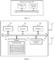
- FIG. 4 is a schematic structural diagram of the terminal side device.
- the terminal side device 400 includes a receiving unit 401 and a processing unit 402.
- the terminal side device 400 provided in the third embodiment of this application may be the terminal side device in the first embodiment or the second embodiment, and performs the method performed by the terminal side device.
- the receiving unit 401 is configured to perform a receiving action of the terminal side device in the first embodiment or the second embodiment
- the processing unit 402 is configured to perform processing actions such as determining of the terminal side device in the first embodiment or the second embodiment.
- FIG. 5 is a schematic structural diagram of the network side device.
- the network side device 500 includes a sending unit 501 and a processing unit 502.
- the network side device 500 may be the network side device in the first embodiment or the second embodiment, and performs the method performed by the network side device.
- the sending unit 501 is configured to perform a sending action of the network side device in the first embodiment or the second embodiment
- the processing unit 502 is configured to perform processing actions such as determining of the network side device in the first embodiment or the second embodiment.
- FIG. 5 is a schematic diagram of a general-purpose hardware structure of a terminal side device and the network side device.
- a function of a receiving unit may be specifically implemented by a receiver 601, a function of a processing unit may be specifically implemented by a processor 602, and a function of a sending unit may be specifically implemented by a transmitter 606.
- the hardware structure may further include various electronic circuits, for example, a bus 603, a memory 604, and a communications interface 605.
- the memory 604 may include instruction code. When the instruction code is invoked by the processor 602, the instruction code is used to implement a function of the terminal side device in the first embodiment or the second embodiment.
- the instruction code may include code used for RRC layer functions, code used for MAC layer functions, and code used for PHY layer functions.
- the memory 604 may be integrated into the processor 602, or may be independent of the processor 602.
- the communications interface 605 may be a wired communications interface, a wireless communications interface, or a combination thereof.
- the wired communications interface may be, for example, an Ethernet interface.
- the Ethernet interface may be an optical interface, an electrical interface, or a combination thereof.
- the wireless communications interface may be a wireless local area network interface.
- the bus may be a peripheral component interconnect (peripheral component interconnect, PCI) standard bus, an extended industry standard architecture (extended industry standard architecture, EISA) bus, or the like.
- PCI peripheral component interconnect
- EISA extended industry standard architecture
- the bus may be classified into an address bus, a data bus, a control bus, and the like.
- this application may be provided as a method, a system, or a computer program product. Therefore, this application may use a form of hardware only embodiments, software only embodiments, or embodiments with a combination of software and hardware. Moreover, this application may use a form of a computer program product that is implemented on one or more computer-usable storage media (including but not limited to a magnetic disk storage, a CD-ROM, an optical memory, and the like) that include computer-usable program code.
- computer-usable storage media including but not limited to a magnetic disk storage, a CD-ROM, an optical memory, and the like
- These computer program instructions may be provided for a processor of a general-purpose computer, a special-purpose computer, an embedded processor, or another programmable data processing device to generate a machine, so that the instructions executed by the processor of the computer or the another programmable data processing device generate an apparatus for implementing a specific function in one or more procedures in the flowcharts and/or in one or more blocks in the block diagrams.
- These computer program instructions may alternatively be stored in a computer-readable memory that can indicate a computer or another programmable data processing device to work in a specific manner, so that the instructions stored in the computer-readable memory generate an artifact that includes an instruction apparatus.
- the instruction apparatus implements a specific function in one or more procedures in the flowcharts and/or in one or more blocks in the block diagrams.
- These computer program instructions may alternatively be loaded onto a computer or another programmable data processing device, so that a series of operations and steps are performed on the computer or the another programmable device, thereby generating computer-implemented processing. Therefore, the instructions executed on the computer or the another programmable device provide steps for implementing a specific function in one or more procedures in the flowcharts and/or in one or more blocks in the block diagrams.
Landscapes
- Engineering & Computer Science (AREA)
- Signal Processing (AREA)
- Computer Networks & Wireless Communication (AREA)
- Physics & Mathematics (AREA)
- Electromagnetism (AREA)
- Mobile Radio Communication Systems (AREA)
Applications Claiming Priority (2)
| Application Number | Priority Date | Filing Date | Title |
|---|---|---|---|
| CN201810130053.3A CN110139366A (zh) | 2018-02-08 | 2018-02-08 | 一种确定天线端口的方法和终端侧设备 |
| PCT/CN2019/074060 WO2019154238A1 (zh) | 2018-02-08 | 2019-01-31 | 一种确定天线端口的方法和终端侧设备 |
Publications (2)
| Publication Number | Publication Date |
|---|---|
| EP3745632A1 true EP3745632A1 (de) | 2020-12-02 |
| EP3745632A4 EP3745632A4 (de) | 2021-03-24 |
Family
ID=67548220
Family Applications (1)
| Application Number | Title | Priority Date | Filing Date |
|---|---|---|---|
| EP19751047.2A Withdrawn EP3745632A4 (de) | 2018-02-08 | 2019-01-31 | Verfahren zur bestimmung eines antennenports und anschlussseitige vorrichtung |
Country Status (4)
| Country | Link |
|---|---|
| US (1) | US11349579B2 (de) |
| EP (1) | EP3745632A4 (de) |
| CN (1) | CN110139366A (de) |
| WO (1) | WO2019154238A1 (de) |
Families Citing this family (11)
| Publication number | Priority date | Publication date | Assignee | Title |
|---|---|---|---|---|
| KR102772305B1 (ko) * | 2018-10-26 | 2025-02-25 | 삼성전자주식회사 | 무선 통신 시스템에서의 논-코히런트 조인트 전송 방법 및 장치 |
| WO2020222605A1 (ko) * | 2019-05-02 | 2020-11-05 | 엘지전자 주식회사 | 무선 통신 시스템에서 데이터 채널의 송수신 방법 및 이에 대한 장치 |
| KR102588873B1 (ko) * | 2019-10-04 | 2023-10-13 | 엘지전자 주식회사 | 무선 통신 시스템에서 신호를 송수신 하는 방법 및 이를 지원하는 장치 |
| WO2021066602A1 (ko) * | 2019-10-04 | 2021-04-08 | 엘지전자 주식회사 | 무선 통신 시스템에서 신호를 송수신 하는 방법 및 이를 지원하는 장치 |
| US12335189B2 (en) * | 2020-02-14 | 2025-06-17 | Nokia Technologies Oy | Multiport phase tracking reference signal in radio communication |
| US12323355B2 (en) * | 2020-04-10 | 2025-06-03 | Qualcomm Incorporated | Demodulation reference signal design for large sub-carrier spacing |
| CN114698104A (zh) * | 2020-12-25 | 2022-07-01 | 华为技术有限公司 | 一种指示天线端口的方法、装置与系统 |
| CN113671270B (zh) * | 2021-07-21 | 2024-06-11 | 西安空间无线电技术研究所 | 一种基于数字开关的天线测试系统及方法 |
| US12596584B2 (en) * | 2022-03-01 | 2026-04-07 | Nvidia Corporation | Application programing interface to indicate concurrent wireless cell capability |
| WO2023173324A1 (en) | 2022-03-16 | 2023-09-21 | Nvidia Corporation | Application programming interface to select storage |
| KR20250101278A (ko) * | 2023-12-27 | 2025-07-04 | 삼성전자주식회사 | 무선 통신 시스템에 있어서 하향링크 참조 신호를 수신하기 위한 방법 및 장치 |
Family Cites Families (10)
| Publication number | Priority date | Publication date | Assignee | Title |
|---|---|---|---|---|
| BR112012016405B1 (pt) * | 2010-01-20 | 2021-06-08 | Telefonaktiebolaget Lm Ericsson (Publ) | método implementado por uma estação base para transmitir sinais de referência de demodulação para um terminal de usuário, método implementado por um terminal de usuário para receber sinais de referência de demodulação transmitidos por uma estação base, estação base, e terminal de usuário |
| AU2013250063B2 (en) * | 2012-04-19 | 2017-11-02 | Samsung Electronics Co., Ltd. | Method and apparatus for quasi co-location identification of reference symbol ports for coordinated multi-point communication systems |
| WO2014046498A1 (ko) * | 2012-09-23 | 2014-03-27 | 엘지전자 주식회사 | 무선 통신 시스템에서 하향링크 제어 신호를 수신 또는 전송하기 위한 방법 및 이를 위한 장치 |
| US9923684B2 (en) * | 2013-01-09 | 2018-03-20 | Samsung Electronics Co., Ltd. | Methods to support inter-eNodeB CoMP |
| EP3050232B1 (de) * | 2013-09-27 | 2020-04-01 | Samsung Electronics Co., Ltd. | Verfahren und vorrichtung zur erkennung von signalen in einer erweiterten lte |
| CN107294574B (zh) * | 2016-04-08 | 2022-04-22 | 华为技术有限公司 | 多传输点数据传输的方法及装置 |
| WO2018021821A1 (ko) * | 2016-07-26 | 2018-02-01 | 엘지전자 주식회사 | 무선 통신 시스템에서 단말의 상향링크 제어 정보 전송 방법 및 이를 지원하는 장치 |
| CN109152054A (zh) * | 2017-06-16 | 2019-01-04 | 华硕电脑股份有限公司 | 无线通信系统中用于非授权频谱的波束管理的方法和设备 |
| CN109391413B (zh) * | 2017-08-10 | 2022-05-10 | 华为技术有限公司 | 信息传输的方法和通信装置 |
| KR102169260B1 (ko) * | 2017-09-08 | 2020-10-26 | 아서스테크 컴퓨터 인코포레이션 | 무선 통신 시스템에서 빔 포밍 전송을 고려한 무허가 스펙트럼에서의 채널 사용 방법 및 장치 |
-
2018
- 2018-02-08 CN CN201810130053.3A patent/CN110139366A/zh active Pending
-
2019
- 2019-01-31 EP EP19751047.2A patent/EP3745632A4/de not_active Withdrawn
- 2019-01-31 WO PCT/CN2019/074060 patent/WO2019154238A1/zh not_active Ceased
-
2020
- 2020-08-07 US US16/988,123 patent/US11349579B2/en active Active
Also Published As
| Publication number | Publication date |
|---|---|
| US20200374017A1 (en) | 2020-11-26 |
| CN110139366A (zh) | 2019-08-16 |
| EP3745632A4 (de) | 2021-03-24 |
| US11349579B2 (en) | 2022-05-31 |
| WO2019154238A1 (zh) | 2019-08-15 |
Similar Documents
| Publication | Publication Date | Title |
|---|---|---|
| US11349579B2 (en) | Antenna port determining method and terminal side device | |
| US10912080B2 (en) | Signal scrambling method and apparatus, and signal descrambling method and apparatus | |
| US11128510B2 (en) | Data transmission method, user equipment, and network side device | |
| US10972171B2 (en) | Data transmission method and apparatus | |
| CN103944665B (zh) | 上行解调参考信号的发送方法、装置和系统 | |
| CN102843209B (zh) | 传输控制信令的方法和装置 | |
| CN102404854B (zh) | 一种上行解调参考信号的资源配置方法及系统 | |
| CN103096493B (zh) | 接收和发送控制信道的方法、用户设备和基站 | |
| EP4007200A1 (de) | Verfahren und vorrichtung zur anzeige eines dmrs-anschlusses | |
| EP3606236B1 (de) | Verfahren und vorrichtung zur bestimmung einer transportblockgrösse | |
| CN103327629B (zh) | 生成dmrs序列、发送dmrs序列初始值的方法和终端、基站 | |
| CN102427396A (zh) | 一种小区间上行解调参考信号的信息交互方法和基站 | |
| CN103326758A (zh) | 下行解调参考信号初始化配置参数通知、接收方法及装置 | |
| US10778287B2 (en) | Multipoint data transmission method and apparatus | |
| CN106559201A (zh) | 传输方式的指示方法及装置 | |
| CN111193581B (zh) | 发送和接收物理下行控制信道的方法以及通信装置 | |
| EP3001743B1 (de) | Verfahren und vorrichtung zur erkennung und sendung von downlink-steuerinformationen | |
| CN106685580A (zh) | 数据处理方法及装置 | |
| CN107294574A (zh) | 多传输点数据传输的方法及装置 | |
| CN108282310B (zh) | 一种数据传输方法、网络侧设备及终端设备 | |
| WO2016169479A1 (zh) | 一种数据传输方法及设备 | |
| CN107925991B (zh) | 一种参考信号配置方法及设备 | |
| CN115037410B (zh) | 通信方法和通信装置 | |
| CN116458104B (zh) | 一种通信方法及装置 |
Legal Events
| Date | Code | Title | Description |
|---|---|---|---|
| STAA | Information on the status of an ep patent application or granted ep patent |
Free format text: STATUS: THE INTERNATIONAL PUBLICATION HAS BEEN MADE |
|
| PUAI | Public reference made under article 153(3) epc to a published international application that has entered the european phase |
Free format text: ORIGINAL CODE: 0009012 |
|
| STAA | Information on the status of an ep patent application or granted ep patent |
Free format text: STATUS: REQUEST FOR EXAMINATION WAS MADE |
|
| 17P | Request for examination filed |
Effective date: 20200824 |
|
| AK | Designated contracting states |
Kind code of ref document: A1 Designated state(s): AL AT BE BG CH CY CZ DE DK EE ES FI FR GB GR HR HU IE IS IT LI LT LU LV MC MK MT NL NO PL PT RO RS SE SI SK SM TR |
|
| AX | Request for extension of the european patent |
Extension state: BA ME |
|
| A4 | Supplementary search report drawn up and despatched |
Effective date: 20210224 |
|
| RIC1 | Information provided on ipc code assigned before grant |
Ipc: H04W 72/04 20090101ALI20210218BHEP Ipc: H04L 25/02 20060101ALI20210218BHEP Ipc: H04L 5/00 20060101AFI20210218BHEP |
|
| DAV | Request for validation of the european patent (deleted) | ||
| DAX | Request for extension of the european patent (deleted) | ||
| STAA | Information on the status of an ep patent application or granted ep patent |
Free format text: STATUS: EXAMINATION IS IN PROGRESS |
|
| 17Q | First examination report despatched |
Effective date: 20230313 |
|
| STAA | Information on the status of an ep patent application or granted ep patent |
Free format text: STATUS: THE APPLICATION IS DEEMED TO BE WITHDRAWN |
|
| 18D | Application deemed to be withdrawn |
Effective date: 20240503 |