EP3745659A1 - Procédé et appareil de routage - Google Patents
Procédé et appareil de routage Download PDFInfo
- Publication number
- EP3745659A1 EP3745659A1 EP18906625.1A EP18906625A EP3745659A1 EP 3745659 A1 EP3745659 A1 EP 3745659A1 EP 18906625 A EP18906625 A EP 18906625A EP 3745659 A1 EP3745659 A1 EP 3745659A1
- Authority
- EP
- European Patent Office
- Prior art keywords
- routing
- path
- node
- routing node
- packet
- Prior art date
- Legal status (The legal status is an assumption and is not a legal conclusion. Google has not performed a legal analysis and makes no representation as to the accuracy of the status listed.)
- Granted
Links
Images






Classifications
-
- H—ELECTRICITY
- H04—ELECTRIC COMMUNICATION TECHNIQUE
- H04L—TRANSMISSION OF DIGITAL INFORMATION, e.g. TELEGRAPHIC COMMUNICATION
- H04L45/00—Routing or path finding of packets in data switching networks
- H04L45/70—Routing based on monitoring results
-
- H—ELECTRICITY
- H04—ELECTRIC COMMUNICATION TECHNIQUE
- H04L—TRANSMISSION OF DIGITAL INFORMATION, e.g. TELEGRAPHIC COMMUNICATION
- H04L45/00—Routing or path finding of packets in data switching networks
- H04L45/12—Shortest path evaluation
- H04L45/124—Shortest path evaluation using a combination of metrics
-
- H—ELECTRICITY
- H04—ELECTRIC COMMUNICATION TECHNIQUE
- H04L—TRANSMISSION OF DIGITAL INFORMATION, e.g. TELEGRAPHIC COMMUNICATION
- H04L45/00—Routing or path finding of packets in data switching networks
- H04L45/12—Shortest path evaluation
- H04L45/123—Evaluation of link metrics
-
- H—ELECTRICITY
- H04—ELECTRIC COMMUNICATION TECHNIQUE
- H04L—TRANSMISSION OF DIGITAL INFORMATION, e.g. TELEGRAPHIC COMMUNICATION
- H04L43/00—Arrangements for monitoring or testing data switching networks
- H04L43/08—Monitoring or testing based on specific metrics, e.g. QoS, energy consumption or environmental parameters
- H04L43/0823—Errors, e.g. transmission errors
- H04L43/0829—Packet loss
-
- H—ELECTRICITY
- H04—ELECTRIC COMMUNICATION TECHNIQUE
- H04L—TRANSMISSION OF DIGITAL INFORMATION, e.g. TELEGRAPHIC COMMUNICATION
- H04L43/00—Arrangements for monitoring or testing data switching networks
- H04L43/08—Monitoring or testing based on specific metrics, e.g. QoS, energy consumption or environmental parameters
- H04L43/0852—Delays
- H04L43/0858—One way delays
-
- H—ELECTRICITY
- H04—ELECTRIC COMMUNICATION TECHNIQUE
- H04L—TRANSMISSION OF DIGITAL INFORMATION, e.g. TELEGRAPHIC COMMUNICATION
- H04L43/00—Arrangements for monitoring or testing data switching networks
- H04L43/08—Monitoring or testing based on specific metrics, e.g. QoS, energy consumption or environmental parameters
- H04L43/0852—Delays
- H04L43/087—Jitter
-
- H—ELECTRICITY
- H04—ELECTRIC COMMUNICATION TECHNIQUE
- H04L—TRANSMISSION OF DIGITAL INFORMATION, e.g. TELEGRAPHIC COMMUNICATION
- H04L45/00—Routing or path finding of packets in data switching networks
- H04L45/64—Routing or path finding of packets in data switching networks using an overlay routing layer
Definitions
- This application relates to the field of network technologies, and in particular, to a routing method and a device.
- a conventional overlay network is a virtualization technology that implements overlaying on a network architecture.
- a general framework of the overlay network is as follows: In the overlay network, a basic network is not greatly modified, and an IP-based basic network technology is mainly used to enable an application to be carried on a network and separated from another network service.
- a common implementation is to encapsulate a data packet into another data packet at a tunnel start point, and decapsulate the encapsulated packet after the encapsulated packet is forwarded to a tunnel end point.
- a physical network is transparent for a terminal system that is different from an overlay edge device and that is connected to the overlay network. In other words, the terminal system does not need to know deployment of the physical network.
- an overlay network is logically divided into two planes: a control plane that is mainly responsible for establishment and maintenance of a virtual tunnel and notification of reachability information of a host, and a forwarding plane that is a physical network carrying an overlay packet.
- the edge device performs tunnel encapsulation on the received packet A based on a tunnel encapsulation protocol and a destination host that needs to be reached by the packet, to obtain a tunnel-encapsulated packet, and then transmits the tunnel-encapsulated packet on the physical network until the tunnel-encapsulated packet reaches a destination edge device of the destination host.
- the destination edge device removes a tunnel header of the received packet to obtain an original packet A, and sends the original packet A to the destination host. That is, the packet A sent by a source host A is transmitted on the physical network and reaches a destination host B.
- QoS Quality of Service
- a routing path is available provided that the routing path is considered by an IP layer to be reachable.
- a routing path considered by the IP layer to be reachable is insufficient to carry transmission of a packet.
- Embodiments of this application provide a routing method and a device, to provide a routing path satisfying a QoS requirement.
- an embodiment of this application provides a routing method.
- the method includes the following steps: A first routing node performs QoS measurement on a path between the first routing node and a reachable adjacent routing node, to obtain a QoS parameter set of the path between every two adjacent routing nodes, where the first routing node is any routing node controlled by a control node; and the first routing node reports the QoS parameter set of the path between every two adjacent routing nodes to the control node.
- the control node calculates a routing path from each routing node to another routing node based on a QoS parameter set that is of a path between every two adjacent routing nodes and that is reported by each routing node, where the another routing node is a routing node that is in routing nodes controlled by the control node and that is different from each routing node.
- the control node sends, to each routing node, one or more routing tables of routing performed from each routing node to the another routing node.
- each routing node After receiving the packet, each routing node determines, from the received one or more routing tables, a routing table corresponding to an identifier of a received packet, and forwards the received packet based on the routing table, where the identifier of the received packet is used to indicate a QoS requirement of the packet.
- the control node calculates a routing path based on a QoS parameter set dynamically measured by each routing node and can obtain routing paths that are of routing performed from each routing node to another routing node and that are based on different QoS parameters. In this way, routing tables of each routing node that are based on the different QoS parameters can be obtained.
- each routing node can determine, based on the routing table corresponding to the identifier of the received packet, a routing path used to forward the packet. To be specific, the determined routing path can satisfy the QoS requirement of the received packet and can carry transmission of the packet.
- each routing node may report a QoS parameter set to the control node in real time, or may periodically report a QoS parameter set to the control node according to an actual requirement. For example, each routing node reports a QoS parameter set once every two seconds (s), every 4s, or every 5s.
- each routing node is a routing node controlled by the control node, and the first routing node is any one of routing nodes controlled by the control node.
- each of the routing tables corresponds to a type of identifier of a packet. Therefore, it is ensured that each routing node can determine, from the routing tables, a routing table corresponding to an identifier of a received packet based on the identifier of the packet.
- the control node when calculating the routing path from each routing node to another routing node based on the QoS parameter set, uses a value of each QoS parameter of the path between every two adjacent routing nodes as a weight value of the path, and substitutes weight values that are in the weight values and that correspond to a same QoS parameter into a Dijkstra's algorithm to obtain routing paths that are of different route types and that are from each routing node to the another routing node.
- a parameter needs to be set for the path between every two adjacent routing nodes during calculation by using the Dijkstra's shortest routing path algorithm.
- a weight value is set for the path between every two adjacent routing nodes.
- the weight value may be a value of a QoS parameter, such as a latency, a packet loss rate, or a jitter, of the path between every two adjacent routing nodes.
- the weight value may be a combination of values of a plurality of QoS parameters, such as fitting of a latency and a packet loss rate, of the path between every two adjacent routing nodes.
- the weight value may be fitting of a value of a QoS parameter and costs of the path between every two adjacent routing nodes.
- the routing path may be a routing path based on a latency, a routing path based on a packet loss rate, a routing path based on a jitter, or a routing path based on a latency and a packet loss rate.
- the control node may calculate the routing path from each routing node to another routing node in real time. Alternatively, the control node may calculate the routing path from each routing node to another routing node according to a specific period. Alternatively, the control node may calculate the routing path from each routing node to another routing node when a difference between a value of at least one QoS parameter in the QoS parameter set and a previously reported value of the QoS parameter is greater than a preset threshold, to avoid route flapping.
- the control node may calculate the routing path from each routing node to another routing node according to a period that is the same as a reporting period of each routing node. Alternatively, the control node may calculate the routing path from each routing node to another routing node according to a period that is different from a reporting period.
- the QoS parameter includes one or more of a latency, a packet loss rate, and a jitter; and when using the value of each QoS parameter of the path between every two adjacent routing nodes as the weight value of the path, the control node may use, as the weight value of the path, an estimated latency obtained by adding a product of a current latency of the path between every two adjacent routing nodes and a first weight to a product of a historical latency and a second weight, where a sum of the first weight and the second weight is 1, and the first weight is a constant or a ratio of a jitter to an average latency of the path between every two adjacent routing nodes; may use, as the weight value of the path, an average packet loss rate of the path between every two adjacent routing nodes, where each item used to calculate the average packet loss rate of the path between every two adjacent routing nodes is a product of a third weight and a packet loss rate that is obtained through each measurement, and the third weight is a sum of 1 and
- a current latency is processed in combination with the current latency, a historical latency, and a jitter of the path between every two adjacent routing nodes.
- a burst increase in a measured latency can also be partially smoothed, and being smoothed herein means reducing impact of a burst latency.
- the average packet loss rate of path between every two adjacent routing nodes is used as the weight value of the path.
- impact of a quantity of continuously lost packets in each period is considered.
- the quantity of continuously lost packets has a relatively large impact on some services such as real-time media services.
- the quantity of continuously lost packets causes frame freezing to the real-time media services.
- the QoS status of the path can be measured more accurately.
- a combination of different QoS parameters is considered.
- transmission efficiency that is calculated based on a latency and a packet loss rate is used as the weight value of the path.
- a value that is obtained by performing weighted averaging on costs and a value of any QoS parameter of the path between every two adjacent routing nodes is used as the weight value of the path.
- the control node when using, as the weight of the path, the average packet loss rate of the path between every two adjacent routing nodes, the control node may use, as the weight value of the path, a difference obtained by subtracting, from 1, a product of the transmission correctness percentage of the path between every two adjacent routing nodes and transmission correctness percentages of all paths passed through by the packet transmitted on the path between every two adjacent routing nodes before the packet reaches the path; and/or when using, as the weight value of the path, the transmission efficiency obtained by multiplying the length of the packet transmitted on the path between every two adjacent routing nodes by the transmission correctness percentage divided by the transmission duration of the packet transmitted on the path between every two adjacent routing nodes, the control node may use a reciprocal of the transmission efficiency as the weight value of the path.
- the difference that is obtained by subtracting, from 1, the product of the transmission correctness percentage of the path between every two adjacent routing nodes and the transmission correctness percentages of all paths passed through by the packet transmitted on the path between every two adjacent routing nodes before the packet reaches the path may be used as the weight value of the path, to more accurately represent a packet loss rate of the path.
- the reciprocal of the transmission efficiency is used as the weight value of the path, to simplify complexity of calculation in which the weight value is substituted into the Dijkstra's algorithm.
- the first routing node when forwarding the received packet based on the routing table, determines a destination routing node corresponding to a destination service point of presence (POP) of the received packet based on a correspondence that is between a service POP and a routing node and that is delivered by the control node; the first routing node determines, from the routing table, a second routing node through which the destination routing node can be reached; and the first routing node forwards the received packet to the second routing node.
- POP destination service point of presence
- the first routing node further receives the correspondence that is between a service POP and a routing node and that is delivered by the control node, to determine the destination routing node corresponding to the destination service POP of the received packet and further to determine the second routing node through which the destination routing node can be reached.
- the first routing node when forwarding the received packet to the second routing node, performs tunnel encapsulation on the received packet based on the second routing node, to obtain a tunnel-encapsulated packet, where the tunnel-encapsulated packet carries a route type, so that the second routing node can determine, based on the route type, a routing table that satisfies the QoS requirement of the packet; and the first routing node forwards the tunnel-encapsulated packet to the second routing node.
- the route type carried in the tunnel-encapsulated packet may be a QoS parameter such as a latency or a packet loss rate, or QoS parameters such as a combination of a latency and a packet loss rate, or may be costs.
- the tunnel-encapsulated packet carries the route type.
- the second routing node may directly determine, based on the route type, a routing table of a routing path used to forward the packet.
- the packet does not need to be further parsed to obtain an identifier of the packet, and a further process of searching for a correspondence between a routing table and an identifier of the packet is not required, either. Therefore, a forwarding latency of the packet is reduced.
- the tunnel-encapsulated packet may further include another field such as Version: a version number, PhLen: a length of a tunnel header, All Ph Len: lengths of all headers, TTL: used to indicate a specific routing node at which a packet is lost, HashKey: a hash value, ToS: used to indicate a feature of a packet, Nheader: a type of an extension header, or Ph CheckSum: a checksum of a header. Reliability of forwarding the packet can be improved by adding these fields.
- HashKey is used to perform a hash on a packet to obtain a hash value. The hash value may be invoked for use during load sharing, and TTL may be used to avoid a packet loop.
- the identifier of the packet is any one of a 5-tuple, a differentiated services code point DSCP, or a type of service ToS.
- the identifier of the packet may have different forms, and the foregoing several forms are merely examples.
- a form of the identifier of the packet is not limited in this embodiment of this application.
- the identifier of the packet is a 5-tuple, it may be required to restrict a port range of an upper-layer user, to improve resource utilization and table lookup performance of each routing node.
- Upper-layer users having a port within a specified range use a same 5-tuple, to reduce information stored in each routing node.
- an embodiment of this application provides a first routing node.
- the first routing node has a function of implementing behavior of the first routing node or one of the routing nodes in the method in the first aspect.
- the function may be implemented by hardware, or may be implemented by hardware executing corresponding software.
- the hardware or the software includes one or more modules corresponding to the foregoing function.
- a specific structure of the first routing node may include a measuring module, a reporting module, a delivering module, and a forwarding module.
- the modules included in the first routing node may perform corresponding functions in the method provided in the first aspect or any possible design of the first aspect.
- an embodiment of this application provides a control node.
- the control node has a function of implementing behavior of the control node in the method in the first aspect.
- the function may be implemented by hardware, or may be implemented by hardware executing corresponding software.
- the hardware or the software includes one or more modules corresponding to the foregoing function.
- a specific structure of the control node may include a receiving module, a calculating module, and a delivering module.
- the modules included in the control node may perform corresponding functions in the method provided in the first aspect or any possible design of the first aspect.
- an embodiment of this application provides a first routing node.
- the first routing node includes a memory configured to store computer executable program code, a communications interface, and a processor, where the processor is coupled to the memory and the communications interface.
- the program code stored in the memory includes an instruction.
- the processor executes the instruction, the instruction enables the first routing node to perform the method performed by the first routing node or by one of the routing nodes in the first aspect or any possible design of the first aspect.
- an embodiment of this application provides a control node.
- the control node includes a memory configured to store computer executable program code, a communications interface, and a processor, where the processor is coupled to the memory and the communications interface.
- the program code stored in the memory includes an instruction. When the processor executes the instruction, the instruction enables the control node to perform the method performed by the control node in the first aspect or any possible design of the first aspect.
- an embodiment of this application provides a computer storage medium that stores an instruction, and when the instruction is run on a computer, the computer is enabled to perform the method in the first aspect or any possible design of the first aspect.
- an embodiment of this application provides a computer program product that includes an instruction, and when the instruction is run on a computer, the computer is enabled to perform the method in the first aspect or any possible design of the first aspect.
- an embodiment of this application provides a chip system.
- the chip system includes a processor, configured to support a first routing node or one of routing nodes, and a control node in implementing the method in the first aspect, for example, generating or processing data and/or information in the method in the first aspect.
- the chip system further includes a memory, where the memory is configured to store a program instruction and data that are necessary for the first routing node or the one of routing nodes, and the control node.
- the processor in the chip system may invoke the program instruction and the data that are stored in the memory in the chip system, so that the chip system can implement functions that can be implemented by the first routing node or the one of routing nodes, and the control node.
- the chip system may include a chip, or may include a chip and another discrete device.
- each routing node performs QoS measurement on a path between each routing node and a reachable adjacent routing node, and reports, to a control node, a QoS parameter set obtained by measuring the path between every two adjacent routing nodes.
- the control node calculates a routing path based on a QoS parameter set dynamically measured by each routing node and can obtain routing paths that are from each routing node to another routing node and that are based on different QoS parameters. In this way, routing tables of each routing node that are based on the different QoS parameters can be obtained.
- each routing node can determine, based on a routing table corresponding to an identifier of the received packet, a routing path used to forward the packet.
- the determined routing path can satisfy a QoS requirement of the received packet and can carry transmission of the packet.
- FIG. 3 is an application scenario according to an embodiment of this application.
- a network architecture includes: an SDN controller, a virtual routing node (or Virtual Router, vRouter), and a physical routing node.
- the vRouter is briefly denoted as vR
- the physical routing node is briefly denoted as R.
- Communication between the SDN controller and each vRouter may be performed by using a transmission control protocol/an internet protocol (Transmission Control Protocol/Internet Protocol, TCP/IP), or an OpenFlow protocol, or another pre-specified communications protocol.
- TCP/IP Transmission Control Protocol/Internet Protocol
- OpenFlow protocol or another pre-specified communications protocol.
- Communication between vRouters and communication between a vRouter and a physical routing node may also be performed by using the TCP/IP protocol.
- the vRouter when a vRouter needs to map a to-be-sent data packet to a physical routing node for transmission, the vRouter sends, by using the TCP/IP protocol, the data packet to the physical routing node to which the data packet is mapped. Communication between physical routing nodes may be performed by using a routing protocol such as open shortest path first (Open Shortest Path First, OSPF), a routing information protocol (Routing Information Protocol, RIP), a border gateway protocol (Border Gateway Protocol, BGP), or another routing protocol.
- the network architecture in FIG. 3 further includes a service POP.
- the service POP may send a packet to a vRouter, or may interact with the SDN controller by using an application server or an application process.
- the network architecture may be logically divided into three layers.
- a first layer is a control layer, including an SDN controller.
- a second layer is an overlay layer, including a plurality of vRouters (vR).
- a third layer is an Internet public network layer, including a plurality of physical routing nodes.
- the first layer is described as the "control layer”
- the second layer is described as the "overlay layer”
- the third layer is described as the "Internet public network layer", which do not constitute a limitation.
- a person of ordinary skill in the art may replace, based on the function implemented by the layer, a name of each layer with another name corresponding to a function of the layer.
- control layer and the overlay layer are not necessarily physically separated.
- control layer and the overlay layer may be disposed on a specific physical routing node at the Internet public network layer, and no dedicated hardware control device is required.
- control layer and the overlay layer may be a server independent of a physical routing node that is on the Internet public network and that is responsible for packet forwarding, or may be installed on a server in a form of software, or even may be installed on a virtual machine of a server in a form of software.
- each vRouter corresponds to at least one physical routing node on an Internet public network.
- one vRouter corresponds to one physical routing node or a plurality of physical routing nodes on the Internet public network.
- “corresponds" means that a vRouter is set according to a physical routing node on the Internet public network, and a routing path between any two vRouters is mapped to a routing path formed by physical routing nodes on the Internet public network.
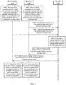
- an embodiment of this application provides a routing method based on quality of service QoS.
- a procedure of the method is described as follows: S401.
- a first routing node performs QoS measurement on a path between the first routing node and a reachable adjacent routing node, to obtain a QoS parameter set of the path between every two adjacent routing nodes, where the first routing node is any routing node controlled by an SDN controller.
- the first routing node is a vR 1 in FIG. 3 is used.
- the first routing node may alternatively be any one of routing nodes vR 1 to vR 7 except the vR 1 in FIG. 3 .
- the reachable adjacent routing node of the first routing node is a routing node that can be reached, through one hop, by a data packet sent by the first routing node.
- the path between every two adjacent routing nodes is a path between the first routing node and an reachable adjacent routing node of the first routing node.
- routing nodes controlled by the SDN controller are the vR 1 to the vR 7.
- reachable adjacent routing nodes of the vR 1 are the vR 2 and the vR 7.
- the first routing node performs QoS measurement on the path between the first routing node and the reachable adjacent routing node, to obtain the QoS parameter set of the path between every two adjacent routing nodes.
- the vR 1 performs QoS measurement on a path from the vR 1 to the vR 2 to obtain a QoS parameter of the path from the vR 1 to the vR 2.
- the vR 1 performs QoS measurement on a path from the vR 1 to the vR 7 to obtain a QoS parameter of the path from the vR 1 to the vR 7.
- the QoS parameter of the path from the vR 1 to the vR 2 and the QoS parameter of the path from the vR 1 to the vR 7 constitute a QoS parameter set.
- the first routing node performs QoS measurement on the path from the first routing node to the reachable adjacent routing node, and another routing node that is controlled by the SDN controller and that is different from the first routing node, for example, another routing node in the vR 1 to the vR 7 except the vR 1, can also perform QoS measurement.
- parameters on which QoS measurement is performed include any one or a combination of a plurality of the following: a latency, a jitter, a packet loss rate, disorder, and the like.
- the vR 1 performs QoS measurement on the path from the vR 1 to the vR 2.
- the latency refers to a period from a time at which the vR 1 sends a data packet to a time at which the vR 2 receives the data packet.
- the jitter refers to an absolute value of a difference between a first latency of receiving one packet by the vR 2 and a second latency of receiving the other packet by the vR 2 when two consecutive packets are sent by the vR 1.
- the packet loss rate refers to a quantity of lost data packets in a transmission process, and may be represented by a packet loss percentage or may be represented by a quantity of lost packets.
- the disorder refers to that a sequence in which the vR 2 receives data packets is different from a sequence in which the vR 1 sends the data packets. Therefore, QoS parameters of the path between every two adjacent routing nodes include any one or a combination of a plurality of the following: a latency, a jitter, a packet loss rate, disorder, and the like.
- the first routing node may use a manner of active measurement, passive measurement, or a combination of passive measurement and active measurement in the prior art.
- the vR 1 is used as an example to describe in detail a process in which the vR 1 performs QoS measurement on the path from the vR 1 to the vR 2 in the manner of active measurement.
- the vR 1 sends a test data packet to the vR 2.
- the vR 1 receives related information fed back by the vR 2, for example, a time at which the vR 2 receives the test data packet sent by the vR 1 and a quantity of test data packets sent by the vR 1.
- the vR 1 may calculate a value of a parameter of the path from the vR 1 to the vR 2, such as a latency, a jitter, a packet loss rate, or disorder, based on related information when the vR 1 sends the test data packet, for example, a time at which the test data packet is sent and a total quantity of sent test data packets.
- test data packet sent by the vR 1 to the vR 2 is actually carried on a physical routing node on the Internet public network for transmission.
- the test data packet sent by the vR 1 are mapped and forwarded from physical routing nodes R 9 to R 1 to R 2 on the Internet public network.
- the vR 1 does not measure a QoS parameter of paths from the R 9 to the R 1 and from the R 1 to the R 2 when the test data packet is transmitted on the paths from the R 9 to the R1 and from the R 1 to the R 2.
- the vR 1 measures a QoS parameter of the path from the vR 1 to the vR 2 when the test data packet is transmitted from the vR 1 to the vR 2.
- the vR 1 performs QoS measurement on the path from the vR 1 to the vR 2
- the vR 2 also performs QoS measurement on a path from the vR 2 to the vR 1.
- the QoS measurement in this embodiment of this application is bidirectional measurement.
- each of results of the bidirectional measurement may be used by the SDN controller. For example, a result obtained by the vR 1 through measurement is used for the path from the vR 1 to the vR 2, and a result obtained by the vR 2 through measurement is used for the path from the vR 2 to the vR 1.
- a unidirectional measurement parameter is obtained through estimation based on results of the bidirectional measurement, and then the parameter of the unidirectional measurement is used for route calculation.
- the unidirectional measurement means that the vR 1 performs QoS measurement on the path from the vR 1 to the vR 2, or the vR 2 performs QoS measurement on the path from the vR 2 to the vR 1.
- a latency and a packet loss rate are measured.
- a unit of the latency is ms (ms), and a unit of the packet loss rate is a percentage.
- ⁇ vR 1, vR 2> ⁇ 1, 0.01 ⁇ . That is, after measuring a latency and a packet loss rate of the path from the vR 1 to the vR 2, the vR 1 obtains QoS parameters ⁇ 1, 0.01 ⁇ .
- QoS parameters may also include a parameter related to a packet loss rate, for example, a maximum quantity of continuously lost packets in each measurement period.
- the first routing node reports the QoS parameter set of the path between every two adjacent routing nodes to the SDN controller, and the SDN controller receives a QoS parameter set reported by each routing node.
- routing nodes may be a plurality of routing nodes that are controlled by the SDN controller and that include the first routing node.
- the routing nodes controlled by the SDN controller in the foregoing example are the vR 1 to the vR 7, and the first routing node may be any routing node in the vR 1 to the vR 7. That is, the SDN controller receives the QoS parameter set that is of the path between every two adjacent routing nodes and that is reported by each routing node in the vR 1 to the vR 7.
- each routing node may report a QoS parameter set to the SDN controller in real time, or may periodically report a QoS parameter set to the SDN controller according to an actual requirement. For example, each routing node reports the QoS parameter set once every two seconds (s), every 4s, or every 5s.
- the SDN controller calculates a routing path from each routing node to another routing node based on the QoS parameter set, where the another routing node is a routing node that is in routing nodes controlled by the SDN controller and that is different from each routing node.
- the routing path from each routing node to another routing node may be a path between the routing node and the adjacent routing node.
- the routing path from each routing node to another routing node may include all paths through which the another routing node is reached after a plurality of hops from each routing node.
- the SDN controller uses a value of each QoS parameter of the path between every two adjacent routing nodes as a weight value of the path.
- a value of one QoS parameter may be used as the weight value of the path.
- a latency, a packet loss rate, or a jitter is used as the weight value of the path.
- a combination of values of a plurality of QoS parameters may be used as the weight value of the path.
- fitting of a latency and a packet loss rate is used as the weight value of the path.
- fitting of costs and a value of one QoS parameter may be used as the weight value of the path.
- a latency is used as a weight value of a path. Specifically, referring to FIG.
- a latency 1 of the path from the vR 1 to the vR 2 is used as a weight value of the path.
- a latency 1 of the path from the vR 2 to the vR 3 is used as a weight value of the path.
- a latency 3 of the path from the vR 2 to the vR 4 is used as a weight value of the path.
- a latency 5 of the path from the vR 3 to the vR 5 is used as a weight value of the path.
- a latency 1 of the path from the vR 4 to the vR 6 is used as a weight value of the path.
- a latency 2 of the path from the vR 5 to the vR 6 is used as a weight value of the path.
- a latency 0 of the path from the vR 6 to the vR 7 is used as a weight value of the path.
- a latency 2 of the path from the vR 1 to the vR 7 is used as a weight value of the
- the SDN controller substitutes weight values that are in the weight values and that correspond to a same QoS parameter into a Dijkstra's algorithm, to obtain, through calculation, routing paths that are of different route types and that are from each routing node to another routing node.
- the different route types may be based on a QoS parameter such as a latency or a packet loss rate, or QoS parameters such as a combination of a latency and a packet loss rate, or may be costs.
- QoS parameter such as a latency or a packet loss rate
- QoS parameters such as a combination of a latency and a packet loss rate
- the SDN controller calculates a latency-based routing path from the first routing node to another routing node.
- the SDN controller calculates a latency-based routing path from the vR 1 to each of the routing nodes ⁇ vR 2, vR 3, vR 4, vR 5, vR 6, vR 7 ⁇ .
- the vR 1 is centered, and reachable adjacent routing nodes of the vR 1 are the vR 2 and the vR 7.
- a latency of the path from the vR 1 to the vR 2 is 1, and a latency of the path from the vR 1 to the vR 7 is 2.
- the vR 2 is used as a next-hop routing node of routing performed from the vR 1 to the vR 5. Then, the vR 2 is centered, and reachable adjacent routing nodes of the vR 2 are the vR 3 and the vR 4. A latency of the path from the vR 2 to the vR 3 is 1, and a latency of the path from the vR 2 to the vR 4 is 3.
- the vR 3 is used as a next-hop routing node of routing performed from the vR 2 to the vR 5.
- the vR 3 is centered, and a reachable adjacent routing node of the vR 3 is the vR 5.
- a latency of the path from the vR 3 to the vR 5 is 5, less than a latency that is of a path from the vR 2 to the vR 4 to the vR 6 to the vR 5 and that is 6. Therefore, it is determined that a routing path from the vR 1 to the vR 5 is a path from the vR 1 to the vR 2 to the vR 3 to the vR 5 and a latency of the routing path is 7.
- the SDN controller may calculate a routing path from the vR 1 to each of the vR 2, the vR 3, the vR 4, the vR 6, and the vR 7, and a latency-based routing path of another routing node that is in the routing nodes and that is different from the first routing node, for example, a routing path from the vR 2 to each of the vR 1, the vR 3, the vR 4, the vR 5, the vR 6, and the vR 7, a routing path from the vR 3 to each of the vR 1, the vR 2, the vR 4, the vR 5, the vR 6, and the vR 7, ..., and a routing path from the vR 7 to each of the vR 1, the vR 2, the vR 3, the vR 4, the vR 5, and the vR 6.
- a next-hop routing node of routing performed from the first routing node to another routing node can be obtained based on the calculated routing path from the first routing node to another routing node. Then, a routing table of the first routing node is further obtained.
- an obtained routing table of each routing node is based on a latency. Specifically, FIG.
- each routing table includes three items.
- a first item is an IP address and a port number of a destination routing node, namely, another routing node of routing performed from each routing node.
- a second item is an IP address and a port number of a next-hop routing node of routing performed from each routing node to another routing node.
- a third item is a route type, such as a latency that is used as an example in FIG. 6 .
- a packet loss rate of the path between every two adjacent routing nodes may also be used as the weight value of the path, to calculate a routing path that is from each routing node to another routing node and that is based on a packet loss rate.
- fitting of a latency and a packet loss rate of the path between every two adjacent routing nodes is used as the weight value of the path, to calculate a routing path that is from each routing node to another routing node and that is based on a latency and a packet loss rate.
- costs of the path between every two adjacent routing nodes are used as the weight value of the path, to calculate a routing path that is from each routing node to another routing node and that is based on costs.
- routing tables that are based on a packet loss rate, based on a latency and a packet loss rate, and based on costs are obtained.
- a specific implementation process of calculating the routing path is the same as that of calculating a latency-based routing table of each routing node. Details are not described herein again.
- the SDN controller smooths each QoS parameter before using the value of each QoS parameter of the path between every two adjacent routing nodes as the weight value of the path, to more accurately represent a QoS status of the path between every two adjacent routing nodes. Descriptions are separately provided in the following parts.
- the SDN controller uses, as the weight value of the path, an estimated latency obtained by adding a product of a current latency of the path between every two adjacent routing nodes and a first weight to a product of a historical latency and a second weight.
- an example in which a latency that is of a path between the first routing node and a reachable adjacent routing node and that is reported by the first routing node is used. It is assumed that the first routing node reports a latency of the path to the SDN controller according to a specific period.
- a current latency of the path is denoted as RTT i , indicating a latency reported by the first routing node in the i th period.
- a historical latency of the path is denoted as RTT i , indicating a latency reported by the first routing node in the (i-1) th period.
- a first weight of the current latency is denoted as ⁇
- a second weight of the historical latency may be denoted as 1 - ⁇ .
- ⁇ may be a constant value, or may be a ratio of a jitter of the path to an average latency.
- ⁇ is a constant value, ⁇ is greater than 0 and less than 1.
- a process in which the SDN controller processes a latency of another path between every two adjacent routing nodes is the same as a process in which the SDN controller processes a latency of the path between the first routing node and the reachable adjacent routing node. Details are not described herein again.
- a current latency is processed in combination with the current latency, a historical latency, and a jitter of the path between every two adjacent routing nodes.
- rapid convergence can be implemented.
- a burst increase in a current latency can also be partially smoothed, and being smoothed herein means reducing impact of a burst latency.
- an example in which the path from the vR 1 to the vR 2 in FIG. 5 is used.
- a current latency of 1 ms, a historical latency of 0.5 ms, a jitter of 0.5 ms, and an average latency of 0.75 ms of the path from the vR 1 to the vR 2 are substituted into the formula (2), and then an estimated latency of the path can be calculated as 5/6 ms.
- the estimated latency of 5/6 ms is used as a weight value of the path.
- a routing path from the first routing node to another routing node is calculated based on an estimated latency of the path between every two adjacent routing nodes.
- the SDN controller uses, as the weight value of the path, an average packet loss rate of the path between every two adjacent routing nodes.
- an average packet loss rate of the path between every two adjacent routing nodes.
- a packet loss rate and a maximum quantity of continuously lost packets of a path that is between the first routing node and a reachable adjacent routing node and that is reported by the first routing node is used. It is assumed that the first routing node reports a packet loss rate and a maximum quantity of continuously lost packets to the SDN controller according to a specific period, and there is a total of N periods for reporting.
- a packet loss rate measured in the n th period is denoted as LostRate n .
- LostRate 1 N L N + L N ⁇ 1 + ⁇ + L 1
- LostRate 1 2 ⁇ L N + 1 4 ⁇ L N ⁇ 1 + ⁇ + 1 2 N ⁇ L 1 + 1 2 N ⁇ L 1
- a process in which the SDN controller processes a packet loss rate of another path between every two adjacent routing nodes is the same as a process in which the SDN controller processes a packet loss rate of the path between the first routing node and the reachable adjacent routing node. Details are not described herein again.
- the maximum quantity of continuously lost packets has a relatively large impact on some services (such as real-time media services). For example, the maximum quantity of continuously lost packets causes frame freezing to the real-time media services.
- a packet loss rate status of the path can be measured more accurately, ensuring that a calculated routing path based on a packet loss rate can carry transmission of the packet.
- path indicates paths passed through by a packet in a forwarding process, and i indicates one of the paths.
- the first routing node vR 1 receives a packet sent by a source POP, and then needs to forward the packet to a destination routing node vR 3.
- the packet passes through the path from the vR 1 to the vR 2
- a calculated average packet loss rate of the path from the vR 1 to the vR 2 is 0.01, 0.01 is used as a weight value of the path from the vR 1 to the vR 2.
- the packet passes through the path from the vR 2 to the vR 3.
- the SDN controller uses, as the weight value of the path, transmission efficiency obtained by multiplying a length of the packet transmitted on the path between every two adjacent routing nodes by a transmission correctness percentage divided by transmission duration of the packet transmitted on the path between every two adjacent routing nodes.
- a path between the first routing node and a reachable adjacent routing node is used as an example.
- a length of a packet transmitted on the path is denoted as L
- transmission duration of the packet transmitted on the path is denoted as T
- an average packet loss rate of the path is denoted as LostRate path
- Q transmission efficiency of transmitting the packet on the path
- Q may be represented by a formula (7):
- Q L ⁇ 1 ⁇ LostRate path T
- the transmission duration T of the packet transmitted on the path is a sum of a half of an estimated latency and a value obtained by dividing the length of the packet by a bandwidth B of the path.
- RTT the estimated latency of the path
- LostRate path in the formula (7) may be calculated according to the formula (6)
- RTT in the formula (8) may be calculated according to the formula (2). Details are not described herein again.
- a process in which the SDN controller processes fitting of a latency and a packet loss rate of another path between every two adjacent routing nodes is the same as a process in which the SDN controller processes fitting of the latency and the packet loss rate of the path between the first routing node and the reachable adjacent routing node. Details are not described herein again.
- a reciprocal of the transmission efficiency may be used as the weight value of the path in a specific implementation process. That is, 1 / Q is used as the weight value of the path.
- the path from the vR 1 to the vR 2 in FIG. 5 is still used as an example.
- the estimated latency of the path from the vR 1 to the vR 2 is 5/6 (ms) according to a calculated result in Part 1.
- the average packet loss rate of the path from the vR 1 to the vR 2 is 0.01 according to a calculated result in Part 2.
- transmission efficiency Q of the path may be calculated as (1 - 0.01)/(1/(256 x 1000) + 5/(2 x 12 x 8 x 6)) according to the formula (7) and the formula (8), where a unit of Q is bit/ms. Then, 1 / Q , to be specific, (1/(256 x 1000) + 5/(2 x 12 x 8 x 6))/(1 - 0.01) is used as a weight value of the path.
- the SDN controller uses, as the weight value of the path, a value obtained by adding a product of costs of the path between every two adjacent routing nodes and a fourth weight to a product of a value of any QoS parameter and a fifth weight.
- a sum of the fourth weight and the fifth weight is 1, and the fourth weight is greater than or equal to 0 and less than or equal to 1.
- a path between the first routing node and a reachable adjacent routing node is used as an example. If a fourth weight of the path is denoted as ⁇ , then a fifth weight may be represented as 1 - ⁇ .
- Costs C of the path from the vR 1 to the vR 2 are a sum of outflow costs generated when a packet is sent by the vR 1 and inflow costs generated when the packet is received by the vR 2. For details, refer to FIG. 7 .
- a process in which the SDN controller processes costs of another path between every two adjacent routing nodes is the same as a process in which the SDN controller processes costs of the path between the first routing node and the reachable adjacent routing node. Details are not described herein again.
- the SDN controller may calculate the routing path from each routing node to another routing node in real time. Alternatively, the SDN controller may calculate the routing path from each routing node to another routing node according to a specific period. Alternatively, the SDN controller may calculate the routing path from each routing node to another routing node when a difference between a value of at least one QoS parameter in the QoS parameter set and a previously reported value of the QoS parameter is greater than a preset threshold, to avoid route flapping.
- the SDN controller may calculate the routing path from each routing node to another routing node according to a period that is the same as a reporting period of each routing node. Alternatively, the SDN controller may calculate the routing path from each routing node to another routing node according to a period that is different from a reporting period. Alternatively, the SDN controller may calculate the routing path from each routing node to another routing node when a difference between a value of at least one QoS parameter in the QoS parameter set and a previously reported value of the QoS parameter is greater than a preset threshold, to avoid route flapping.
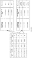
- an objective of calculating routing tables of each routing node that are based on different QoS parameters is to satisfy QoS requirements of different packets. Therefore, after routing tables that are of routing performed from each routing node to another routing node and that are based on different QoS parameters are determined, a correspondence between a routing table and an identifier of a packet further needs to be established.
- Each routing table corresponds to a type of identifier of a packet. For details, refer to FIG. 8A .
- each routing node after receiving a packet, each routing node can determine a routing path of the packet based on a routing table that satisfies a QoS requirement of the packet, thereby ensuring that the determined routing path can carry transmission of the packet.
- an identifier of a packet may be represented by using a 5-tuple, or may be represented by using a differentiated services code point (Differentiated Services Code Point, DSCP). Descriptions are separately provided below.
- DSCP differentiated Services Code Point
- An identifier of a packet is represented by using a 5-tuple.
- the 5-tuple includes a source IP, a destination IP, a source port, a destination port, and a protocol type of a packet.
- an identifier, corresponding to a latency-based routing table, of a packet is a 5-tuple that includes a source IP: 11.1.1.1, a source port: 60001, a destination IP: 66.1.1.1, a destination port: 60001, and a protocol type: 17.
- An identifier, corresponding to a routing table that is based on a packet loss rate, of a packet is a 5-tuple that includes a source IP: 11.1.1.2, a source port: 50001, a destination IP: 66.1.1.2, a destination port: 50001, and a protocol type: 6.
- An identifier of a packet is represented by using a DSCP.
- the SDN controller maps the routing table to a DSCP with a fixed value.
- a routing table that is based on a packet loss rate corresponds to an identifier that is of a packet and that is a DSCP with a value of AF4
- a latency-based routing table corresponds to an identifier that is of a packet and that is a DSCP with a value of EF
- a routing table that is based on costs corresponds to an identifier that is of a packet and that is a DSCP with a value of BE.
- a value of a DSCP is represented in two manners: a keyword form and a digital form, where AF4, EF, and BE are keyword forms.
- AF4 a digital form of AF4
- EF a digital form of EF
- BE a digital form of BE
- an identifier of a packet may be further represented by using a type of service ToS in addition to a 5-tuple or a DSCP. Regardless of whether an identifier of a packet is represented by a 5-tuple, a DSCP, or a ToS, these fields are carried in a packet header of a packet.
- the SDN controller delivers, to each routing node, one or more routing tables of routing performed from each routing node to another routing node, and each routing node receives the one or more routing tables delivered by the SDN controller.
- the SDN controller delivers, to each routing node, one or more routing tables of routing performed from each routing node to another routing node instead of to another routing node, to improve resource utilization of each routing node.
- the SDN controller delivers, to the vR 1 instead of to another routing node different from the vR 1, a routing table of routing performed from the vR 1 to another routing node.
- the SDN controller delivers, to each routing node, a mapping table or a correspondence between an identifier of a packet and a routing table of routing performed from each routing node to another routing node.
- the SDN controller may deliver, to each routing node by using the TCP/IP protocol or the OpenFlow protocol, the one or more routing tables of routing performed from each routing node to another routing node.
- the SDN controller sends, to each routing node, the one or more routing tables of routing performed from each routing node to another routing node, so that after receiving a packet, each routing node determines, from the received one or more routing tables, a routing table corresponding to an identifier of the received packet, and then forwards the received packet based on the routing table.
- the following uses an example in which the first routing node receives one or more routing tables delivered by the SDN controller, to describe a process in which the first routing node forwards a received packet based on the received one or more routing tables.
- a process in which another routing node that is in the routing nodes and that is different from the first routing node forwards a received packet sent by a source service POP is the same as that of the first routing node. Details are not described herein again.
- the first routing node receives a packet, determines, from the one or more routing tables, a routing table corresponding to an identifier of the packet, and forwards the received packet based on the routing table.
- each routing node can determine, based on the routing table corresponding to the identifier of the packet, a routing path used to forward the packet.
- the determined routing path can satisfy the QoS requirement of the received packet and can carry transmission of the packet.
- the first routing node in addition to receiving the one or more routing tables delivered by the SDN controller, the first routing node further receives a correspondence that is between a service POP and a routing node and that is delivered by the SDN controller.
- the first routing node also needs to report, to the SDN controller, a service POP corresponding to the first routing node.
- the vR 1 reports, to the SDN controller, a service POP 11, a service POP 12, and a service POP 13 that belong to the vR 1.
- another routing node that is in the routing nodes controlled by the SDN controller and that is different from the first routing node may also report, to the SDN controller, a service POP that belongs to the another routing node.
- the vR 2 reports a service POP 21, a service POP 22, and a service POP 23 that belong to the vR 2 to the SDN controller
- the vR 7 reports a service POP 71, a service POP 72, and a service POP 73 that belong to the vR 7 to the SDN controller.
- the first routing node may alternatively report, to the SDN controller, an identifier that is used to represent a service POP.
- the identifier may be an IP address of the service POP.
- the SDN controller After receiving the service POP reported by each routing node, the SDN controller establishes a correspondence between a routing node and a service POP. For details, refer to FIG. 9 .
- the first routing node determines, based on the correspondence between a service POP and a routing node, a destination routing node corresponding to a destination service POP of the packet, and determines, from the one or more routing tables, a routing table corresponding to an identifier of the packet. In other words, the first routing node determines a routing table corresponding to an identifier of the packet based on the correspondence in FIG. 8A .
- the destination routing node may be first determined, and then the routing table corresponding to the identifier of the packet is determined.
- the routing table corresponding to the identifier of the packet may be first determined, and then the destination routing node is determined.
- the two steps may be performed simultaneously. This is not limited herein.
- a second routing node through which the received packet can reach the destination routing node is determined from the routing table corresponding to the identifier of the packet, and then the first routing node forwards the received packet to the second routing node.
- the first routing node determines, from the routing table corresponding to the identifier of the packet, a next-hop routing node through which the received packet can reach the destination routing node, and then forwards the received packet to the next-hop routing node.
- the determined routing table corresponds to the identifier of the received packet
- the determined routing table correspond to the QoS requirement of the received packet.
- the routing path determined based on the routing table can satisfy the QoS requirement of the received packet. In other words, the routing path determined based on the routing table can carry transmission of the received packet.
- the first routing node may perform tunnel encapsulation on the received packet based on the second routing node.
- the first routing node may perform encapsulation by using a tunnel encapsulation protocol in the prior art, for example, a virtual extensible local area network (Virtual Extensible LAN, VXLAN) or generic routing encapsulation (Generic Routing Encapsulation, GRE), or may perform encapsulation by using another tunnel encapsulation protocol.
- a tunnel encapsulation protocol in the prior art, for example, a virtual extensible local area network (Virtual Extensible LAN, VXLAN) or generic routing encapsulation (Generic Routing Encapsulation, GRE), or may perform encapsulation by using another tunnel encapsulation protocol.
- VXLAN Virtual Extensible LAN
- GRE Generic Routing Encapsulation
- This embodiment of this application provides another tunnel encapsulation protocol.
- a tunnel-encapsulated packet carries a route type.
- the second routing node may determine a routing table corresponding to the packet based on the route type carried in a tunnel header. The correspondence in FIG. 8A is not needed to determine the routing table corresponding to the identifier of the packet, thereby reducing a forwarding latency of the packet.
- the route type carried in the tunnel-encapsulated packet may be a QoS parameter such as a latency or a packet loss rate, or QoS parameters such as a combination of a latency and a packet loss rate, or may be costs.
- the tunnel-encapsulated packet may further include another field such as Version: a version number, PhLen: a length of a tunnel header, All Ph Len: lengths of all headers, TTL: used to indicate a specific routing node at which a packet is lost, HashKey: a hash value, ToS: used to indicate a feature of a packet, Nheader: a type of an extension header, or Ph CheckSum: a checksum of a header.
- HashKey is used to perform a hash operation on a packet to obtain a hash value. The hash value may be invoked for use during load sharing, and TTL may be used to avoid a packet loop.
- FIG. 10 shows a format of a tunnel encapsulation according to an embodiment of this application.
- a tunnel encapsulation format further includes a conventional field, an internet protocol (Internet Protocol, IP) packet header and a user datagram protocol (User Datagram Protocol, UDP) packet header.
- IP Internet Protocol
- UDP User Datagram Protocol
- the IP packet header and the UDP packet header have a total length of 28 bytes.
- the IP header includes a source IP address, to be specific, an IP address of the first routing node that receives a packet sent by a service POP, and a destination IP address, to be specific, an IP address of a next-hop routing node through which a destination routing node corresponding to a destination service POP of the packet is reached, which is also referred to as an IP address of the second routing node.
- the UDP packet header carries a source port number, to be specific, a port number of the first routing node that receives a packet sent by a service POP, and a destination port number, to be specific, a port number of a next-hop routing node through which a destination routing node corresponding to a destination service POP of the packet is reached, which is also referred to as a port number of the second routing node.
- the following describes, with reference to a specific example, the process in which the first routing node forwards the received packet.
- the first routing node is the vR 1
- the vR 1 receives a packet sent by the service POP 11
- a destination service POP of the packet is the service POP 31 is used.
- a packet sent by the service POP 11 carries an IP address of the service POP 11 and an IP address of the service POP 31.
- the IP address of the service POP 11 is 66.66.66.66
- the IP address of the service POP 31 is 88.88.88.88
- an IP address of the routing node vR 1 that corresponds to the service POP 11 is 1.1.1.1.
- the vR 1 determines, based on the correspondence between a service POP and a routing node, a destination routing node corresponding to the service POP 31, that is, the vR 3 in FIG. 11 .
- An IP address of the vR 3 is 3.3.3.3.
- the vR 1 further needs to parse the received packet to obtain an identifier of the packet. For example, a DSCP field in a packet header is checked, a ToS field in a packet header is checked, or 5-tuple information carried in a packet header is checked. In this case, an example in which the DSCP field in the packet header is checked, and a determined value of the DSCP is EF is used. It should be noted herein that before the service POP 11 sends a packet to the vR 1, the service POP 11 reports, by using an application server or an application process, a QoS requirement of the packet that is to be sent to the SDN controller.
- the reported QoS requirement indicates a higher priority of a latency requirement, or a higher requirement of a packet loss rate, or a higher priority of cost requirement.
- a priority of a latency requirement is higher is used.
- the SDN controller After receiving the QoS requirement, the SDN controller returns a value, such as EF, that is of the DSCP and that corresponds to the QoS requirement to the service POP 11.
- the service POP 11 adds the value of the DSCP to the packet header based on the value of the DSCP, and then sends the packet to the vR 1.
- the vR 1 After determining the value of the DSCP, the vR 1 determines, from the one or more routing tables, a routing table corresponding to the identifier of the packet based on the correspondence in FIG. 8B . In other words, the vR 1 determines a routing table corresponding to EF. Then, the vR 1 determines a second routing node, that is, a routing node whose IP address is 2.2.2.2 and port number is 8000 in FIG. 11 and through which the received packet can reach the destination routing node. After determining the second routing node, the vR 1 performs encapsulation on the packet by using the tunnel encapsulation format described in FIG. 10 .
- An IP packet header includes a source IP address: 1.1.1.1 and a destination IP address: 2.2.2.2.
- a UDP packet header includes a source port number: 8000 and a destination port number: 8000. Corresponding content is added to another field. Details are not described herein again.
- the vR 1 forwards a tunnel-encapsulated packet to the second routing node.
- the second routing node removes a tunnel header of the received tunnel-encapsulated packet, and determines whether the destination routing node is the second routing node based on the destination routing node that corresponds to the destination service POP and that is carried in the packet header of the packet. If the destination routing node is not the second routing node, the second routing node directly determines a routing table corresponding to a route type based on the route type carried in a tunnel header, to determine, from the routing table of the route type, a next-hop routing node through which the received packet can reach the destination routing node.
- the next-hop routing node herein is a next-hop routing node, namely, the vR 3 in FIG. 11 , of the second routing node.
- An IP address of the vR 3 is 3.3.3.3.
- the second routing node performs, based on the next-hop routing node, encapsulation on the packet by using the tunnel encapsulation format described in FIG. 10 .
- An IP packet header includes a source IP address: 2.2.2.2 and a destination IP address: 3.3.3.3.
- a UDP packet header includes a source port number: 8000 and a destination port number: 8000.
- the second routing node may further modify another field in the tunnel header according to an actual requirement.
- a value of TTL decreases by 1 each time the packet is forwarded.
- the second routing node vR 2 forwards the tunnel-encapsulated packet to the vR 3.
- the vR 3 removes a tunnel header of the tunnel-encapsulated packet and determines whether the destination routing node is the vR 3 based on the destination routing node that corresponds to the destination service POP and that is carried in the packet header of the packet. If the destination routing node is the vR 3, the vR 3 forwards the packet to the destination service POP, that is, the service POP 31 that corresponds to an IP address: 88.88.88.88 in FIG. 11 .
- FIG. 12 is a schematic structural diagram of a first routing node 1200.
- the first routing node 1200 may include a measuring module 1201, a reporting module 1202, a receiving module 1203, and a forwarding module 1204.
- the measuring module 1201 may be configured to perform S401 in the embodiment in FIG. 4 , and/or support another process of the technology described in this specification.
- the reporting module 1202 may be configured to perform S402 in the embodiment in FIG. 4 , and/or support another process of the technology described in this specification.
- the receiving module 1203 may be configured to perform S404 in the embodiment in FIG. 4 , and/or support another process of the technology described in this specification.
- the forwarding module 1204 may be configured to perform S405 in the embodiment in FIG. 4 , and/or support another process of the technology described in this specification. All related content of the steps in the foregoing method embodiment may be cited in function descriptions of corresponding function modules. Details are not described herein again.
- FIG. 13 is a schematic structural diagram of a control node 1300.
- the control node 1300 may include a receiving module 1301, a calculating module 1302, and a delivering module 1303.
- the receiving module 1301 may be configured to perform S402 in the embodiment in FIG. 4 , and/or support another process of the technology described in this specification.
- the calculating module 1302 may be configured to perform S403 in the embodiment in FIG. 4 , and/or support another process of the technology described in this specification.
- the delivering module 1303 may be configured to perform S404 in the embodiment in FIG. 4 , and/or support another process of the technology described in this specification. All related content of the steps in the foregoing method embodiment may be cited in function descriptions of corresponding function modules. Details are not described herein again.
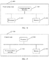
- FIG. 14 is a schematic structural diagram of a first routing node 1400.
- the first routing node 1400 may include a communications interface 1401, a processor 1402, and a memory 1403.
- the processor 1402 is coupled to the memory 1403 and the communications interface 1401.
- the processor 1402 may be a central processing unit (CPU) or an application-specific integrated circuit (Application Specific Integrated Circuit, ASIC), may be one or more integrated circuits configured to control execution of a program, may be a baseband chip, or the like.
- the memory may be a read-only memory (Read-only Memory, ROM), a random access memory (Random Access Memory, RAM), a magnetic disk memory, or the like.
- the memory 1403 is configured to store a computer executable instruction.
- the processor 1402 executes the computer executable instruction stored in the memory 1403, so that the first routing node 1400 implements the routing method that is based on quality of service QoS and that is provided in the embodiment in FIG. 4 .
- the processor 1402 executes the computer executable instruction stored in the memory 1403, so that the first routing node 1400 implements the routing method that is based on quality of service QoS and that is provided in the embodiment in FIG. 4 .
- FIG. 15 is a schematic structural diagram of a control node 1500.
- the control node 1500 may include a processor 1501, a communications interface 1502, and a memory 1503.
- the processor 1501 is coupled to the communications interface 1502 and the memory 1503.
- the processor 1501 may be a central processing unit (CPU) or an application-specific integrated circuit (Application Specific Integrated Circuit, ASIC), may be one or more integrated circuits configured to control execution of a program, may be a baseband chip, or the like.
- the memory may be a read-only memory (Read-only Memory, ROM), a random access memory (Random Access Memory, RAM), a magnetic disk memory, or the like.
- the memory 1503 is configured to store a computer executable instruction.
- the processor 1501 executes the computer executable instruction stored in the memory 1503, so that the first routing node 1500 implements the routing method that is based on quality of service QoS and that is provided in the embodiment in FIG. 4 .
- the routing method based on quality of service QoS
- An embodiment of this application further provides a computer storage medium.
- the storage medium may include a memory, and the memory may store a program. When the program is executed, all steps performed by the first routing node and the SDN controller described in the method embodiment in FIG. 4 are performed.
- An embodiment of this application further provides a computer program product.
- the program product is invoked and executed by a computer, the computer is enabled to execute the method provided in the method embodiment in FIG. 4 .
- An embodiment of this application further provides a chip system.
- the chip system includes a processor, configured to support a first routing node or one of routing nodes, and an SDN controller in implementing the method provided in the embodiment in FIG. 4 , for example, generating or processing data and/or information in the method provided in the embodiment in FIG. 4 .
- the chip system further includes a memory, where the memory is configured to store a program instruction and data that are necessary for the first routing node or the one of routing nodes, and the SDN controller.
- the processor in the chip system may invoke the program instruction and the data that are stored in the memory in the chip system, so that the chip system can implement functions that can be implemented by the first routing node or the one of routing nodes, and the SDN controller.
- the chip system may include a chip, or may include a chip and another discrete device.
- this application may be provided as a method, a system, or a computer program product. Therefore, this application may use a form of hardware only embodiments, software only embodiments, or embodiments with a combination of software and hardware. Moreover, this application may use a form of a computer program product that is implemented on one or more computer-usable storage media (including but not limited to a disk memory, a CD-ROM, an optical memory, and the like) that include computer usable program code.
- a computer-usable storage media including but not limited to a disk memory, a CD-ROM, an optical memory, and the like
- These computer program instructions may be provided for a general-purpose computer, a dedicated computer, an embedded processor, or a processor of another programmable data processing device to generate a machine, so that the instructions executed by the computer or the processor of the another programmable data processing device generate an apparatus for implementing a specific function in one or more processes in the flowcharts and/or in one or more blocks in the block diagrams.
- these computer program instructions may be stored in a computer readable memory that can instruct a computer or another programmable data processing device to work in a specific manner, so that the instructions stored in the computer readable memory generate an artifact that includes an instruction apparatus.
- the instruction apparatus implements a specific function in one or more processes in the flowcharts and/or in one or more blocks in the block diagrams.
- these computer program instructions may also be loaded onto a computer or another programmable data processing device, so that a series of operations and steps are performed on the computer or the another programmable device, thereby generating computer-implemented processing. Therefore, the instructions executed on the computer or the another programmable device provide steps for implementing a specific function in one or more processes in the flowcharts and/or in one or more blocks in the block diagrams.
Landscapes
- Engineering & Computer Science (AREA)
- Computer Networks & Wireless Communication (AREA)
- Signal Processing (AREA)
- Data Exchanges In Wide-Area Networks (AREA)
Applications Claiming Priority (1)
| Application Number | Priority Date | Filing Date | Title |
|---|---|---|---|
| PCT/CN2018/076755 WO2019157666A1 (fr) | 2018-02-13 | 2018-02-13 | Procédé et appareil de routage |
Publications (3)
| Publication Number | Publication Date |
|---|---|
| EP3745659A1 true EP3745659A1 (fr) | 2020-12-02 |
| EP3745659A4 EP3745659A4 (fr) | 2020-12-09 |
| EP3745659B1 EP3745659B1 (fr) | 2025-09-03 |
Family
ID=67618932
Family Applications (1)
| Application Number | Title | Priority Date | Filing Date |
|---|---|---|---|
| EP18906625.1A Active EP3745659B1 (fr) | 2018-02-13 | 2018-02-13 | Procédé et appareil de routage |
Country Status (4)
| Country | Link |
|---|---|
| US (1) | US11362944B2 (fr) |
| EP (1) | EP3745659B1 (fr) |
| CN (1) | CN111630817B (fr) |
| WO (1) | WO2019157666A1 (fr) |
Families Citing this family (15)
| Publication number | Priority date | Publication date | Assignee | Title |
|---|---|---|---|---|
| CN112913199B (zh) * | 2018-11-15 | 2023-01-10 | 深圳市欢太科技有限公司 | 数据传输方法及相关产品 |
| US11252083B2 (en) * | 2019-02-07 | 2022-02-15 | Lockheed Martin Corporation | Data packet forwarding in an NGSO satellite network |
| CN112448885B (zh) * | 2019-08-27 | 2023-06-06 | 华为技术有限公司 | 一种业务报文传输的方法及设备 |
| CN112448886B (zh) * | 2019-08-30 | 2023-08-01 | 中兴通讯股份有限公司 | 最短路径计算方法、路由获取装置及服务器 |
| US11349736B1 (en) * | 2020-11-09 | 2022-05-31 | Vmware, Inc. | Flow-based latency measurement for logical overlay network traffic |
| US11546242B2 (en) | 2020-12-30 | 2023-01-03 | Vmware, Inc. | Logical overlay tunnel monitoring |
| US11729080B2 (en) * | 2021-05-12 | 2023-08-15 | Vmware, Inc. | Agentless method to automatically detect low latency groups in containerized infrastructures |
| CN113645188B (zh) * | 2021-07-07 | 2023-05-09 | 中国电子科技集团公司第三十研究所 | 一种基于安全关联的数据包快速转发方法 |
| US11444871B1 (en) | 2021-07-26 | 2022-09-13 | Cisco Technology, Inc. | End-to-end path selection using dynamic software-defined cloud interconnect (SDCI) tunnels |
| US12028251B2 (en) * | 2022-02-03 | 2024-07-02 | Karunesh Rama KAIMAL | Methods and systems for routing network traffic among organizations using a service-oriented protocol |
| CN115134315B (zh) * | 2022-09-01 | 2022-12-02 | 珠海星云智联科技有限公司 | 报文转发方法及相关装置 |
| CN117376214B (zh) * | 2023-12-08 | 2024-03-19 | 广州优刻谷科技有限公司 | 一种物联网异构设备数据转发方法、系统存储介质及设备 |
| CN118827790B (zh) * | 2024-03-12 | 2025-11-21 | 中国移动通信集团福建有限公司 | 云应用访问方法、装置、电子设备和存储介质 |
| WO2025245404A1 (fr) * | 2024-05-22 | 2025-11-27 | Maxlinear, Inc. | Système de commutation sur puce |
| CN118555252B (zh) * | 2024-06-07 | 2025-01-14 | 北京开源芯片研究院 | 一种路由方法、系统和电子设备及存储介质 |
Family Cites Families (17)
| Publication number | Priority date | Publication date | Assignee | Title |
|---|---|---|---|---|
| EP1509000A1 (fr) * | 2003-08-19 | 2005-02-23 | Sony International (Europe) GmbH | Extension de la couverture de radio fréquence pour un système de réseau domestique sans fil |
| US9479341B2 (en) | 2006-08-22 | 2016-10-25 | Centurylink Intellectual Property Llc | System and method for initiating diagnostics on a packet network node |
| CN101119308B (zh) * | 2007-08-21 | 2010-08-25 | 北京航空航天大学 | 动态保证服务质量的无线移动自组织网络的路由装置及方法 |
| JP2009055327A (ja) * | 2007-08-27 | 2009-03-12 | Hitachi Ltd | ネットワークシステム |
| CN101394341B (zh) | 2007-09-17 | 2011-08-03 | 华为技术有限公司 | 维护路由的方法、系统及装置 |
| US8327014B2 (en) * | 2008-06-30 | 2012-12-04 | Cisco Technology, Inc. | Multi-layer hardware-based service acceleration (MHSA) |
| EP3567881B1 (fr) * | 2008-11-17 | 2021-02-24 | Amazon Technologies, Inc. | Routage de requête et mise à jour d'informations de routage à l'aide d'informations de localisation de client |
| US10785117B2 (en) * | 2009-06-11 | 2020-09-22 | Talari Networks Incorporated | Methods and apparatus for configuring a standby WAN link in an adaptive private network |
| CN103188152B (zh) * | 2011-12-31 | 2015-07-08 | 南京邮电大学 | 基于业务区分的认知网络QoS路由选择方法 |
| US9363164B2 (en) * | 2012-07-20 | 2016-06-07 | Telefonaktiebolaget Lm Ericsson (Publ) | Logical inter-cloud dispatcher |
| US9338082B2 (en) * | 2012-12-27 | 2016-05-10 | T-Mobile Usa, Inc. | Resilient backhaul network |
| US9417901B2 (en) * | 2013-01-11 | 2016-08-16 | Electronics And Telecommunications Research Institute | Switch and method for guaranteeing quality of service of multi-tenant cloud service and system having the same switch |
| CN103746915A (zh) * | 2014-01-14 | 2014-04-23 | 重庆金美通信有限责任公司 | 一种基于区分服务的路由选择方法 |
| CN104468352B (zh) * | 2014-12-26 | 2018-05-01 | 深圳市新格林耐特通信技术有限公司 | 基于sdn的特殊流量qos保障方法 |
| US9667518B2 (en) * | 2015-09-11 | 2017-05-30 | Telefonaktiebolaget L M Ericsson (Publ) | Method and system for delay measurement of a traffic flow in a software-defined networking (SDN) system |
| CN112165725B (zh) * | 2016-06-15 | 2024-03-19 | 华为技术有限公司 | 报文处理的方法及设备 |
| CN106998285A (zh) * | 2017-04-28 | 2017-08-01 | 烽火通信科技股份有限公司 | 一种基于sdn实现静态路由隧道的系统及方法 |
-
2018
- 2018-02-13 WO PCT/CN2018/076755 patent/WO2019157666A1/fr not_active Ceased
- 2018-02-13 CN CN201880086683.3A patent/CN111630817B/zh active Active
- 2018-02-13 EP EP18906625.1A patent/EP3745659B1/fr active Active
-
2020
- 2020-08-12 US US16/991,214 patent/US11362944B2/en active Active
Also Published As
| Publication number | Publication date |
|---|---|
| CN111630817A (zh) | 2020-09-04 |
| WO2019157666A1 (fr) | 2019-08-22 |
| US20200374228A1 (en) | 2020-11-26 |
| EP3745659B1 (fr) | 2025-09-03 |
| EP3745659A4 (fr) | 2020-12-09 |
| CN111630817B (zh) | 2022-07-22 |
| US11362944B2 (en) | 2022-06-14 |
Similar Documents
| Publication | Publication Date | Title |
|---|---|---|
| US11362944B2 (en) | Routing method and device | |
| US9036474B2 (en) | Communication available transport network bandwidth to L2 ethernet nodes | |
| EP4290820B1 (fr) | Protocole de mesure actif bidirectionnel amélioré | |
| US12592852B2 (en) | Method, apparatus, and system for sending packet and receiving packet to perform OAM | |
| US8867349B2 (en) | Regulation of network traffic in virtual private networks | |
| US10153964B2 (en) | Network routing using dynamic virtual paths in an overlay network | |
| US11522786B2 (en) | Packet forwarding path determining method, device, and system | |
| CN108604997B (zh) | 用于对差异化服务编码点(dscp)和显式拥塞通知(ecn)的监视进行配置的控制平面的方法和设备 | |
| US20080123651A1 (en) | Path diversity for customer-to-customer traffic | |
| CN113765791B (zh) | 一种确定处理能力的方法、节点和系统 | |
| CN108604999B (zh) | 用于监视差异化服务编码点(dscp)和显式拥塞通知(ecn)的数据平面方法和设备 | |
| CN101729430A (zh) | 用于支持端到端时延保证的动态资源分配系统及分配方法 | |
| WO2020185130A1 (fr) | Sélection de réseau d'accès dynamique sur la base d'informations d'orchestration d'application dans un système de nuage de périphérie | |
| WO2015039617A1 (fr) | Procédé, système et dispositif pour traitement de paquet | |
| CN114598636A (zh) | 流量调度方法、设备及系统 | |
| US11496388B2 (en) | Resource reservation and maintenance for preferred path routes in a network | |
| WO2020202167A1 (fr) | Procédé de caractérisation de charge de fonction de réseau virtuel (vnf) en utilisant l'analyse du trafic dans des nuages gérés par sdn | |
| WO2025260738A1 (fr) | Procédé de planification de puissance de calcul, et dispositif et support | |
| WO2022112851A1 (fr) | Réseaux maillés locaux intelligents | |
| EP4652721A1 (fr) | Demandes et propositions d'intention améliorées utilisant des temps de proposition et des niveaux de précision | |
| WO2023057790A1 (fr) | Attribution de ressources au moyen de l'aptitude à l'agrégation de trafic et de la disponibilité future de bande passante dans un réseau | |
| WO2025201632A1 (fr) | Test pour système de gestion d'intention | |
| WO2023244872A2 (fr) | Protocole de transport pour informatique en réseau dans la prise en charge d'applications basées sur rpc | |
| WO2023144589A1 (fr) | Gestion de ressources réseau dirigée par la qualité d'expérience |
Legal Events
| Date | Code | Title | Description |
|---|---|---|---|
| STAA | Information on the status of an ep patent application or granted ep patent |
Free format text: STATUS: THE INTERNATIONAL PUBLICATION HAS BEEN MADE |
|
| PUAI | Public reference made under article 153(3) epc to a published international application that has entered the european phase |
Free format text: ORIGINAL CODE: 0009012 |
|
| STAA | Information on the status of an ep patent application or granted ep patent |
Free format text: STATUS: REQUEST FOR EXAMINATION WAS MADE |
|
| 17P | Request for examination filed |
Effective date: 20200826 |
|
| AK | Designated contracting states |
Kind code of ref document: A1 Designated state(s): AL AT BE BG CH CY CZ DE DK EE ES FI FR GB GR HR HU IE IS IT LI LT LU LV MC MK MT NL NO PL PT RO RS SE SI SK SM TR |
|
| AX | Request for extension of the european patent |
Extension state: BA ME |
|
| A4 | Supplementary search report drawn up and despatched |
Effective date: 20201109 |
|
| RIC1 | Information provided on ipc code assigned before grant |
Ipc: H04L 12/721 20130101ALI20201103BHEP Ipc: H04L 12/725 20130101AFI20201103BHEP |
|
| DAV | Request for validation of the european patent (deleted) | ||
| DAX | Request for extension of the european patent (deleted) | ||
| STAA | Information on the status of an ep patent application or granted ep patent |
Free format text: STATUS: EXAMINATION IS IN PROGRESS |
|
| 17Q | First examination report despatched |
Effective date: 20230621 |
|
| REG | Reference to a national code |
Ref legal event code: R079 Ipc: H04L0045120000 Ref country code: DE Ref legal event code: R079 Ref document number: 602018085340 Country of ref document: DE Free format text: PREVIOUS MAIN CLASS: H04L0012725000 Ipc: H04L0045120000 |
|
| GRAP | Despatch of communication of intention to grant a patent |
Free format text: ORIGINAL CODE: EPIDOSNIGR1 |
|
| STAA | Information on the status of an ep patent application or granted ep patent |
Free format text: STATUS: GRANT OF PATENT IS INTENDED |
|
| RIC1 | Information provided on ipc code assigned before grant |
Ipc: H04L 45/00 20220101ALI20250410BHEP Ipc: H04L 45/12 20220101AFI20250410BHEP |
|
| INTG | Intention to grant announced |
Effective date: 20250424 |
|
| GRAS | Grant fee paid |
Free format text: ORIGINAL CODE: EPIDOSNIGR3 |
|
| GRAA | (expected) grant |
Free format text: ORIGINAL CODE: 0009210 |
|
| STAA | Information on the status of an ep patent application or granted ep patent |
Free format text: STATUS: THE PATENT HAS BEEN GRANTED |
|
| AK | Designated contracting states |
Kind code of ref document: B1 Designated state(s): AL AT BE BG CH CY CZ DE DK EE ES FI FR GB GR HR HU IE IS IT LI LT LU LV MC MK MT NL NO PL PT RO RS SE SI SK SM TR |
|
| REG | Reference to a national code |
Ref country code: GB Ref legal event code: FG4D |
|
| REG | Reference to a national code |
Ref country code: CH Ref legal event code: EP |
|
| REG | Reference to a national code |
Ref country code: DE Ref legal event code: R096 Ref document number: 602018085340 Country of ref document: DE |
|
| REG | Reference to a national code |
Ref country code: IE Ref legal event code: FG4D |
|
| REG | Reference to a national code |
Ref country code: NL Ref legal event code: MP Effective date: 20250903 |
|
| PG25 | Lapsed in a contracting state [announced via postgrant information from national office to epo] |
Ref country code: NO Free format text: LAPSE BECAUSE OF FAILURE TO SUBMIT A TRANSLATION OF THE DESCRIPTION OR TO PAY THE FEE WITHIN THE PRESCRIBED TIME-LIMIT Effective date: 20251203 |
|
| REG | Reference to a national code |
Ref country code: LT Ref legal event code: MG9D |
|
| PG25 | Lapsed in a contracting state [announced via postgrant information from national office to epo] |
Ref country code: FI Free format text: LAPSE BECAUSE OF FAILURE TO SUBMIT A TRANSLATION OF THE DESCRIPTION OR TO PAY THE FEE WITHIN THE PRESCRIBED TIME-LIMIT Effective date: 20250903 |
|
| PG25 | Lapsed in a contracting state [announced via postgrant information from national office to epo] |
Ref country code: HR Free format text: LAPSE BECAUSE OF FAILURE TO SUBMIT A TRANSLATION OF THE DESCRIPTION OR TO PAY THE FEE WITHIN THE PRESCRIBED TIME-LIMIT Effective date: 20250903 |
|
| PG25 | Lapsed in a contracting state [announced via postgrant information from national office to epo] |
Ref country code: GR Free format text: LAPSE BECAUSE OF FAILURE TO SUBMIT A TRANSLATION OF THE DESCRIPTION OR TO PAY THE FEE WITHIN THE PRESCRIBED TIME-LIMIT Effective date: 20251204 |
|
| PG25 | Lapsed in a contracting state [announced via postgrant information from national office to epo] |
Ref country code: SE Free format text: LAPSE BECAUSE OF FAILURE TO SUBMIT A TRANSLATION OF THE DESCRIPTION OR TO PAY THE FEE WITHIN THE PRESCRIBED TIME-LIMIT Effective date: 20250903 |
|
| PG25 | Lapsed in a contracting state [announced via postgrant information from national office to epo] |
Ref country code: LV Free format text: LAPSE BECAUSE OF FAILURE TO SUBMIT A TRANSLATION OF THE DESCRIPTION OR TO PAY THE FEE WITHIN THE PRESCRIBED TIME-LIMIT Effective date: 20250903 |
|
| PG25 | Lapsed in a contracting state [announced via postgrant information from national office to epo] |
Ref country code: BG Free format text: LAPSE BECAUSE OF FAILURE TO SUBMIT A TRANSLATION OF THE DESCRIPTION OR TO PAY THE FEE WITHIN THE PRESCRIBED TIME-LIMIT Effective date: 20250903 Ref country code: PL Free format text: LAPSE BECAUSE OF FAILURE TO SUBMIT A TRANSLATION OF THE DESCRIPTION OR TO PAY THE FEE WITHIN THE PRESCRIBED TIME-LIMIT Effective date: 20250903 |
|
| PG25 | Lapsed in a contracting state [announced via postgrant information from national office to epo] |
Ref country code: RS Free format text: LAPSE BECAUSE OF FAILURE TO SUBMIT A TRANSLATION OF THE DESCRIPTION OR TO PAY THE FEE WITHIN THE PRESCRIBED TIME-LIMIT Effective date: 20251203 |
|
| PG25 | Lapsed in a contracting state [announced via postgrant information from national office to epo] |
Ref country code: ES Free format text: LAPSE BECAUSE OF FAILURE TO SUBMIT A TRANSLATION OF THE DESCRIPTION OR TO PAY THE FEE WITHIN THE PRESCRIBED TIME-LIMIT Effective date: 20250903 |
|
| REG | Reference to a national code |
Ref country code: AT Ref legal event code: MK05 Ref document number: 1834555 Country of ref document: AT Kind code of ref document: T Effective date: 20250903 |
|
| PG25 | Lapsed in a contracting state [announced via postgrant information from national office to epo] |
Ref country code: NL Free format text: LAPSE BECAUSE OF FAILURE TO SUBMIT A TRANSLATION OF THE DESCRIPTION OR TO PAY THE FEE WITHIN THE PRESCRIBED TIME-LIMIT Effective date: 20250903 |
|
| PG25 | Lapsed in a contracting state [announced via postgrant information from national office to epo] |
Ref country code: SM Free format text: LAPSE BECAUSE OF FAILURE TO SUBMIT A TRANSLATION OF THE DESCRIPTION OR TO PAY THE FEE WITHIN THE PRESCRIBED TIME-LIMIT Effective date: 20250903 |
|
| PGFP | Annual fee paid to national office [announced via postgrant information from national office to epo] |
Ref country code: GB Payment date: 20260106 Year of fee payment: 9 |
|
| PGFP | Annual fee paid to national office [announced via postgrant information from national office to epo] |
Ref country code: DE Payment date: 20251230 Year of fee payment: 9 |
|
| PG25 | Lapsed in a contracting state [announced via postgrant information from national office to epo] |
Ref country code: AT Free format text: LAPSE BECAUSE OF FAILURE TO SUBMIT A TRANSLATION OF THE DESCRIPTION OR TO PAY THE FEE WITHIN THE PRESCRIBED TIME-LIMIT Effective date: 20250903 |
|
| PG25 | Lapsed in a contracting state [announced via postgrant information from national office to epo] |
Ref country code: IT Free format text: LAPSE BECAUSE OF FAILURE TO SUBMIT A TRANSLATION OF THE DESCRIPTION OR TO PAY THE FEE WITHIN THE PRESCRIBED TIME-LIMIT Effective date: 20250903 |
|
| PG25 | Lapsed in a contracting state [announced via postgrant information from national office to epo] |
Ref country code: IS Free format text: LAPSE BECAUSE OF FAILURE TO SUBMIT A TRANSLATION OF THE DESCRIPTION OR TO PAY THE FEE WITHIN THE PRESCRIBED TIME-LIMIT Effective date: 20260103 |
|
| PG25 | Lapsed in a contracting state [announced via postgrant information from national office to epo] |
Ref country code: PT Free format text: LAPSE BECAUSE OF FAILURE TO SUBMIT A TRANSLATION OF THE DESCRIPTION OR TO PAY THE FEE WITHIN THE PRESCRIBED TIME-LIMIT Effective date: 20260105 Ref country code: CZ Free format text: LAPSE BECAUSE OF FAILURE TO SUBMIT A TRANSLATION OF THE DESCRIPTION OR TO PAY THE FEE WITHIN THE PRESCRIBED TIME-LIMIT Effective date: 20250903 |
|
| PG25 | Lapsed in a contracting state [announced via postgrant information from national office to epo] |
Ref country code: SK Free format text: LAPSE BECAUSE OF FAILURE TO SUBMIT A TRANSLATION OF THE DESCRIPTION OR TO PAY THE FEE WITHIN THE PRESCRIBED TIME-LIMIT Effective date: 20250903 Ref country code: EE Free format text: LAPSE BECAUSE OF FAILURE TO SUBMIT A TRANSLATION OF THE DESCRIPTION OR TO PAY THE FEE WITHIN THE PRESCRIBED TIME-LIMIT Effective date: 20250903 |