EP3745970B1 - Schneidkopf einer expandierbaren reibahle - Google Patents
Schneidkopf einer expandierbaren reibahle Download PDFInfo
- Publication number
- EP3745970B1 EP3745970B1 EP19763849.7A EP19763849A EP3745970B1 EP 3745970 B1 EP3745970 B1 EP 3745970B1 EP 19763849 A EP19763849 A EP 19763849A EP 3745970 B1 EP3745970 B1 EP 3745970B1
- Authority
- EP
- European Patent Office
- Prior art keywords
- cutter
- elongated
- distal
- cylindrical section
- cutters
- Prior art date
- Legal status (The legal status is an assumption and is not a legal conclusion. Google has not performed a legal analysis and makes no representation as to the accuracy of the status listed.)
- Active
Links
Images





Classifications
-
- A—HUMAN NECESSITIES
- A61—MEDICAL OR VETERINARY SCIENCE; HYGIENE
- A61B—DIAGNOSIS; SURGERY; IDENTIFICATION
- A61B17/00—Surgical instruments, devices or methods
- A61B17/16—Instruments for performing osteoclasis; Drills or chisels for bones; Trepans
- A61B17/1613—Component parts
- A61B17/1615—Drill bits, i.e. rotating tools extending from a handpiece to contact the worked material
- A61B17/1617—Drill bits, i.e. rotating tools extending from a handpiece to contact the worked material with mobile or detachable parts
-
- A—HUMAN NECESSITIES
- A61—MEDICAL OR VETERINARY SCIENCE; HYGIENE
- A61B—DIAGNOSIS; SURGERY; IDENTIFICATION
- A61B17/00—Surgical instruments, devices or methods
- A61B17/16—Instruments for performing osteoclasis; Drills or chisels for bones; Trepans
- A61B17/164—Instruments for performing osteoclasis; Drills or chisels for bones; Trepans intramedullary
-
- A—HUMAN NECESSITIES
- A61—MEDICAL OR VETERINARY SCIENCE; HYGIENE
- A61B—DIAGNOSIS; SURGERY; IDENTIFICATION
- A61B17/00—Surgical instruments, devices or methods
- A61B17/16—Instruments for performing osteoclasis; Drills or chisels for bones; Trepans
- A61B17/17—Guides or aligning means for drills, mills, pins or wires
Definitions
- the present disclosure relates generally to medical devices. More particularly, the present disclosure relates to cutting heads and, even more particularly, expandable intramedullary reamer cutting heads therefor.
- U.S. Patent No. 6,383,188 entitled “Expandable Reamer” functions very similar to the above.
- U.S. Patent No. 6,224,604 entitled “Expandable Orthopedic Drill For Vertebral Interbody Fusion Techniques,” describes a spinal reamer that has fixed cutters of semicylindrical shape that are tied to a fixed central hub using linkages. The final proximal linkage is attached to a threaded tube that fits concentrically over the main shaft that is fixed to the central hub. As the threaded tube is moved proximally, the linkages force the cutters to move out radially, with translational motion, effectively increasing the cutting diameter.
- U.S. Patent No. 2,385,999 entitled “Expanding Reamer,” discloses a reamer that uses opposing thread pitches to slide wedges in and out along a central axle. Between these “inner” and “outer” wedges are blades that have fixed cutting edges. The blades free float inside the device and are captured by the wedges. As the wedges transverse the threads of the central axle, they move the in or out radially with translational motion.
- Conventional orthopedic procedures may be understood to rely upon a plurality of reamers during a procedure, such as part of a kit, to perform intramedullary (IM) reaming.
- conventional procedures can be advanced by replacing the status quo, i.e., typically a surgical tray supporting various reamers and component parts, with a single expandable reamer.
- the time required to perform an operation may be reduced at least insofar as the surgeon would be able to adjust the reaming diameter with the reamer still installed on a guidewire.
- the number of sterilization cycles and components would also be minimized.
- US 2015/0150589 A1 discloses a catheter for removing foreign bodies in blood vessels, comprising a tube that has a lumen and a capturing unit that is provided on a distal end of the tube, a power transmitting member that is arranged in the lumen and that rotates relative to the tube and a cutting unit that is provided on a distal end of the power transmitting member for cutting a foreign substance flowed into the capturing unit.
- the cutting unit has a plurality of blades which have one ends on proximal end sides thereof fixed on a distal end of a tube and the other end thereof on a distal end side thereof been opened and are arranged at substantially equal intervals in a circumferential direction to take a propeller shape, and also extend in axial direction.
- the blades in expanded state thereof are shape memorized and in a natural state are urged by a restoring force of the shape memory alloy so that the other ends of the distal end sides of the blades are flared into a direction spaced away from each other so that each blade is radially flared.
- WO 2014/174/174521 A1 relates to bone material removal device the effective diameter of which can be changed.
- the device includes one or two cutting teeth which are partially received within a recess of the shaft of the cutting tool and the teeth are movable between an open configuration and a closed configuration. In the open configuration the teeth protrude externally from the shaft of the device. Opening and closing the teeth is controlled by the rotation of the device, for instance by reversal of rotation direction utilizing centrifugal force to open the teeth. Controlling that diameter and the diameter change as well as controlling the increments of the diameter change of the teeth of the device is difficult.
- a medical device for use in orthopedic surgical procedures for excising tissue such as bone with a rotatable cutter head suitable for performing intra-medullary reaming with only one reamer the effective diameter of which may be changed in an easy and convenient fashion.
- the medical device reduces the number of surgical tools required to perform intramedullary (IM) reaming.
- replacing a tray of reamers with a single expandable reamer reduces the time required to perform an operation by allowing the surgeon to adjust the reaming diameter him/herself with the reamer still installed on a guidewire.
- the disclosed expandable reamer may reduce the number of components run through a hospital cleaning and sterilization process per surgery.
- the present disclosure entails replacing a tray of surgical reamers with a single adjustable diameter reamer. Effectively reducing the number of tools required in a single procedure, as well as decreasing the time required to perform a surgery, by reducing the number of tool changes required to achieve a final diameter.
- an adjustable reamer head is provided in accord with all existing orthopedic surgical systems, which require a physical tool change to adjust sizes.
- a medical device comprising, a rotatable cutter head having a center longitudinal rotation axis; the rotatable cutter head comprising a mandrel and a plurality of elongated cutters disposed on the mandrel; each of the elongated cutters rotatable about a cutter rotation axis, respectively, wherein rotation of each of the elongated cutters about the cutter rotation axis changes a cutting diameter of the rotatable cutter head; each cutter rotation axis having a length which simultaneously extends both longitudinally along the center longitudinal rotation axis and circumferentially around the center longitudinal rotation axis; and each cutter rotation axis parallel with a first imaginary plane, respectively, which is at an angle with a second imaginary plane which is parallel to the center longitudinal axis, respectively.
- a medical device comprising, a rotatable cutter head having a center longitudinal rotation axis; the rotatable cutter head comprising a mandrel and a plurality of elongated cutters disposed on the mandrel; each of the elongated cutters rotatable about a cutter rotation axis, respectively, wherein rotation of each of the elongated cutters about the cutter rotation axis changes a cutting diameter of the rotatable cutter head; each cutter rotation axis having a length which simultaneously extends both longitudinally along the center longitudinal rotation axis and circumferentially around the center longitudinal rotation axis; each elongated cutter comprising a cutter blade having a proximal end and a distal end; and the cutter rotation axis of each elongated cutter is spaced at a radial distance from the longitudinal axis which changes 1.5 mm or less from the proximal end to the distal end of the cutter blade.
- a medical device comprising, a rotatable cutter head having a center longitudinal rotation axis; the rotatable cutter head comprising a mandrel and a plurality of elongated cutters disposed on the mandrel; each of the elongated cutters rotatable about a cutter rotation axis, respectively, wherein rotation of each of the elongated cutters about the cutter rotation axis changes a cutting diameter of the rotatable cutter head; each cutter rotation axis having a length which simultaneously extends both longitudinally along the center longitudinal rotation axis and circumferentially around the center longitudinal rotation axis; each the cutter rotation axis is spaced at a radial distance from the longitudinal axis; and each cutter rotation axis extends circumferentially around the center longitudinal rotation axis in a range of 1% to 15% of a full rotation around the center longitudinal rotation axis.
- the terms “device” or “instrument” refer to medical component(s) typically employed in an orthopedic procedure.
- the medical devices and instruments of the present disclosure include a proximal end and a distal end, where typically, for example, the distal end of the device or instrument is the functional region that, in illustrative embodiments, contacts the area of the patient being operated on, e.g., the distal end is typically not the device region contacted by the clinician or surgeon.
- the expandable IM reamer cutting heads in this regard, would be located on, at or about the distal end of a medical device.
- the proximal end is the structural region that, in illustrative embodiments, is contacted by the clinician or surgeon. In other words, the proximal end or region of a medical device typically does not come into contact with a patient's body.
- a cutting end effector 110 particularly of a hand-manipulated or machine-manipulated medical device 100.
- the cutting end effector 110 is more particularly an expandable cutting head, and even more particularly an expandable intramedullary (IM) reamer cutting head.
- IM intramedullary
- the cutting end effector (cutting head) 110 comprises an elongated outer cutter guide 120, which may also be referred to as a drum.
- Elongated outer cutter guide 120 particularly comprises a circular tubular body 124, which extends along a center longitudinal axis A-A, which corresponds to the center longitudinal axis of rotation of the expandable (reamer) cutting head.
- circular tubular body 124 comprises a cylindrical side wall 128, which defines an inner diameter 132 of an inner circular (cylindrical) passage 134. As shown, the inner diameter 132 is preferably constant along the longitudinal length of the tubular body 124. Cylindrical side wall 128 terminates at a distal end 136, which defines a distal end opening 138.
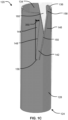
- Cylindrical tubular body 124 includes a plurality of elongated apertures 142, which may be referred to as cutter guide/blade slots or distal open ended slotted apertures, formed in and defined by the sidewall 128. As shown, the opposing sections 144, 146 of sidewall 128 define the longitudinal length of each elongated aperture 142, with section 144 of sidewall 128 located at a trailing side of elongated cutter 300 and section 146 of sidewall 128 located at a leading side of elongated cutter 300.
- section 144 of sidewall 128 terminates in am aperture trailing edge 148 which defines aperture 142 at the trailing side of elongated cutter 300, while section 146 of sidewall 128 terminates in an aperture leading edge 150 which defines aperture 142 at the leading side of elongated cutter 300.
- Leading edge 150 of the aperture 142 has a helical profile.
- the helical profile may have a pitch of 139 mm, and extend about 0.10 revolutions (10%) around the circumference (i.e. 36 degrees) of the elongated outer cutter guide 120.
- Proximal end 156 of each elongated aperture 142 is also defined by sidewall 128, which defines a proximal end width of each elongated aperture 142 between opposing longitudinal edges 148, 150.
- the distal end 158 of each elongated aperture 142 has a distal end width also defined between opposing longitudinal edges 148, 150.
- the distal end 158 is defined by the distal end opening 160 between opposing longitudinal edges 148, 150. As shown, that distal end opening 138 of passage 134 and the distal end opening 160 of elongated apertures 142 lie in the same plane transverse (perpendicular) to the center longitudinal axis A-A, and are adjacent and in contact with one another.
- the cutting end effector (expandable cutting head) 110 further comprises a cutter assembly 200.
- Cutter assembly 200 comprises a cylindrical mandrel 210, which may also be referred to as a hub, which comprises a unitary (monolithic) body having a proximal cylindrical section 212, a distal cylindrical section 214 and a conical distal end (cap) section 216.
- the cylindrical center passage 218 may be used for installation and passage of a guidewire there through during use of the device 100.
- the mandrel 210 may be mounted in a chuck (i.e. a clamp used to hold a rotating tool with radial symmetry, especially a cylinder) in a known manner.
- the proximal cylindrical section 212 has an outer diameter which substantially corresponds to the inner diameter 132 of circular tubular body 124, sized slightly smaller than the inner diameter 132 of circular tubular body 124, such that when assembled, the circular tubular body 124 is movable (e.g. slidable) proximally/distally over the cylindrical mandrel 210.
- the conical distal end section 216 has an outer diameter which nearly corresponds to the outer diameter of the circular tubular body 124, sized substantially the same, such that when assembled, the proximal end 220 of the distal end cap 220 may contact the distal end 136 of the circular tubular body 124, without being small enough to extend into the inner passage 134. While the conical distal end section 216 has (conical) face 222 is shown not to include cutter blades for simplicity, the distal end section 216 may include cutter blades 223 as shown in FIG. 1H . The distal end section 216 as shown in FIG. 1H is more fully disclosed and described in U.S. Patent Publication No. 2017/0231643 , entitled "Cutting Heads For Intramedullary Reamers".
- the distal cylindrical section 214 has an outer diameter smaller than both the outer diameter of the proximal end section 212 and the proximal end 220 of the distal end section 216.
- an annular recess 250 is formed, an inner side of which is defined in part by the cylindrical surface 224 of distal cylindrical section 214.
- Annular recess 250 is further defined by a proximal annular face 228 formed by a distal shoulder region 226 of proximal cylindrical section 212, as well as a distal annular face 238 formed by a proximal shoulder region 236 of distal end section 216 at the proximal end 220.
- Cutter assembly 200 further comprises a plurality of substantially identical elongated cutters 300 (identical, e.g. except for manufacturing tolerance). While three cutters 300 are shown, the number of cutters 300 may typically range from two cutters 300 to six cutters 300, with the circumferential space between cutter blades 302 of cutters 300 providing helical flutes for removal of cut bone and other tissue.
- cutters 300 each comprise a body having an elongated, planar cutter blade 302 and at least one mounting/connector member 330 to mount/connect the cutter 300 to the cylindrical mandrel 210.
- Cutter blade 302 comprises a proximal end 306, a distal end 308, a leading face 310 and a trailing face 312.
- Distal end 308 includes a distal end tissue cutting edge 318.
- Trailing face 312 includes a bevel 314 which narrows the thickness of the cutter blade 302 along its longitudinal length to a tissue cutting edge 320, which extends longitudinally (proximally/distally). While a single bevel 314 (i.e. only on the trailing face 312) is shown the cutter blade 302 may include a double bevel, in which both the leading face 310 and the trailing face 312 both include a bevel, or only the leading face 312 may include a bevel. As shown, the bevel angle is 45 degrees, however any suitable bevel angle may be used. The bevel angle may also be referred to as a relief angle.
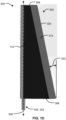
- Cutter blade 302 also tapers from the proximal end 306 to the distal end 308 at a taper angle 322, which is shown to be 20 degrees, however any suitable taper angle may be used. As shown, the width of the cutter blade 302 tapers uniformly at a constant taper angle 322 from the proximal end 306 to the distal end 308, however the cutter blade 302 may have a plurality of different taper angles 322 along the longitudinal length of the cutter blade 302.
- the at least one mounting/connector member 330 may comprise a proximal mounting/connector member 332 and a distal mounting/connector member 334.
- Proximal mounting/connector member 332 of the elongated cutter 300 connects with a mounting/connector member 230 disposed on the proximal cylindrical section 212 of the cylindrical mandrel 210, as well as on the distal cylindrical section 214 of the cylindrical mandrel 210.
- the proximal mounting/connector member 332 of the elongated cutter 300 comprises a cylindrical axle (which may also be referred to as a pivot pin), while the mounting connector/member 230 on the proximal cylindrical section 212 of the cylindrical mandrel 210 comprises a cylindrical blind bore configured to receive the cylindrical axle 332, which has a center longitudinal axis 336 extending along a length of the cylindrical axle 332.
- the cylindrical blind bore 230 of the mounting/connector member 230 configured to receive the cylindrical axle 332 of the elongated cutter 300 may be defined by a portion 232 of the cylindrical mandrel 210, shown as a mounting tab, disposed on the proximal cylindrical section 212 of the cylindrical mandrel 210, as well as on the distal cylindrical section 214 of the cylindrical mandrel 210.
- the portion 232 of the cylindrical mandrel 210 containing bore 230 may be connected to, and thus part of, the proximal cylindrical section 212 and/or the distal cylindrical section 214 of the cylindrical mandrel 210.
- the cylindrical axle 332 has a smaller diameter than the cylindrical blind bore 230 such that the cylindrical axle 332 is rotatable within the cylindrical blind bore 230.
- the cylindrical axle 332 provides an axle for rotation of the elongated cutter 300/cutter blade 302 about an elongated cutter/cutter blade rotation axis 340, which is at an angle (i.e. non-parallel or not parallel) with the center longitudinal axis A-A of the cylindrical mandrel 210 and the cutter guide 120.
- the location of the cylindrical axle 332 and the cylindrical blind bore 230 may be reversed.
- Distal mounting/connector member 334 of the elongated cutter 300 connects with a mounting connector/member 240 of the distal end section 216 of the cylindrical mandrel 210.
- the distal mounting/connector member 334 of the elongated cutter 300 comprise a cylindrical blind bore, while the mounting connector/member 240 of the distal end section 216 of the cylindrical mandrel 210 comprises a cylindrical axle 240 (which may also be referred to as a pivot pin).
- the cylindrical blind bore 334 is configured to receive the cylindrical axle 240.
- the cylindrical blind bore 334 has a larger diameter than the cylindrical axle 240 such that the cylindrical blind bore 334, and hence the elongated cutter 300, is rotatable about the cylindrical axle 240, particularly on the same axis as the cylindrical axle 332 within the cylindrical blind bore 230.
- cylindrical axle 332 also forms part of the axle for rotation of the elongated cutter 300/cutter blade 302 about an elongated cutter/cutter blade rotation axis 340.
- Cylindrical axle 240 may be press fit into a through bore 242 formed in distal end section 216.
- the location of the cylindrical axle 240 and the cylindrical blind bore 334 may be reversed.
- Proximal mounting/connector member (axle) 332 of the elongated cutter 300 may first be inserted the mounting connector/member (blind bore) 230 of the proximal cylindrical section 212 of the cylindrical mandrel 210 while tipped an angle relative to the elongated cutter/cutter blade rotation axis 340.
- the distal mounting/connector member (blind bore) 334 of the elongated cutter 300 may then be axially aligned with the through bore 242 of the distal end section 216.
- the mounting connector/member (axle) 240 may be inserted through through-bore 242 and into distal mounting/connector member (blind bore) 334 of the elongated cutter 300.
- the distal mounting/connector member (blind bore) 334 of the elongated cutter 300 has a larger diameter that the diameter of the through bore 242 of the distal end section 216 such that the mounting connector/member (axle) 240 may be press fit within through bore 242 of the distal end section 216, while still permitting the distal mounting/connector member (blind bore) 334 of the elongated cutter 300 to rotate about mounting connector/member (axle) 240 of the distal end section 216.
- each elongated cutter 300/cutter blade 302 is rotatable about its own rotation axis 340 on axle 332, 340 (which may be provided by pivot pins) of the elongated cutter 300 rotates.
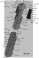
- the annular face 228 of proximal cylindrical section includes a face segment 228a provided by the distal shoulder region 226 of proximal cylindrical section 212, as well as a face segment 228b provided by portion 232 of the cylindrical mandrel 210 disposed on the proximal cylindrical section 212 of the cylindrical mandrel 210, as well as on the distal cylindrical section 214 of the cylindrical mandrel 210.
- face segment 228a provided by the distal shoulder region 226 of proximal cylindrical section 212, lies in an imaginary plane P1, which is normal (perpendicular) to the center longitudinal axis A-A.
- Face segment 228b lies in an imaginary plane P2, which is at an angle 350 (which may be referred to as the elongated cutter/cutter blade axle angle) with the imaginary plane P1, with the vertex 352 of the axle angle 350 at the intersection of the imaginary planes P1, P2.
- the elongated cutter/cutter blade axle axis 340 lies in an imaginary plane P3 normal (perpendicular) to face segment 228b.
- the center longitudinal axis A-A lies in an imaginary plane P2, which is parallel to the center longitudinal axis A-A.
- the elongated cutter/cutter blade axle axis 340 lies in an imaginary plane P1 which is at axle angle 350 with imaginary plane P2, with the vertex 352 of the axle angle 350 at the intersection of the imaginary planes P1, P2.
- the elongated cutter/cutter blade axle axis 340 maintains a substantially constant radial distance (e.g. changes 1.5 mm or less, or more particularly changes 1 mm or less) from the center longitudinal axis A-A along a longitudinal length of the cutter blade 302 from the proximal end 306 to the distal end 308.
- the axle axis 340 at the distal end 308 of the cutter blade 302 is circumferentially forward of the axle axis 340 at the proximal end 306 of the cutter blade 302 in the cutting direction, i.e. the counter-clockwise direction when the cutting end effector (expandable cutting head) 110 is viewed distally to proximally.
- each of the cutting blades 300 are arranged equally spaced circumferentially within annular recess 250 relative to the cylindrical surface 224 of distal cylindrical section 214, as well as each other. Moreover, each of the cutting blades 300 are arranged equally radially distant from the center longitudinal axis A-A of the cylindrical mandrel 210 and the cutter guide 120.
- the cutter assembly 200 may be inserted into the inner passage 134 of the tubular body 124 of the cutter guide 120, with at least a portion of each elongated cutter 300 occupying one of the elongated sidewall apertures 142, respectively (i.e. in a one-to-one relationship).
- the cutting end effector (expandable cutting head) 110 provides an expandable cutting diameter, particularly by rotating each of the elongated cutters 300/cutter blades 302 on their respective axles about their respective axle angles 350 when a position of the tubular body 124 of the cutter guide 120 is moved longitudinally, proximally or distally, along the longitudinal axis A-A. As shown in FIGS.
- the cutter assembly 200 is shown to be rotated in a counter-clockwise cutting direction when the cutting end effector (expandable cutting head) 110 is viewed distally to proximally or, alternatively, rotated in a clockwise cutting direction when cutting end effector (expandable cutting head) 110 is viewed proximally to distally.
- the leading edge 150 of the aperture 142 which again has a helical profile (which may be determined by the blade axle angle 350 and the taper angle 322), mechanically engages in contact with a leading engagement edge 316 (see FIG. 2H ) of cutter blade 302.
- the elongated cutters 300/cutter blades 302 are in their most inward/retracted position, and the elongated cutter guide 120 is in its most proximal position relative to the cutter assembly 200. Thereafter, in FIGS.
- the elongated cutter guide 120 is progressively moved distally along the longitudinal axis A-A, while the cutter assembly 200 is held stationary distally/proximally relative to the longitudinal axis A-A. Due to the contour of the leading edge 150 of the aperture 142, as the elongated cutter guide 120 is progressively moved distally along the longitudinal axis A-A, the resultant engagement contact with the leading engagement edge 316 of cutter blade 302 causes the elongated cutter 300/cutter blade 302 to rotate clockwise on rotation axis 340 (opposite the cutting direction) when viewed distally to proximally, thus increasing the cutting diameter. As shown in FIGS.
- the contour of the trailing edge 148 of the aperture 142 is parallel with the trailing face 312 of the cutter blade 302 (i.e. the trailing edge 148 of the aperture 142 is at a same angle as the blade axle angle 350) to prevent the cutter blade 302 from opening further than the desired amount, in contrast to the helix cut of the leading edge 150 to force the cutter blade 302 to extend and retract with a linear change in blade diameter.
- the elongated cutter guide 120 is progressively moved proximally along the longitudinal axis A-A, while the cutter assembly 200 is held stationary distally/proximally relative to the longitudinal axis A-A.
- the resultant mechanical engagement contact of the distal end 149 of the trailing edge 148 of the aperture 142 with the trailing face 312 of the cutter blade 302 causes the elongated cutter 300/cutter blade 302 to rotate counter-clockwise on pivot axis 340 (same direction the cutting direction) when viewed distally to proximally, thus decreasing the cutting diameter.
- the cutting/reaming diameter of a cut passage within bone may be varied, without having to replace/change the cutting end effector (expandable cutting head) 110, thus saving time.
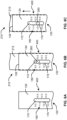
- the cutters 300 are shown positioned to form a 9.5 mm cutting/reaming diameter.
- the cutters 300 are shown positioned to form a 10.5-15.5 mm cutting/reaming diameter, in 1 mm adjustments increments.
- the adjustment increment may include any distance, such as 0.5 mm.
- the cutters 300 are shown positioned to form a 16 mm cutting/reaming diameter.
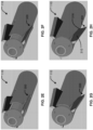
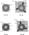
- FIG. 3A is a distal end view of the end effector (expandable cutting head) 110 with the cutters 300 in a fully inward/retracted position, while FIG. 3B shows the cutters 300 in a fully outward/extended position.
- FIG. 4A is a proximal end view of the end effector (expandable cutting head) 110 with the cutters 300 in a fully inward/retracted position, while FIG. 4B shows the cutters 300 in a fully outward/extended position.
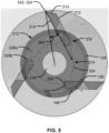
- cutter blade 302 has a positive rake angle 360, which may be understood to be the angle created between two rays (sides), with a first ray/side connecting the center longitudinal axis A-A with the outermost point 324 of the cutter blade 302 (the tangent point of the cutting diameter, which is also the vertex of the rake angle 360), and a second ray/side connecting with the outermost point 324 of the cutter blade 302 and extending parallel with the leading face 310 of the cutter blade 302.
- the rake angle 360 remains positive at various blade axle angles 350 and blade taper angles 322 for each maximum cutting diameter between 9.5 mm and 16 mm.
- an exemplary cutting end effector (expandable cutting head) 110 may have a cutting diameter which may be in a range of 9.5 mm to 16 mm.
- the axle angle 350 may be in a range of 1 degree to 10 degrees, and more particularly 4 degrees to 9 degrees.
- the cutter rotation axis 340 may extend circumferentially around the center longitudinal rotation axis A-A in a range of 1% to 15% of a full rotation around the center longitudinal rotation axis A-A.
- the blade taper angle 322 may be in a range of 8 degrees to 12 degrees.
- the blade taper angle 322 is preferably larger than the corresponding axle angle 350, particularly to allow the rake angle 360 to remain positive over the range of cutting (reaming) diameters.
- the cutting end effector (expandable cutting head) 110 of the present disclosure utilizes rotatable cutter blades which each are configured to each rotate on their own rotation axle which increases or decreases a cutting diameter of the cutting end effector (expandable cutting head) 110.
- the expandable cutting head is an expandable reamer cutting head utilizes rotatable cutter blades which each are configured to each rotate on their own rotation axle which increases or decreases a reaming diameter of the expandable reamer cutting head 110.
- each of the rotatable cutter blades is at an axle angle relative to a longitudinal axis of rotation of the expandable (reamer) cutting head, which rotation of the cutter blade about the axle angle increases or decreases a reaming diameter of the expandable (reamer) cutting head 110.
- the medical device 100/cutting end effector (expandable cutting head) 110 may include an anti-rotation mechanism 400 which inhibits the tubular body 124 of the elongated cutter guide 120 and cylindrical mandrel 210 of the cutter assembly 200 from rotating relative to one another.
- the anti-rotation mechanism 400 may comprise an elongated enclosed aperture/slot 170 formed in the tubular body 124 of the elongated cutter guide 120 which extends parallel with the center longitudinal axis A-A, which is occupied by a cylindrical pin 260 of the cylindrical mandrel 210 which extends transverse to the center longitudinal axis A-A.
- the width of the elongated enclosed aperture/slot 170 corresponds to the diameter of the cylindrical pin 260, which inhibits the tubular body 124 of the elongated cutter guide 120 and cylindrical mandrel 210 of the cutter assembly 200 from rotating relative to one another.
- the elongated aperture/slot 170 further includes a series of detents/catches 176 located along the opposing longitudinal sides of the elongated aperture/slot 170.
- the detents/catches 176 releasably lock or otherwise releasably hold the longitudinal position of the elongated cutter guide 120 and cylindrical mandrel 210 relative to one another and. more particularly hold the longitudinal position of the elongated cutter guide 120 and cylindrical mandrel 210 relative to one another in a series of incremental (stepped) positions relative to one another.
- the anti-rotation mechanism may also similarly be a releasable locking/retaining mechanism.
- the position of the pin 260 may change within the aperture/slot 170 from a first releasably fixed position to a second releasably fixed position.
- the detents/catches 176 and/or the pin 260 may resiliently (elastically) deform to enable the pin 260 to travel within aperture/slot 170.
- the tubular body 124 of the elongated cutter guide 120 may include indicia 180, such as numbers or letters.
- the indicia 180 may represent the various cutter diameters which are available with the medical device 100/cutting end effector (expandable cutting head) 110.
- the tubular body 124 of the elongated cutter guide 120 is moved distally relative to the cutter assembly 200/cylindrical mandrel 210, as shown in FIG. 6B to FIG. 6C , the cutting diameter is indicated has having changed from 10.5 mm to 13.5 mm.
- the anti-rotation mechanism and a releasable locking/retaining mechanism may also be considered a positional feedback/indicator mechanism for the set diameter of the cutting blades 300.
- the cutting end effector (expandable cutting head) 110 may be coupled to a flexible drill shaft 500, and more particularly the mandrel 210 may be directly rotateably coupled to the flexible drill shaft 500 with the elongated cutter guide 120 overlying the coupling, which is coupled to a rotary device (drill) 600, through which a guide wire 700 may be extended.
- a range includes each individual member.
- a group having 1-3 configurations refers to groups having 1, 2, or 3 configurations.
- a group having 1-5 configurations refers to groups having 1, 2, 3, 4, or 5 configurations, and so forth.
Landscapes
- Health & Medical Sciences (AREA)
- Surgery (AREA)
- Life Sciences & Earth Sciences (AREA)
- Biomedical Technology (AREA)
- Medical Informatics (AREA)
- Orthopedic Medicine & Surgery (AREA)
- Oral & Maxillofacial Surgery (AREA)
- Engineering & Computer Science (AREA)
- Dentistry (AREA)
- Heart & Thoracic Surgery (AREA)
- Nuclear Medicine, Radiotherapy & Molecular Imaging (AREA)
- Molecular Biology (AREA)
- Animal Behavior & Ethology (AREA)
- General Health & Medical Sciences (AREA)
- Public Health (AREA)
- Veterinary Medicine (AREA)
- Surgical Instruments (AREA)
Claims (13)
- Medizinische Vorrichtung (100) zur Verwendung in orthopädischen chirurgischen Verfahren zum Ausschneiden von Gewebe z.B. Knochen, umfassend:einen drehbaren Schneidkopf (119) mit einer zentralen Längsdrehachse;wobei der drehbare Messerkopf einen Dorn (210) und eine Vielzahl vonlänglichen Messern (300) umfasst, die auf dem Dorn (210) angeordnet sind;wobei jedes der Messer (300) eine Messerklinge (302) umfasst;jedes der länglichen Messer (300) um eine Messerdrehachse (340) drehbar ist, wobei die Drehung jedes der länglichen Messer (300) um die Messerdrehachse (340) einen Schneiddurchmesser des drehbaren Messerkopfes (119) verändert;dadurch gekennzeichnet, dassjede Messerdrehachse (340) eine Länge aufweist, die sich gleichzeitig sowohl in Längsrichtung entlang der mittleren Längsdrehachse (A-A) als auch in Umfangsrichtung um die mittlere Längsdrehachse (A-A) erstreckt, so dass die Messerdrehachse (340) an einem distalen Ende (308) der Schneidklinge (302) in Umfangsrichtung der Messerdrehachse (340) im Gegenuhrzeigersinn vor einem proximalen Ende (306) der Schneidklinge (302) ist, wenn der Schneidkopf (110) von distal nach proximal betrachtet wird; und jede der Messerdrehachsen (340) parallel zu einer ersten imaginären Ebene (P1) ist, die sich jeweils in einem Winkel (350) zu einer zweiten imaginären Ebene (P2) erstreckt, die sich parallel zu der mittleren Längsachse (A-A) erstreckt.
- Die medizinische Vorrichtung (100) nach Anspruch 1, wobei:
der Dorn (210) einen proximalen zylindrischen Abschnitt (212), einen distalen zylindrischen Abschnitt (214) und einen distalen Endabschnitt (216) umfasst;wobei der distale zylindrische Abschnitt (214) distal von dem proximalen zylindrischen Abschnitt (212) angeordnet ist und der distale Endabschnitt (216) distal von dem distalen zylindrischen Abschnitt (214) angeordnet ist;wobei der distale zylindrische Abschnitt (214) einen Außendurchmesser hat, der kleiner ist als ein Außendurchmesser des proximalen zylindrischen Abschnitts (212) und des distalen Endabschnitts (216), so, dass eine ringförmige Aussparung zwischen dem proximalen zylindrischen Abschnitt (212) und dem distalen Endabschnitt (216) gebildet wird;wobei jede der länglichen Messer (300) in der ringförmigen Ausnehmung angeordnet ist, und wobei der distale Endabschnitt (216) des Dorns (210) vorzugsweise konisch geformt ist und/oder eine Vielzahl von Schneidklingen (302) aufweist. - Die medizinische Vorrichtung (100) nach Anspruch 1, wobei:jedes der länglichen Messer (300) über eine in einer Bohrung (230) drehbare Achse (332) um die Messerdrehachse (340) drehbar ist,wobei jede der länglichen Messer (300) vorzugsweise die Achse (332) aufweist und jede der Bohrungen (230) vorzugsweise im Dorn (210) angeordnet ist.
- Die medizinische Vorrichtung (100) nach Anspruch 3, wobei:der Dorn (210) einen proximalen zylindrischen Abschnitt (212), einen distalen zylindrischen Abschnitt (214) und einen distalen Endabschnitt (216) umfasst;wobei der distale zylindrische Abschnitt (214) distal von dem proximalen zylindrischen Abschnitt (212) angeordnet ist und der distale Endabschnitt (216) distal von dem distalen zylindrischen Abschnitt (214) angeordnet ist;wobei der distale zylindrische Abschnitt (214) einen Außendurchmesser hat, der kleiner ist als ein Außendurchmesser des proximalen zylindrischen Abschnitts (212) und des distalen Endabschnitts (216), so, dass eine ringförmige Aussparung zwischen dem proximalen zylindrischen Abschnitt (212) und dem distalen Endabschnitt (216) gebildet wird;wobei jedes der länglichen Messer (300) in der ringförmigen Aussparung angeordnet ist; und wobei jede der Bohrungen (230) in einem Abschnitt des Dorns (210) angeordnet ist, der Teil des proximalen zylindrischen Abschnitts (212) und/oder des distalen zylindrischen Abschnitts (214) ist.
- Die medizinische Vorrichtung (100) nach Anspruch 4, wobei:der Teil des Dorns (210), der Teil des proximalen zylindrischen Abschnitts (210) ist und/oder der distale zylindrische Abschnitt (214) des Dorns (210) eine Befestigungslasche (232) umfassen;wobei die Befestigungslasche (232) vorzugsweise neben einem Schulterbereich (226) des proximalen zylindrischen Abschnitts (212) angeordnet ist.
- Die medizinische Vorrichtung (100) nach Anspruch 1, wobei:
jedes der langgestreckten Messer (300) über eine um eine Achse (240) drehbare Bohrung (334) um die Messerdrehachse (340) drehbar ist, wobei jedes der langgestreckten Messer (300) vorzugsweise die Bohrung (334) aufweist und jede der Achsen (340) sich vorzugsweise von dem Dorn (210) aus und in jede der Bohrungen (340) erstreckt. - Die medizinische Vorrichtung (100) nach Anspruch 6, wobei:
der Dorn (210) einen proximalen zylindrischen Abschnitt (212), einen distalen zylindrischen Abschnitt (214) und einen distalen Endabschnitt (216) umfasst;wobei der distale zylindrische Abschnitt (216) distal von dem proximalen zylindrischen Abschnitt (212) angeordnet ist und der distale Endabschnitt (216) distal von dem distalen zylindrischen Abschnitt (214) angeordnet ist;wobei der distale zylindrische Abschnitt (214) einen Außendurchmesser hat, der kleiner ist als ein Außendurchmesser des proximalen zylindrischen Abschnitts (212) und des distalen Endabschnitts (216), so, dass eine ringförmige Ausnehmung zwischen dem proximalen zylindrischen Abschnitt (212) und dem distalen Endabschnitt (216) gebildet wird;wobei jede der länglichen Messer (300) in der ringförmigen Aussparung angeordnet ist; und wobei jede der Achsen (240) sich von einer Bohrung (242) erstreckt, die in dem distalen Endabschnitt (216) des Dorns (210) ausgebildet ist. - Die medizinische Vorrichtung (100) nach Anspruch 1, wobei:der drehbare Messerkopf (110) ferner eine längliche Messerführung (120) umfasst, wobei die längliche Messerführung (120) einen rohrförmigen Körper (124) aufweist, der mechanisch mit den länglichen Messern (300) in Eingriff steht; undwobei jedes der langgestreckten Messer (300) durch Bewegung (340) des rohrförmigen Körpers (124) entlang der Längsdrehachse (A-A) relativ zu den langgestreckten Schneidwerkzeugen (300) um die Messerdrehachse drehbar ist.
- Die medizinische Vorrichtung (100) nach Anspruch 8, wobei:der rohrförmige Körper (124) und die länglichen Messer (300) so angeordnet sind, dass eine distale Bewegung des rohrförmigen Körpers (124) entlang der Längsdrehachse (A-A) relativ zu den länglichen Messern (300) den Schneiddurchmesser des drehbaren Schneidkopfes (110) vergrößert; undder rohrförmige Körper (124) und die länglichen Messer (300) so angeordnet sind, dass eine proximale Bewegung des rohrförmigen Körpers (124) entlang der Längsdrehachse (A-A) relativ zu den länglichen Messern (300) den Schneiddurchmesser des drehbaren Messerkopfes (110) verringert.
- Die medizinische Vorrichtung (100) nach Anspruch 8, wobei:
der rohrförmige Körper (124) eine Vielzahl von Messerführungsschlitzen (124) umfasst; und wobei jedes der länglichen Messer (300) einen der Messerführungsschlitze (124) besetzt. - Die medizinische Vorrichtung (100) nach Anspruch 10, wobei:jeder der Messerführungsschlitze (124) durch gegenüberliegende Kanten (148, 50) des rohrförmigen Körpers (124) definiert wird;wobei die gegenüberliegenden Kanten (148, 50), die jeden der Messerführungsschlitze (124) definieren, eine Vorderkante (150) aufweisen, die das längliche Schneidwerkzeug (300), das den Schlitz (124) einnimmt, in einer Rotationsschneidrichtung des drehbaren Messerkopfes (110) führt, und eine Hinterkante (148) aufweisen, die dem länglichen Messer (300), das den Messerführungsschlitz (124) einnimmt, in einer Rotationsschneidrichtung des drehbaren Messerkopfes (110) nachläuft;wobei die Vorderkante (150) des rohrförmigen Körpers (124), die jeden Messerführungsschlitz (124) definiert, mechanisch in das längliche Schneidwerkzeug (300) eingreift, das den Messerführungsschlitz (124) besetzt, um den Schneiddurchmesser des drehbaren Schneidkopfes (110) zu vergrößern; undwobei die Hinterkante (148) des rohrförmigen Körpers (124), die jeden Messerführungsschlitz (124) definiert, mechanisch mit dem länglichen Messer (300), das den Messerführungsschlitz (124) besetzt, in Eingriff kommt, um den Schneiddurchmesser des drehbaren Messerkopfes (110) zu verringern.
- Das medizinische Gerät (100) nach Anspruch 1, wobei:
jedes der langgestreckten Messer (300) jeweils eine langgestreckte, ebene Schneidklinge (302) umfasst; und jede der langgestreckten, ebenen Schneidklingen (302) sich vom proximalen Ende (306) zum distalen Ende (308) unter einem Verjüngungswinkel (322) verjüngt;
wobei jede der länglichen Schneidklingen (302) vorzugsweise eine vordere Fläche (310) und eine hintere Fläche (312) relativ zu einer Schneidrichtung des drehbaren Schneidkopfes (110) aufweist und wobei die hintere Fläche (312) jeder der länglichen Schneidklingen (302) vorzugsweise eine Fase (314) aufweist. - Das medizinische Gerät (100) nach Anspruch 1, wobei:
der Dorn (210) einen Durchgang (218) aufweist, der sich entlang der Längsdrehachse (A-A) erstreckt.
Applications Claiming Priority (2)
| Application Number | Priority Date | Filing Date | Title |
|---|---|---|---|
| US201862639053P | 2018-03-06 | 2018-03-06 | |
| PCT/US2019/021006 WO2019173509A1 (en) | 2018-03-06 | 2019-03-06 | Expandable reamer cutting head |
Publications (3)
| Publication Number | Publication Date |
|---|---|
| EP3745970A1 EP3745970A1 (de) | 2020-12-09 |
| EP3745970A4 EP3745970A4 (de) | 2021-11-24 |
| EP3745970B1 true EP3745970B1 (de) | 2023-08-23 |
Family
ID=67844145
Family Applications (1)
| Application Number | Title | Priority Date | Filing Date |
|---|---|---|---|
| EP19763849.7A Active EP3745970B1 (de) | 2018-03-06 | 2019-03-06 | Schneidkopf einer expandierbaren reibahle |
Country Status (3)
| Country | Link |
|---|---|
| US (1) | US11083470B2 (de) |
| EP (1) | EP3745970B1 (de) |
| WO (1) | WO2019173509A1 (de) |
Families Citing this family (3)
| Publication number | Priority date | Publication date | Assignee | Title |
|---|---|---|---|---|
| US20220022866A1 (en) * | 2020-07-21 | 2022-01-27 | Covidien Lp | Cartridge alignment mechanism for use with surgical devices |
| US20220331060A1 (en) * | 2021-04-16 | 2022-10-20 | Chia-Liang Tseng | Dental drill |
| CN114305590B (zh) * | 2022-03-16 | 2022-06-21 | 北京华脉泰科医疗器械股份有限公司 | 远端保护器 |
Family Cites Families (14)
| Publication number | Priority date | Publication date | Assignee | Title |
|---|---|---|---|---|
| US2385999A (en) | 1944-11-18 | 1945-10-02 | Hugh E Mccallion | Expanding reamer |
| US6224604B1 (en) | 1999-07-30 | 2001-05-01 | Loubert Suddaby | Expandable orthopedic drill for vertebral interbody fusion techniques |
| US6383188B2 (en) | 2000-02-15 | 2002-05-07 | The Spineology Group Llc | Expandable reamer |
| WO2002062226A1 (en) * | 2001-02-05 | 2002-08-15 | Tyco Healthcare Group Lp | Biopsy apparatus and method |
| US7608076B2 (en) | 2005-04-29 | 2009-10-27 | Greatbatch Medical S.A. | Minimally invasive collapsible surgical reamer |
| US9186170B2 (en) * | 2008-06-05 | 2015-11-17 | Cardiovascular Systems, Inc. | Bidirectional expandable head for rotational atherectomy device |
| US20120070244A1 (en) * | 2009-02-19 | 2012-03-22 | Izhak Stern Y.D.E. Engineers Ltd. | Nibbling Mechanism for Construction Material |
| US20110251616A1 (en) | 2010-04-12 | 2011-10-13 | K2M, Inc. | Expandable reamer and method of use |
| BR122020008361B1 (pt) | 2013-04-24 | 2022-06-14 | T.A.G. Medical Devices - Agriculture Cooperative Ltd | Dispositivo para remoção de material ósseo |
| JP6352642B2 (ja) * | 2013-12-03 | 2018-07-04 | 川澄化学工業株式会社 | 血管内異物除去用カテーテル |
| US9517076B2 (en) | 2014-03-11 | 2016-12-13 | Lenkbar, Llc | Reaming instrument with adjustable profile |
| EP4233741B1 (de) * | 2014-10-19 | 2025-10-08 | T.A.G. Medical Products Corporation Ltd. | Set aus führungssystem und vorrichtung zur entfernung von knochengewebe |
| EP3205294B1 (de) | 2016-02-12 | 2024-02-14 | Greatbatch Ltd. | Schneidköpfe für intramedulläre reamer |
| EP3496630B1 (de) * | 2016-08-14 | 2024-01-17 | Greatbatch Ltd. | Schneidköpfe für einen intramedullären reamer |
-
2019
- 2019-03-06 EP EP19763849.7A patent/EP3745970B1/de active Active
- 2019-03-06 US US16/294,606 patent/US11083470B2/en active Active
- 2019-03-06 WO PCT/US2019/021006 patent/WO2019173509A1/en not_active Ceased
Also Published As
| Publication number | Publication date |
|---|---|
| US11083470B2 (en) | 2021-08-10 |
| EP3745970A4 (de) | 2021-11-24 |
| WO2019173509A1 (en) | 2019-09-12 |
| US20190274694A1 (en) | 2019-09-12 |
| EP3745970A1 (de) | 2020-12-09 |
Similar Documents
| Publication | Publication Date | Title |
|---|---|---|
| US11877756B2 (en) | Systems and methods for decorticating the sacroiliac joint | |
| US7611515B2 (en) | Orthopaedic reamer driver for minimally invasive surgery | |
| US6918914B2 (en) | Minimally invasive adjustable acetubular reamer | |
| US7981031B2 (en) | Surgical access devices and methods of minimally invasive surgery | |
| US7828804B2 (en) | Transpedicular intervertebral disk access methods and devices | |
| US7641658B2 (en) | Transpedicular intervertebral disk access methods and devices | |
| DE60311289T2 (de) | Fräsvorrichtung | |
| EP1535579A2 (de) | Expandierbare Reibahle | |
| US20110251616A1 (en) | Expandable reamer and method of use | |
| US7473254B2 (en) | Pivoting bone reamer for minimally invasive joint surgery | |
| EP3745970B1 (de) | Schneidkopf einer expandierbaren reibahle | |
| US20070208228A1 (en) | Surgical retractors and methods of minimally invasive surgery | |
| US20130165935A1 (en) | Expandable retrograde drill | |
| US11234716B2 (en) | Methods and apparatus for performing discectomy | |
| US12318087B2 (en) | Vertebral disc auger | |
| US7918856B2 (en) | Guided reamer system for reshaping bone | |
| CN119896510A (zh) | 一种可变径的骨钻套件 |
Legal Events
| Date | Code | Title | Description |
|---|---|---|---|
| STAA | Information on the status of an ep patent application or granted ep patent |
Free format text: STATUS: THE INTERNATIONAL PUBLICATION HAS BEEN MADE |
|
| PUAI | Public reference made under article 153(3) epc to a published international application that has entered the european phase |
Free format text: ORIGINAL CODE: 0009012 |
|
| STAA | Information on the status of an ep patent application or granted ep patent |
Free format text: STATUS: REQUEST FOR EXAMINATION WAS MADE |
|
| 17P | Request for examination filed |
Effective date: 20200902 |
|
| AK | Designated contracting states |
Kind code of ref document: A1 Designated state(s): AL AT BE BG CH CY CZ DE DK EE ES FI FR GB GR HR HU IE IS IT LI LT LU LV MC MK MT NL NO PL PT RO RS SE SI SK SM TR |
|
| AX | Request for extension of the european patent |
Extension state: BA ME |
|
| DAV | Request for validation of the european patent (deleted) | ||
| DAX | Request for extension of the european patent (deleted) | ||
| A4 | Supplementary search report drawn up and despatched |
Effective date: 20211025 |
|
| RIC1 | Information provided on ipc code assigned before grant |
Ipc: A61B 17/16 20060101ALI20211019BHEP Ipc: A61B 17/3207 20060101AFI20211019BHEP |
|
| GRAP | Despatch of communication of intention to grant a patent |
Free format text: ORIGINAL CODE: EPIDOSNIGR1 |
|
| STAA | Information on the status of an ep patent application or granted ep patent |
Free format text: STATUS: GRANT OF PATENT IS INTENDED |
|
| INTG | Intention to grant announced |
Effective date: 20230404 |
|
| GRAS | Grant fee paid |
Free format text: ORIGINAL CODE: EPIDOSNIGR3 |
|
| GRAA | (expected) grant |
Free format text: ORIGINAL CODE: 0009210 |
|
| STAA | Information on the status of an ep patent application or granted ep patent |
Free format text: STATUS: THE PATENT HAS BEEN GRANTED |
|
| AK | Designated contracting states |
Kind code of ref document: B1 Designated state(s): AL AT BE BG CH CY CZ DE DK EE ES FI FR GB GR HR HU IE IS IT LI LT LU LV MC MK MT NL NO PL PT RO RS SE SI SK SM TR |
|
| REG | Reference to a national code |
Ref country code: GB Ref legal event code: FG4D |
|
| REG | Reference to a national code |
Ref country code: CH Ref legal event code: EP |
|
| REG | Reference to a national code |
Ref country code: DE Ref legal event code: R096 Ref document number: 602019035650 Country of ref document: DE |
|
| REG | Reference to a national code |
Ref country code: IE Ref legal event code: FG4D |
|
| REG | Reference to a national code |
Ref country code: LT Ref legal event code: MG9D |
|
| REG | Reference to a national code |
Ref country code: NL Ref legal event code: MP Effective date: 20230823 |
|
| REG | Reference to a national code |
Ref country code: DE Ref legal event code: R082 Ref document number: 602019035650 Country of ref document: DE Representative=s name: LIPPERT STACHOW PATENTANWAELTE RECHTSANWAELTE , DE |
|
| REG | Reference to a national code |
Ref country code: AT Ref legal event code: MK05 Ref document number: 1601651 Country of ref document: AT Kind code of ref document: T Effective date: 20230823 |
|
| PG25 | Lapsed in a contracting state [announced via postgrant information from national office to epo] |
Ref country code: GR Free format text: LAPSE BECAUSE OF FAILURE TO SUBMIT A TRANSLATION OF THE DESCRIPTION OR TO PAY THE FEE WITHIN THE PRESCRIBED TIME-LIMIT Effective date: 20231124 |
|
| PG25 | Lapsed in a contracting state [announced via postgrant information from national office to epo] |
Ref country code: IS Free format text: LAPSE BECAUSE OF FAILURE TO SUBMIT A TRANSLATION OF THE DESCRIPTION OR TO PAY THE FEE WITHIN THE PRESCRIBED TIME-LIMIT Effective date: 20231223 |
|
| PG25 | Lapsed in a contracting state [announced via postgrant information from national office to epo] |
Ref country code: SE Free format text: LAPSE BECAUSE OF FAILURE TO SUBMIT A TRANSLATION OF THE DESCRIPTION OR TO PAY THE FEE WITHIN THE PRESCRIBED TIME-LIMIT Effective date: 20230823 Ref country code: RS Free format text: LAPSE BECAUSE OF FAILURE TO SUBMIT A TRANSLATION OF THE DESCRIPTION OR TO PAY THE FEE WITHIN THE PRESCRIBED TIME-LIMIT Effective date: 20230823 Ref country code: PT Free format text: LAPSE BECAUSE OF FAILURE TO SUBMIT A TRANSLATION OF THE DESCRIPTION OR TO PAY THE FEE WITHIN THE PRESCRIBED TIME-LIMIT Effective date: 20231226 Ref country code: NO Free format text: LAPSE BECAUSE OF FAILURE TO SUBMIT A TRANSLATION OF THE DESCRIPTION OR TO PAY THE FEE WITHIN THE PRESCRIBED TIME-LIMIT Effective date: 20231123 Ref country code: NL Free format text: LAPSE BECAUSE OF FAILURE TO SUBMIT A TRANSLATION OF THE DESCRIPTION OR TO PAY THE FEE WITHIN THE PRESCRIBED TIME-LIMIT Effective date: 20230823 Ref country code: LV Free format text: LAPSE BECAUSE OF FAILURE TO SUBMIT A TRANSLATION OF THE DESCRIPTION OR TO PAY THE FEE WITHIN THE PRESCRIBED TIME-LIMIT Effective date: 20230823 Ref country code: LT Free format text: LAPSE BECAUSE OF FAILURE TO SUBMIT A TRANSLATION OF THE DESCRIPTION OR TO PAY THE FEE WITHIN THE PRESCRIBED TIME-LIMIT Effective date: 20230823 Ref country code: IS Free format text: LAPSE BECAUSE OF FAILURE TO SUBMIT A TRANSLATION OF THE DESCRIPTION OR TO PAY THE FEE WITHIN THE PRESCRIBED TIME-LIMIT Effective date: 20231223 Ref country code: HR Free format text: LAPSE BECAUSE OF FAILURE TO SUBMIT A TRANSLATION OF THE DESCRIPTION OR TO PAY THE FEE WITHIN THE PRESCRIBED TIME-LIMIT Effective date: 20230823 Ref country code: GR Free format text: LAPSE BECAUSE OF FAILURE TO SUBMIT A TRANSLATION OF THE DESCRIPTION OR TO PAY THE FEE WITHIN THE PRESCRIBED TIME-LIMIT Effective date: 20231124 Ref country code: FI Free format text: LAPSE BECAUSE OF FAILURE TO SUBMIT A TRANSLATION OF THE DESCRIPTION OR TO PAY THE FEE WITHIN THE PRESCRIBED TIME-LIMIT Effective date: 20230823 Ref country code: AT Free format text: LAPSE BECAUSE OF FAILURE TO SUBMIT A TRANSLATION OF THE DESCRIPTION OR TO PAY THE FEE WITHIN THE PRESCRIBED TIME-LIMIT Effective date: 20230823 |
|
| PG25 | Lapsed in a contracting state [announced via postgrant information from national office to epo] |
Ref country code: PL Free format text: LAPSE BECAUSE OF FAILURE TO SUBMIT A TRANSLATION OF THE DESCRIPTION OR TO PAY THE FEE WITHIN THE PRESCRIBED TIME-LIMIT Effective date: 20230823 |
|
| PG25 | Lapsed in a contracting state [announced via postgrant information from national office to epo] |
Ref country code: ES Free format text: LAPSE BECAUSE OF FAILURE TO SUBMIT A TRANSLATION OF THE DESCRIPTION OR TO PAY THE FEE WITHIN THE PRESCRIBED TIME-LIMIT Effective date: 20230823 |
|
| PG25 | Lapsed in a contracting state [announced via postgrant information from national office to epo] |
Ref country code: SM Free format text: LAPSE BECAUSE OF FAILURE TO SUBMIT A TRANSLATION OF THE DESCRIPTION OR TO PAY THE FEE WITHIN THE PRESCRIBED TIME-LIMIT Effective date: 20230823 Ref country code: RO Free format text: LAPSE BECAUSE OF FAILURE TO SUBMIT A TRANSLATION OF THE DESCRIPTION OR TO PAY THE FEE WITHIN THE PRESCRIBED TIME-LIMIT Effective date: 20230823 Ref country code: ES Free format text: LAPSE BECAUSE OF FAILURE TO SUBMIT A TRANSLATION OF THE DESCRIPTION OR TO PAY THE FEE WITHIN THE PRESCRIBED TIME-LIMIT Effective date: 20230823 Ref country code: EE Free format text: LAPSE BECAUSE OF FAILURE TO SUBMIT A TRANSLATION OF THE DESCRIPTION OR TO PAY THE FEE WITHIN THE PRESCRIBED TIME-LIMIT Effective date: 20230823 Ref country code: DK Free format text: LAPSE BECAUSE OF FAILURE TO SUBMIT A TRANSLATION OF THE DESCRIPTION OR TO PAY THE FEE WITHIN THE PRESCRIBED TIME-LIMIT Effective date: 20230823 Ref country code: CZ Free format text: LAPSE BECAUSE OF FAILURE TO SUBMIT A TRANSLATION OF THE DESCRIPTION OR TO PAY THE FEE WITHIN THE PRESCRIBED TIME-LIMIT Effective date: 20230823 Ref country code: SK Free format text: LAPSE BECAUSE OF FAILURE TO SUBMIT A TRANSLATION OF THE DESCRIPTION OR TO PAY THE FEE WITHIN THE PRESCRIBED TIME-LIMIT Effective date: 20230823 |
|
| REG | Reference to a national code |
Ref country code: DE Ref legal event code: R097 Ref document number: 602019035650 Country of ref document: DE |
|
| PG25 | Lapsed in a contracting state [announced via postgrant information from national office to epo] |
Ref country code: IT Free format text: LAPSE BECAUSE OF FAILURE TO SUBMIT A TRANSLATION OF THE DESCRIPTION OR TO PAY THE FEE WITHIN THE PRESCRIBED TIME-LIMIT Effective date: 20230823 |
|
| PLBE | No opposition filed within time limit |
Free format text: ORIGINAL CODE: 0009261 |
|
| STAA | Information on the status of an ep patent application or granted ep patent |
Free format text: STATUS: NO OPPOSITION FILED WITHIN TIME LIMIT |
|
| 26N | No opposition filed |
Effective date: 20240524 |
|
| PG25 | Lapsed in a contracting state [announced via postgrant information from national office to epo] |
Ref country code: SI Free format text: LAPSE BECAUSE OF FAILURE TO SUBMIT A TRANSLATION OF THE DESCRIPTION OR TO PAY THE FEE WITHIN THE PRESCRIBED TIME-LIMIT Effective date: 20230823 |
|
| P01 | Opt-out of the competence of the unified patent court (upc) registered |
Free format text: CASE NUMBER: APP_40135/2024 Effective date: 20240705 |
|
| PG25 | Lapsed in a contracting state [announced via postgrant information from national office to epo] |
Ref country code: BG Free format text: LAPSE BECAUSE OF FAILURE TO SUBMIT A TRANSLATION OF THE DESCRIPTION OR TO PAY THE FEE WITHIN THE PRESCRIBED TIME-LIMIT Effective date: 20230823 |
|
| PG25 | Lapsed in a contracting state [announced via postgrant information from national office to epo] |
Ref country code: LU Free format text: LAPSE BECAUSE OF NON-PAYMENT OF DUE FEES Effective date: 20240306 |
|
| PG25 | Lapsed in a contracting state [announced via postgrant information from national office to epo] |
Ref country code: MC Free format text: LAPSE BECAUSE OF FAILURE TO SUBMIT A TRANSLATION OF THE DESCRIPTION OR TO PAY THE FEE WITHIN THE PRESCRIBED TIME-LIMIT Effective date: 20230823 |
|
| PG25 | Lapsed in a contracting state [announced via postgrant information from national office to epo] |
Ref country code: MC Free format text: LAPSE BECAUSE OF FAILURE TO SUBMIT A TRANSLATION OF THE DESCRIPTION OR TO PAY THE FEE WITHIN THE PRESCRIBED TIME-LIMIT Effective date: 20230823 Ref country code: LU Free format text: LAPSE BECAUSE OF NON-PAYMENT OF DUE FEES Effective date: 20240306 Ref country code: BG Free format text: LAPSE BECAUSE OF FAILURE TO SUBMIT A TRANSLATION OF THE DESCRIPTION OR TO PAY THE FEE WITHIN THE PRESCRIBED TIME-LIMIT Effective date: 20230823 |
|
| REG | Reference to a national code |
Ref country code: BE Ref legal event code: MM Effective date: 20240331 |
|
| PG25 | Lapsed in a contracting state [announced via postgrant information from national office to epo] |
Ref country code: BE Free format text: LAPSE BECAUSE OF NON-PAYMENT OF DUE FEES Effective date: 20240331 |
|
| PG25 | Lapsed in a contracting state [announced via postgrant information from national office to epo] |
Ref country code: IE Free format text: LAPSE BECAUSE OF NON-PAYMENT OF DUE FEES Effective date: 20240306 |
|
| PG25 | Lapsed in a contracting state [announced via postgrant information from national office to epo] |
Ref country code: IE Free format text: LAPSE BECAUSE OF NON-PAYMENT OF DUE FEES Effective date: 20240306 Ref country code: BE Free format text: LAPSE BECAUSE OF NON-PAYMENT OF DUE FEES Effective date: 20240331 |
|
| PGFP | Annual fee paid to national office [announced via postgrant information from national office to epo] |
Ref country code: CH Payment date: 20250401 Year of fee payment: 7 |
|
| PG25 | Lapsed in a contracting state [announced via postgrant information from national office to epo] |
Ref country code: CY Free format text: LAPSE BECAUSE OF FAILURE TO SUBMIT A TRANSLATION OF THE DESCRIPTION OR TO PAY THE FEE WITHIN THE PRESCRIBED TIME-LIMIT; INVALID AB INITIO Effective date: 20190306 |
|
| PG25 | Lapsed in a contracting state [announced via postgrant information from national office to epo] |
Ref country code: HU Free format text: LAPSE BECAUSE OF FAILURE TO SUBMIT A TRANSLATION OF THE DESCRIPTION OR TO PAY THE FEE WITHIN THE PRESCRIBED TIME-LIMIT; INVALID AB INITIO Effective date: 20190306 |
|
| PG25 | Lapsed in a contracting state [announced via postgrant information from national office to epo] |
Ref country code: TR Free format text: LAPSE BECAUSE OF FAILURE TO SUBMIT A TRANSLATION OF THE DESCRIPTION OR TO PAY THE FEE WITHIN THE PRESCRIBED TIME-LIMIT Effective date: 20230823 |
|
| PGFP | Annual fee paid to national office [announced via postgrant information from national office to epo] |
Ref country code: FR Payment date: 20251231 Year of fee payment: 8 |
|
| REG | Reference to a national code |
Ref country code: CH Ref legal event code: U11 Free format text: ST27 STATUS EVENT CODE: U-0-0-U10-U11 (AS PROVIDED BY THE NATIONAL OFFICE) Effective date: 20260401 |
|
| PGFP | Annual fee paid to national office [announced via postgrant information from national office to epo] |
Ref country code: GB Payment date: 20260106 Year of fee payment: 8 |
|
| PGFP | Annual fee paid to national office [announced via postgrant information from national office to epo] |
Ref country code: DE Payment date: 20260102 Year of fee payment: 8 |