EP3746332B1 - Scheinwerferanordnung für zweirad - Google Patents
Scheinwerferanordnung für zweirad Download PDFInfo
- Publication number
- EP3746332B1 EP3746332B1 EP19746856.4A EP19746856A EP3746332B1 EP 3746332 B1 EP3746332 B1 EP 3746332B1 EP 19746856 A EP19746856 A EP 19746856A EP 3746332 B1 EP3746332 B1 EP 3746332B1
- Authority
- EP
- European Patent Office
- Prior art keywords
- light
- signal
- headlight assembly
- light source
- intensity
- Prior art date
- Legal status (The legal status is an assumption and is not a legal conclusion. Google has not performed a legal analysis and makes no representation as to the accuracy of the status listed.)
- Active
Links
Images


Classifications
-
- B—PERFORMING OPERATIONS; TRANSPORTING
- B60—VEHICLES IN GENERAL
- B60Q—ARRANGEMENT OF SIGNALLING OR LIGHTING DEVICES, THE MOUNTING OR SUPPORTING THEREOF OR CIRCUITS THEREFOR, FOR VEHICLES IN GENERAL
- B60Q1/00—Arrangement of optical signalling or lighting devices, the mounting or supporting thereof or circuits therefor
- B60Q1/02—Arrangement of optical signalling or lighting devices, the mounting or supporting thereof or circuits therefor the devices being primarily intended to illuminate the way ahead or to illuminate other areas of way or environments
- B60Q1/04—Arrangement of optical signalling or lighting devices, the mounting or supporting thereof or circuits therefor the devices being primarily intended to illuminate the way ahead or to illuminate other areas of way or environments the devices being headlights
- B60Q1/14—Arrangement of optical signalling or lighting devices, the mounting or supporting thereof or circuits therefor the devices being primarily intended to illuminate the way ahead or to illuminate other areas of way or environments the devices being headlights having dimming means
- B60Q1/1415—Dimming circuits
- B60Q1/1423—Automatic dimming circuits, i.e. switching between high beam and low beam due to change of ambient light or light level in road traffic
- B60Q1/143—Automatic dimming circuits, i.e. switching between high beam and low beam due to change of ambient light or light level in road traffic combined with another condition, e.g. using vehicle recognition from camera images or activation of wipers
-
- B—PERFORMING OPERATIONS; TRANSPORTING
- B60—VEHICLES IN GENERAL
- B60Q—ARRANGEMENT OF SIGNALLING OR LIGHTING DEVICES, THE MOUNTING OR SUPPORTING THEREOF OR CIRCUITS THEREFOR, FOR VEHICLES IN GENERAL
- B60Q1/00—Arrangement of optical signalling or lighting devices, the mounting or supporting thereof or circuits therefor
- B60Q1/0029—Spatial arrangement
- B60Q1/0041—Spatial arrangement of several lamps in relation to each other
-
- B—PERFORMING OPERATIONS; TRANSPORTING
- B60—VEHICLES IN GENERAL
- B60Q—ARRANGEMENT OF SIGNALLING OR LIGHTING DEVICES, THE MOUNTING OR SUPPORTING THEREOF OR CIRCUITS THEREFOR, FOR VEHICLES IN GENERAL
- B60Q1/00—Arrangement of optical signalling or lighting devices, the mounting or supporting thereof or circuits therefor
- B60Q1/0017—Devices integrating an element dedicated to another function
- B60Q1/0023—Devices integrating an element dedicated to another function the element being a sensor, e.g. distance sensor, camera
-
- F—MECHANICAL ENGINEERING; LIGHTING; HEATING; WEAPONS; BLASTING
- F21—LIGHTING
- F21S—NON-PORTABLE LIGHTING DEVICES; SYSTEMS THEREOF; VEHICLE LIGHTING DEVICES SPECIALLY ADAPTED FOR VEHICLE EXTERIORS
- F21S41/00—Illuminating devices specially adapted for vehicle exteriors, e.g. headlamps
- F21S41/60—Illuminating devices specially adapted for vehicle exteriors, e.g. headlamps characterised by a variable light distribution
- F21S41/65—Illuminating devices specially adapted for vehicle exteriors, e.g. headlamps characterised by a variable light distribution by acting on light sources
- F21S41/663—Illuminating devices specially adapted for vehicle exteriors, e.g. headlamps characterised by a variable light distribution by acting on light sources by switching light sources
-
- B—PERFORMING OPERATIONS; TRANSPORTING
- B60—VEHICLES IN GENERAL
- B60Q—ARRANGEMENT OF SIGNALLING OR LIGHTING DEVICES, THE MOUNTING OR SUPPORTING THEREOF OR CIRCUITS THEREFOR, FOR VEHICLES IN GENERAL
- B60Q2300/00—Indexing codes for automatically adjustable headlamps or automatically dimmable headlamps
- B60Q2300/05—Special features for controlling or switching of the light beam
- B60Q2300/056—Special anti-blinding beams, e.g. a standard beam is chopped or moved in order not to blind
-
- B—PERFORMING OPERATIONS; TRANSPORTING
- B60—VEHICLES IN GENERAL
- B60Q—ARRANGEMENT OF SIGNALLING OR LIGHTING DEVICES, THE MOUNTING OR SUPPORTING THEREOF OR CIRCUITS THEREFOR, FOR VEHICLES IN GENERAL
- B60Q2300/00—Indexing codes for automatically adjustable headlamps or automatically dimmable headlamps
- B60Q2300/40—Indexing codes relating to other road users or special conditions
- B60Q2300/42—Indexing codes relating to other road users or special conditions oncoming vehicle
-
- F—MECHANICAL ENGINEERING; LIGHTING; HEATING; WEAPONS; BLASTING
- F21—LIGHTING
- F21W—INDEXING SCHEME ASSOCIATED WITH SUBCLASSES F21K, F21L, F21S and F21V, RELATING TO USES OR APPLICATIONS OF LIGHTING DEVICES OR SYSTEMS
- F21W2102/00—Exterior vehicle lighting devices for illuminating purposes
- F21W2102/10—Arrangement or contour of the emitted light
- F21W2102/13—Arrangement or contour of the emitted light for high-beam region or low-beam region
- F21W2102/135—Arrangement or contour of the emitted light for high-beam region or low-beam region the light having cut-off lines, i.e. clear borderlines between emitted regions and dark regions
- F21W2102/14—Arrangement or contour of the emitted light for high-beam region or low-beam region the light having cut-off lines, i.e. clear borderlines between emitted regions and dark regions having vertical cut-off lines; specially adapted for adaptive high beams, i.e. wherein the beam is broader but avoids glaring other road users
- F21W2102/15—Arrangement or contour of the emitted light for high-beam region or low-beam region the light having cut-off lines, i.e. clear borderlines between emitted regions and dark regions having vertical cut-off lines; specially adapted for adaptive high beams, i.e. wherein the beam is broader but avoids glaring other road users wherein the light is emitted under L-shaped cut-off lines, i.e. vertical and horizontal cutoff lines
Definitions
- the present invention relates to headlights for automobiles. More specifically, the invention relates to headlights for a two-wheeler that reduce the intensity of the light beam when an oncoming automobile is detected.
- Headlight assemblies for automobiles are generally designed to operate in two modes: a "low-beam” mode, wherein the intensity of the light from the headlight is low, and thus provides lesser illumination, as well as lights up a smaller area in front of the automobile; and a “high beam” mode, wherein the intensity of light from the headlight is high, and thus provides more illumination and lights up a larger area in front of the automobile.
- the "high-beam” mode may be generated by either increasing the intensity of the headlight, or by switching on an additional light source in the headlight to generate a higher light intensity.
- One of the issues with the use of the "high-beam” mode is that the rider of an oncoming automobile is often blinded by the high intensity light of the headlight in "high-beam” mode, thus increasing the risk of an accident.
- US20130076240A1 describes a light distribution control system for vehicle in which each of the left and right head lamp housings is provided with camera that picks up image of the forward area of vehicle.
- the light distribution control system comprises a main lamp unit that forms basic light distribution pattern which is symmetric at the forward area of the vehicle, a first sub lamp unit that forms first additional light distribution pattern at lateral side of the vehicle as compared to the basic light distribution pattern, a second sub lamp unit that forms second additional light distribution pattern at lateral side of the vehicle.
- the system further comprises a control unit that controls the turning-ON/OFF of the first and second sub lamp units based on the image data of the camera.
- Prior art description US20150028741 describes a driver assistance system which automatically controls the high and low beam of the headlamp of an automobile.
- the system includes a camera, and an image evaluation unit to detect the presence of an oncoming vehicle, and switch the headlight from high-beam to low beam.
- CN102009614A describes a system for switching between high and low beam modes of a headlight, specifically for a car. This system includes an infrared transmitter, and infrared detectors positioned near the headlight assembly. The detectors detect infrared rays emitted by an oncoming vehicle, and switch from high beam to low bema mode.
- DE102005017933 describes a unit for automatically switching on and off high beams.
- the system includes a photo-voltaic cell to detect light from an oncoming vehicle, and a control unit to automatically switch the beam from high beam to low beam when the headlight from an oncoming vehicle is detected by the photo-voltaic cell.
- One embodiment of the present invention describes a headlight assembly 100 for a two-wheeler comprising a left region and a right region, the headlight assembly 100 being configured to reduce the intensity of a light beam when an oncoming automobile is detected, including, at least two high beam sources 102, at least two light detectors 106 configured to detect the oncoming automobile and generate a signal, a control module 108 configured to receive the signal from at least one light detector 106, and reduce the intensity of the light beam by changing beam spread, wherein to change the beam spread, the control module is configured to selectively switch off at least one high beam light source 102 corresponding to the at least one light detector 106 from which the signal is received.
- Another embodiment of the present invention is a method for reducing the intensity of a light beam of a headlight assembly 100 for a two-wheeler comprising a left region and a right region, the headlight assembly being configured to reduce the intensity of a light beam when an oncoming automobile is detected, comprising: at least one light source 102; a light detector 106 configured to detect the oncoming automobile and generate a signal; a control module 108 configured to receive the signal from the light detector 106, and reduce the intensity of the light beam, the method comprising the steps of, detecting, by at least one detector 106, an oncoming automobile and generating a signal by the light detector 106, receiving, at a control module 108, the signal generated by the light detector 106, conditioning, by the control module 108, the signal to produce a conditioned signal, and, transmitting, by the control module 108, the conditioned signal to at least one high beam light source 102, and reducing the intensity of the light beam by changing beam spread, wherein changing the beam spread comprises selectively switching off
- autonomous is defined as a system for transporting people, animals or cargo by road.
- the term is intended to include, but not be limited to, motorized and non-motorized transportation systems, and is also intended to include automobiles with two, three, or more wheels.
- Non-limiting examples of such automobiles may include bicycles, motor-cycles, scooters, and the like.
- One embodiment of the present invention describes a headlight assembly as defined in claim 1.
- Headlight assembly 100 includes a high beam light source 102, a low beam light source 104, light detector 106 and control unit 108.
- the light detector is configured to detect light of an oncoming automobile and produce a signal. This signal is received by the control unit 108, which in turn conditions the signal to produce a conditioned signal. This conditioned signal is transmitted to the light source (102) to switch off the high-beam mode, thus reducing the intensity of the light from the headlight assembly 100.
- Non-limiting examples of the high-beam light sources 102 and low-beam light sources 104 may be incandescent bulbs, fluorescent bulbs, light emitting diodes, and the like.
- the headlight assembly includes at least two high beam light sources 102.
- the headlight assembly includes at least two low beam light sources 104.
- the headlight assembly includes at least two high beam light sources 102 and at least two low beam light sources 104.
- the high-beam light source 102 can be a light emitting diode.
- the low-beam light source 104 can be a light emitting diode.
- the high-beam light source 102 and the low-beam light source 104 can be a light emitting diode.
- the headlight assembly incudes at least two light detectors 106.
- the light detectors 106 may be placed at the proximity of the light source.
- the light detectors 106 may be placed at the outer side of the high-beam light source 102.
- the light detectors 106 may be placed at the outer side of the low-beam light source 104.
- the headlight assembly incudes at least two light detectors placed at the left region and the right region of the headlight assembly.
- the headlight assembly incudes two light detectors, placed at the left region and the right region of the headlight assembly, to detect whether the oncoming automobile is approaching from the left side or the right side of the automobile..
- control unit 108 is a microcontroller. In an embodiment of the invention, the control unit 108 is a light emitting diode driver module (LDM).
- LDM light emitting diode driver module
- Another embodiment of the present invention is a method as defined in claim 2.
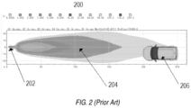
- Fig. 2 the beam spread (200) of a prior art headlight assembly 202 is shown. It can be seen that the headlight beam (204) falls directly on to an oncoming automobile (206). There is a possibility that the light beam will blind the driver of the oncoming vehicle, thus increasing the probability of an accident.
- Fig. 3 the beam spread (300) of a headlight assembly 302 according to an embodiment of the invention is shown.
- the headlight is switched to low-beam mode, and the light from the headlight or the headlight beam (304) does not fall directly on the driver of the oncoming automobile, thus reducing the chances of blinding the driver, and causing an accident.
- the oncoming automobile (304) approaches from the right of the automobile, hence is detected by the detector on the right region of the headlight assembly, and the light source corresponding to the right side of the automobile is switched from high beam to low beam.
Landscapes
- Engineering & Computer Science (AREA)
- Mechanical Engineering (AREA)
- General Engineering & Computer Science (AREA)
- Lighting Device Outwards From Vehicle And Optical Signal (AREA)
Claims (2)
- Scheinwerferanordnung (100) für ein Zweirad mit einem linken Bereich und einem rechten Bereich, wobei die Scheinwerferanordnung (100), so konfiguriert ist, dass sie die Intensität eines Lichtstrahls reduziert, wenn ein entgegenkommendes Fahrzeug erkannt wird, wobei die Scheinwerferanordnung (100) Folgendes umfasst:mindestens zwei Lichtquellen für Fernlicht (102), wobei mindestens eine Fernlichtquelle (102) im linken Bereich und mindestens eine Fernlichtquelle (102) im rechten Bereich angeordnet ist;mindestens zwei Lichtdetektoren (106), die so konfiguriert sind, dass sie das entgegenkommende Fahrzeug erfassen und ein Signal erzeugen, wobei mindestens ein Lichtdetektor (106) in dem linken Bereich und mindestens ein Lichtdetektor (106) in dem rechten Bereich angeordnet ist;ein Steuermodul (108), das so konfiguriert ist, dass es das Signal von mindestens einem Lichtdetektor (106) empfängt und die Intensität des Lichtstrahls durch Ändern der Strahlausbreitung zu reduzieren, wobei das Steuermodul (108) zum Ändern der Strahlausbreitung konfiguriert ist, um selektiv mindestens eine Fernlichtquelle (102) auszuschalten, die dem mindestens einen Lichtdetektor (106) entspricht, von dem das Signal erhalten wird.
- Verfahren zur Verringerung der Intensität eines Lichtbündels einer Scheinwerferanordnung (100) für ein Zweiradfahrzeug, das einen linken Bereich und einen rechten Bereich umfasst,
wobei die Scheinwerferanordnung so konfiguriert ist, dass sie die Intensität des Lichtstrahls reduziert, wenn ein entgegenkommendes Fahrzeug erkannt wird, wobei die Scheinwerferbaugruppe umfasst:mindestens zwei Fernlichtquellen (102), wobei mindestens eine Fernlichtquelle (102) im linken Bereich angeordnet ist und mindestens eine Fernlichtquelle (102) im rechten Bereich positioniert ist;mindestens zwei Lichtdetektoren (106) konfiguriert, um das entgegenkommende Fahrzeug zu erkennen und ein Signal zu erzeugen, wobei mindestens ein Lichtdetektor in dem linken Bereich und mindestens ein Lichtdetektor in dem rechten Bereich angeordnet ist;ein Steuermodul (108) konfiguriert, um das Signal von dem mindestens einen Lichtdetektor (106) zu empfangen und die Intensität des Lichtstrahls zu reduzieren;wobei das Verfahren die folgenden Schritte umfasst:Erfassen des entgegenkommenden Fahrzeugs durch den mindestens einen Detektor (106);Erzeugen eines Signals durch den mindestens einen Lichtdetektor (106);Empfangen des von dem mindestens einen Lichtdetektor (106) erzeugten Signals an dem Steuermodul (108); Aufbereiten des Signals durch das Steuermodul (108), um ein konditioniertes Signal zu erzeugen; undÜbermittlung des konditionierten Signals durch das Steuermodul (108) an die mindestens eine Fernlichtquelle (102); undVerringern der Intensität des Lichtstrahls durch Ändern der Strahlausbreitung, wobei das Ändern der Strahlausbreitung das selektive Abschalten der mindestens einen Fernlichtquelle (102) umfasst, die dem mindestens einen Lichtdetektor (106) entspricht, von dem das Signal empfangen wird.
Applications Claiming Priority (2)
| Application Number | Priority Date | Filing Date | Title |
|---|---|---|---|
| IN201821004044 | 2018-02-02 | ||
| PCT/IN2019/050074 WO2019150391A1 (en) | 2018-02-02 | 2019-02-01 | Automobile headlight assembly |
Publications (4)
| Publication Number | Publication Date |
|---|---|
| EP3746332A1 EP3746332A1 (de) | 2020-12-09 |
| EP3746332A4 EP3746332A4 (de) | 2021-10-27 |
| EP3746332C0 EP3746332C0 (de) | 2023-12-27 |
| EP3746332B1 true EP3746332B1 (de) | 2023-12-27 |
Family
ID=67479074
Family Applications (1)
| Application Number | Title | Priority Date | Filing Date |
|---|---|---|---|
| EP19746856.4A Active EP3746332B1 (de) | 2018-02-02 | 2019-02-01 | Scheinwerferanordnung für zweirad |
Country Status (4)
| Country | Link |
|---|---|
| US (1) | US11247603B2 (de) |
| EP (1) | EP3746332B1 (de) |
| MY (1) | MY206187A (de) |
| WO (1) | WO2019150391A1 (de) |
Families Citing this family (3)
| Publication number | Priority date | Publication date | Assignee | Title |
|---|---|---|---|---|
| WO2020263984A1 (en) * | 2019-06-24 | 2020-12-30 | Event Capture Systems, Inc. | Methods, devices, and systems for headlight illumination for semi-autonomous vehicles |
| KR102916233B1 (ko) | 2021-09-28 | 2026-01-26 | 단국대학교 천안캠퍼스 산학협력단 | 생리활성인자 탑재/세포 부착이 가능한 다공성 구조를 가지는 고분자 필름 및 이의 제조방법 |
| CN117698880A (zh) * | 2023-12-20 | 2024-03-15 | 天津爱玛车业科技有限公司 | 电动两轮车远近光的自动控制系统和方法 |
Family Cites Families (20)
| Publication number | Priority date | Publication date | Assignee | Title |
|---|---|---|---|---|
| US6822563B2 (en) * | 1997-09-22 | 2004-11-23 | Donnelly Corporation | Vehicle imaging system with accessory control |
| US6861809B2 (en) | 1998-09-18 | 2005-03-01 | Gentex Corporation | Headlamp control to prevent glare |
| JP4333887B2 (ja) * | 1999-03-31 | 2009-09-16 | 本田技研工業株式会社 | 車両用前照灯装置 |
| FR2824513B1 (fr) | 2001-05-11 | 2003-07-25 | Valeo Vision | Dispositif d'eclairage en virage pour un vehicule automobile |
| EP1316474A3 (de) | 2001-10-31 | 2006-05-31 | Dana Corporation | Automatische Steurungseinrichtung der Richtung von Fahrzeugsscheinwerfern |
| US20030137849A1 (en) * | 2002-01-22 | 2003-07-24 | Alden Ray M. | Segmented distribution headlight system, method, and apparatus |
| DE102005017933B4 (de) | 2005-04-18 | 2007-02-15 | Torsten Gross | Automatische Abblendvorrichtung |
| US8384289B2 (en) * | 2009-02-20 | 2013-02-26 | Keith Thomas | Method and system for a light sensing headlight modulator |
| FR2963922B1 (fr) | 2010-08-18 | 2014-08-29 | Quality Electronics Design S A | Phare frontal pour vehicule a deux roues |
| CN102009614A (zh) | 2010-12-01 | 2011-04-13 | 孙宝良 | 一种汽车远近光切换系统 |
| JP2013067343A (ja) | 2011-09-26 | 2013-04-18 | Koito Mfg Co Ltd | 車両用配光制御システム |
| US8823346B2 (en) | 2011-12-09 | 2014-09-02 | Intersil Americas LLC | System and method of feed forward for boost converters with improved power factor and reduced energy storage |
| JP2013193562A (ja) | 2012-03-19 | 2013-09-30 | Yamaha Motor Co Ltd | リーン姿勢で旋回する車両用のサブヘッドライトユニット及びサブヘッドライトシステム、並びにリーン姿勢で旋回する車両 |
| JP2013248988A (ja) * | 2012-05-31 | 2013-12-12 | Yamaha Motor Co Ltd | リーン姿勢で旋回する車両用のサブヘッドライトユニット及びサブヘッドライトシステム、並びにリーン姿勢で旋回する車両 |
| JP6026879B2 (ja) * | 2012-12-14 | 2016-11-16 | 川崎重工業株式会社 | 自動二輪車のヘッドランプ装置 |
| DE102013012325A1 (de) | 2013-07-25 | 2015-01-29 | GM Global Technology Operations LLC (n. d. Ges. d. Staates Delaware) | Fahrerassistenzsystem und Betriebsverfahren dafür |
| JP2015033944A (ja) * | 2013-08-09 | 2015-02-19 | スタンレー電気株式会社 | 車両用前照灯の点灯制御装置、車両用前照灯システム |
| US10023103B2 (en) | 2013-09-13 | 2018-07-17 | J.W. Speaker, Corporation | Systems and methods for illumination control and distribution during a vehicle bank |
| JP5837029B2 (ja) * | 2013-12-26 | 2015-12-24 | 本田技研工業株式会社 | 車両の前方視認装置 |
| JP6923310B2 (ja) * | 2016-11-29 | 2021-08-18 | 株式会社小糸製作所 | 車両用ランプの点灯制御装置 |
-
2019
- 2019-02-01 EP EP19746856.4A patent/EP3746332B1/de active Active
- 2019-02-01 MY MYPI2020003923A patent/MY206187A/en unknown
- 2019-02-01 US US16/966,878 patent/US11247603B2/en active Active
- 2019-02-01 WO PCT/IN2019/050074 patent/WO2019150391A1/en not_active Ceased
Also Published As
| Publication number | Publication date |
|---|---|
| EP3746332A4 (de) | 2021-10-27 |
| MY206187A (en) | 2024-12-03 |
| US11247603B2 (en) | 2022-02-15 |
| EP3746332C0 (de) | 2023-12-27 |
| US20210039549A1 (en) | 2021-02-11 |
| WO2019150391A1 (en) | 2019-08-08 |
| EP3746332A1 (de) | 2020-12-09 |
Similar Documents
| Publication | Publication Date | Title |
|---|---|---|
| US7156542B2 (en) | Vehicle headlight system having digital beam-forming optics | |
| US9260053B2 (en) | Automotive headlamp system and method of controlling the same | |
| US10137827B2 (en) | Position lighting device | |
| JP4508202B2 (ja) | 車両間情報伝達システム | |
| US8874312B2 (en) | Automotive headlamp control apparatus and method | |
| US20160318437A1 (en) | Adaptive lighting apparatus | |
| US10293740B2 (en) | Method for the operation of a headlight and motor vehicle headlight | |
| EP1970249A2 (de) | Verfahren und System zur Unterstützung beim Fahren eines Fahrzeugs | |
| US20130169155A1 (en) | Headlamp device and luminance control method therefor | |
| JP6841020B2 (ja) | ポジション照明装置および車両 | |
| US20190202345A1 (en) | Vehicle lighting system | |
| US11247603B2 (en) | Automobile headlight assembly | |
| EP2666671B1 (de) | Fahrzeugscheinwerfersystem und Verfahren zu dessen Steuerung | |
| US12358586B2 (en) | Headlight device and leaning vehicle | |
| US20240349411A1 (en) | Lamp system of mobile body and control method thereof | |
| US11148582B2 (en) | Automobile headlight assembly | |
| JP2007230505A (ja) | 車両用ランプ制御装置 | |
| JP6725396B2 (ja) | 車両用灯具システム | |
| WO2012127294A1 (en) | Bicycle detection system and irradiation control system | |
| KR102823124B1 (ko) | 공사장 운행 시의 차량 조명 조정 방법 및 차량 | |
| US12503040B2 (en) | Vehicle lighting device | |
| US20250178518A1 (en) | Variable lamp system for vehicles that reduces glare | |
| KR20130108784A (ko) | 자동차 전조등 제어 장치 및 방법 | |
| US20080205072A1 (en) | Motor Vehicle Low-Beam Headlight System | |
| KR20160074904A (ko) | 차량용 램프 및 그 제어 방법 |
Legal Events
| Date | Code | Title | Description |
|---|---|---|---|
| STAA | Information on the status of an ep patent application or granted ep patent |
Free format text: STATUS: THE INTERNATIONAL PUBLICATION HAS BEEN MADE |
|
| PUAI | Public reference made under article 153(3) epc to a published international application that has entered the european phase |
Free format text: ORIGINAL CODE: 0009012 |
|
| STAA | Information on the status of an ep patent application or granted ep patent |
Free format text: STATUS: REQUEST FOR EXAMINATION WAS MADE |
|
| 17P | Request for examination filed |
Effective date: 20200730 |
|
| AK | Designated contracting states |
Kind code of ref document: A1 Designated state(s): AL AT BE BG CH CY CZ DE DK EE ES FI FR GB GR HR HU IE IS IT LI LT LU LV MC MK MT NL NO PL PT RO RS SE SI SK SM TR |
|
| AX | Request for extension of the european patent |
Extension state: BA ME |
|
| DAV | Request for validation of the european patent (deleted) | ||
| DAX | Request for extension of the european patent (deleted) | ||
| A4 | Supplementary search report drawn up and despatched |
Effective date: 20210928 |
|
| RIC1 | Information provided on ipc code assigned before grant |
Ipc: B62J 6/024 20200101ALI20210922BHEP Ipc: B62J 6/022 20200101ALI20210922BHEP Ipc: B60Q 1/14 20060101ALI20210922BHEP Ipc: B60Q 1/00 20060101ALI20210922BHEP Ipc: B60Q 1/04 20060101AFI20210922BHEP |
|
| GRAP | Despatch of communication of intention to grant a patent |
Free format text: ORIGINAL CODE: EPIDOSNIGR1 |
|
| STAA | Information on the status of an ep patent application or granted ep patent |
Free format text: STATUS: GRANT OF PATENT IS INTENDED |
|
| INTG | Intention to grant announced |
Effective date: 20230704 |
|
| RIN1 | Information on inventor provided before grant (corrected) |
Inventor name: RAMRAO KHADKE, BALASAHEB Inventor name: VIJAY NERURKAR, ADITI Inventor name: RAMESH AHUJA, LALIT |
|
| GRAS | Grant fee paid |
Free format text: ORIGINAL CODE: EPIDOSNIGR3 |
|
| GRAA | (expected) grant |
Free format text: ORIGINAL CODE: 0009210 |
|
| STAA | Information on the status of an ep patent application or granted ep patent |
Free format text: STATUS: THE PATENT HAS BEEN GRANTED |
|
| AK | Designated contracting states |
Kind code of ref document: B1 Designated state(s): AL AT BE BG CH CY CZ DE DK EE ES FI FR GB GR HR HU IE IS IT LI LT LU LV MC MK MT NL NO PL PT RO RS SE SI SK SM TR |
|
| REG | Reference to a national code |
Ref country code: GB Ref legal event code: FG4D |
|
| REG | Reference to a national code |
Ref country code: CH Ref legal event code: EP |
|
| REG | Reference to a national code |
Ref country code: DE Ref legal event code: R096 Ref document number: 602019044034 Country of ref document: DE |
|
| REG | Reference to a national code |
Ref country code: IE Ref legal event code: FG4D |
|
| U01 | Request for unitary effect filed |
Effective date: 20240126 |
|
| U07 | Unitary effect registered |
Designated state(s): AT BE BG DE DK EE FI FR IT LT LU LV MT NL PT SE SI Effective date: 20240207 |
|
| U20 | Renewal fee for the european patent with unitary effect paid |
Year of fee payment: 6 Effective date: 20240222 |
|
| PG25 | Lapsed in a contracting state [announced via postgrant information from national office to epo] |
Ref country code: GR Free format text: LAPSE BECAUSE OF FAILURE TO SUBMIT A TRANSLATION OF THE DESCRIPTION OR TO PAY THE FEE WITHIN THE PRESCRIBED TIME-LIMIT Effective date: 20240328 |
|
| PG25 | Lapsed in a contracting state [announced via postgrant information from national office to epo] |
Ref country code: ES Free format text: LAPSE BECAUSE OF FAILURE TO SUBMIT A TRANSLATION OF THE DESCRIPTION OR TO PAY THE FEE WITHIN THE PRESCRIBED TIME-LIMIT Effective date: 20231227 |
|
| PG25 | Lapsed in a contracting state [announced via postgrant information from national office to epo] |
Ref country code: GR Free format text: LAPSE BECAUSE OF FAILURE TO SUBMIT A TRANSLATION OF THE DESCRIPTION OR TO PAY THE FEE WITHIN THE PRESCRIBED TIME-LIMIT Effective date: 20240328 Ref country code: ES Free format text: LAPSE BECAUSE OF FAILURE TO SUBMIT A TRANSLATION OF THE DESCRIPTION OR TO PAY THE FEE WITHIN THE PRESCRIBED TIME-LIMIT Effective date: 20231227 |
|
| PG25 | Lapsed in a contracting state [announced via postgrant information from national office to epo] |
Ref country code: RS Free format text: LAPSE BECAUSE OF FAILURE TO SUBMIT A TRANSLATION OF THE DESCRIPTION OR TO PAY THE FEE WITHIN THE PRESCRIBED TIME-LIMIT Effective date: 20231227 Ref country code: NO Free format text: LAPSE BECAUSE OF FAILURE TO SUBMIT A TRANSLATION OF THE DESCRIPTION OR TO PAY THE FEE WITHIN THE PRESCRIBED TIME-LIMIT Effective date: 20240327 Ref country code: HR Free format text: LAPSE BECAUSE OF FAILURE TO SUBMIT A TRANSLATION OF THE DESCRIPTION OR TO PAY THE FEE WITHIN THE PRESCRIBED TIME-LIMIT Effective date: 20231227 |
|
| PG25 | Lapsed in a contracting state [announced via postgrant information from national office to epo] |
Ref country code: IS Free format text: LAPSE BECAUSE OF FAILURE TO SUBMIT A TRANSLATION OF THE DESCRIPTION OR TO PAY THE FEE WITHIN THE PRESCRIBED TIME-LIMIT Effective date: 20240427 |
|
| PG25 | Lapsed in a contracting state [announced via postgrant information from national office to epo] |
Ref country code: CZ Free format text: LAPSE BECAUSE OF FAILURE TO SUBMIT A TRANSLATION OF THE DESCRIPTION OR TO PAY THE FEE WITHIN THE PRESCRIBED TIME-LIMIT Effective date: 20231227 |
|
| PG25 | Lapsed in a contracting state [announced via postgrant information from national office to epo] |
Ref country code: SK Free format text: LAPSE BECAUSE OF FAILURE TO SUBMIT A TRANSLATION OF THE DESCRIPTION OR TO PAY THE FEE WITHIN THE PRESCRIBED TIME-LIMIT Effective date: 20231227 |
|
| PG25 | Lapsed in a contracting state [announced via postgrant information from national office to epo] |
Ref country code: SM Free format text: LAPSE BECAUSE OF FAILURE TO SUBMIT A TRANSLATION OF THE DESCRIPTION OR TO PAY THE FEE WITHIN THE PRESCRIBED TIME-LIMIT Effective date: 20231227 Ref country code: SK Free format text: LAPSE BECAUSE OF FAILURE TO SUBMIT A TRANSLATION OF THE DESCRIPTION OR TO PAY THE FEE WITHIN THE PRESCRIBED TIME-LIMIT Effective date: 20231227 Ref country code: RO Free format text: LAPSE BECAUSE OF FAILURE TO SUBMIT A TRANSLATION OF THE DESCRIPTION OR TO PAY THE FEE WITHIN THE PRESCRIBED TIME-LIMIT Effective date: 20231227 Ref country code: IS Free format text: LAPSE BECAUSE OF FAILURE TO SUBMIT A TRANSLATION OF THE DESCRIPTION OR TO PAY THE FEE WITHIN THE PRESCRIBED TIME-LIMIT Effective date: 20240427 Ref country code: CZ Free format text: LAPSE BECAUSE OF FAILURE TO SUBMIT A TRANSLATION OF THE DESCRIPTION OR TO PAY THE FEE WITHIN THE PRESCRIBED TIME-LIMIT Effective date: 20231227 |
|
| PG25 | Lapsed in a contracting state [announced via postgrant information from national office to epo] |
Ref country code: PL Free format text: LAPSE BECAUSE OF FAILURE TO SUBMIT A TRANSLATION OF THE DESCRIPTION OR TO PAY THE FEE WITHIN THE PRESCRIBED TIME-LIMIT Effective date: 20231227 |
|
| PG25 | Lapsed in a contracting state [announced via postgrant information from national office to epo] |
Ref country code: PL Free format text: LAPSE BECAUSE OF FAILURE TO SUBMIT A TRANSLATION OF THE DESCRIPTION OR TO PAY THE FEE WITHIN THE PRESCRIBED TIME-LIMIT Effective date: 20231227 |
|
| PG25 | Lapsed in a contracting state [announced via postgrant information from national office to epo] |
Ref country code: MC Free format text: LAPSE BECAUSE OF FAILURE TO SUBMIT A TRANSLATION OF THE DESCRIPTION OR TO PAY THE FEE WITHIN THE PRESCRIBED TIME-LIMIT Effective date: 20231227 |
|
| REG | Reference to a national code |
Ref country code: DE Ref legal event code: R097 Ref document number: 602019044034 Country of ref document: DE Ref country code: CH Ref legal event code: PL |
|
| PG25 | Lapsed in a contracting state [announced via postgrant information from national office to epo] |
Ref country code: CH Free format text: LAPSE BECAUSE OF NON-PAYMENT OF DUE FEES Effective date: 20240229 |
|
| PG25 | Lapsed in a contracting state [announced via postgrant information from national office to epo] |
Ref country code: CH Free format text: LAPSE BECAUSE OF NON-PAYMENT OF DUE FEES Effective date: 20240229 |
|
| PLBE | No opposition filed within time limit |
Free format text: ORIGINAL CODE: 0009261 |
|
| STAA | Information on the status of an ep patent application or granted ep patent |
Free format text: STATUS: NO OPPOSITION FILED WITHIN TIME LIMIT |
|
| GBPC | Gb: european patent ceased through non-payment of renewal fee |
Effective date: 20240327 |
|
| 26N | No opposition filed |
Effective date: 20240930 |
|
| PG25 | Lapsed in a contracting state [announced via postgrant information from national office to epo] |
Ref country code: GB Free format text: LAPSE BECAUSE OF NON-PAYMENT OF DUE FEES Effective date: 20240327 |
|
| PG25 | Lapsed in a contracting state [announced via postgrant information from national office to epo] |
Ref country code: IE Free format text: LAPSE BECAUSE OF NON-PAYMENT OF DUE FEES Effective date: 20240201 |
|
| PG25 | Lapsed in a contracting state [announced via postgrant information from national office to epo] |
Ref country code: IE Free format text: LAPSE BECAUSE OF NON-PAYMENT OF DUE FEES Effective date: 20240201 Ref country code: GB Free format text: LAPSE BECAUSE OF NON-PAYMENT OF DUE FEES Effective date: 20240327 |
|
| U20 | Renewal fee for the european patent with unitary effect paid |
Year of fee payment: 7 Effective date: 20250221 |
|
| PG25 | Lapsed in a contracting state [announced via postgrant information from national office to epo] |
Ref country code: CY Free format text: LAPSE BECAUSE OF FAILURE TO SUBMIT A TRANSLATION OF THE DESCRIPTION OR TO PAY THE FEE WITHIN THE PRESCRIBED TIME-LIMIT; INVALID AB INITIO Effective date: 20190201 |
|
| PG25 | Lapsed in a contracting state [announced via postgrant information from national office to epo] |
Ref country code: HU Free format text: LAPSE BECAUSE OF FAILURE TO SUBMIT A TRANSLATION OF THE DESCRIPTION OR TO PAY THE FEE WITHIN THE PRESCRIBED TIME-LIMIT; INVALID AB INITIO Effective date: 20190201 |
|
| PG25 | Lapsed in a contracting state [announced via postgrant information from national office to epo] |
Ref country code: TR Free format text: LAPSE BECAUSE OF FAILURE TO SUBMIT A TRANSLATION OF THE DESCRIPTION OR TO PAY THE FEE WITHIN THE PRESCRIBED TIME-LIMIT Effective date: 20231227 |
|
| U20 | Renewal fee for the european patent with unitary effect paid |
Year of fee payment: 8 Effective date: 20260225 |