EP3746387B1 - Procédé permettant de positionner précisément une broche dans un enrouleur automatique de type à tourelle - Google Patents
Procédé permettant de positionner précisément une broche dans un enrouleur automatique de type à tourelle Download PDFInfo
- Publication number
- EP3746387B1 EP3746387B1 EP19908167.0A EP19908167A EP3746387B1 EP 3746387 B1 EP3746387 B1 EP 3746387B1 EP 19908167 A EP19908167 A EP 19908167A EP 3746387 B1 EP3746387 B1 EP 3746387B1
- Authority
- EP
- European Patent Office
- Prior art keywords
- turret
- spindle
- control system
- bobbin
- winding
- Prior art date
- Legal status (The legal status is an assumption and is not a legal conclusion. Google has not performed a legal analysis and makes no representation as to the accuracy of the status listed.)
- Active
Links
Images


Classifications
-
- B—PERFORMING OPERATIONS; TRANSPORTING
- B65—CONVEYING; PACKING; STORING; HANDLING THIN OR FILAMENTARY MATERIAL
- B65H—HANDLING THIN OR FILAMENTARY MATERIAL, e.g. SHEETS, WEBS, CABLES
- B65H54/00—Winding, coiling, or depositing filamentary material
- B65H54/02—Winding and traversing material on to reels, bobbins, tubes, or like package cores or formers
- B65H54/40—Arrangements for rotating packages
- B65H54/52—Drive contact pressure control, e.g. pressing arrangements
-
- B—PERFORMING OPERATIONS; TRANSPORTING
- B65—CONVEYING; PACKING; STORING; HANDLING THIN OR FILAMENTARY MATERIAL
- B65H—HANDLING THIN OR FILAMENTARY MATERIAL, e.g. SHEETS, WEBS, CABLES
- B65H67/00—Replacing or removing cores, receptacles, or completed packages at paying-out, winding, or depositing stations
- B65H67/04—Arrangements for removing completed take-up packages and or replacing by cores, formers, or empty receptacles at winding or depositing stations; Transferring material between adjacent full and empty take-up elements
- B65H67/044—Continuous winding apparatus for winding on two or more winding heads in succession
- B65H67/048—Continuous winding apparatus for winding on two or more winding heads in succession having winding heads arranged on rotary capstan head
-
- B—PERFORMING OPERATIONS; TRANSPORTING
- B65—CONVEYING; PACKING; STORING; HANDLING THIN OR FILAMENTARY MATERIAL
- B65H—HANDLING THIN OR FILAMENTARY MATERIAL, e.g. SHEETS, WEBS, CABLES
- B65H2701/00—Handled material; Storage means
- B65H2701/30—Handled filamentary material
- B65H2701/31—Textiles threads or artificial strands of filaments
Definitions
- the invention relates to an automatic yarn winding turret type device that can reliably position a spindle for winding after the bobbin changeover.
- the automatic turret type winder is used for winding of continuously arriving tapes, threads, or bands onto a bobbin.
- Each spindle is alternately displaced from the normal winding position to the doffing position by every half rotation of the turret.
- the turret keeps on rotating in the same direction at required time intervals or when running spindle reaches its maximum length of carrying winding tapes.
- Each spindle needs precisely controlled rotation around its own axis, so may be driven independently by an electric motor through a suitable mechanism such as a belt and pulley arrangement or with an independent direct driving electrical motor system.
- the encoders or other suitable devices are mounted on the motor for monitoring the motor revolutions, and the signal is communicated to an electronic controller with the help of a suitable cable.
- the controller further sends the electrical signals to the inverter/drive of the active motor which determines the power to be given for the motor driving the spindle.
- Automatic turret type winders were introduced for providing bobbins of polyolefin flat/fibrillated yarns and to improve efficiency, reduce wastages. Automatic changeover process replaces spindle carrying yarn bobbin with empty spindle.
- the turret is rotated by using a clutch and a pulley in synchronicity. Turret rotation is performed by releasing clutch and transferring the driving force to the pulley for rotation. After the turret rotation, correct positioning of empty bobbin is done by drifting bobbin in reverse direction towards the CAM box pressure roller. Ideally, spindle is positioned such that pressure roller should exert pressure uniformly on spindle present for winding. Reverse movement of turret carrying spindle is controlled according to the pre-set time and speed parameters in the control system. Practically, in conventional systems, turret movement is not uniform, and therefore as spindle position after changeover is not precise and motion smooth as required, due to change in mechanical condition.
- Machines of the type being discussed here are generally not operated under entirely dust-free environment. Therefore, as time progresses, accumulation of foreign particles on the mechanical components of the machinery increases even after taking abundant precaution to clean and maintain the machine. Accumulation of particulate matter provides hindrance to smooth motion of moving elements over a period of time. In other words, the system's resistance to smooth movement of components increases due to general wear and tear and accumulation of particulate matter.
- the turret could get jammed due to accumulation of dust particles or may be extra tightened or loosen during maintenance cycle - any of which could affect the turret rotation by making it fast/slow and/or jerky in nature.
- This jerky behavior is generally known as ⁇ Mechanical glitches'.
- Conventional winders are known to unavoidably suffer from improper spindle positioning in respect to CAM pressure roller on account of said mechanical glitches.
- Improper spindle positioning causes a gap between the spindle bobbin which is ready to be wound and the pressure roller, which in turn produces uneven winding tension and therefore non-uniform package density.
- Another object of the present invention is to provide a system with higher accuracy of reaching correct turret position, which reduces possibility of pushing extra on pressure roller due to lower sensitivity in earlier positioning methods.
- the invention relates to an automatic turret type yarn winding device.
- the automatic bobbin changeover process involves winding of slit film tape/yarn on a bobbin, followed by rotation of the turret to bring an empty bobbin into the winding position.
- Pressure rollers are provided to ensure consistent and accurate winding.
- the accurate relative positioning of the bobbins and pressure rollers is important. Wear and tear and particulate dust may cause malfunctioning of winder systems which may affect accuracy of turret rotations and relative positioning of the bobbins and pressure rollers, especially when the turret rotation during bobbin changeover stage is done in a single rotation.
- the invention provides a system and a method to position spindle more precisely in turret type automatic winder, especially to identify correct stationing position of turret spindle after reverse movement post doffing. It involves, during the bobbin changeover process, the step of rotating the turret in at least two discrete rotational movements carried out at controlled speeds, whereby the empty bobbin assumes its accurate winding position.
- the turret rotation is controlled by sensing the current in the motors controlling the spindles.
- the present invention discloses an improved procedure for precise Turret positioning after the bobbin changeover.
- the terms 'precise', 'precisely' or 'accurate' used in this specification in the context of positioning or the spindle or the turret are meant to convey that a good or close to good position of turret or spindle is achieved whereby the best possible quality bobbin is produced.
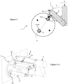
- Figure 1 shows the present invention in an operational state. It shows a turret with spindles, with one spindle in a position to start winding. Each spindle is driven by an associated spindle motor. There is also a motor that drives the turret. Motors are not shown in figure.
- Figure 1 shows the present invention in an operational state. It shows a turret (1) at the start of a winding operation. It has empty first and second bobbins (7, 7A) mounted on two spindles (2A and 2B) with their centres respectively termed as points A and A', which fall on what is termed as a winding-position-line (9) or a bobbin positional axis/line, and where one of the two spindles (2A) is in a winding position to start winding.
- the position of the winding positioning line (9), which is an imaginary axis, is a position that is suitable for winding of yarn and will be known to a person skilled in the art.
- the yarn/tape (3) is delivered after cutting and conditioning from tape line machine from direction 'a' (as indicated in Fig1 ) after passing through a dancing arm which regulates tape tension.
- the tape line speed of discharging tapes varies from 200 to 800 meters per minute; the density of the tape material varies from 400 to 3000 denier.
- Each spindle is driven by an associated spindle motor. There is a motor that drives the turret.
- Tape/yarn (3) winding starts on the presently empty first bobbin (7) after a CAM box (4) bows down by an angle ' ⁇ ' (measured from the vertical) in the direction 'b' (indicated by a counter-clockwise arrow in Figure 1 ).
- the magnitude of the angle is dependent on the turret geometry/design and would be known to a person skilled in the art.
- the first bobbin (7) package diameter grows to a predetermined value.
- a bobbin changeover is expected whereupon the common controller for the winder head instructs the motor of turret driving system (not shown in figures) to rotate for the bobbin changeover, such that the now empty second bobbin (7A) assumes the winding position.
- Figure 2 shows a position of the CAM box (4) where the preset first bobbin (7) diameter after winding of yarn has been achieved.
- the CAM box now rotates in a clockwise direction (i.e. a direction opposite to b) and the pressure roller (5) retracts from the wound first bobbin (7).
- a device that carries out the aforementioned rotation of the CAM box (4) may be an electromechanical, or a pneumatic or hydraulic system.
- the turret (1) begins to rotate in a direction indicated by arrow 'c' in Figure 3 , which shows the turret in a state of transitional movement.
- the turret reaches a position such that the now empty second bobbin (7A) which is mounted on the spindle (2B) reaches a position close to the winding position ( Figure 4 ).
- the centre (A') of the second bobbin (7A) should precisely be at the position previously occupied by the centre (A) of the now-filled first bobbin (7) at the start of its winding.
- the line joining the bobbin centres (A-A') achieved at the end of the transitional movement is not coincidental with the final position for winding represented by the winding positional line (9); actual position of the line joining centres of both bobbins (A-A') at the end of the transitional movement is deliberately drifted by an angle ' ⁇ ' (see Figure 4 ), termed as the displacement angle, with respect to required winding positional line (9).
- the displacement angle ( ⁇ ) may be up to 45°.
- the actual positional line joining the centres (A, A') of two bobbins (7, 7A) at the end of first rotational movement is termed as a close-by positional line (9'). If, as is the conventional manner, after winding of the operational first bobbin (7) is complete, turret (1) at the end of its transitional movement is rotated from its original winding position to its final position (so that the empty second bobbin (7A) is in a winding position) in a single continuous movement (as indicated by rotational direction arrow 'c'), then there is a strong possibility that the spindle needing to be wound would stop before or after the pressure roller location - but not at the precise desired location.
- the final position of the second bobbin (7A) is arrived at as a result of at least two discrete rotational movements.
- the total rotational movement comprises a first and a second rotational movement.
- first rotational movement also termed as first rotational movement (indicated by arrow c in Figure 3 ) for the purpose of this description
- the empty second bobbin (7A) is intentionally stopped at the close-by position (9').
- the pressure roller leans on the empty second bobbin (7A) and exerts a gentle pressure on it before the winding can begin.
- the rotational speed of the first rotational movement depends on various parameters such as the yarn type and denier, line speed, winder designs in general, and would be known to a person skilled in the art.
- the first rotational movement is followed by a second rotational movement (indicated by direction d in Figure 4 ) in the direction required for the second bobbin (7A) to attain the final intended position, which takes place at a speed slower than the first rotational speed.
- a second rotational movement indicated by direction d in Figure 4
- the second rotational movement continues and the second bobbin (7A) approaches its final winding position, and at some point touches the pressure roller (5) which may have already reached its predetermine location or in process of reaching it.
- the current in the spindle motor starts to rise.
- the second rotational movement is stopped when the current in the spindle motor reaches a predetermined value, indicating that the pressure roller (5) and the second bobbin (7A) are in the required final relative positions where the winding can begin.
- the winding of the second bobbin (7A) may have already started before the pressure roller (5) and the second bobbin (7A) assume their required final relative positions.
- the rotational speed (measured in RPM) of the second rotational movement may be up to 25% of the first rotational speed. This is done because controlling the movement at slow speeds to attain accurate final positioning of the second bobbin (7A) is far more feasible or achievable than trying to do so at high speed carried out in a single rotational movement. It is preferable, but not necessary, that the position of the second bobbin (7A) at the end of the first rotational movement is past the intended final position such that the directions c and d may be opposite to each other.
- the position achieved by the second bobbin (7A) at the end of the first rotational movement may optionally be before its final intended position.
- the second rotational movement takes places in the same direction as the first rotational movement, i.e. the directions c and d may be same (i.e. both may be clockwise).
- the final winding position of the second bobbin (7A) is such that the second bobbin (7A) touches the pressure roller (5) at a position where tape tension does not vary much during winding process.
- the second bobbin (7A) reaches required position by rotating slightly in reverse direction 'd' (see Figure 4 ).
- this reverse motion (d) is controlled by set parameters, however, sometimes due to the problems related to the mechanical adjustment of the parts facilitating the motion, the spindle does not reach the correct position. There is therefore a need to provide a procedure that will identify the exact position of the spindle.
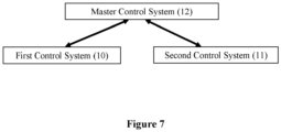
- the present invention also discloses a system to control motions of the turret and the spindles (see Figure 7 ). It comprises a first control system (10) to control the rotational motion of the turret and a second control system (11) to control the rotational motion of the spindle. It also comprises a master control system (12) which controls both systems (10, 11) and receives signal/information from and sends command to the two control systems (10, 11). In other words, at the start of the winding operation, the master control system (12) sends a command to the first control system (10) to start the first rotational motion and stop it upon meeting the criteria outlined in this disclosure. Similarly, the master control also sends a command to the first control system (10) to start the second rotational motion at an appropriate time.
- the master control system (12) receives information from the second control system (11) regarding the upsurge in the spindle current and upon the said spindle current reaching its set threshold value, the master control system (12) instructs the first control system (10) to stop the second rotational motion of the turret and lock it such that the second bobbin (7A) remains in the optimum position.
- a key aspect of the present invention is that the current in the motor that drives the spindle is used to control the stoppage of rotational movement of the turret once the spindle touches the pressure roller.
- a key aspect of the present invention is that the current in the motor that drives the spindle is used to control the stoppage of rotational movement of the turret once the spindle touches the pressure roller.
- the present invention further improves accuracy and responsiveness of the turret movement in regard specified position by sensing the spindle motor current such that when the spindle touches the pressure roller (5), the current of the active spindle motor surges to a definite value more sharply and in a short period up to a threshold value.
- the threshold value can be pre-set below or higher than or equal to motor rated value for releasing command as current reaches set level for specified time duration; when trigger value of spindle motor current reaches to specific value, the master control system (12) sends a command to the first control system (10) to stop at the initial winding position.
- a method to position spindle precisely in turret type automatic winder comprising a rotatable turret (1) driven by a turret motor, said motor being controlled by a turret driving system and said spindle being driven by a spindle motor controlled by a spindle driving system, on which turret (1) at least a first and a second bobbins (7, 7A) are mounted on respective spindles (2A, 2B) in a diametrically opposite position along a winding-positional-line (9), and wherein the first bobbin (7) is positioned in a position of winding a tape/yarn(3) on it whereby, at the start of the tape winding process, said first bobbin (7) touches a pressure roller (5) provided on said winder, said method comprises the step of, upon said first bobbin (7) reaching its predetermined package size, rotating the turret (1) in at least two discrete rotational movements carried out at controlled speeds,
- the first movement is carried out so that said centre (A') of said second bobbin (7A) crosses over said winding-positional-line (9).
- the direction of rotation of said second rotational movement is opposite to the direction of rotation of said first rotational movement.
- the direction of rotation of said second rotational movement is same as the direction of rotation of said first rotational movement.
- the invention also discloses a system to position spindle precisely in turret type automatic winder using the method disclosed in earlier embodiments.
- the system (see Figure 7 ) comprises:
Landscapes
- Replacing, Conveying, And Pick-Finding For Filamentary Materials (AREA)
- Replacement Of Web Rolls (AREA)
- Winding Filamentary Materials (AREA)
Claims (7)
- Procédé permettant de positionner une broche avec précision dans un enrouleur automatique de type à tourelle, ledit enrouleur intégrant une tourelle (1) pouvant être tournée entraînée par un moteur de tourelle, ledit moteur étant commandé par un système d'entraînement de tourelle et ladite broche étant entraînée par un moteur de broche commandé par un système d'entraînement de broche, sur la tourelle (1) duquel au moins une première et une deuxième bobine (7, 7A) sont montées sur des broches (2A, 2B) respectives sur une position diamétralement opposée le long d'une ligne de positionnement d'enroulement (9), et dans lequel la première bobine (7) est positionnée sur une position d'enroulement d'une bande sur celle-ci, où, au début du processus d'enroulement de bande, ladite première bobine (7) touche ainsi un rouleau de pression (5) prévu sur ledit enrouleur, ledit procédé comprend, une fois que ladite première bobine (7) a atteint sa taille d'emballage prédéterminée, l'étape de rotation de la tourelle (1) selon au moins deux mouvements de rotation discrets réalisés à des vitesses commandées, de préférence deux mouvements de rotation discrets, dans lequel un premier mouvement de rotation est réalisé à une première vitesse de rotation commandée jusqu'à un point où les centres (A, A') desdites bobines (7, 7A) se retrouvent sur une ligne de positionnement rapprochée (9'), où ladite ligne de positionnement rapprochée (9') et ladite ligne de positionnement d'enroulement (9) se situent ainsi l'une par rapport à l'autre selon un angle de déplacement fini (Φ), suivi par la rotation de ladite tourelle dans une direction requise à une deuxième vitesse de rotation commandée pour réaliser un deuxième mouvement de rotation jusqu'à un point où ladite deuxième bobine (7A) vide touche ledit rouleau de pression (5), suivi par le déclenchement d'une action d'arrêt et de verrouillage pour arrêter la rotation de ladite tourelle (1), dans lequel ladite deuxième vitesse commandée est inférieure ou égale à la première vitesse commandée, caractérisé en ce que ladite action d'arrêt et de verrouillage comprend les étapes :de surveillance de l'augmentation du courant dans ledit moteur de broche jusqu'à la valeur de seuil prédéterminée, ladite augmentation de courant ayant lieu une fois que la bobine vide touche ledit rouleau de pression (5),d'envoi d'une instruction par un deuxième système de commande (11) fourni pour commander ladite rotation de broche à un système de commande maître (12) fourni pour commander ledit deuxième système de commande (11) l'informant que ledit courant de broche a atteint sa valeur de seuil,d'envoi d'une instruction par ledit système de commande maître (12) à un premier système de commande (10) fourni pour commander la rotation de tourelle, ordonnant ledit premier système de commande (10) d'arrêter le deuxième mouvement de rotation de ladite tourelle (1) puis de verrouiller ladite tourelle (1) sur la position atteinte à la fin dudit deuxième mouvement de rotation.
- Procédé selon la revendication 1, dans lequel ledit premier mouvement est réalisé de telle sorte que ledit centre (A') de ladite deuxième bobine (7A) croise ladite ligne de positionnement d'enroulement (9).
- Procédé selon la revendication 2, dans lequel la direction de rotation dudit deuxième mouvement de rotation est opposée à la direction de rotation dudit premier mouvement de rotation.
- Procédé selon la revendication 2, dans lequel la direction de rotation dudit deuxième mouvement de rotation est la même que la direction de rotation dudit premier mouvement de rotation.
- Procédé selon la revendication 4, dans lequel la valeur de seuil dudit courant de broche est préréglée en dessous ou au-dessus de la valeur nominale dudit moteur de broche.
- Système permettant de positionner une broche avec précision dans un enrouleur automatique type à tourelle en utilisant le procédé selon la revendication 1, caractérisé en ce ledit système comprend :- un premier système de commande (10) pour réaliser lesdits deux mouvements de rotation discrets de ladite tourelle,- un deuxième système de commande (11) pour réaliser ladite rotation desdites broches,- un système de commande maître (12) pour recevoir des informations de et envoyer des consignes à chacun ou aux deux desdits premier et deuxième systèmes de commande (10, 11), dans lequelledit système de commande maître (12) envoie, à réception dudit deuxième système de commande (11) de l'information que l'augmentation du courant de ladite broche a atteint son seuil préréglé, une instruction audit premier système de commande (10) pour arrêter ledit deuxième mouvement de rotation de ladite tourelle (1) et pour verrouiller ladite tourelle dans cette position.
- Système selon la revendication 6, dans lequel la valeur de seuil dudit courant de broche est réglée en dessous ou au-dessus de la valeur nominale dudit moteur de broche.
Applications Claiming Priority (2)
| Application Number | Priority Date | Filing Date | Title |
|---|---|---|---|
| IN201911000599 | 2019-01-07 | ||
| PCT/IB2019/061387 WO2020144530A1 (fr) | 2019-01-07 | 2019-12-27 | Procédé permettant de positionner précisément une broche dans un enrouleur automatique de type à tourelle |
Publications (3)
| Publication Number | Publication Date |
|---|---|
| EP3746387A1 EP3746387A1 (fr) | 2020-12-09 |
| EP3746387A4 EP3746387A4 (fr) | 2021-05-05 |
| EP3746387B1 true EP3746387B1 (fr) | 2023-07-26 |
Family
ID=71520960
Family Applications (1)
| Application Number | Title | Priority Date | Filing Date |
|---|---|---|---|
| EP19908167.0A Active EP3746387B1 (fr) | 2019-01-07 | 2019-12-27 | Procédé permettant de positionner précisément une broche dans un enrouleur automatique de type à tourelle |
Country Status (4)
| Country | Link |
|---|---|
| EP (1) | EP3746387B1 (fr) |
| CN (1) | CN111819142B (fr) |
| TW (1) | TWI768276B (fr) |
| WO (1) | WO2020144530A1 (fr) |
Family Cites Families (17)
| Publication number | Priority date | Publication date | Assignee | Title |
|---|---|---|---|---|
| CN1003994B (zh) * | 1985-03-26 | 1989-04-26 | 巴马股份公司 | 卷取装置 |
| TW252998B (fr) * | 1992-03-05 | 1995-08-01 | Barmag Barmer Maschf | |
| JP2982733B2 (ja) * | 1997-02-26 | 1999-11-29 | 村田機械株式会社 | 紡糸巻取機の巻取制御装置 |
| TW483866B (en) * | 1997-03-25 | 2002-04-21 | Barmag Barmer Maschf | Method of winding an advancing yarn and takeup machine for carrying out such method |
| DE19832809A1 (de) * | 1997-07-26 | 1999-01-28 | Barmag Barmer Maschf | Verfahren zur Steuerung einer Aufspulmaschine |
| KR100319266B1 (ko) * | 1999-01-20 | 2002-01-05 | 전영도 | 탄성사의 권취장치 및 권취방법 |
| DE10253489A1 (de) * | 2001-12-12 | 2003-07-03 | Barmag Barmer Maschf | Verfahren zur Steuerung einer Auflagekraft zwischen einer Andrückwalze und einem Fadenwickel |
| DE10206288A1 (de) * | 2002-02-15 | 2003-08-28 | Schlafhorst & Co W | Verfahren und Vorrichtung zum Betreiben einer Arbeitsstelle einer Kreuzspulen herstellenden Textilmaschine |
| DE10213108A1 (de) * | 2002-03-23 | 2003-10-02 | Neumag Gmbh & Co Kg | Verfahren zur Steuerung einer Aufspulmaschine sowie eine Aufspulmaschine |
| DE10303641A1 (de) * | 2002-04-23 | 2003-11-06 | Neumag Gmbh & Co Kg | Verfahren und Steuerung einer Aufspulmaschine |
| DE102004052564A1 (de) * | 2004-10-29 | 2006-05-04 | Saurer Gmbh & Co. Kg | Verfahren und Vorrichtung zum Betreiben einer Arbeitsstelle einer Kreuzspulen herstellenden Textilmaschine |
| DE102005029937B4 (de) * | 2005-06-28 | 2014-02-20 | Saurer Germany Gmbh & Co. Kg | Verfahren zur Ermittlung der Qualitätsparameter eines Fadens |
| WO2011144732A1 (fr) * | 2010-05-20 | 2011-11-24 | Oerlikon Textile Gmbh & Co. Kg | Machine de bobinage et procédé de surveillance d'une machine de bobinage |
| CN102009874A (zh) * | 2010-11-16 | 2011-04-13 | 北京中丽制机工程技术有限公司 | 卷绕机转盘传动装置的控制方法 |
| CN102183916B (zh) * | 2010-12-09 | 2012-12-26 | 中国兵器工业第二〇五研究所 | 有限转角伺服转台用位置寻零方法 |
| CN104960981B (zh) * | 2015-04-14 | 2017-11-03 | 郑州中远氨纶工程技术有限公司 | 弹性纱线卷绕装置及弹性纱线切换卷绕方法 |
| WO2017093950A1 (fr) * | 2015-12-03 | 2017-06-08 | Siddharth LOHIA | Procédé pour positionner une broche avec précision dans un enrouleur automatique de type tourelle |
-
2019
- 2019-12-27 WO PCT/IB2019/061387 patent/WO2020144530A1/fr not_active Ceased
- 2019-12-27 CN CN201980017244.1A patent/CN111819142B/zh active Active
- 2019-12-27 EP EP19908167.0A patent/EP3746387B1/fr active Active
-
2020
- 2020-01-06 TW TW109100319A patent/TWI768276B/zh not_active IP Right Cessation
Also Published As
| Publication number | Publication date |
|---|---|
| WO2020144530A1 (fr) | 2020-07-16 |
| TWI768276B (zh) | 2022-06-21 |
| CN111819142A (zh) | 2020-10-23 |
| CN111819142B (zh) | 2022-04-29 |
| BR112020020026A2 (pt) | 2021-01-05 |
| EP3746387A1 (fr) | 2020-12-09 |
| TW202031582A (zh) | 2020-09-01 |
| EP3746387A4 (fr) | 2021-05-05 |
Similar Documents
| Publication | Publication Date | Title |
|---|---|---|
| EP3383780B1 (fr) | Procédé pour positionner une broche avec précision dans un enrouleur automatique de type tourelle | |
| US5029762A (en) | Yarn winding apparatus and method | |
| US4805844A (en) | Method and apparatus for monitoring and controlling winding operation of a winding station in a textile winding machine | |
| US6045081A (en) | Method and apparatus for winding a continuously advancing yarn | |
| CN101837909A (zh) | 操作制造交叉卷绕筒子的纺织机的工位的方法和装置以及执行该方法的工位 | |
| US5595351A (en) | Method for controlling a winding station of a bobbin winding machine when a take-up bobbin is changed and winding station for performing the method | |
| US5301886A (en) | Method and apparatus for winding textile yarn from a supply package onto a take-up package including responding to a falsely reported yarn break situation | |
| CN1152901A (zh) | 卷绕机的旋转传动装置的控制方法 | |
| JP2917947B2 (ja) | 弾性糸用紡糸巻取機とその糸切換え方法 | |
| TWI548584B (zh) | 捲線機及其操作方法 | |
| EP3746387B1 (fr) | Procédé permettant de positionner précisément une broche dans un enrouleur automatique de type à tourelle | |
| JPS6364376B2 (fr) | ||
| EP2105400B1 (fr) | Machine de bobbinage de fil et procédé de bobbinage de fil | |
| EP0265995B1 (fr) | Dispositif de régulation des moyens d'entraînement dans le bobinage de fils sur machines textiles | |
| CN104129681A (zh) | 纱线卷绕机 | |
| JP2000026021A (ja) | 綾巻きボビンを作製する繊維機械の作動方法 | |
| US4964581A (en) | Bobbin winding method comprising variable-duration interventions for restoring yarn continuity, and devices for its implementation | |
| JP2539756B2 (ja) | 糸条類のスプ―ル巻き方法及び装置 | |
| RU2037460C1 (ru) | Машина для непрерывной намотки нити | |
| EP1598295B1 (fr) | Dispostif et procédé pour former une réserve de fil dans des machines de textiles comme des métiers à filer, des machines à texturer, des machines de mercerisage ou semblable | |
| US5056727A (en) | Device for preventing yarn loop formation and for saving suctioned yarn on winding units | |
| CN1211532A (zh) | 纱线卷取机的停电处理系统 | |
| EP0316977B1 (fr) | Procédé de bobinage | |
| US4958779A (en) | Method for restoring yarn continuity during bobbin winding, and devices for its implementation | |
| JPH07112869A (ja) | 弾性糸の紡糸巻取方法及び紡糸巻取機 |
Legal Events
| Date | Code | Title | Description |
|---|---|---|---|
| STAA | Information on the status of an ep patent application or granted ep patent |
Free format text: STATUS: THE INTERNATIONAL PUBLICATION HAS BEEN MADE |
|
| PUAI | Public reference made under article 153(3) epc to a published international application that has entered the european phase |
Free format text: ORIGINAL CODE: 0009012 |
|
| STAA | Information on the status of an ep patent application or granted ep patent |
Free format text: STATUS: REQUEST FOR EXAMINATION WAS MADE |
|
| 17P | Request for examination filed |
Effective date: 20200903 |
|
| AK | Designated contracting states |
Kind code of ref document: A1 Designated state(s): AL AT BE BG CH CY CZ DE DK EE ES FI FR GB GR HR HU IE IS IT LI LT LU LV MC MK MT NL NO PL PT RO RS SE SI SK SM TR |
|
| AX | Request for extension of the european patent |
Extension state: BA ME |
|
| A4 | Supplementary search report drawn up and despatched |
Effective date: 20210407 |
|
| RIC1 | Information provided on ipc code assigned before grant |
Ipc: B65H 67/048 20060101AFI20210330BHEP Ipc: B65H 54/52 20060101ALI20210330BHEP |
|
| DAV | Request for validation of the european patent (deleted) | ||
| DAX | Request for extension of the european patent (deleted) | ||
| GRAP | Despatch of communication of intention to grant a patent |
Free format text: ORIGINAL CODE: EPIDOSNIGR1 |
|
| STAA | Information on the status of an ep patent application or granted ep patent |
Free format text: STATUS: GRANT OF PATENT IS INTENDED |
|
| INTG | Intention to grant announced |
Effective date: 20230220 |
|
| GRAS | Grant fee paid |
Free format text: ORIGINAL CODE: EPIDOSNIGR3 |
|
| GRAA | (expected) grant |
Free format text: ORIGINAL CODE: 0009210 |
|
| STAA | Information on the status of an ep patent application or granted ep patent |
Free format text: STATUS: THE PATENT HAS BEEN GRANTED |
|
| AK | Designated contracting states |
Kind code of ref document: B1 Designated state(s): AL AT BE BG CH CY CZ DE DK EE ES FI FR GB GR HR HU IE IS IT LI LT LU LV MC MK MT NL NO PL PT RO RS SE SI SK SM TR |
|
| REG | Reference to a national code |
Ref country code: CH Ref legal event code: EP |
|
| REG | Reference to a national code |
Ref country code: IE Ref legal event code: FG4D |
|
| REG | Reference to a national code |
Ref country code: DE Ref legal event code: R096 Ref document number: 602019033795 Country of ref document: DE |
|
| REG | Reference to a national code |
Ref country code: LT Ref legal event code: MG9D |
|
| REG | Reference to a national code |
Ref country code: NL Ref legal event code: MP Effective date: 20230726 |
|
| PG25 | Lapsed in a contracting state [announced via postgrant information from national office to epo] |
Ref country code: NL Free format text: LAPSE BECAUSE OF FAILURE TO SUBMIT A TRANSLATION OF THE DESCRIPTION OR TO PAY THE FEE WITHIN THE PRESCRIBED TIME-LIMIT Effective date: 20230726 |
|
| PG25 | Lapsed in a contracting state [announced via postgrant information from national office to epo] |
Ref country code: GR Free format text: LAPSE BECAUSE OF FAILURE TO SUBMIT A TRANSLATION OF THE DESCRIPTION OR TO PAY THE FEE WITHIN THE PRESCRIBED TIME-LIMIT Effective date: 20231027 |
|
| PG25 | Lapsed in a contracting state [announced via postgrant information from national office to epo] |
Ref country code: IS Free format text: LAPSE BECAUSE OF FAILURE TO SUBMIT A TRANSLATION OF THE DESCRIPTION OR TO PAY THE FEE WITHIN THE PRESCRIBED TIME-LIMIT Effective date: 20231126 |
|
| PG25 | Lapsed in a contracting state [announced via postgrant information from national office to epo] |
Ref country code: SE Free format text: LAPSE BECAUSE OF FAILURE TO SUBMIT A TRANSLATION OF THE DESCRIPTION OR TO PAY THE FEE WITHIN THE PRESCRIBED TIME-LIMIT Effective date: 20230726 Ref country code: RS Free format text: LAPSE BECAUSE OF FAILURE TO SUBMIT A TRANSLATION OF THE DESCRIPTION OR TO PAY THE FEE WITHIN THE PRESCRIBED TIME-LIMIT Effective date: 20230726 Ref country code: PT Free format text: LAPSE BECAUSE OF FAILURE TO SUBMIT A TRANSLATION OF THE DESCRIPTION OR TO PAY THE FEE WITHIN THE PRESCRIBED TIME-LIMIT Effective date: 20231127 Ref country code: NO Free format text: LAPSE BECAUSE OF FAILURE TO SUBMIT A TRANSLATION OF THE DESCRIPTION OR TO PAY THE FEE WITHIN THE PRESCRIBED TIME-LIMIT Effective date: 20231026 Ref country code: LV Free format text: LAPSE BECAUSE OF FAILURE TO SUBMIT A TRANSLATION OF THE DESCRIPTION OR TO PAY THE FEE WITHIN THE PRESCRIBED TIME-LIMIT Effective date: 20230726 Ref country code: LT Free format text: LAPSE BECAUSE OF FAILURE TO SUBMIT A TRANSLATION OF THE DESCRIPTION OR TO PAY THE FEE WITHIN THE PRESCRIBED TIME-LIMIT Effective date: 20230726 Ref country code: IS Free format text: LAPSE BECAUSE OF FAILURE TO SUBMIT A TRANSLATION OF THE DESCRIPTION OR TO PAY THE FEE WITHIN THE PRESCRIBED TIME-LIMIT Effective date: 20231126 Ref country code: HR Free format text: LAPSE BECAUSE OF FAILURE TO SUBMIT A TRANSLATION OF THE DESCRIPTION OR TO PAY THE FEE WITHIN THE PRESCRIBED TIME-LIMIT Effective date: 20230726 Ref country code: GR Free format text: LAPSE BECAUSE OF FAILURE TO SUBMIT A TRANSLATION OF THE DESCRIPTION OR TO PAY THE FEE WITHIN THE PRESCRIBED TIME-LIMIT Effective date: 20231027 Ref country code: FI Free format text: LAPSE BECAUSE OF FAILURE TO SUBMIT A TRANSLATION OF THE DESCRIPTION OR TO PAY THE FEE WITHIN THE PRESCRIBED TIME-LIMIT Effective date: 20230726 |
|
| PG25 | Lapsed in a contracting state [announced via postgrant information from national office to epo] |
Ref country code: PL Free format text: LAPSE BECAUSE OF FAILURE TO SUBMIT A TRANSLATION OF THE DESCRIPTION OR TO PAY THE FEE WITHIN THE PRESCRIBED TIME-LIMIT Effective date: 20230726 |
|
| PG25 | Lapsed in a contracting state [announced via postgrant information from national office to epo] |
Ref country code: ES Free format text: LAPSE BECAUSE OF FAILURE TO SUBMIT A TRANSLATION OF THE DESCRIPTION OR TO PAY THE FEE WITHIN THE PRESCRIBED TIME-LIMIT Effective date: 20230726 |
|
| REG | Reference to a national code |
Ref country code: DE Ref legal event code: R097 Ref document number: 602019033795 Country of ref document: DE |
|
| PG25 | Lapsed in a contracting state [announced via postgrant information from national office to epo] |
Ref country code: SM Free format text: LAPSE BECAUSE OF FAILURE TO SUBMIT A TRANSLATION OF THE DESCRIPTION OR TO PAY THE FEE WITHIN THE PRESCRIBED TIME-LIMIT Effective date: 20230726 Ref country code: RO Free format text: LAPSE BECAUSE OF FAILURE TO SUBMIT A TRANSLATION OF THE DESCRIPTION OR TO PAY THE FEE WITHIN THE PRESCRIBED TIME-LIMIT Effective date: 20230726 Ref country code: ES Free format text: LAPSE BECAUSE OF FAILURE TO SUBMIT A TRANSLATION OF THE DESCRIPTION OR TO PAY THE FEE WITHIN THE PRESCRIBED TIME-LIMIT Effective date: 20230726 Ref country code: EE Free format text: LAPSE BECAUSE OF FAILURE TO SUBMIT A TRANSLATION OF THE DESCRIPTION OR TO PAY THE FEE WITHIN THE PRESCRIBED TIME-LIMIT Effective date: 20230726 Ref country code: DK Free format text: LAPSE BECAUSE OF FAILURE TO SUBMIT A TRANSLATION OF THE DESCRIPTION OR TO PAY THE FEE WITHIN THE PRESCRIBED TIME-LIMIT Effective date: 20230726 Ref country code: SK Free format text: LAPSE BECAUSE OF FAILURE TO SUBMIT A TRANSLATION OF THE DESCRIPTION OR TO PAY THE FEE WITHIN THE PRESCRIBED TIME-LIMIT Effective date: 20230726 |
|
| PG25 | Lapsed in a contracting state [announced via postgrant information from national office to epo] |
Ref country code: IT Free format text: LAPSE BECAUSE OF FAILURE TO SUBMIT A TRANSLATION OF THE DESCRIPTION OR TO PAY THE FEE WITHIN THE PRESCRIBED TIME-LIMIT Effective date: 20230726 |
|
| PLBE | No opposition filed within time limit |
Free format text: ORIGINAL CODE: 0009261 |
|
| STAA | Information on the status of an ep patent application or granted ep patent |
Free format text: STATUS: NO OPPOSITION FILED WITHIN TIME LIMIT |
|
| 26N | No opposition filed |
Effective date: 20240429 |
|
| PG25 | Lapsed in a contracting state [announced via postgrant information from national office to epo] |
Ref country code: SI Free format text: LAPSE BECAUSE OF FAILURE TO SUBMIT A TRANSLATION OF THE DESCRIPTION OR TO PAY THE FEE WITHIN THE PRESCRIBED TIME-LIMIT Effective date: 20230726 |
|
| REG | Reference to a national code |
Ref country code: CH Ref legal event code: PL |
|
| PG25 | Lapsed in a contracting state [announced via postgrant information from national office to epo] |
Ref country code: LU Free format text: LAPSE BECAUSE OF NON-PAYMENT OF DUE FEES Effective date: 20231227 |
|
| PG25 | Lapsed in a contracting state [announced via postgrant information from national office to epo] |
Ref country code: MC Free format text: LAPSE BECAUSE OF FAILURE TO SUBMIT A TRANSLATION OF THE DESCRIPTION OR TO PAY THE FEE WITHIN THE PRESCRIBED TIME-LIMIT Effective date: 20230726 |
|
| GBPC | Gb: european patent ceased through non-payment of renewal fee |
Effective date: 20231227 |
|
| REG | Reference to a national code |
Ref country code: BE Ref legal event code: MM Effective date: 20231231 |
|
| PG25 | Lapsed in a contracting state [announced via postgrant information from national office to epo] |
Ref country code: MC Free format text: LAPSE BECAUSE OF FAILURE TO SUBMIT A TRANSLATION OF THE DESCRIPTION OR TO PAY THE FEE WITHIN THE PRESCRIBED TIME-LIMIT Effective date: 20230726 Ref country code: LU Free format text: LAPSE BECAUSE OF NON-PAYMENT OF DUE FEES Effective date: 20231227 |
|
| REG | Reference to a national code |
Ref country code: IE Ref legal event code: MM4A |
|
| PG25 | Lapsed in a contracting state [announced via postgrant information from national office to epo] |
Ref country code: IE Free format text: LAPSE BECAUSE OF NON-PAYMENT OF DUE FEES Effective date: 20231227 |
|
| PG25 | Lapsed in a contracting state [announced via postgrant information from national office to epo] |
Ref country code: GB Free format text: LAPSE BECAUSE OF NON-PAYMENT OF DUE FEES Effective date: 20231227 |
|
| PG25 | Lapsed in a contracting state [announced via postgrant information from national office to epo] |
Ref country code: BE Free format text: LAPSE BECAUSE OF NON-PAYMENT OF DUE FEES Effective date: 20231231 |
|
| PG25 | Lapsed in a contracting state [announced via postgrant information from national office to epo] |
Ref country code: FR Free format text: LAPSE BECAUSE OF NON-PAYMENT OF DUE FEES Effective date: 20231231 |
|
| PG25 | Lapsed in a contracting state [announced via postgrant information from national office to epo] |
Ref country code: CH Free format text: LAPSE BECAUSE OF NON-PAYMENT OF DUE FEES Effective date: 20231231 |
|
| PG25 | Lapsed in a contracting state [announced via postgrant information from national office to epo] |
Ref country code: IE Free format text: LAPSE BECAUSE OF NON-PAYMENT OF DUE FEES Effective date: 20231227 Ref country code: GB Free format text: LAPSE BECAUSE OF NON-PAYMENT OF DUE FEES Effective date: 20231227 Ref country code: FR Free format text: LAPSE BECAUSE OF NON-PAYMENT OF DUE FEES Effective date: 20231231 Ref country code: CH Free format text: LAPSE BECAUSE OF NON-PAYMENT OF DUE FEES Effective date: 20231231 Ref country code: BE Free format text: LAPSE BECAUSE OF NON-PAYMENT OF DUE FEES Effective date: 20231231 |
|
| PG25 | Lapsed in a contracting state [announced via postgrant information from national office to epo] |
Ref country code: BG Free format text: LAPSE BECAUSE OF FAILURE TO SUBMIT A TRANSLATION OF THE DESCRIPTION OR TO PAY THE FEE WITHIN THE PRESCRIBED TIME-LIMIT Effective date: 20230726 |
|
| PG25 | Lapsed in a contracting state [announced via postgrant information from national office to epo] |
Ref country code: BG Free format text: LAPSE BECAUSE OF FAILURE TO SUBMIT A TRANSLATION OF THE DESCRIPTION OR TO PAY THE FEE WITHIN THE PRESCRIBED TIME-LIMIT Effective date: 20230726 |
|
| REG | Reference to a national code |
Ref country code: AT Ref legal event code: UEP Ref document number: 1591745 Country of ref document: AT Kind code of ref document: T Effective date: 20230726 |
|
| PG25 | Lapsed in a contracting state [announced via postgrant information from national office to epo] |
Ref country code: CY Free format text: LAPSE BECAUSE OF FAILURE TO SUBMIT A TRANSLATION OF THE DESCRIPTION OR TO PAY THE FEE WITHIN THE PRESCRIBED TIME-LIMIT; INVALID AB INITIO Effective date: 20191227 |
|
| PG25 | Lapsed in a contracting state [announced via postgrant information from national office to epo] |
Ref country code: HU Free format text: LAPSE BECAUSE OF FAILURE TO SUBMIT A TRANSLATION OF THE DESCRIPTION OR TO PAY THE FEE WITHIN THE PRESCRIBED TIME-LIMIT; INVALID AB INITIO Effective date: 20191227 |
|
| PGFP | Annual fee paid to national office [announced via postgrant information from national office to epo] |
Ref country code: AT Payment date: 20251215 Year of fee payment: 7 |
|
| PGFP | Annual fee paid to national office [announced via postgrant information from national office to epo] |
Ref country code: TR Payment date: 20251222 Year of fee payment: 7 |
|
| PGFP | Annual fee paid to national office [announced via postgrant information from national office to epo] |
Ref country code: CZ Payment date: 20251216 Year of fee payment: 7 |
|
| PGFP | Annual fee paid to national office [announced via postgrant information from national office to epo] |
Ref country code: DE Payment date: 20251223 Year of fee payment: 7 |