EP3746722B1 - Système de suivi solaire - Google Patents
Système de suivi solaire Download PDFInfo
- Publication number
- EP3746722B1 EP3746722B1 EP19806976.7A EP19806976A EP3746722B1 EP 3746722 B1 EP3746722 B1 EP 3746722B1 EP 19806976 A EP19806976 A EP 19806976A EP 3746722 B1 EP3746722 B1 EP 3746722B1
- Authority
- EP
- European Patent Office
- Prior art keywords
- frame side
- frame
- bearing
- strut
- supporting pillar
- Prior art date
- Legal status (The legal status is an assumption and is not a legal conclusion. Google has not performed a legal analysis and makes no representation as to the accuracy of the status listed.)
- Active
Links
Images


Classifications
-
- F—MECHANICAL ENGINEERING; LIGHTING; HEATING; WEAPONS; BLASTING
- F24—HEATING; RANGES; VENTILATING
- F24S—SOLAR HEAT COLLECTORS; SOLAR HEAT SYSTEMS
- F24S25/00—Arrangement of stationary mountings or supports for solar heat collector modules
- F24S25/10—Arrangement of stationary mountings or supports for solar heat collector modules extending in directions away from a supporting surface
- F24S25/12—Arrangement of stationary mountings or supports for solar heat collector modules extending in directions away from a supporting surface using posts in combination with upper profiles
-
- F—MECHANICAL ENGINEERING; LIGHTING; HEATING; WEAPONS; BLASTING
- F24—HEATING; RANGES; VENTILATING
- F24S—SOLAR HEAT COLLECTORS; SOLAR HEAT SYSTEMS
- F24S30/00—Arrangements for moving or orienting solar heat collector modules
- F24S30/40—Arrangements for moving or orienting solar heat collector modules for rotary movement
- F24S30/45—Arrangements for moving or orienting solar heat collector modules for rotary movement with two rotation axes
- F24S30/455—Horizontal primary axis
-
- F—MECHANICAL ENGINEERING; LIGHTING; HEATING; WEAPONS; BLASTING
- F24—HEATING; RANGES; VENTILATING
- F24S—SOLAR HEAT COLLECTORS; SOLAR HEAT SYSTEMS
- F24S50/00—Arrangements for controlling solar heat collectors
- F24S50/20—Arrangements for controlling solar heat collectors for tracking
-
- G—PHYSICS
- G05—CONTROLLING; REGULATING
- G05D—SYSTEMS FOR CONTROLLING OR REGULATING NON-ELECTRIC VARIABLES
- G05D3/00—Control of position or direction
- G05D3/10—Control of position or direction without using feedback
- G05D3/105—Solar tracker
-
- H—ELECTRICITY
- H02—GENERATION; CONVERSION OR DISTRIBUTION OF ELECTRIC POWER
- H02S—GENERATION OF ELECTRIC POWER BY CONVERSION OF INFRARED RADIATION, VISIBLE LIGHT OR ULTRAVIOLET LIGHT, e.g. USING PHOTOVOLTAIC [PV] MODULES
- H02S20/00—Supporting structures for PV modules
- H02S20/30—Supporting structures being movable or adjustable, e.g. for angle adjustment
- H02S20/32—Supporting structures being movable or adjustable, e.g. for angle adjustment specially adapted for solar tracking
-
- H—ELECTRICITY
- H02—GENERATION; CONVERSION OR DISTRIBUTION OF ELECTRIC POWER
- H02S—GENERATION OF ELECTRIC POWER BY CONVERSION OF INFRARED RADIATION, VISIBLE LIGHT OR ULTRAVIOLET LIGHT, e.g. USING PHOTOVOLTAIC [PV] MODULES
- H02S30/00—Structural details of PV modules other than those related to light conversion
- H02S30/10—Frame structures
-
- F—MECHANICAL ENGINEERING; LIGHTING; HEATING; WEAPONS; BLASTING
- F24—HEATING; RANGES; VENTILATING
- F24S—SOLAR HEAT COLLECTORS; SOLAR HEAT SYSTEMS
- F24S30/00—Arrangements for moving or orienting solar heat collector modules
- F24S2030/10—Special components
- F24S2030/13—Transmissions
- F24S2030/136—Transmissions for moving several solar collectors by common transmission elements
-
- F—MECHANICAL ENGINEERING; LIGHTING; HEATING; WEAPONS; BLASTING
- F24—HEATING; RANGES; VENTILATING
- F24S—SOLAR HEAT COLLECTORS; SOLAR HEAT SYSTEMS
- F24S30/00—Arrangements for moving or orienting solar heat collector modules
- F24S2030/10—Special components
- F24S2030/15—Bearings
-
- F—MECHANICAL ENGINEERING; LIGHTING; HEATING; WEAPONS; BLASTING
- F24—HEATING; RANGES; VENTILATING
- F24S—SOLAR HEAT COLLECTORS; SOLAR HEAT SYSTEMS
- F24S30/00—Arrangements for moving or orienting solar heat collector modules
- F24S2030/10—Special components
- F24S2030/17—Spherical joints
-
- Y—GENERAL TAGGING OF NEW TECHNOLOGICAL DEVELOPMENTS; GENERAL TAGGING OF CROSS-SECTIONAL TECHNOLOGIES SPANNING OVER SEVERAL SECTIONS OF THE IPC; TECHNICAL SUBJECTS COVERED BY FORMER USPC CROSS-REFERENCE ART COLLECTIONS [XRACs] AND DIGESTS
- Y02—TECHNOLOGIES OR APPLICATIONS FOR MITIGATION OR ADAPTATION AGAINST CLIMATE CHANGE
- Y02E—REDUCTION OF GREENHOUSE GAS [GHG] EMISSIONS, RELATED TO ENERGY GENERATION, TRANSMISSION OR DISTRIBUTION
- Y02E10/00—Energy generation through renewable energy sources
- Y02E10/40—Solar thermal energy, e.g. solar towers
- Y02E10/47—Mountings or tracking
-
- Y—GENERAL TAGGING OF NEW TECHNOLOGICAL DEVELOPMENTS; GENERAL TAGGING OF CROSS-SECTIONAL TECHNOLOGIES SPANNING OVER SEVERAL SECTIONS OF THE IPC; TECHNICAL SUBJECTS COVERED BY FORMER USPC CROSS-REFERENCE ART COLLECTIONS [XRACs] AND DIGESTS
- Y02—TECHNOLOGIES OR APPLICATIONS FOR MITIGATION OR ADAPTATION AGAINST CLIMATE CHANGE
- Y02E—REDUCTION OF GREENHOUSE GAS [GHG] EMISSIONS, RELATED TO ENERGY GENERATION, TRANSMISSION OR DISTRIBUTION
- Y02E10/00—Energy generation through renewable energy sources
- Y02E10/50—Photovoltaic [PV] energy
Definitions
- the present invention relates to a tracking system for the PV module to track sun rays. More particularly present invention relates to system and method for tracking daily and seasonal movement of the sun.
- Dual axis trackers have recently become more popular and improve efficiency by enabling seasonal North-South tracking in addition to the East-West tracking. Broadly their design follows the same principle for East-West tracking ('single-axis polar- mount' or 'parallel-kinematic') while an additional actuator directly attached between the rotating frame and its supporting vertical pillar rotates the frame in the North- South direction.
- the 'dual-axis polar-mount' tracker can only support a limited number of arrays per actuated frame.
- US8459249B2 discloses a solar tracking system with a torque tube supporting solar panels. Columns support the system and have bearings for rotation of the torque tube. A drive is coupled to the torque tube and is driven by a gearbox, such as a worm gear assembly, for rotating the array of solar panels to follow the sun's diurnal motion. The array can rotate in an opposite direction, or backtrack, to prevent shadowing from one module row to another. Multiple gearboxes can be mechanically linked by drive shafts and driven by a single motor. The drive shafts may incorporate universal joints for uneven terrain or staggered configurations. Harmonic dampers can be affixed to the solar panels to decouple wind forces which allow the use of larger solar panels.
- US 20070215199 discloses a two-axis solar tracker is capable of withstanding extreme weather conditions.
- the solar tracker includes a solar array, a frame, a base, a pivot frame, and a first and second actuator.
- the solar array is mounted to the frame and captures sunlight.
- the base is pivotally connected to the frame and defines a pivot axis for elevational movement of the solar array.
- the pivot frame is also pivotally connected to the frame and defines a pivot axis for azimuthal movement of the solar array.
- the first actuator controls elevational movement of the solar array and the second actuator controls azimuthal movement of the solar array.
- the solar tracker is pivotable between a raised position and a stowed position.
- US 8119963 B2 discloses a dual axis solar tracking array frame which is capable of tracking the sun rays on seasonal basis.
- the solar tracking frame includes an array frame to which multiple PV panels are mounted, actuators to rotate the frame and panels, and a control mechanism.
- the array frame is a device consisting of inner frames or panel support structures ("inner frames") and an outer frame all of which rotate around their respective axes to track the sun's daily and seasonal movement. Either the inner frames or the outer frame may track the sun's daily or seasonal movements independently of one another, or both the inner frames and outer frame may track both the sun's daily and seasonal movements cooperatively.
- the inner frames will track in one direction and the outer frame will track the sun's movement in the other direction.
- the inner frames and the outer frame will track the sun's movement in both directions simultaneously so as to optimally position the panels.
- the existing invention restricts the tracking only to daily movement of the sun and not seasonal shifts.
- the existing inventions are too complex with unnecessary complications.
- the existing Inventions are unable to transmit the linear motion of the actuators over large distances.
- the present invention provides solar tracking without having the problems in the prior art. Thus, there is a need for the present invention.
- the main objective of the present invention is to assemble a system for sun rays tracking for PV module.
- the principal objective of the present invention is to develop a system for tracking sun rays on seasonal and daily basis.
- Another objective of the present invention is that present invention should be easily assembled.
- Yet another objective of the present invention is to use less force in order to move large numbers of PV modules and frames.
- Yet another objective of the present invention is to reduce the cost of operation as well as manufacturing cost of the present invention.
- Yet another objective of the present invention is to reduce the repairing time as well as repairing cost.
- Yet another objective of the present invention is that the present invention should be resistance to large wind force.
- Yet another objective of the present invention is that the present invention should be easily transported to any remote location.
- Yet another objective of the present invention is to use minimum number of power drive to move the panels and frames.
- the present invention relates to a two axis solar tracker system according to claim 1.
- the present invention includes a frame, a frame side one bearing, a frame side two bearing, a PV module, an upper beam, a selectively flexible bracket, a first supporting pillar, a second supporting pillar, a lower beam, a first supporting pillar bearing, a second supporting pillar bearing, a first strut, a second strut, a upper beam actuator and a lower beam actuator.
- the frame includes a frame side one, a frame side two, a first cross beam, and a second cross beam.
- the frame side two is parallel to the frame side one.
- the first cross beam is connected between the frame side two and the frame side one perpendicularly.
- the second cross beam is connected between the frame side two and the frame side one, and is parallel to the first cross beam.
- the frame side one bearing is connected to the frame side one.
- the frame side two bearing is connected to the frame side two exactly opposite to the frame side one bearing.
- the PV module is coupled to the frame side one bearing on the frame side one and further coupled to the frame side two bearing on the frame side two.
- the upper beam is below to the frame side one.
- the selectively flexible bracket is connected between the upper beam and the frame side one bearing.
- the lower beam forms a perpendicular sliding pair with the first supporting pillar and the second supporting pillar.
- the first supporting pillar bearing is connected between the first supporting pillar and the first cross beam.
- the second supporting pillar bearing is connected between the second supporting pillar and the second cross beam.
- the first Strut is connected between the first cross beam and the lower beam through a first spherical joint and a second spherical joint.
- the second strut is connected between the second cross beam and the lower beam through a third spherical joint and a fourth spherical joint.
- the upper beam actuator is connected to the upper beam at one end and further connected to the first cross beam at the other end.
- the lower beam actuator is connected to the lower beam at one end and connected to the first supporting pillar at the other end.
- the first spherical joint connects one end of the first strut and the first cross beam and the second spherical joint connects another opposite end of the first strut and the lower beam.
- the third spherical joint connects one end of the second strut and the second cross beam and the fourth spherical joint connects another opposite end of the second strut and the lower beam.
- the translation of the lower beam causes rotation of the frame in north-south direction.
- the PV module is mounted on the frame are rotated in east-west direction by the upper beam.
- the present invention also relates to a method of two axis solar tracker system according to claim 7, the method includes: a method of rotating the PV module and a method of rotating the frame.
- the method of rotating the PV module includes: a force is applied on the upper beam in the direction along the length of the frame side one; the upper beam moves in the direction of applied force; the force from the upper beam transfers to the selectively flexible bracket; the selectively flexible bracket moves to transfer the force applied to a frame side one bearing; the frame side one bearing uses the force applied to rotate; and rotation of the frame side one bearing rotates the PV module; herein the force applied is through the upper beam actuator.
- the method of rotating the frame includes force is applied on the lower beam in the direction parallel to frame side two; the lower beam moves in the direction of the force applied; the force from lower beam transfers to the first strut and the second strut; the position of the first strut and the second strut is adjusted by the force applied with the help of a first spherical joint, a second spherical joint, a third spherical joint and a fourth spherical joint; the force from the first strut and the second strut is transferred to the frame; and the angle of rotation of frame is changed depending on the force applied; herein the force applied is through a lower beam actuator.
- One of the advantages of the present invention is that the present invention tracks sun rays on seasonal and daily basis.
- Yet another advantage of the present invention is that the present invention is easy to assemble.
- Yet another advantage of the present invention is that the present invention reduces the repairing time.
- Yet another advantage of the present invention is that the present invention is easily transported and installed on any remote location.
- Fig. 1 illustrates the top view of the system(100).
- the system(100) includes a frame(102), a frame side one bearing(108), a frame side two bearing(110), a PV module(112), an upper beam(114), a lower beam(120), a first supporting pillar bearing(122), a second supporting pillar bearing(144).
- the frame(102) includes a frame side one(104), a frame side two(106), a first cross beam(124), a second cross beam(142).
- the frame side two(106) is parallel to the frame side one(104).
- the first cross beam(124) is connected between the frame side two(106) and the frame side one(104) perpendicularly.
- the second cross beam(142) is connected between the frame side two(106) and the frame side one(104), and is parallel to the first cross beam(124).
- the frame side one bearing(108) is connected to the frame side one(104).
- the frame side two bearing(110) is connected to the frame side two(106) exactly opposite to the frame side one bearing(108).
- the PV module(112) is coupled to the frame side one bearing(108) on the frame side one(104) and further coupled to the frame side two bearing(110) on the frame side two(106).
- the upper beam(114) is below to the frame side one(104).
- the selectively flexible bracket(116) (shown in fig.2 ) is connected between the upper beam(114) and the frame side one bearing(108).
- the lower beam(120) forms a perpendicular sliding pair with the first supporting pillar(118) and the second supporting pillar (140) (shown in fig.2 ).
- the first supporting pillar bearing(122) is connected between the first supporting pillar(118) (shown in fig.2 ) and the first cross beam(124).
- the second supporting pillar bearing(144) is connected between the second supporting pillar(140) (shown in fig.2 ) and the second cross beam(142).
- Fig. 2 illustrates front view of the system(100).
- the front view of system(100) includes a frame(102), a PV module(112), an upper beam(114), a selectively flexible bracket(116), a first supporting pillar(118), a second supporting pillar(140), a lower beam(120), a first strut(126), a second strut(146) and an upper beam actuator(132).
- the frame(102) includes a first cross beam(124) and a second cross beam(142).
- the PV module(112) is coupled to the frame(102) as shown in fig.1 .
- the upper beam(114) is below to the frame side one (104).
- the selectively flexible bracket(116) is connected between the upper beam(114) and the frame side one bearing(108)(shown in fig.1 ).
- the lower beam(120) forms a perpendicular sliding pair with the first supporting pillar(118) and the second supporting pillar(140).
- the first Strut(126) is connected between the first cross beam(124) and the lower beam(120) through a first spherical joint(128) and a second spherical joint(130).
- the second strut(146) is connected between the second cross beam(142) and the lower beam(120) through a third spherical joint(148) and a fourth spherical joint(150).
- the upper beam actuator(132) is connected to the upper beam(114) at one end and further connected to the first cross beam(124) at the other end.
- the first spherical joint(128) connects one end of the first strut(126) and the first cross beam(124) and the second spherical joint(130) connects another opposite end of the first strut(126) and the lower beam(120).
- the third spherical joint(148) connects one end of the second strut(146) and the second cross beam(142) and the fourth spherical joint(150) connects another opposite end of the second strut (146) and the lower beam(120).
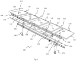
- Fig.3 illustrates isometric view of the system(100).
- the isometric view of system(100) includes a frame(102), a PV module(112), an upper beam(114), a selectively flexible bracket(116), a first supporting pillar(118), a second supporting pillar(140), a lower beam(120), an upper beam actuator(132) and a lower beam actuator(134).
- the frame(102) includes a frame side one(104), a frame side two(106), a first cross beam(124), a second cross beam(142).
- the frame side two(106) is parallel to the frame side one(104).
- the first cross beam(124) is connected between the frame side two(106) and the frame side one(104) perpendicularly.
- the frame side one bearing(108) is connected to the frame side one(104).
- the frame side two bearing(110) is connected to the frame side two(106) exactly opposite to the frame side one bearing(108).
- the PV module(112) is coupled to the frame side one bearing(108) on the frame side one(104) and further coupled to the frame side two bearing(110) on the frame side two(106).
- the upper beam(114) is below to the frame side one(104).
- the selectively flexible bracket(116) is connected between the upper beam(114) and the frame side one bearing(108).
- the lower beam(120) forms a perpendicular sliding pair with the first supporting pillar(118) and the second supporting pillar(140).
- the first supporting pillar bearing(122) (shown in fig.1 ) is connected between the first supporting pillar(118) and the first cross beam(124).
- the second supporting pillar bearing(144) (shown in fig.1 ) is connected between the second supporting pillar(140) and the second cross beam(142).
- the lower beam actuator(134) is connected to the lower beam(120) at one end and connected to the first supporting pillar(118) at the other end.
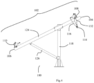
- Fig. 4 illustrate a side view of an embodiment of a system not according to the claims with fixed north-south rotation angle.
- the system(100) includes a frame(102), a frame side one bearing(108), a frame side two bearing(110), an upper beam(114), a selectively flexible bracket(116), a first supporting pillar(118), a first strut(126).
- the frame(102) having a frame side one(104), a frame side two(106) and a first cross beam(124).
- the frame side two(106) is parallel to the frame side one(104).
- the first cross beam(124) is connected between the frame side two(106) and the frame side one(104) perpendicularly.
- the frame side one bearing(108) is connected to the frame side one(104).
- the frame side two bearing(110) is connected to the frame side two(106) exactly opposite to the frame side one bearing(108).
- the upper beam(114) is below to the frame side one (104).
- the upper beam actuator(132) is connected to the upper beam(114) at one end and connected to the first cross beam(124) at the other end.
- the selectively flexible bracket(116) is connected between the upper beam(114) and the at the frame side one bearing(108).
- the first strut(126) is connected between the first cross beam(124) and the first supporting pillar(118) through hinge joint.
- the present invention relates to a two axis solar tracker system.
- the present invention includes a frame, a frame side one bearing, a frame side two bearing, a PV module, an upper beam, a selectively flexible bracket, a first supporting pillar, a second supporting pillar, a lower beam, a first supporting pillar bearing, a second supporting pillar bearing, a first strut, a second strut, an upper beam actuator and a lower beam actuator.
- the frame includes a frame side one, a frame side two, a first cross beam, and a second cross beam.
- the frame side two is parallel to the frame side one.
- the first cross beam is connected between the frame side two and the frame side one perpendicularly.
- the second cross beam is connected between the frame side two and the frame side one, and is parallel to the first cross beam.
- the frame side one bearing is connected to the frame side one.
- the frame side two bearing is connected to the frame side two exactly opposite to the frame side one bearing.
- the PV module is coupled to the frame side one bearing on the frame side one and further coupled to the frame side two bearing on the frame side two.
- the upper beam is below to the frame side one.
- the selectively flexible bracket is connected between the upper beam and the frame side one bearing.
- translation motion of the upper beam is along the length of frame side one.
- the plane of rotation of the frame side one bearing and the frame side two bearing is parallel to translation motion of the upper beam.
- the PV module rotates in east- west direction through the upper beam.
- the lower beam forms a perpendicular sliding pair with the first supporting pillar and the second supporting pillar.
- translation motion of the lower beam is along the length of the frame side two.
- the first supporting pillar bearing is connected between the first supporting pillar and the first cross beam.
- the second supporting pillar bearing is connected between the second supporting pillar and the second cross beam.
- the plane of rotation of the first supporting pillar bearing and the second supporting pillar bearing is perpendicular to translation motion of the lower beam.
- the first Strut is connected between the first cross beam and the lower beam through a first spherical joint and a second spherical joint.
- the second strut is connected between the second cross beam and the lower beam through a third spherical joint and a fourth spherical joint.
- the first spherical joint connects one end of the first strut and the first cross beam and the second spherical joint connects another opposite end of the first strut and the lower beam.
- the third spherical joint connects one end of the second strut and the second cross beam and the fourth spherical joint connects another opposite end of the second strut and the lower beam.
- the upper beam actuator is connected to the upper beam at one end and further connected to the first cross beam at the other end.
- the lower beam actuator is connected to the lower beam at one end and connected to the first supporting pillar at the other end.
- the present invention is a four-bar linkage mechanism, such that the first supporting pillar and the second supporting pillar together act as the fixed link.
- the frame acts as the rotating link and the lower beam acts as the translating link.
- the first strut and the second strut together act as the fourth link connecting the frame and the lower beam.
- the translation of the lower beam causes rotation of the frame in north-south direction.
- the PV module is mounted on the frame are rotated in east-west direction by the upper beam.
- the upper beam actuator and the lower beam actuator includes, but not limited to, a pneumatic drive, a pneumatic motor, a hydraulic drive, a hydraulic motor, and an electric motor.
- the upper beam actuator and the lower beam actuator include the electric motor.
- the frame is able to be rotated in north-south direction with respect to horizontal with large angle range.
- multiple units of the system are able to be arranged in a row and the rotation of the frame is able to be control through the single lower beam actuator.
- multiple units of the PV module are able to rotate in east-west direction through the single upper beam actuator.
- the upper beam actuator and the lower beam actuator are controlled by a programmed microcontroller unit.
- the present invention relates to a two axis solar tracker system.
- the present invention includes a frame, one or more frame side one bearings, one or more frame side two bearings, one or more PV modules, an upper beam, one or more selectively flexible brackets, one or more first supporting pillars, one or more second supporting pillars, a lower beam, one or more first supporting pillar bearings, one or more second supporting pillar bearings, one or more first struts, one or more second struts, a upper beam actuator and a lower beam actuator.
- the frame includes a frame side one, a frame side two, a first cross beam, and a second cross beam.
- the frame side two is parallel to the frame side one.
- the first cross beam is connected between the frame side two and the frame side one perpendicularly.
- the second cross beam is connected between the frame side two and the frame side one, and is parallel to the first cross beam.
- the one or more frame side one bearings are connected to the frame side one.
- the one or more frame side two bearings are connected to the frame side two exactly opposite to the one or more frame side one bearings.
- the one or more PV modules are coupled to the one or more frame side one bearings on the frame side one and further coupled to the one or more frame side two bearings on the frame side two.
- the upper beam is below to the frame side one.
- the one or more selectively flexible brackets are connected between the upper beam and the one or more frame side one bearings.
- translation motion of the upper beam is along the length of frame side one.
- the plane of rotation of the one or more frame side one bearings and the one or more frame side two bearings are parallel to translation motion of the upper beam.
- the lower beam forms a perpendicular sliding pair with the one or more first supporting pillars and the one or more second supporting pillars.
- translation motion of the lower beam is along the length of frame side two.
- the one or more first supporting pillar bearings are connected between the one or more first supporting pillars and the first cross beam.
- the one or more second supporting pillar bearings are connected between the one or more second supporting pillars and the second cross beam.
- the plane of rotation of the one or more first supporting pillar bearings and the one or more second supporting pillar bearings are perpendicular to translation motion of the lower beam.
- the one or more first struts are connected between the first cross beam and the lower beam through one or more first spherical joints and one or more second spherical joints.
- the one or more second struts are connected between the second cross beam and the lower beam through one or more third spherical joints and one or more fourth spherical joints.
- the one or more first spherical joints connect one end of the one or more first struts and the first cross beam.
- the one or more second spherical joints connect another opposite end of the one or more first struts and the lower beam.
- the one or more third spherical joints connect one end of the one or more second struts and the second cross beam.
- the one or more fourth spherical joints connect another opposite end of the one or more second struts and the lower beam.
- the upper beam actuator is connected to the upper beam at one end and further connected to the first cross beam at the other end.
- the lower beam actuator is connected to the lower beam at one end and connected to the one or more first supporting pillars at the other end.
- the present invention is a four-bar linkage mechanism, such that the one or more first supporting pillars and the one or more second supporting pillars together act as the fixed link.
- the frame acts as the rotating link and the lower beam acts as the translating link.
- the one or more first struts and the one or more second struts together act as the fourth link connecting the frame and the lower beam.
- the translation of the lower beam causes rotation of the frame in north-south direction.
- the PV module is mounted on the frame are rotated in east- west direction by the upper beam.
- the upper beam actuator and the lower beam actuator includes, but not limited to, a pneumatic drive, a pneumatic motor, a hydraulic drive, a hydraulic motor, and an electric motor.
- the upper beam actuator and the lower beam actuator include the electric motor.
- the frame is able to be rotated in north-south direction with respect to horizontal with large angle range.
- multiple units of the system are able to be arranged in a row and the rotation of the frame is able to be control through the single lower beam actuator.
- multiple units of the one or more PV modules are able to rotate in east-west direction through the single upper beam actuator.
- the upper beam actuator and the lower beam actuator are controlled by a programmed microcontroller unit.
- the present invention relates to a method of two axis tracking using such a two axis solar tracker system, the method includes:
- the position of the frame is locked in position by a method of locking the frame movement, the method includes:
- the present invention relates to a method of two axis tracking using such a dual axis solar tracker system, the method includes:
- the position of the frame is locked in position by a method of locking the frame movement, the method includes:
- the system includes a frame, a frame side one bearing, a frame side two bearing, a PV module, an upper beam, a selectively flexible bracket, a first supporting pillar, a second supporting pillar, a first strut, a second strut, an upper beam actuator.
- the frame includes a frame side one, a frame side two, a first cross beam, and a second cross beam.
- the frame side two is parallel to the frame side one.
- the first cross beam is connected between the frame side two and the frame side one perpendicularly.
- the second cross beam is connected between the frame side two and the frame side one, and is parallel to the first beam.
- the frame side one bearing is connected to the frame side one.
- the frame side two bearing is connected to the frame side two exactly opposite to the frame side one bearing.
- the PV module is coupled to the frame side one bearing on the frame side one and further coupled to the frame side two bearing on the frame side two.
- the upper beam is below to the frame side one.
- the selectively flexible bracket is connected between the upper beam and the frame side one bearing.
- translation motion of the upper beam is along the length of frame side one.
- the plane of rotation of the frame side one bearing and the frame side two bearing is parallel to translation motion of the upper beam.
- the PV module rotates in east- west direction through the upper beam.
- the top of the first supporting pillar is connected to the first cross beam through hinge joint.
- the top of the second supporting pillar is connected to the second cross beam through hinge joint.
- the first strut is connected between the first cross beam and the first supporting pillar through hinge joint.
- the second strut is connected between the second cross beam and the second supporting pillar through hinge joint.
- one end of the first strut is connected to the first cross beam through hinge joint and another opposite end of the first strut is connected to the first supporting pillar through hinge joint.
- one end of the second strut is connected to the second cross beam through hinge joint and another opposite end of the second strut is connected to the second supporting pillar through hinge joint.
- the upper beam actuator is connected to the upper beam at one end and connected to the first cross beam at the other end.
- translation motion of the upper beam is along the length of frame side one.
- the selectively flexible bracket is designed to transmit rotation.
- position of the frame is fixed by restricting the rotation of the frame in North-South direction.
Landscapes
- Engineering & Computer Science (AREA)
- Life Sciences & Earth Sciences (AREA)
- Sustainable Development (AREA)
- Physics & Mathematics (AREA)
- Chemical & Material Sciences (AREA)
- Thermal Sciences (AREA)
- Sustainable Energy (AREA)
- Combustion & Propulsion (AREA)
- Mechanical Engineering (AREA)
- General Engineering & Computer Science (AREA)
- General Physics & Mathematics (AREA)
- Automation & Control Theory (AREA)
- Photovoltaic Devices (AREA)
Claims (8)
- Système (100) de suivi solaire à deux axes, le système (100) comprenant : un cadre (102), le cadre (102) comportant un côté cadre un (104), un côté cadre deux (106), le côté cadre deux (106) étant parallèle au côté cadre un (104), une première traverse (124), la première traverse (124) étant reliée entre le côté cadre deux (106) et le côté cadre un (104) perpendiculairement, et une seconde traverse (142), la seconde traverse (142) étant reliée entre le côté cadre deux (106) et le côté cadre un (104), et étant parallèle à la première traverse (124), et un au moins un palier côté cadre un (108), l'au moins un palier côté cadre un (108) étant relié au côté cadre un (104) ; un au moins un palier côté cadre deux (110), l'au moins un palier côté cadre deux (110) étant relié au côté cadre deux (106) exactement à l'opposé de l'au moins un palier côté cadre un (108) ; un au moins un panneau solaire (112), l'au moins un panneau solaire (112) étant couplé à l'au moins un palier côté cadre un (108) sur le côté cadre un (104) et en outre couplé à l'au moins un palier côté cadre deux (110) sur le côté cadre deux (106) ; un longeron supérieur (114), le longeron supérieur (114) étant en dessous du côté cadre un (102) ; un au moins un support sélectivement flexible (116), l'au moins un support sélectivement flexible (116) étant relié entre le longeron supérieur (114) et l'au moins un palier côté cadre un (108) ; un au moins un premier montant de support (118) ; un au moins un second montant de support (140) ; un longeron inférieur (120), le longeron inférieur (120) formant une paire coulissante perpendiculaire avec l'au moins un premier montant de support (118) et l'au moins un second montant de support (140) ; un au moins un premier palier de montant de support (112), l'au moins un premier palier de montant de support (112) étant relié entre l'au moins un premier montant de support (118) et la première traverse (124) ; un au moins un second palier de montant de support (144), l'au moins un second palier de montant de support (144) étant relié entre l'au moins un second montant de support (140) et la seconde traverse (142) ; une au moins une première entretoise (126), l'au moins une première entretoise (126) étant reliée entre la première traverse (124) et le longeron inférieur (120) à travers une au moins une première articulation sphérique (128) et une au moins une deuxième articulation sphérique (130) ; une au moins une seconde entretoise (146), l'au moins une seconde entretoise (146) étant reliée entre la seconde traverse (142) et le longeron inférieur (120) à travers une au moins une troisième articulation sphérique (148) et une au moins une quatrième articulation sphérique (150) ; un actionneur de longeron supérieur (132), l'actionneur de longeron supérieur (132) étant relié au longeron supérieur (114) à une extrémité et en outre relié à la première traverse (124) à l'autre extrémité ; et un actionneur de longeron inférieur (134), l'actionneur de longeron inférieur (134) étant relié au longeron inférieur (120) à une extrémité et relié à l'au moins un premier montant de support (118) à l'autre extrémité ; dans lequel le mouvement de translation du longeron supérieur (114) se situe le long de la longueur du côté de cadre un (104), dans lequel le plan de rotation de l'au moins un palier côté cadre un (108) et de l'au moins un palier côté cadre deux (110) est parallèle au mouvement de translation du longeron supérieur (114), dans lequel le mouvement de translation du longeron inférieur (120) se situe le long de la longueur du côté cadre deux (106), dans lequel le plan de rotation du premier palier de montant de support (112) et du second palier de montant de support (144) est perpendiculaire au mouvement de translation de du longeron inférieur (120), dans lequel l'au moins une première articulation sphérique (128) relie une extrémité de l'au moins une première entretoise (126) et la première traverse (124) et l'au moins une deuxième articulation sphérique (130) relie une autre extrémité opposée de l'au moins une première entretoise (126) et le longeron inférieur (120), dans lequel l'au moins une troisième articulation sphérique (148) relie une extrémité de l'au moins une seconde entretoise (146) et la seconde traverse (142) et l'au moins une quatrième articulation sphérique (150) relie une autre extrémité opposée de l'au moins une seconde entretoise (126) et le longeron inférieur (120), dans lequel le système (100) est un mécanisme de liaison à quatre barres, de sorte que l'au moins un premier montant de support (118) et l'au moins un second montant de support (140) agissent conjointement comme liaison fixe, le cadre (102) agit comme liaison rotative et le longeron inférieur (120) agit comme liaison de translation et l'au moins une première entretoise (126) et l'au moins une seconde entretoise (126) agissent conjointement comme quatrième liaison reliant le cadre (102) et le longeron inférieur (120) et donc dans la configuration conçue, la translation du longeron inférieur (120) provoque la rotation du cadre (102).
- Système (100) selon la revendication 1, dans lequel l'actionneur de longeron supérieur (132) et l'actionneur de longeron inférieur (134) sont choisis parmi un entraînement pneumatique, un moteur pneumatique, un entraînement hydraulique, un moteur hydraulique et un moteur électrique.
- Système (100) selon la revendication 1, dans lequel le cadre (102) peut tourner dans la direction nord-sud par rapport à l'horizontale avec une grande plage d'angle.
- Système (100) selon la revendication 1, dans lequel plusieurs unités du système (100) peuvent être agencées en rangée et la rotation du cadre (102) peut être commandée à travers l'actionneur de longeron inférieur (134) seul.
- Système (100) selon la revendication 1, dans lequel plusieurs unités de l'au moins un panneau solaire (112) peuvent tourner dans la direction est-ouest à travers l'actionneur de longeron supérieur (132) seul.
- Système (100) selon la revendication 1, dans lequel l'actionneur de longeron supérieur (132) et l'actionneur de longeron inférieur (134) sont commandés par un système de commande électronique.
- Procédé de suivi solaire à deux axes utilisant un système (100) de suivi solaire à deux axes selon la revendication 1, le procédé comprenant :un procédé de rotation de l'au moins un panneau solaire (112), le procédé comprenant l'application d'une force sur le longeron supérieur (114) dans la direction le long de la longueur du côté cadre un (104) ; le déplacement du longeron supérieur (114) dans la direction de la force appliquée ; le transfert de la force du longeron supérieur (114) à l'au moins un support sélectivement flexible (116) ; le déplacement de l'au moins un support sélectivement flexible (116) pour transférer la force appliquée à l'au moins un palier côté cadre un (108) ; l'utilisation par l'au moins un palier côté cadre un (108) de la force appliquée pour tourner ; et la rotation de l'au moins un palier côté cadre un (108) qui fait tourner l'au moins un panneau solaire (112) ; dans lequel une force est appliquée sur le longeron supérieur (114) à travers l'actionneur de longeron supérieur (132) ;un procédé de rotation du cadre (102), le procédé comprenant l'application d'une force sur le longeron inférieur (120) dans la direction parallèle au côté cadre deux (106) ; le déplacement du longeron inférieur (120) dans la direction de la force appliquée ; le transfert de la force du longeron inférieur (120) à l'au moins une première entretoise (126) et à l'au moins une seconde entretoise (146) ; le réglage de la position de l'au moins une première entretoise (126) et de l'au moins une seconde entretoise (146) par la force appliquée à l'aide de l'au moins une première articulation sphérique (128), de l'au moins une deuxième articulation sphérique (130), de l'au moins une troisième articulation sphérique (148) et de l'au moins une quatrième articulation sphérique (150) ; le transfert de la force de l'au moins une première entretoise (126) et de l'au moins une seconde entretoise (146) au cadre (102) ; et la modification de l'angle de rotation du cadre (102) en fonction de la force appliquée ; dans lequel une force est appliquée sur le longeron inférieur (120) à travers l'actionneur de longeron inférieur (134).
- Procédé selon la revendication 7, dans lequel la position du cadre (102) est verrouillée en position par un procédé de verrouillage de mouvement de cadre (102), le procédé comprenant : le maintien du cadre (102) dans une position perpendiculaire à l'au moins un premier montant de support (118) et à l'au moins un second montant de support (140) ; l'équilibrage des forces indésirables sur le cadre (102) par l'au moins une première entretoise (126) et l'au moins une seconde entretoise (146) verrouillant ainsi la position du cadre (102) ; dans le cas où le cadre (102) n'est pas perpendiculaire à l'au moins un premier montant de support (118) et à l'au moins un second montant de support (140), le déplacement du cadre (102) en position perpendiculaire à l'au moins un premier montant de support (118) et à l'au moins un second montant de support (140) à travers une force appliquée pour être verrouillé en position ; et en cas de déplacement du cadre (102), un procédé de rotation du cadre (102) est exécuté ;
dans lequel la force appliquée pour le verrouillage en position passe par l'actionneur de longeron inférieur (134).
Applications Claiming Priority (2)
| Application Number | Priority Date | Filing Date | Title |
|---|---|---|---|
| IN201811019035 | 2018-05-21 | ||
| PCT/IN2019/050273 WO2019224834A1 (fr) | 2018-05-21 | 2019-04-03 | Système de suivi solaire |
Publications (4)
| Publication Number | Publication Date |
|---|---|
| EP3746722A1 EP3746722A1 (fr) | 2020-12-09 |
| EP3746722A4 EP3746722A4 (fr) | 2021-11-03 |
| EP3746722C0 EP3746722C0 (fr) | 2025-06-04 |
| EP3746722B1 true EP3746722B1 (fr) | 2025-06-04 |
Family
ID=68616619
Family Applications (1)
| Application Number | Title | Priority Date | Filing Date |
|---|---|---|---|
| EP19806976.7A Active EP3746722B1 (fr) | 2018-05-21 | 2019-04-03 | Système de suivi solaire |
Country Status (4)
| Country | Link |
|---|---|
| US (1) | US11114975B2 (fr) |
| EP (1) | EP3746722B1 (fr) |
| CA (1) | CA3100975C (fr) |
| WO (1) | WO2019224834A1 (fr) |
Families Citing this family (4)
| Publication number | Priority date | Publication date | Assignee | Title |
|---|---|---|---|---|
| WO2022056022A1 (fr) | 2020-09-08 | 2022-03-17 | Nextracker Inc. | Suiveur à verrouillage réparti |
| US11728760B2 (en) * | 2021-06-16 | 2023-08-15 | Tectonicus Constructs, Llc | Pivotable support structure for cross canal solar array |
| CN117751263A (zh) * | 2021-07-15 | 2024-03-22 | 拉德哈克里什南.萨.卡 | 水平双轴太阳能跟踪系统 |
| ES1293486Y (es) * | 2022-06-21 | 2022-10-24 | Trina Solar S L U | Rodamiento para sujecion de ejes de giro sobre pilares de sustentacion |
Family Cites Families (7)
| Publication number | Priority date | Publication date | Assignee | Title |
|---|---|---|---|---|
| ES1061617Y (es) * | 2005-12-07 | 2006-06-16 | Garcia Cesareo Rivas | Seguidor solar lineal para instalacion fotovoltaica |
| DE102006010162A1 (de) * | 2006-02-28 | 2007-09-06 | Conergy Ag | Nachführbares Gestell für Solarmodule |
| US7884279B2 (en) | 2006-03-16 | 2011-02-08 | United Technologies Corporation | Solar tracker |
| US8459249B2 (en) | 2007-06-15 | 2013-06-11 | Ronald P. Corio | Single axis solar tracking system |
| MX2012011290A (es) * | 2010-03-29 | 2012-12-17 | Sedona Energy Labs | Sistema de marco para el seguimiento del arreglo solar de eje doble de contrapeso de alto rendimiento. |
| CN204290838U (zh) * | 2014-07-22 | 2015-04-22 | 深圳市安泰科建筑技术有限公司 | 一种可调连杆式太阳能跟踪支架 |
| MX2019000053A (es) * | 2016-07-08 | 2019-05-02 | Alion Energy Inc | Sistemas y métodos para montaje y bloqueo de paneles solares de forma giratoria. |
-
2019
- 2019-04-03 EP EP19806976.7A patent/EP3746722B1/fr active Active
- 2019-04-03 CA CA3100975A patent/CA3100975C/fr active Active
- 2019-04-03 US US16/968,694 patent/US11114975B2/en active Active
- 2019-04-03 WO PCT/IN2019/050273 patent/WO2019224834A1/fr not_active Ceased
Also Published As
| Publication number | Publication date |
|---|---|
| WO2019224834A1 (fr) | 2019-11-28 |
| CA3100975C (fr) | 2023-08-01 |
| US11114975B2 (en) | 2021-09-07 |
| CA3100975A1 (fr) | 2019-11-28 |
| EP3746722A4 (fr) | 2021-11-03 |
| EP3746722C0 (fr) | 2025-06-04 |
| EP3746722A1 (fr) | 2020-12-09 |
| US20210067086A1 (en) | 2021-03-04 |
Similar Documents
| Publication | Publication Date | Title |
|---|---|---|
| JP4527803B1 (ja) | 平面的拡張が容易な軽量薄型の太陽光集光器 | |
| CA2794602C (fr) | Cadre de groupement de suivi solaire a axe double contrebalance a haut rendement | |
| US11114975B2 (en) | Solar tracking system | |
| CN101803043B (zh) | 太阳能发电设备 | |
| EP2060928A1 (fr) | Dispositif de suivi lumineux | |
| MX2013009512A (es) | Sistema se seguimiento solar. | |
| KR100922238B1 (ko) | 태양광 발전장치 | |
| EP3387269B1 (fr) | Suiveur solaire avec dispositif réducteur de jeu | |
| US20120125404A1 (en) | Modular system for concentration of solar radiation | |
| WO2009155530A1 (fr) | Système de concentrateur solaire | |
| US8242424B2 (en) | Single axis solar tracker | |
| US20090159075A1 (en) | Southerly tilted solar tracking system and method | |
| CN102081407A (zh) | 太阳能塔式发电镜场定日镜分组控制装置 | |
| CN110737286B (zh) | 一种光伏组件南北方向倾角可调的平单轴跟踪支架 | |
| CN102062282A (zh) | 光伏组件支架 | |
| CN1982752A (zh) | 驱动采光器全方位运动的机械传动装置及其太阳能系统 | |
| WO2023132806A1 (fr) | Système de suivi solaire | |
| US20230085139A1 (en) | Structure of differential telescopic elliptical arcs, consisting of multiple two-axis sun-trackers mechanisms | |
| US12597883B1 (en) | Photovoltaic tracking system on roofs | |
| CN120263079B (zh) | 一种多角度追光大面积光伏发电系统 | |
| CN110647174A (zh) | 一种基于摩擦传动的立卧一体式双轴减速传动系统 | |
| Roos et al. | A 25m2 target-aligned heliostat with closed-loop control | |
| CN210639467U (zh) | 一种光伏组件南北方向倾角可调的平单轴跟踪支架 | |
| US20190190441A1 (en) | Dual Axis Solar Tracking System | |
| IL303303A (en) | A single-axis modular solar tracking device and a system using this device |
Legal Events
| Date | Code | Title | Description |
|---|---|---|---|
| STAA | Information on the status of an ep patent application or granted ep patent |
Free format text: STATUS: THE INTERNATIONAL PUBLICATION HAS BEEN MADE |
|
| PUAI | Public reference made under article 153(3) epc to a published international application that has entered the european phase |
Free format text: ORIGINAL CODE: 0009012 |
|
| STAA | Information on the status of an ep patent application or granted ep patent |
Free format text: STATUS: REQUEST FOR EXAMINATION WAS MADE |
|
| 17P | Request for examination filed |
Effective date: 20200903 |
|
| AK | Designated contracting states |
Kind code of ref document: A1 Designated state(s): AL AT BE BG CH CY CZ DE DK EE ES FI FR GB GR HR HU IE IS IT LI LT LU LV MC MK MT NL NO PL PT RO RS SE SI SK SM TR |
|
| AX | Request for extension of the european patent |
Extension state: BA ME |
|
| DAV | Request for validation of the european patent (deleted) | ||
| DAX | Request for extension of the european patent (deleted) | ||
| A4 | Supplementary search report drawn up and despatched |
Effective date: 20211006 |
|
| RIC1 | Information provided on ipc code assigned before grant |
Ipc: H02S 20/32 20140101ALI20210930BHEP Ipc: F24S 50/20 20180101AFI20210930BHEP |
|
| GRAP | Despatch of communication of intention to grant a patent |
Free format text: ORIGINAL CODE: EPIDOSNIGR1 |
|
| STAA | Information on the status of an ep patent application or granted ep patent |
Free format text: STATUS: GRANT OF PATENT IS INTENDED |
|
| INTG | Intention to grant announced |
Effective date: 20241218 |
|
| GRAS | Grant fee paid |
Free format text: ORIGINAL CODE: EPIDOSNIGR3 |
|
| GRAA | (expected) grant |
Free format text: ORIGINAL CODE: 0009210 |
|
| STAA | Information on the status of an ep patent application or granted ep patent |
Free format text: STATUS: THE PATENT HAS BEEN GRANTED |
|
| AK | Designated contracting states |
Kind code of ref document: B1 Designated state(s): AL AT BE BG CH CY CZ DE DK EE ES FI FR GB GR HR HU IE IS IT LI LT LU LV MC MK MT NL NO PL PT RO RS SE SI SK SM TR |
|
| REG | Reference to a national code |
Ref country code: GB Ref legal event code: FG4D |
|
| REG | Reference to a national code |
Ref country code: CH Ref legal event code: EP |
|
| REG | Reference to a national code |
Ref country code: DE Ref legal event code: R096 Ref document number: 602019070813 Country of ref document: DE |
|
| REG | Reference to a national code |
Ref country code: IE Ref legal event code: FG4D |
|
| U01 | Request for unitary effect filed |
Effective date: 20250704 |
|
| U07 | Unitary effect registered |
Designated state(s): AT BE BG DE DK EE FI FR IT LT LU LV MT NL PT RO SE SI Effective date: 20250715 |
|
| PG25 | Lapsed in a contracting state [announced via postgrant information from national office to epo] |
Ref country code: ES Free format text: LAPSE BECAUSE OF FAILURE TO SUBMIT A TRANSLATION OF THE DESCRIPTION OR TO PAY THE FEE WITHIN THE PRESCRIBED TIME-LIMIT Effective date: 20250604 |
|
| PG25 | Lapsed in a contracting state [announced via postgrant information from national office to epo] |
Ref country code: NO Free format text: LAPSE BECAUSE OF FAILURE TO SUBMIT A TRANSLATION OF THE DESCRIPTION OR TO PAY THE FEE WITHIN THE PRESCRIBED TIME-LIMIT Effective date: 20250904 Ref country code: GR Free format text: LAPSE BECAUSE OF FAILURE TO SUBMIT A TRANSLATION OF THE DESCRIPTION OR TO PAY THE FEE WITHIN THE PRESCRIBED TIME-LIMIT Effective date: 20250905 |
|
| PG25 | Lapsed in a contracting state [announced via postgrant information from national office to epo] |
Ref country code: PL Free format text: LAPSE BECAUSE OF FAILURE TO SUBMIT A TRANSLATION OF THE DESCRIPTION OR TO PAY THE FEE WITHIN THE PRESCRIBED TIME-LIMIT Effective date: 20250604 |
|
| PG25 | Lapsed in a contracting state [announced via postgrant information from national office to epo] |
Ref country code: HR Free format text: LAPSE BECAUSE OF FAILURE TO SUBMIT A TRANSLATION OF THE DESCRIPTION OR TO PAY THE FEE WITHIN THE PRESCRIBED TIME-LIMIT Effective date: 20250604 |
|
| PG25 | Lapsed in a contracting state [announced via postgrant information from national office to epo] |
Ref country code: RS Free format text: LAPSE BECAUSE OF FAILURE TO SUBMIT A TRANSLATION OF THE DESCRIPTION OR TO PAY THE FEE WITHIN THE PRESCRIBED TIME-LIMIT Effective date: 20250904 |
|
| PG25 | Lapsed in a contracting state [announced via postgrant information from national office to epo] |
Ref country code: IS Free format text: LAPSE BECAUSE OF FAILURE TO SUBMIT A TRANSLATION OF THE DESCRIPTION OR TO PAY THE FEE WITHIN THE PRESCRIBED TIME-LIMIT Effective date: 20251004 |
|
| PG25 | Lapsed in a contracting state [announced via postgrant information from national office to epo] |
Ref country code: SM Free format text: LAPSE BECAUSE OF FAILURE TO SUBMIT A TRANSLATION OF THE DESCRIPTION OR TO PAY THE FEE WITHIN THE PRESCRIBED TIME-LIMIT Effective date: 20250604 |
|
| PG25 | Lapsed in a contracting state [announced via postgrant information from national office to epo] |
Ref country code: CZ Free format text: LAPSE BECAUSE OF FAILURE TO SUBMIT A TRANSLATION OF THE DESCRIPTION OR TO PAY THE FEE WITHIN THE PRESCRIBED TIME-LIMIT Effective date: 20250604 |
|
| PG25 | Lapsed in a contracting state [announced via postgrant information from national office to epo] |
Ref country code: SK Free format text: LAPSE BECAUSE OF FAILURE TO SUBMIT A TRANSLATION OF THE DESCRIPTION OR TO PAY THE FEE WITHIN THE PRESCRIBED TIME-LIMIT Effective date: 20250604 |
|
| PGFP | Annual fee paid to national office [announced via postgrant information from national office to epo] |
Ref country code: GB Payment date: 20260327 Year of fee payment: 8 |
|
| PLBE | No opposition filed within time limit |
Free format text: ORIGINAL CODE: 0009261 |
|
| STAA | Information on the status of an ep patent application or granted ep patent |
Free format text: STATUS: NO OPPOSITION FILED WITHIN TIME LIMIT |
|
| REG | Reference to a national code |
Ref country code: CH Ref legal event code: L10 Free format text: ST27 STATUS EVENT CODE: U-0-0-L10-L00 (AS PROVIDED BY THE NATIONAL OFFICE) Effective date: 20260416 |
|
| U20 | Renewal fee for the european patent with unitary effect paid |
Year of fee payment: 8 Effective date: 20260327 |
|
| 26N | No opposition filed |
Effective date: 20260305 |