EP3746776B1 - Verfahren und elektronenstrahlanlage zur additiven herstellung eines werkstücks - Google Patents
Verfahren und elektronenstrahlanlage zur additiven herstellung eines werkstücks Download PDFInfo
- Publication number
- EP3746776B1 EP3746776B1 EP19703265.9A EP19703265A EP3746776B1 EP 3746776 B1 EP3746776 B1 EP 3746776B1 EP 19703265 A EP19703265 A EP 19703265A EP 3746776 B1 EP3746776 B1 EP 3746776B1
- Authority
- EP
- European Patent Office
- Prior art keywords
- workpiece
- electron beam
- backscattered
- evaluation
- backscattered electrons
- Prior art date
- Legal status (The legal status is an assumption and is not a legal conclusion. Google has not performed a legal analysis and makes no representation as to the accuracy of the status listed.)
- Active
Links
Images


Classifications
-
- G—PHYSICS
- G01—MEASURING; TESTING
- G01N—INVESTIGATING OR ANALYSING MATERIALS BY DETERMINING THEIR CHEMICAL OR PHYSICAL PROPERTIES
- G01N23/00—Investigating or analysing materials by the use of wave or particle radiation, e.g. X-rays or neutrons, not covered by groups G01N3/00 – G01N17/00, G01N21/00 or G01N22/00
- G01N23/20—Investigating or analysing materials by the use of wave or particle radiation, e.g. X-rays or neutrons, not covered by groups G01N3/00 – G01N17/00, G01N21/00 or G01N22/00 by using diffraction of the radiation by the materials, e.g. for investigating crystal structure; by using scattering of the radiation by the materials, e.g. for investigating non-crystalline materials; by using reflection of the radiation by the materials
- G01N23/203—Measuring back scattering
-
- B—PERFORMING OPERATIONS; TRANSPORTING
- B22—CASTING; POWDER METALLURGY
- B22F—WORKING METALLIC POWDER; MANUFACTURE OF ARTICLES FROM METALLIC POWDER; MAKING METALLIC POWDER; APPARATUS OR DEVICES SPECIALLY ADAPTED FOR METALLIC POWDER
- B22F10/00—Additive manufacturing of workpieces or articles from metallic powder
- B22F10/20—Direct sintering or melting
- B22F10/28—Powder bed fusion, e.g. selective laser melting [SLM] or electron beam melting [EBM]
-
- B—PERFORMING OPERATIONS; TRANSPORTING
- B22—CASTING; POWDER METALLURGY
- B22F—WORKING METALLIC POWDER; MANUFACTURE OF ARTICLES FROM METALLIC POWDER; MAKING METALLIC POWDER; APPARATUS OR DEVICES SPECIALLY ADAPTED FOR METALLIC POWDER
- B22F12/00—Apparatus or devices specially adapted for additive manufacturing; Auxiliary means for additive manufacturing; Combinations of additive manufacturing apparatus or devices with other processing apparatus or devices
- B22F12/90—Means for process control, e.g. cameras or sensors
-
- B—PERFORMING OPERATIONS; TRANSPORTING
- B33—ADDITIVE MANUFACTURING TECHNOLOGY
- B33Y—ADDITIVE MANUFACTURING, i.e. MANUFACTURING OF THREE-DIMENSIONAL [3D] OBJECTS BY ADDITIVE DEPOSITION, ADDITIVE AGGLOMERATION OR ADDITIVE LAYERING, e.g. BY 3D PRINTING, STEREOLITHOGRAPHY OR SELECTIVE LASER SINTERING
- B33Y10/00—Processes of additive manufacturing
-
- B—PERFORMING OPERATIONS; TRANSPORTING
- B33—ADDITIVE MANUFACTURING TECHNOLOGY
- B33Y—ADDITIVE MANUFACTURING, i.e. MANUFACTURING OF THREE-DIMENSIONAL [3D] OBJECTS BY ADDITIVE DEPOSITION, ADDITIVE AGGLOMERATION OR ADDITIVE LAYERING, e.g. BY 3D PRINTING, STEREOLITHOGRAPHY OR SELECTIVE LASER SINTERING
- B33Y30/00—Apparatus for additive manufacturing; Details thereof or accessories therefor
-
- B—PERFORMING OPERATIONS; TRANSPORTING
- B33—ADDITIVE MANUFACTURING TECHNOLOGY
- B33Y—ADDITIVE MANUFACTURING, i.e. MANUFACTURING OF THREE-DIMENSIONAL [3D] OBJECTS BY ADDITIVE DEPOSITION, ADDITIVE AGGLOMERATION OR ADDITIVE LAYERING, e.g. BY 3D PRINTING, STEREOLITHOGRAPHY OR SELECTIVE LASER SINTERING
- B33Y50/00—Data acquisition or data processing for additive manufacturing
-
- B—PERFORMING OPERATIONS; TRANSPORTING
- B33—ADDITIVE MANUFACTURING TECHNOLOGY
- B33Y—ADDITIVE MANUFACTURING, i.e. MANUFACTURING OF THREE-DIMENSIONAL [3D] OBJECTS BY ADDITIVE DEPOSITION, ADDITIVE AGGLOMERATION OR ADDITIVE LAYERING, e.g. BY 3D PRINTING, STEREOLITHOGRAPHY OR SELECTIVE LASER SINTERING
- B33Y50/00—Data acquisition or data processing for additive manufacturing
- B33Y50/02—Data acquisition or data processing for additive manufacturing for controlling or regulating additive manufacturing processes
-
- G—PHYSICS
- G01—MEASURING; TESTING
- G01N—INVESTIGATING OR ANALYSING MATERIALS BY DETERMINING THEIR CHEMICAL OR PHYSICAL PROPERTIES
- G01N23/00—Investigating or analysing materials by the use of wave or particle radiation, e.g. X-rays or neutrons, not covered by groups G01N3/00 – G01N17/00, G01N21/00 or G01N22/00
- G01N23/22—Investigating or analysing materials by the use of wave or particle radiation, e.g. X-rays or neutrons, not covered by groups G01N3/00 – G01N17/00, G01N21/00 or G01N22/00 by measuring secondary emission from the material
- G01N23/225—Investigating or analysing materials by the use of wave or particle radiation, e.g. X-rays or neutrons, not covered by groups G01N3/00 – G01N17/00, G01N21/00 or G01N22/00 by measuring secondary emission from the material using electron or ion
- G01N23/2251—Investigating or analysing materials by the use of wave or particle radiation, e.g. X-rays or neutrons, not covered by groups G01N3/00 – G01N17/00, G01N21/00 or G01N22/00 by measuring secondary emission from the material using electron or ion using incident electron beams, e.g. scanning electron microscopy [SEM]
-
- G—PHYSICS
- G05—CONTROLLING; REGULATING
- G05B—CONTROL OR REGULATING SYSTEMS IN GENERAL; FUNCTIONAL ELEMENTS OF SUCH SYSTEMS; MONITORING OR TESTING ARRANGEMENTS FOR SUCH SYSTEMS OR ELEMENTS
- G05B19/00—Program-control systems
- G05B19/02—Program-control systems electric
- G05B19/18—Numerical control [NC], i.e. automatically operating machines, in particular machine tools, e.g. in a manufacturing environment, so as to execute positioning, movement or co-ordinated operations by means of program data in numerical form
- G05B19/4097—Numerical control [NC], i.e. automatically operating machines, in particular machine tools, e.g. in a manufacturing environment, so as to execute positioning, movement or co-ordinated operations by means of program data in numerical form characterised by using design data to control NC machines, e.g. CAD/CAM
- G05B19/4099—Surface or curve machining, making three-dimensional [3D] objects, e.g. desktop manufacturing
-
- B—PERFORMING OPERATIONS; TRANSPORTING
- B22—CASTING; POWDER METALLURGY
- B22F—WORKING METALLIC POWDER; MANUFACTURE OF ARTICLES FROM METALLIC POWDER; MAKING METALLIC POWDER; APPARATUS OR DEVICES SPECIALLY ADAPTED FOR METALLIC POWDER
- B22F10/00—Additive manufacturing of workpieces or articles from metallic powder
- B22F10/30—Process control
- B22F10/36—Process control of energy beam parameters
-
- B—PERFORMING OPERATIONS; TRANSPORTING
- B22—CASTING; POWDER METALLURGY
- B22F—WORKING METALLIC POWDER; MANUFACTURE OF ARTICLES FROM METALLIC POWDER; MAKING METALLIC POWDER; APPARATUS OR DEVICES SPECIALLY ADAPTED FOR METALLIC POWDER
- B22F10/00—Additive manufacturing of workpieces or articles from metallic powder
- B22F10/30—Process control
- B22F10/36—Process control of energy beam parameters
- B22F10/362—Process control of energy beam parameters for preheating
-
- B—PERFORMING OPERATIONS; TRANSPORTING
- B22—CASTING; POWDER METALLURGY
- B22F—WORKING METALLIC POWDER; MANUFACTURE OF ARTICLES FROM METALLIC POWDER; MAKING METALLIC POWDER; APPARATUS OR DEVICES SPECIALLY ADAPTED FOR METALLIC POWDER
- B22F12/00—Apparatus or devices specially adapted for additive manufacturing; Auxiliary means for additive manufacturing; Combinations of additive manufacturing apparatus or devices with other processing apparatus or devices
- B22F12/10—Auxiliary heating means
- B22F12/13—Auxiliary heating means to preheat the material
-
- B—PERFORMING OPERATIONS; TRANSPORTING
- B22—CASTING; POWDER METALLURGY
- B22F—WORKING METALLIC POWDER; MANUFACTURE OF ARTICLES FROM METALLIC POWDER; MAKING METALLIC POWDER; APPARATUS OR DEVICES SPECIALLY ADAPTED FOR METALLIC POWDER
- B22F12/00—Apparatus or devices specially adapted for additive manufacturing; Auxiliary means for additive manufacturing; Combinations of additive manufacturing apparatus or devices with other processing apparatus or devices
- B22F12/60—Planarisation devices; Compression devices
- B22F12/67—Blades
-
- Y—GENERAL TAGGING OF NEW TECHNOLOGICAL DEVELOPMENTS; GENERAL TAGGING OF CROSS-SECTIONAL TECHNOLOGIES SPANNING OVER SEVERAL SECTIONS OF THE IPC; TECHNICAL SUBJECTS COVERED BY FORMER USPC CROSS-REFERENCE ART COLLECTIONS [XRACs] AND DIGESTS
- Y02—TECHNOLOGIES OR APPLICATIONS FOR MITIGATION OR ADAPTATION AGAINST CLIMATE CHANGE
- Y02P—CLIMATE CHANGE MITIGATION TECHNOLOGIES IN THE PRODUCTION OR PROCESSING OF GOODS
- Y02P10/00—Technologies related to metal processing
- Y02P10/25—Process efficiency
Definitions
- the invention relates to a method for the additive manufacturing of a workpiece.
- the invention further relates to an electron beam system for the additive production of a workpiece from a powdered material.
- Additive manufacturing processes for workpieces are currently receiving a lot of attention under the keyword 3D printing. It is already known to use a laser beam to selectively melt a powdery material, such as plastic granules, in a material bed, layer by layer, so that a coherent workpiece is gradually obtained from the melted and then hardened plastic. At the end of the additive manufacturing process, this workpiece is freed from the powdery residue of the powdery material.
- a powdery material such as plastic granules
- the EP 2 032 345 B1 It is also known to use a camera that optically monitors the processing area.
- an image analysis can then determine whether the workpiece is progressing as desired, layer by layer.
- the image processing can also create a tomographic image of the workpiece.
- the object of the invention is therefore to provide an improved method.
- the object of the invention is also to provide a corresponding electron beam system.
- this object is achieved by a method according to claim 1.
- the inventor has recognized that the well-known approach of using a camera is not applicable when melting using electron beams. This is because the material to be melted in the powder bed often has to be preheated during electron beam melting in order to bring the powder close to or even directly to the melting temperature. Otherwise, a powdered material would be "blown" out of the powder bed due to electrostatic repulsion and due to the process being carried out in a vacuum.
- the powdered material is therefore already red-hot and would hardly differ optically from a white-hot melting point or would overwhelm the dynamics of an optical detection.
- the workpiece also cools down slowly in a vacuum, so that the boundary between the workpiece and the powdered material would hardly be recognizable by optical detection without longer waiting times.
- the inventor has further recognized that waiting for the workpiece to cool down for optical detection is not applicable, since then structural changes occur in the workpiece that are not desirable.
- the inventor has therefore started using backscattered electrons to monitor the additive manufacturing process.
- the method according to the invention only provides an image comparable to the optical detection through a corresponding scanning movement.
- the intensity of the backscattered electrons i.e. the backscattered electron current, can be evaluated.
- the method according to the invention allows better control of the entire additive manufacturing process when using an electron beam for locally selective melting.
- the density of the workpiece can be determined by evaluation.
- the backscattering behavior of the electrons is strongly determined by the density of the material at the respective point of impact of the electron beam. Therefore, the evaluation of the recorded backscattered electrons is particularly suitable for determining the density of the material. This is a particular advantage over the optical detection known from the manufacturing process using lasers, as it can be used to determine the internal structure of the workpiece material.
- a layer image of the workpiece can be generated by evaluating the backscattered electrons.
- a type of tomographic image can be generated of the workpiece produced. Since the backscattering behavior of the electrons depends primarily on the density of the material, this image shows the density distribution within the workpiece particularly well.
- the evaluation can determine a change in the composition of the material.
- the change in the alloy can be determined in this way, provided that this change affects the backscattering behavior of the backscattered electrons.
- an alloy in the original, powdered material can have a first density and the melted and re-solidified alloy in the workpiece can have a second density.
- Changes in the composition in the powder bed can also be detected and used, for example, to control the temperature of the preheating. In particular, the nitrogen depletion of a material due to the melting process can also be measured.
- the microporosity of the workpiece can be determined by evaluating the backscattered electrons.
- microporous workpiece With the help of appropriate parameterization of the electron beam and/or the temperature control of the powder bed, a microporous workpiece can be produced in which the powder particles are only partially fused together.
- the microporosity can be monitored using the method according to the invention. Independently of this, however, the microporosity can also be used to monitor a complete melting process in order to achieve the lowest possible microporosity of the workpiece.
- the surface quality of the component can be determined by evaluation.
- the evaluation can particularly well detect the transition from the less dense powder material to the molten and thus denser material of the workpiece. In particular, this makes it possible to detect sinter necks that extend from one surface of the workpiece into the adjacent hot powder. This is of crucial importance, for example, for controlling the temperature of the powder bed in order to obtain a smooth surface.
- the additive manufacturing process using the electron beam has the disadvantage of poorer surface quality due to preheating, especially compared to the laser process using cold powder.
- the method according to the invention can produce a workpiece with a higher quality surface, while at the same time the workpiece has less tension than a workpiece from a laser process.
- the backscattered electrons are recorded during melting. Since electrons are also scattered back during the melting process with the help of the electron beam, the recording and evaluation can in principle also take place simultaneously at the respective melting point. In particular, the density can be measured continuously during the melting process at the respective point.
- the recording and evaluation can also be carried out, for example, with a reduced electron beam intensity after the actual melting process.
- a scanning movement can then also be carried out, for example to generate an entire layer image.
- the result of the evaluation can be used for process control.
- the entire additive manufacturing process can be controlled depending on the evaluation of the backscattered electrons, in particular the evaluations mentioned above.
- the controllable process parameters include, for example, temperature control for preheating the powder, the electron beam intensity and/or the speed at which the electron beam is moved.
- the backscattered electrons are evaluated in a direction-dependent manner using several backscattered electron detectors arranged at different locations.
- At least one of the detectors can be arranged laterally, for example, between 30° and 60° in relation to the vertical backscatter direction, in order to detect the backscatter cone depending on the direction.
- a usually one-piece backscatter electron detector can be divided into several sectors. This makes it possible to generate shadow topographies that can be evaluated for further process control.
- This direction-dependent measurement of the backscattered electrons can also be used in general in electron beam processing, independently of the additive manufacturing process according to the invention.
- the object is achieved by an electron beam system according to claim 8.
- Such an electron beam system can perform the processes described above.
- Figure 1 shows an electron beam system 10 with a vacuum housing 12 in which an electron beam gun 14 is arranged for generating an electron beam 16.
- the electron beam gun 14 is arranged above a lifting table 18 with an electrically conductive lifting plate 20 and with a receiving frame 22, which serves as a spatially limited powder container which receives a powder bed 24 made of a powdery material to be processed.
- the powder bed 24 can gradually take up an increasing area, so that the powder bed 24 is enlarged layer by layer.
- a powder application device 26 with a doctor blade 28 is arranged above the receiving frame 22, which can be moved over the lifting table 18 using a displacement device 30.
- the powder application device 26 has a container (not shown) for the powdery material, from which the material can be doctored onto the powder bed 24 as the top loose layer 32 by means of a displacement movement.
- the powder bed 24 can be heated using the visible heating element 34 at the upper edge of the support frame 22.
- the reference number 80 in Figure 1 furthermore, a workpiece shown as a star by way of example is referred to, which was gradually formed or "printed" by fusing individual particles in the powder bed 22 with the aid of the electron beam 16.
- smaller sintered necks 82 are shown on the workpiece 80 as examples, which protrude from the otherwise smooth surface of the workpiece 80.
- microporous region 84 of the workpiece 80 is shown in which only a partial fusion of the powder particles occurred.
- the electron beam system 10 also has an evaluation and control unit 36, which is electrically connected to two backscattered electron detectors 38 and 40.
- the backscattered electron detectors 38 and 40 are metal rings of different diameters arranged concentrically around the main axis of the electron beam 16.
- the backscattered electron detector 40 is divided into four sectors, which (not explicitly shown here) are each individually electrically connected to the evaluation and control unit 36.
- so-called backscattered electrons 42 can be detected with the aid of the backscattered electron detectors 36 and 38, which are scattered back from the powder bed 24 or the workpiece 80 due to the electron input by the electron beam 16.
- the evaluation and control unit 36 is then configured to determine various properties of the powdered material in the powder bed 24 or of the workpiece 80.
- the evaluation and control unit 36 can use this information to control the additive manufacturing process.
- the evaluation and control unit 36 is, for example, electrically connected to the heating element 34 for heating the powder bed 24.
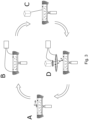
- the electron beam system 10 operates as Figure 3 evident as follows: First, in step A, the top loose layer 32 of powdered material is applied to the powder bed 24 using the powder application device 26. In the wake of the movement of the powder application device 26, excess powder is scraped off during the movement.
- step B the powder bed 24 is heated with the aid of the heating element 34 to just below or at the melting temperature of the material.
- step C the electron beam 16 is generated with the electron beam gun 14, which then specifies the 3D structure of the workpiece 80 to be created by locally selective melting of the powder particles and the subsequent solidification of the material.
- Locally selective melting means a point-by-point melting of the powdery material at the point of impact of the electron beam 16.
- the workpiece is then generated point by point, line by line and layer by layer.
- step D the electron beam 16 is then guided over the powder bed 24, in particular over the entire powder bed 24, and the backscattered electrons 42 are detected in the process.
- the evaluation and control unit 36 records the current detected by the backscattered electron detectors 38 and 40 and evaluates it.
- the evaluation and control unit 36 can obtain additional information by appropriately evaluating the different currents, for example in the four sectors of the backscattered electron detector 40 or between the two detectors 38 and 40.
- the evaluation and control unit 36 can obtain additional information by appropriately evaluating the different currents, for example in the four sectors of the backscattered electron detector 40 or between the two detectors 38 and 40.
Landscapes
- Engineering & Computer Science (AREA)
- Chemical & Material Sciences (AREA)
- Manufacturing & Machinery (AREA)
- Materials Engineering (AREA)
- Physics & Mathematics (AREA)
- Analytical Chemistry (AREA)
- General Physics & Mathematics (AREA)
- Biochemistry (AREA)
- Health & Medical Sciences (AREA)
- Life Sciences & Earth Sciences (AREA)
- Automation & Control Theory (AREA)
- General Health & Medical Sciences (AREA)
- Immunology (AREA)
- Pathology (AREA)
- Plasma & Fusion (AREA)
- Crystallography & Structural Chemistry (AREA)
- Human Computer Interaction (AREA)
- Powder Metallurgy (AREA)
Description
- Die Erfindung betrifft ein Verfahren zur additiven Herstellung eines Werkstücks.
- Die Erfindung betrifft ferner eine Elektronenstrahlanlage zur additiven Herstellung eines Werkstücks aus einem pulverförmigen Werkstoff.
- Additive Herstellungsprozesse von Werkstücken erfahren derzeit unter dem Stichwort 3D-Druck große Aufmerksamkeit. Dabei ist es bereits bekannt, mit einem Laserstrahl einen pulverförmigen Werkstoff wie beispielsweise ein Kunststoffgranulat in einem Werkstoffbett Schicht für Schicht punktweise selektiv zu schmelzen, sodass nach und nach aus dem geschmolzenen und danach wieder ausgehärteten Kunststoff ein zusammenhängendes Werkstück erhalten wird. Am Ende des additiven Herstellungsprozesses wird dieses Werkstück von dem noch pulverförmigen Rest des pulverförmigen Werkstoffs befreit.
- Zur Überwachung eines solchen Herstellungsprozesses ist aus der
EP 2 032 345 B1 zudem bekannt, eine Kamera einzusetzen, welche die Bearbeitungszone optisch überwacht. - Eine Bildauswertung kann dann durch Aufzeichnen einzelner Schichtbilder Schicht für Schicht erkennen, ob das Werkstück wie gewünscht voranschreitet. Durch Zusammenfügen der einzelnen Schichtbilder kann die Bildverarbeitung darüber hinaus von dem Werkstück ein tomographisches Bild erzeugen.
- Ferner ist es auch bekannt, sogenannte Elektronenstrahlanlagen, bei welchen in einem Vakuumgefäß ein Elektronenstrahl auf ein Werkstoffbett gerichtet wird, zur additiven Herstellung von Werkstücken zu verwenden.
- Hierbei hat sich jedoch herausgestellt, dass die Anwendung eines optischen Überwachungsverfahrens nicht zu zufriedenstellenden Ergebnissen führt.
- Aus
EP 2 832 473 A1 ,EP 2 832 475 A2 undEP 2 832 474 A1 sind daher Verfahren bekannt, bei welchen zeitgleich mit zwei Elektronenstrahlen gearbeitet wird. Ein erster Schmelz-Elektronenstrahl wird zum selektiven Schmelzen verwendet, wohingegen ein zweiter Scan-Elektronenstrahl auf die Oberfläche gerichtet wird und diese scannt. Die bei diesem Scannen entstehenden Rückstreuelektronen werden erfasst, um ein Bild der Oberfläche zu erzeugen. - Aus der
DE 10 2010 011 059 A1 und derCN 206 794 757 U gehen ähnliche Scanverfahren mit einem zweiten Elektronenstrahl hervor. - Aufgabe der Erfindung ist es daher, demgegenüber ein verbessertes Verfahren anzugeben.
- Aufgabe der Erfindung ist es ferner eine entsprechende Elektronenstrahlanlage anzugeben.
- Erfindungsgemäß wird diese Aufgabe durch ein Verfahren nach Anspruch 1 gelöst.
- Bei der additiven Herstellung von Werkstücken mit Hilfe von Elektronenstrahlanlagen werden typischerweise andere Materialien wie bei der Verwendung von Laserstrahlanlagen verwendet. Beispielsweise werden in Elektronenstrahlanlagen häufig Metalle oder Metalllegierungen verwendet.
- Der Erfinder hat dabei erkannt, dass beim Schmelzen mittels Elektronenstrahlen der bekannte Ansatz, eine Kamera einzusetzen, nicht anwendbar ist. Denn der zu verschmelzende Werkstoff im Pulverbett muss beim Elektronenstrahlschmelzen häufig vorerhitzt werden, um das Pulver bereits nahe an oder bis direkt an die Schmelztemperatur zu bringen. Ansonsten würde ein pulverförmiger Werkstoff aufgrund von elektrostatischer Absto-ßung und aufgrund der Prozessführung im Vakuum aus dem Pulverbett "verblasen".
- Der pulverförmige Werkstoff ist daher bereits rotglühend und würde sich von einem weißglühenden Schmelzpunkt optisch kaum unterscheiden bzw. würde die Dynamik einer optischen Erfassung überfordern. Auch kühlt sich das Werkstück im Vakuum nur langsam ab, sodass die Grenze zwischen Werkstück und pulverförmigem Werkstoff bei einer optischen Erfassung ohne längere Wartezeiten kaum erkennbar wäre.
- Der Erfinder hat ferner erkannt, dass ein Warten auf das Abkühlen des Werkstücks zur optischen Erfassung nicht anwendbar ist, da dann im Werkstück Gefügeänderungen auftreten, die nicht wünschenswert sind.
- Der Erfinder ist daher dazu übergegangen, die Rückstreuelektronen zur Überwachung des additiven Herstellungsprozesses heranzuziehen.
- Im Gegensatz zur optischen Erfassung einer gesamten Schicht mit einer einzelnen Aufnahme werden die Rückstreuelektronen jeweils nur an einem Punkt, dem Auftreffpunkt des Elektronenstrahls zurück gestreut. Daher liefert das erfindungsgemäße Verfahren erst durch eine entsprechende Scanbewegung eine der optischen Erfassung vergleichbares Bild.
- Insbesondere kann dabei die Intensität der Rückstreuelektronen, d.h. der Rückstreuelektronenstrom, ausgewertet werden.
- Insgesamt erlaubt das erfindungsgemäße Verfahren eine bessere Kontrolle des gesamten additiven Herstellungsprozesses bei der Verwendung eines Elektronenstrahls zum örtlich selektiven Schmelzen.
- Vorzugsweise kann durch das Auswerten die Dichte des Werkstücks bestimmt werden.
- Das Rückstreuverhalten der Elektronen wird stark durch die Dichte des Werkstoffes an dem jeweiligen Auftreffpunkt des Elektronenstrahls bestimmt. Daher eignet sich die Auswertung der erfassten Rückstreuelektronen besonders zur Bestimmung der Dichte des Werkstoffs. Dies ist ein besonderer Vorteil gegenüber der aus dem Herstellungsprozess mittels Laser bekannten optischen Erfassung, da dadurch eine innere Struktur des Werkstückmaterials bestimmt werden kann.
- Vorzugsweise kann durch das Auswerten der Rückstreuelektronen ein Schichtbild des Werkstücks erzeugt werden.
- Durch ein Erfassen der Rückstreuelektronen Schicht für Schicht während des additiven Herstellungsprozesses kann von dem erzeugten Werkstück eine Art tomographische Bild generiert werden. Da das Rückstreuverhalten der Elektronen vor allem von der Dichte des Werkstoffs abhängt, zeigt dieses Bild besonders vorteilhaft die Dichteverteilung innerhalb des Werkstücks.
- Vorzugsweise kann durch das Auswerten eine Änderung der Zusammensetzung des Werkstoffs bestimmt werden.
- Falls der Werkstoff für das Werkstück sich wie beispielsweise im Falle einer Legierung aus unterschiedlichen Komponenten zusammensetzt lässt sich auf diese Weise die Änderung der Legierung bestimmen, sofern sich diese Änderung auf das Rückstreuverhalten der Rückstreuelektronen auswirkt. So kann beispielsweise eine Legierung im ursprünglichen, pulverförmigen Werkstoff eine erste Dichte aufweisen und die geschmolzene und wieder erstarrte Legierung im Werkstück kann eine zweite Dichte aufweisen. Auch Änderungen der Zusammensetzung im Pulverbett können erkannt werden und beispielsweise zur Temperaturführung des Vorheizens verwendet werden. Insbesondere kann auch die Stickstoffverarmung eines Materials aufgrund des Schmelzvorgangs gemessen werden.
- Vorzugsweise kann durch das Auswerten der Rückstreuelektronen die Mikroporosität des Werkstücks bestimmt werden.
- Mit Hilfe entsprechender Parametrisierung des Elektronenstrahls und/oder der Temperaturführung des Pulverbetts kann ein mikroporöses Werkstück hergestellt werden, bei welchem die Pulverpartikel nur teilweise miteinander verschmolzen sind. Über das erfindungsgemäße Verfahren kann dabei die Mikroporosität überwacht werden. Davon unabhängig kann die Mikroporosität jedoch auch zur Überwachung eines vollständigen Schmelzprozesses verwendet werden, um eine möglichst geringe Mikroporosität des Werkstücks zu erhalten.
- Vorzugsweise kann durch das Auswerten die Oberflächenqualität des Bauteils bestimmt wird.
- Da die Rückstreuelektronen stark auf die Dichte des Werkstoffes reagieren, kann die Auswertung besonders gut den Übergang vom weniger Dichten pulverförmigen Werkstoff zum geschmolzenen und damit dichteren Werkstoff des Werkstücks erkennen. Insbesondere können dadurch Sinterhälse erkannt werden, die sich von einer Oberfläche des Werkstücks in das benachbarte heiße Pulver erstrecken. Dies ist beispielsweise von entscheidender Bedeutung zur Temperaturführung des Pulverbetts, um eine glatte Oberfläche zu erhalten.
- Denn der additive Herstellungsprozess mit Hilfe des Elektronenstrahls hat gerade gegenüber dem aus kaltem Pulver bauenden Laserprozess den Nachteil schlechterer Oberflächenqualität aufgrund des Vorheizens. Durch das erfindungsgemäße Verfahren kann man dennoch ein Werkstück mit einer qualitativ hochwertigeren Oberfläche erzeugen, wobei das Werkstück zugleich weniger Verspannungen als ein Werkstück aus einem Laserprozesses aufweist.
- Erfindungsgemäß erfolgt das Erfassen der Rückstreuelektronen während des Schmelzens. Da auch während des Schmelzvorgangs mit Hilfe des Elektronenstrahls Elektronen zurückgestreut werden, kann das Erfassen und Auswerten grundsätzlich auch zeitgleich am jeweiligen Schmelzpunkt erfolgen. Insbesondere kann die Dichte laufend während des Schmelzprozesses an dem jeweiligen Punkt gemessen werden.
- Das Erfassen und Auswerten kann jedoch zusätzlich auch beispielsweise mit einer verminderten Elektronenstrahlintensität nach dem eigentlichen Schmelzvorgang erfolgen. Dann kann auch eine Scanbewegung durchgeführt werden, um beispielsweise ein gesamtes Schichtbild zu erzeugen.
- Vorzugsweise kann das Ergebnis des Auswertens zur Prozesssteuerung verwendet werden. Ganz allgemein kann der gesamte additive Herstellungsprozess in Abhängigkeit der Auswertung der Rückstreuelektronen, insbesondere der oben genannten Auswertungen, geregelt werden. Zu den steuerbaren Prozessparametern zählt beispielsweise Temperatursteuerung für das Vorheizen des Pulvers, die Elektronenstahlintensität und/oder die Geschwindigkeit, mit welcher der Elektronenstrahl bewegt wird.
- Erfindungsgemäß erfolgt das Auswerten der Rückstreuelektronen richtungsabhängig mit Hilfe mehrerer an unterschiedlichen Orten angeordneten Rückstreuelektronendetektoren.
- Dazu kann zumindest einer der Detektoren beispielsweise zwischen 30° und 60° bezogen auf die senkrechte Rückstreurichtung seitlich angeordnet sein, um den Rückstreukegel richtungsabhängig zu erfassen. Ferner kann ein üblicherweise einstückiger Rückstreuelektronendetektor in mehrere Sektoren unterteilt sein. Dadurch kann man Schattenwurftopographien erzeugen, die für weitere Prozessteuerungen ausgewertet werden können.
- Diese richtungsabhängige Messung der Rückstreuelektronen kann auch unabhängig von dem hier erfindungsgemäßen additiven Herstellungsverfahren ganz allgemein bei der Elektronenstrahlbearbeitung zur Anwendung kommen.
- Hinsichtlich der Elektronenstrahlanlage wird die Aufgabe durch eine Elektronenstrahlanlage nach Anspruch 8 gelöst.
- Eine solche Elektronenstrahlanlage kann die oben beschriebenen Verfahren durchführen.
- Nachfolgend werden Ausführungsbeispiele der Erfindung anhand der Zeichnungen näher erläutert. In diesen zeigen:
- Figur 1
- eine perspektivische Ansicht einer erfindungsgemäßen Elektronenstrahlanlage zur additiven Herstellung eines Werkstücks mit einem Rückstreuelektronenstrahldetektor und einer Auswerteeinheit;
- Figur 2
- eine Schnittansicht der Elektronenstrahlanlage aus
Figur 2 ; - Figur 3
- eine schematische Darstellung der Abfolge eines erfindungsgemäßen Verfahrens zur additiven Herstellung eines Werkstücks mit einem Schritt zur Erfassung und Auswertung der Rückstreuelektronen.
-
Figur 1 zeigt eine Elektronenstrahlanlage 10 mit einem Vakuumgehäuse 12, in welchem eine Elektronenstrahlkanone 14 zur Erzeugung eines Elektronenstrahls 16 angeordnet ist. - Im vorliegenden Ausführungsbeispiel ist die Elektronenstrahlkanone 14 oberhalb eines Hubtisches 18 mit einer elektrisch leitfähigen Hubplatte 20 und mit einem Aufnahmerahmen 22 angeordnet, der als räumlich begrenztes Pulverbehältnis dient, welches ein Pulverbett 24 aus einem zu bearbeitenden pulverförmigen Werkstoff aufnimmt.
- Wird die Hubplatte 20 nach unten gefahren, kann das Pulverbett 24 nach und nach einen größer werdenden Bereich einnehmen, sodass das Pulverbett 24 Schicht für Schicht vergrößert wird.
- Oberhalb des Aufnahmerahmens 22 ist dazu eine Pulverauftrageinrichtung 26 mit einer Rakel 28 angeordnet, die mit einer Verfahreinrichtung 30 über den Hubtisch 18 bewegt werden kann. Die Pulverauftrageinrichtung 26 weist einen nicht gezeigten Behälter für den pulverförmigen Werkstoff auf, aus welchem durch eine Verfahrbewegung jeweils als oberste lose Schicht 32 der Werkstoff auf dem Pulverbett 24 eben aufgerakelt werden kann.
- Über ein in
Figur 2 ersichtliches Heizelement 34 am oberen Rand des Aufnahmerahmens 22 kann das Pulverbett 24 erwärmt werden. - Mit dem Bezugszeichen 80 ist in
Figur 1 ferner ein beispielhaft als Stern dargestelltes Werkstück bezeichnet, das durch Verschmelzen einzelner Partikel im Pulverbett 22 mit Hilfe des Elektronenstrahls 16 nach und nach ausgebildet bzw. "gedruckt" wurde. - Aus
Figur 2 ist dabei ersichtlich, dass das Werkstück 80 auch in senkrechter Richtung zur horizontalen Fläche des Pulverbetts 22 mit Ausnehmungen und Wölbungen komplexer strukturiert ist. - Zudem sind dort am Werkstück 80 beispielhaft kleinere Sinterhälse 82 gezeigt, welche aus der ansonsten glatten Oberfläche des Werkstücks 80 hervorstehen.
- Ferner ist ein mikroporöser Bereich 84 des Werkstücks 80 gezeigt, in welchem nur eine teilweise Verschmelzung der Pulverpartikel erfolgte.
- Die Elektronenstrahlanlage 10 weist außerdem eine Auswerte- und Steuerungseinheit 36 auf, welche elektrisch mit zwei Rückstreuelektronendetektoren 38 und 40 verbunden ist.
- Im einfachsten hier gezeigten Fall sind die Rückstreuelektronendetektoren 38 und 40 konzentrisch um die Hauptachse des Elektronenstrahls 16 herum angeordnete Metallringe unterschiedlichen Durchmessers. Der Rückstreuelektronendetektor 40 ist dabei in vier Sektoren unterteilt, welche (hier nicht explizit dargestellt) jeweils einzeln elektrisch mit der Auswerte- und Steuerungseinheit 36 verbunden sind.
- Wie aus
Figur 2 ersichtlich ist, können mit Hilfe der Rückstreuelektronendetektoren 36 und 38 sogenannte Rückstreuelektronen 42 detektiert werden, die aufgrund des Elektroneneintrages durch den Elektronenstrahl 16 vom Pulverbett 24 oder dem Werkstück 80 zurückgestreut werden. - Die Auswerte- und Steuerungseinheit 36 ist dann dazu eingerichtet, verschiedene Eigenschaften des pulverförmigen Werkstoffs im Pulverbett 24 oder des Werkstücks 80 zu bestimmen.
- Zudem kann die Auswerte- und Steuerungseinheit 36 diese Information dazu nutzen, den additiven Herstellungsprozess zu steuern. Dazu ist die Auswerte- und Steuerungseinheit 36 beispielsweise elektrisch mit dem Heizelement 34 zum Erwärmen des Pulverbetts 24 verbunden.
- Die erfindungsgemäße Elektronenstrahlanlage 10 arbeitet wie aus
Figur 3 ersichtlich wie folgt:
Zunächst wird im Schritt A mit der Pulverauftrageinrichtung 26 die oberste lose Schicht 32 aus pulverförmigem Werkstoff auf dem Pulverbett 24 aufgetragen. Im Nachlauf zur Bewegung der Pulverauftrageinrichtung 26 wird dabei noch während der Bewegung überschüssiges Pulver abgerakelt. - Anschließend bzw. zugleich wird entsprechend Schritt B das Pulverbett 24 dabei mit Hilfe des Heizelements 34 bis knapp unter oder an die Schmelztemperatur des Werkstoffs erhitzt.
- Dann wird im Schritt C mit der Elektronenstrahlkanone 14 der Elektronenstrahl 16 erzeugt, der dann durch örtlich selektives Schmelzen der Pulverpartikel und das anschließende Erstarren des Werkstoffs die zu erzeugende 3D-Struktur des Werkstücks 80 vorgibt. Örtlich selektives Schmelzen bedeutet dabei ein punktuelles Verschmelzen des pulverförmigen Werkstoffes am Auftreffort des Elektronenstrahls 16. Je nach Scan-Strategie wird das Werkstück dann Punkt für Punkt, Linie für Linie und Schicht für Schicht erzeugt.
- Im Schritt D wird dann der Elektronenstrahl 16 über das Pulverbett 24, insbesondere über das gesamte Pulverbett 24, geführt und dabei die Rückstreuelektronen 42 erfasst. Hierzu zeichnet die Auswerte- und Steuerungseinheit 36 den von den Rückstreuelektronendetektoren 38 und 40 erfassten Strom auf und wertet diesen aus.
- Dadurch können verschiedene Eigenschaften sowohl des Pulverbetts 24 und/oder des Werkstücks 80 bestimmt werden. Hierzu gehört insbesondere die Bestimmung der Dichte des Werkstoffes und/oder des Werkstücks 80, der Oberflächenqualität des Werkstücks 80, des Vorhandenseins von Sinterhälsen 82, der Mikroporosität des Werkstücks 80, der Zusammensetzung des Werkstoffs und/oder anderer Eigenschaften.
- Die oben beschriebenen Schritte A bis D werden jeweils Schicht um Schicht wiederholt bis die 3D-Struktur 80 beendet ist.
- Da die Rückstreuelektronen 42 beispielsweise je nach Ausrichtung einer Oberfläche des Werkstücks 80 in unterschiedlich Richtungen unterschiedlich stark rückgestreut werden, kann die Auswerte- und Steuerungseinheit 36 durch entsprechende Auswertung der unterschiedlichen Ströme beispielsweise in den vier Sektoren des Rückstreuelektronendetektors 40 oder zwischen den beiden Detektoren 38 und 40 zusätzliche Informationen erhalten.
- Dadurch können verschiedene Eigenschaften sowohl des Pulverbetts 24 und/oder des Werkstücks 80 bestimmt werden. Hierzu gehört insbesondere die Bestimmung der Dichte des Werkstoffes und/oder des Werkstücks 80, der Oberflächenqualität des Werkstücks 80, des Vorhandenseins von Sinterhälsen 82, der Mikroporosität des Werkstücks 80, der Zusammensetzung des Werkstoffs und/oder anderer Eigenschaften.
- Die oben beschriebenen Schritte A bis D werden jeweils Schicht um Schicht wiederholt bis die 3D-Struktur 80 beendet ist.
- Da die Rückstreuelektronen 42 beispielsweise je nach Ausrichtung einer Oberfläche des Werkstücks 80 in unterschiedlich Richtungen unterschiedlich stark rückgestreut werden, kann die Auswerte- und Steuerungseinheit 36 durch entsprechende Auswertung der unterschiedlichen Ströme beispielsweise in den vier Sektoren des Rückstreuelektronendetektors 40 oder zwischen den beiden Detektoren 38 und 40 zusätzliche Informationen erhalten.
Claims (8)
- Verfahren zur additiven Herstellung eines Werkstücks (80) mit folgenden Schritten:a) Bereitstellen eines pulverförmigen Werkstoffes in einem Pulverbett (24) in einer Elektronenstrahlanlage (10) umfassend einen einzelnen Elektronenstrahlerzeuger (14), der dazu eingerichtet ist, einen Elektronenstrahl (16) auf lateral unterschiedliche Orte des Pulverbetts (24) zu richten, um dort örtlich selektiv den pulverförmigen Werkstoff zu schmelzen;b) Örtlich selektives Schmelzen des Werkstoffes im Pulverbett (24) mit dem bewegten Elektronenstrahl (16);c) Erfassen von Rückstreuelektronen (42), die von dem Werkstoff oder dem Werkstück (80) zurückgestreut werden, mit einem Rückstreuelektronendetektor (38, 40);d) Auswerten der Rückstreuelektronen (42) mit einer Auswerteeinheit (36);
dadurch gekennzeichnet, dasse) das Erfassen der Rückstreuelektronen (42), die aufgrund des Elektroneneintrages durch den Elektronenstrahl (16) zurückgestreut werden, während des Schmelzens und das Auswerten der Rückstreuelektronen (42) richtungsabhängig mit Hilfe mehrerer an unterschiedlichen Orten angeordneten Rückstreuelektronendetektoren (38; 40) erfolgt. - Verfahren nach Anspruch 1, dadurch gekennzeichnet, dass durch das Auswerten der Rückstreuelektronen (42) die Dichte des Werkstücks (80) und/oder des pulverförmigen Werkstoffes bestimmt wird.
- Verfahren nach einem der vorhergehenden Ansprüche, dadurch gekennzeichnet, dass durch Auswerten der Rückstreuelektronen (42) ein Schichtbild des Werkstücks (80) und/oder des pulverförmigen Werkstoffes erzeugt wird.
- Verfahren nach einem der vorhergehenden Ansprüche, dadurch gekennzeichnet, dass durch das Auswerten der Rückstreuelektronen (42) eine Änderung der Zusammensetzung des Werkstoffs bestimmt wird.
- Verfahren nach einem der vorhergehenden Ansprüche, dadurch gekennzeichnet, dass durch das Auswerten der Rückstreuelektronen (42) die Mikroporosität des Werkstücks (80) bestimmt wird.
- Verfahren nach einem der vorhergehenden Ansprüche, dadurch gekennzeichnet, dass durch das Auswerten der Rückstreuelektronen (42) die Oberflächenqualität des Werkstücks (80) bestimmt wird.
- Verfahren nach einem der vorhergehenden Ansprüche, dadurch gekennzeichnet, dass das Ergebnis des Auswertens zur Prozesssteuerung verwendet wird.
- Elektronenstrahlanlage (10) zur additiven Herstellung eines Werkstücks (80) aus einem pulverförmigen Werkstoff mita) einem Behältnis (20, 22) zur Aufnahme eines pulverförmigen Werkstoffes in einem Pulverbett (24),b) einem einzelnen Elektronenstrahlerzeuger (14), der dazu eingerichtet ist, einen Elektronenstrahl (16) auf lateral unterschiedliche Orte des Pulverbetts (24) zu richten, um dort örtlich selektiv den pulverförmigen Werkstoff zu schmelzen,
dadurch gekennzeichnet, dassc) die Elektronenstrahlanlage (10) eine Auswerteeinheit (36) und mehrere an unterschiedlichen Orten angeordnete Rückstreuelektronendetektoren (38, 40) aufweist, die dazu eingerichtet sind, Rückstreuelektronen (42), die von dem Werkstoff oder dem Werkstück (80) aufgrund des Elektroneneintrages durch den Elektronenstrahl (16) zurückgestreut werden, während des Schmelzens zu erfassen und richtungsabhängig mit Hilfe der Rückstreuelektronendetektoren (38, 40) auszuwerten.
Applications Claiming Priority (2)
| Application Number | Priority Date | Filing Date | Title |
|---|---|---|---|
| DE102018102082.1A DE102018102082A1 (de) | 2018-01-30 | 2018-01-30 | Verfahren und Elektronenstrahlanlage zur additiven Herstellung eines Werkstücks |
| PCT/EP2019/052066 WO2019149678A1 (de) | 2018-01-30 | 2019-01-29 | Verfahren und elektronenstrahlanlage zur additiven herstellung eines werkstücks |
Publications (2)
| Publication Number | Publication Date |
|---|---|
| EP3746776A1 EP3746776A1 (de) | 2020-12-09 |
| EP3746776B1 true EP3746776B1 (de) | 2025-01-29 |
Family
ID=65279528
Family Applications (1)
| Application Number | Title | Priority Date | Filing Date |
|---|---|---|---|
| EP19703265.9A Active EP3746776B1 (de) | 2018-01-30 | 2019-01-29 | Verfahren und elektronenstrahlanlage zur additiven herstellung eines werkstücks |
Country Status (3)
| Country | Link |
|---|---|
| EP (1) | EP3746776B1 (de) |
| DE (1) | DE102018102082A1 (de) |
| WO (1) | WO2019149678A1 (de) |
Families Citing this family (4)
| Publication number | Priority date | Publication date | Assignee | Title |
|---|---|---|---|---|
| JP6954963B2 (ja) * | 2019-09-09 | 2021-10-27 | 日本電子株式会社 | 3次元積層造形方法及び3次元積層造形装置 |
| EP3936262A1 (de) * | 2020-07-09 | 2022-01-12 | Stephanie Ness | Verfahren zur schichtweisen fertigung eines dreidimensionalen objekts, mit gezielter beleuchtung von kornrändern |
| SE546275C2 (en) | 2023-01-20 | 2024-09-17 | Freemelt Ab | Powder smoke detection during additive manufacturing |
| JP7736733B2 (ja) * | 2023-04-10 | 2025-09-09 | 日本電子株式会社 | 3次元積層造形装置及び3次元積層造形装置の制御方法 |
Family Cites Families (6)
| Publication number | Priority date | Publication date | Assignee | Title |
|---|---|---|---|---|
| US20090206065A1 (en) | 2006-06-20 | 2009-08-20 | Jean-Pierre Kruth | Procedure and apparatus for in-situ monitoring and feedback control of selective laser powder processing |
| DE102010011059A1 (de) * | 2010-03-11 | 2011-09-15 | Global Beam Technologies Ag | Verfahren und Vorrichtung zur Herstellung eines Bauteils |
| GB201313841D0 (en) * | 2013-08-02 | 2013-09-18 | Rolls Royce Plc | Method of Manufacturing a Component |
| GB201313839D0 (en) * | 2013-08-02 | 2013-09-18 | Rolls Royce Plc | Method of Manufacturing a Component |
| GB201313840D0 (en) * | 2013-08-02 | 2013-09-18 | Rolls Royce Plc | Method of Manufacturing a Component |
| CN206794757U (zh) * | 2017-06-06 | 2017-12-26 | 清华大学天津高端装备研究院 | 增材制造装置 |
-
2018
- 2018-01-30 DE DE102018102082.1A patent/DE102018102082A1/de active Pending
-
2019
- 2019-01-29 EP EP19703265.9A patent/EP3746776B1/de active Active
- 2019-01-29 WO PCT/EP2019/052066 patent/WO2019149678A1/de not_active Ceased
Also Published As
| Publication number | Publication date |
|---|---|
| WO2019149678A1 (de) | 2019-08-08 |
| DE102018102082A1 (de) | 2019-08-01 |
| EP3746776A1 (de) | 2020-12-09 |
Similar Documents
| Publication | Publication Date | Title |
|---|---|---|
| EP2964449B1 (de) | Verfahren und vorrichtung zur qualitätsbeurteilung eines mittels eines generativen lasersinter- und/oder laserschmelzverfahrens hergestellten bauteils | |
| EP3095591B1 (de) | Verfahren und vorrichtung zum zumindest bereichsweisen ermitteln einer kontur wenigstens einer generativ hergestellten bauteilschicht | |
| DE102013215362B4 (de) | Verfahren, Computerprogrammprodukt und Vorrichtung zum Bestimmen einer Einschweißtiefe beim Laserschweißen | |
| EP2712692B1 (de) | Verfahren und Vorrichtung zur Herstellung eines Bauteils | |
| EP1940575B1 (de) | SCHICHTWEISES HERSTELLUNGSVERFAHREN MIT KORNGRÖßENBEEINFLUSSUNG | |
| DE102014212246B3 (de) | Verfahren und Vorrichtung zur Qualitätssicherung | |
| DE10165113B3 (de) | Verfahren und Vorrichtung zur Herstellung eines Formkörpers | |
| DE102010061227A1 (de) | Vorrichtung zur Erzeugung von Röntgenstrahlen und Verfahren zur Herstellung der Vorrichtung | |
| EP3909750B1 (de) | Verfahren zur additiven herstellung dreidimensionaler objekte | |
| DE102018200566B4 (de) | System und Verfahren zur Überwachung der Fertigungsgenauigkeit bei der additiven Herstellung dreidimensionaler Bauteile | |
| WO2019149678A1 (de) | Verfahren und elektronenstrahlanlage zur additiven herstellung eines werkstücks | |
| EP3192598B1 (de) | Verfahren und vorrichtung zum ermitteln einer konzentration wenigstens eines werkstoffs in einem gesinterten oder geschmolzenen pulvergemisch für ein additives herstellverfahren | |
| EP3082102A1 (de) | Verfahren zum evaluieren wenigstens einer mittels eines generativen pulverschichtverfahrens hergestellten bauteilschicht | |
| DE102017130282A1 (de) | Verfahren und Vorrichtung zum additiven Herstellen eines Bauteil sowie Bauteil | |
| DE102007032190A1 (de) | Verfahren zum Behandeln der Oberfläche eines Werkstückes unter Hitzeanwendung und Vorrichtung zur Durchführung des Verfahrens | |
| EP3488305A1 (de) | Verfahren und vorrichtung zur ermittlung der bauteilqualität | |
| DE102015224395A1 (de) | Vorrichtung und Verfahren zum Herstellen eines Bauteils in Schichtbauweise, Verwendung einer Erfassungseinrichtung in einem Schichtbauverfahren | |
| DE102024001049A1 (de) | Verfahren zur Qualitätssicherung beim Laserstrahlschweißen von mindestens zwei Bauteilen und eine Schweißvorrichtung hierfür | |
| EP3323597B1 (de) | Vorrichtung und verfahren zur additiven herstellung eines dreidimensionalen produktes | |
| DE102020213969A1 (de) | Dreidimensionale Fertigungsvorrichtung und Dreidimensionales Fertigungsverfahren | |
| DE102016211935B4 (de) | Vorrichtung und Verfahren zur Prozessüberwachung bei einem Auftragschweiß-Verfahren | |
| DE10338062B4 (de) | Verfahren zur Qualitätskontrolle von thermischen Fügeverfahren | |
| EP3685991A1 (de) | Herstellen eines bauteils | |
| WO2017009093A1 (de) | Vakuum sls verfahren zur additiven herstellung von metallischen bauteilen | |
| DE102018127987A1 (de) | Verfahren zur Bauteilvermessung eines additiv hergestellten Objekts mit definiertem Energieeintrag |
Legal Events
| Date | Code | Title | Description |
|---|---|---|---|
| STAA | Information on the status of an ep patent application or granted ep patent |
Free format text: STATUS: UNKNOWN |
|
| STAA | Information on the status of an ep patent application or granted ep patent |
Free format text: STATUS: THE INTERNATIONAL PUBLICATION HAS BEEN MADE |
|
| PUAI | Public reference made under article 153(3) epc to a published international application that has entered the european phase |
Free format text: ORIGINAL CODE: 0009012 |
|
| STAA | Information on the status of an ep patent application or granted ep patent |
Free format text: STATUS: REQUEST FOR EXAMINATION WAS MADE |
|
| 17P | Request for examination filed |
Effective date: 20200709 |
|
| AK | Designated contracting states |
Kind code of ref document: A1 Designated state(s): AL AT BE BG CH CY CZ DE DK EE ES FI FR GB GR HR HU IE IS IT LI LT LU LV MC MK MT NL NO PL PT RO RS SE SI SK SM TR |
|
| AX | Request for extension of the european patent |
Extension state: BA ME |
|
| DAV | Request for validation of the european patent (deleted) | ||
| DAX | Request for extension of the european patent (deleted) | ||
| REG | Reference to a national code |
Ref country code: DE Ref legal event code: R079 Free format text: PREVIOUS MAIN CLASS: G01N0023203000 Ipc: B22F0010280000 Ref document number: 502019012880 Country of ref document: DE |
|
| RIC1 | Information provided on ipc code assigned before grant |
Ipc: B22F 12/67 20210101ALN20240729BHEP Ipc: B22F 12/13 20210101ALN20240729BHEP Ipc: B22F 10/36 20210101ALN20240729BHEP Ipc: B22F 12/90 20210101ALI20240729BHEP Ipc: G05B 19/4099 20060101ALI20240729BHEP Ipc: G01N 23/2251 20180101ALI20240729BHEP Ipc: G01N 23/203 20060101ALI20240729BHEP Ipc: B33Y 50/02 20150101ALI20240729BHEP Ipc: B33Y 50/00 20150101ALI20240729BHEP Ipc: B33Y 30/00 20150101ALI20240729BHEP Ipc: B33Y 10/00 20150101ALI20240729BHEP Ipc: B22F 10/28 20210101AFI20240729BHEP |
|
| GRAP | Despatch of communication of intention to grant a patent |
Free format text: ORIGINAL CODE: EPIDOSNIGR1 |
|
| STAA | Information on the status of an ep patent application or granted ep patent |
Free format text: STATUS: GRANT OF PATENT IS INTENDED |
|
| INTG | Intention to grant announced |
Effective date: 20240909 |
|
| GRAS | Grant fee paid |
Free format text: ORIGINAL CODE: EPIDOSNIGR3 |
|
| GRAA | (expected) grant |
Free format text: ORIGINAL CODE: 0009210 |
|
| STAA | Information on the status of an ep patent application or granted ep patent |
Free format text: STATUS: THE PATENT HAS BEEN GRANTED |
|
| AK | Designated contracting states |
Kind code of ref document: B1 Designated state(s): AL AT BE BG CH CY CZ DE DK EE ES FI FR GB GR HR HU IE IS IT LI LT LU LV MC MK MT NL NO PL PT RO RS SE SI SK SM TR |
|
| P01 | Opt-out of the competence of the unified patent court (upc) registered |
Free format text: CASE NUMBER: APP_67584/2024 Effective date: 20241220 |
|
| REG | Reference to a national code |
Ref country code: GB Ref legal event code: FG4D Free format text: NOT ENGLISH |
|
| REG | Reference to a national code |
Ref country code: CH Ref legal event code: EP |
|
| REG | Reference to a national code |
Ref country code: DE Ref legal event code: R096 Ref document number: 502019012880 Country of ref document: DE |
|
| REG | Reference to a national code |
Ref country code: IE Ref legal event code: FG4D Free format text: LANGUAGE OF EP DOCUMENT: GERMAN |
|
| REG | Reference to a national code |
Ref country code: SE Ref legal event code: TRGR |
|
| REG | Reference to a national code |
Ref country code: NL Ref legal event code: MP Effective date: 20250129 |
|
| PG25 | Lapsed in a contracting state [announced via postgrant information from national office to epo] |
Ref country code: NL Free format text: LAPSE BECAUSE OF FAILURE TO SUBMIT A TRANSLATION OF THE DESCRIPTION OR TO PAY THE FEE WITHIN THE PRESCRIBED TIME-LIMIT Effective date: 20250129 |
|
| PG25 | Lapsed in a contracting state [announced via postgrant information from national office to epo] |
Ref country code: RS Free format text: LAPSE BECAUSE OF FAILURE TO SUBMIT A TRANSLATION OF THE DESCRIPTION OR TO PAY THE FEE WITHIN THE PRESCRIBED TIME-LIMIT Effective date: 20250429 |
|
| PG25 | Lapsed in a contracting state [announced via postgrant information from national office to epo] |
Ref country code: FI Free format text: LAPSE BECAUSE OF FAILURE TO SUBMIT A TRANSLATION OF THE DESCRIPTION OR TO PAY THE FEE WITHIN THE PRESCRIBED TIME-LIMIT Effective date: 20250129 |
|
| PG25 | Lapsed in a contracting state [announced via postgrant information from national office to epo] |
Ref country code: PL Free format text: LAPSE BECAUSE OF FAILURE TO SUBMIT A TRANSLATION OF THE DESCRIPTION OR TO PAY THE FEE WITHIN THE PRESCRIBED TIME-LIMIT Effective date: 20250129 |
|
| PG25 | Lapsed in a contracting state [announced via postgrant information from national office to epo] |
Ref country code: ES Free format text: LAPSE BECAUSE OF FAILURE TO SUBMIT A TRANSLATION OF THE DESCRIPTION OR TO PAY THE FEE WITHIN THE PRESCRIBED TIME-LIMIT Effective date: 20250129 |
|
| REG | Reference to a national code |
Ref country code: LT Ref legal event code: MG9D |
|
| PG25 | Lapsed in a contracting state [announced via postgrant information from national office to epo] |
Ref country code: NO Free format text: LAPSE BECAUSE OF FAILURE TO SUBMIT A TRANSLATION OF THE DESCRIPTION OR TO PAY THE FEE WITHIN THE PRESCRIBED TIME-LIMIT Effective date: 20250429 Ref country code: IS Free format text: LAPSE BECAUSE OF FAILURE TO SUBMIT A TRANSLATION OF THE DESCRIPTION OR TO PAY THE FEE WITHIN THE PRESCRIBED TIME-LIMIT Effective date: 20250529 |
|
| PG25 | Lapsed in a contracting state [announced via postgrant information from national office to epo] |
Ref country code: HR Free format text: LAPSE BECAUSE OF FAILURE TO SUBMIT A TRANSLATION OF THE DESCRIPTION OR TO PAY THE FEE WITHIN THE PRESCRIBED TIME-LIMIT Effective date: 20250129 |
|
| PG25 | Lapsed in a contracting state [announced via postgrant information from national office to epo] |
Ref country code: PT Free format text: LAPSE BECAUSE OF FAILURE TO SUBMIT A TRANSLATION OF THE DESCRIPTION OR TO PAY THE FEE WITHIN THE PRESCRIBED TIME-LIMIT Effective date: 20250529 Ref country code: LV Free format text: LAPSE BECAUSE OF FAILURE TO SUBMIT A TRANSLATION OF THE DESCRIPTION OR TO PAY THE FEE WITHIN THE PRESCRIBED TIME-LIMIT Effective date: 20250129 |
|
| PG25 | Lapsed in a contracting state [announced via postgrant information from national office to epo] |
Ref country code: BG Free format text: LAPSE BECAUSE OF FAILURE TO SUBMIT A TRANSLATION OF THE DESCRIPTION OR TO PAY THE FEE WITHIN THE PRESCRIBED TIME-LIMIT Effective date: 20250129 Ref country code: GR Free format text: LAPSE BECAUSE OF FAILURE TO SUBMIT A TRANSLATION OF THE DESCRIPTION OR TO PAY THE FEE WITHIN THE PRESCRIBED TIME-LIMIT Effective date: 20250430 |
|
| REG | Reference to a national code |
Ref country code: CH Ref legal event code: PL |
|
| PG25 | Lapsed in a contracting state [announced via postgrant information from national office to epo] |
Ref country code: LU Free format text: LAPSE BECAUSE OF NON-PAYMENT OF DUE FEES Effective date: 20250129 |
|
| PG25 | Lapsed in a contracting state [announced via postgrant information from national office to epo] |
Ref country code: SM Free format text: LAPSE BECAUSE OF FAILURE TO SUBMIT A TRANSLATION OF THE DESCRIPTION OR TO PAY THE FEE WITHIN THE PRESCRIBED TIME-LIMIT Effective date: 20250129 |
|
| PG25 | Lapsed in a contracting state [announced via postgrant information from national office to epo] |
Ref country code: DK Free format text: LAPSE BECAUSE OF FAILURE TO SUBMIT A TRANSLATION OF THE DESCRIPTION OR TO PAY THE FEE WITHIN THE PRESCRIBED TIME-LIMIT Effective date: 20250129 |
|
| PG25 | Lapsed in a contracting state [announced via postgrant information from national office to epo] |
Ref country code: MC Free format text: LAPSE BECAUSE OF FAILURE TO SUBMIT A TRANSLATION OF THE DESCRIPTION OR TO PAY THE FEE WITHIN THE PRESCRIBED TIME-LIMIT Effective date: 20250129 |
|
| PG25 | Lapsed in a contracting state [announced via postgrant information from national office to epo] |
Ref country code: IT Free format text: LAPSE BECAUSE OF FAILURE TO SUBMIT A TRANSLATION OF THE DESCRIPTION OR TO PAY THE FEE WITHIN THE PRESCRIBED TIME-LIMIT Effective date: 20250129 |
|
| PG25 | Lapsed in a contracting state [announced via postgrant information from national office to epo] |
Ref country code: BE Free format text: LAPSE BECAUSE OF NON-PAYMENT OF DUE FEES Effective date: 20250131 |
|
| PG25 | Lapsed in a contracting state [announced via postgrant information from national office to epo] |
Ref country code: CH Free format text: LAPSE BECAUSE OF NON-PAYMENT OF DUE FEES Effective date: 20250131 |
|
| PG25 | Lapsed in a contracting state [announced via postgrant information from national office to epo] |
Ref country code: CZ Free format text: LAPSE BECAUSE OF FAILURE TO SUBMIT A TRANSLATION OF THE DESCRIPTION OR TO PAY THE FEE WITHIN THE PRESCRIBED TIME-LIMIT Effective date: 20250129 Ref country code: EE Free format text: LAPSE BECAUSE OF FAILURE TO SUBMIT A TRANSLATION OF THE DESCRIPTION OR TO PAY THE FEE WITHIN THE PRESCRIBED TIME-LIMIT Effective date: 20250129 |
|
| REG | Reference to a national code |
Ref country code: BE Ref legal event code: MM Effective date: 20250131 |
|
| PG25 | Lapsed in a contracting state [announced via postgrant information from national office to epo] |
Ref country code: RO Free format text: LAPSE BECAUSE OF FAILURE TO SUBMIT A TRANSLATION OF THE DESCRIPTION OR TO PAY THE FEE WITHIN THE PRESCRIBED TIME-LIMIT Effective date: 20250129 |
|
| PG25 | Lapsed in a contracting state [announced via postgrant information from national office to epo] |
Ref country code: SK Free format text: LAPSE BECAUSE OF FAILURE TO SUBMIT A TRANSLATION OF THE DESCRIPTION OR TO PAY THE FEE WITHIN THE PRESCRIBED TIME-LIMIT Effective date: 20250129 |
|
| REG | Reference to a national code |
Ref country code: DE Ref legal event code: R097 Ref document number: 502019012880 Country of ref document: DE |
|
| PLBE | No opposition filed within time limit |
Free format text: ORIGINAL CODE: 0009261 |
|
| STAA | Information on the status of an ep patent application or granted ep patent |
Free format text: STATUS: NO OPPOSITION FILED WITHIN TIME LIMIT |
|
| 26N | No opposition filed |
Effective date: 20251030 |
|
| PG25 | Lapsed in a contracting state [announced via postgrant information from national office to epo] |
Ref country code: IE Free format text: LAPSE BECAUSE OF NON-PAYMENT OF DUE FEES Effective date: 20250129 |
|
| PGFP | Annual fee paid to national office [announced via postgrant information from national office to epo] |
Ref country code: SE Payment date: 20260107 Year of fee payment: 8 |
|
| PGFP | Annual fee paid to national office [announced via postgrant information from national office to epo] |
Ref country code: GB Payment date: 20260113 Year of fee payment: 8 |
|
| PGFP | Annual fee paid to national office [announced via postgrant information from national office to epo] |
Ref country code: DE Payment date: 20260108 Year of fee payment: 8 |
|
| PGFP | Annual fee paid to national office [announced via postgrant information from national office to epo] |
Ref country code: AT Payment date: 20260108 Year of fee payment: 8 |
|
| PGFP | Annual fee paid to national office [announced via postgrant information from national office to epo] |
Ref country code: FR Payment date: 20260113 Year of fee payment: 8 |