EP3746830B1 - Optical system of a stereo-video endoscope - Google Patents
Optical system of a stereo-video endoscope Download PDFInfo
- Publication number
- EP3746830B1 EP3746830B1 EP19702368.2A EP19702368A EP3746830B1 EP 3746830 B1 EP3746830 B1 EP 3746830B1 EP 19702368 A EP19702368 A EP 19702368A EP 3746830 B1 EP3746830 B1 EP 3746830B1
- Authority
- EP
- European Patent Office
- Prior art keywords
- lens
- light
- coating
- outlet
- optical system
- Prior art date
- Legal status (The legal status is an assumption and is not a legal conclusion. Google has not performed a legal analysis and makes no representation as to the accuracy of the status listed.)
- Active
Links
Images

Classifications
-
- G—PHYSICS
- G02—OPTICS
- G02B—OPTICAL ELEMENTS, SYSTEMS OR APPARATUS
- G02B23/00—Telescopes, e.g. binoculars; Periscopes; Instruments for viewing the inside of hollow bodies; Viewfinders; Optical aiming or sighting devices
- G02B23/24—Instruments or systems for viewing the inside of hollow bodies, e.g. fibrescopes
- G02B23/2407—Optical details
- G02B23/2423—Optical details of the distal end
- G02B23/243—Objectives for endoscopes
-
- A—HUMAN NECESSITIES
- A61—MEDICAL OR VETERINARY SCIENCE; HYGIENE
- A61B—DIAGNOSIS; SURGERY; IDENTIFICATION
- A61B1/00—Instruments for performing medical examinations of the interior of cavities or tubes of the body by visual or photographical inspection, e.g. endoscopes; Illuminating arrangements therefor
- A61B1/00064—Constructional details of the endoscope body
- A61B1/00066—Proximal part of endoscope body, e.g. handles
-
- A—HUMAN NECESSITIES
- A61—MEDICAL OR VETERINARY SCIENCE; HYGIENE
- A61B—DIAGNOSIS; SURGERY; IDENTIFICATION
- A61B1/00—Instruments for performing medical examinations of the interior of cavities or tubes of the body by visual or photographical inspection, e.g. endoscopes; Illuminating arrangements therefor
- A61B1/00064—Constructional details of the endoscope body
- A61B1/00071—Insertion part of the endoscope body
- A61B1/0008—Insertion part of the endoscope body characterised by distal tip features
- A61B1/00096—Optical elements
-
- A—HUMAN NECESSITIES
- A61—MEDICAL OR VETERINARY SCIENCE; HYGIENE
- A61B—DIAGNOSIS; SURGERY; IDENTIFICATION
- A61B1/00—Instruments for performing medical examinations of the interior of cavities or tubes of the body by visual or photographical inspection, e.g. endoscopes; Illuminating arrangements therefor
- A61B1/00163—Optical arrangements
- A61B1/00174—Optical arrangements characterised by the viewing angles
- A61B1/00183—Optical arrangements characterised by the viewing angles for variable viewing angles
-
- A—HUMAN NECESSITIES
- A61—MEDICAL OR VETERINARY SCIENCE; HYGIENE
- A61B—DIAGNOSIS; SURGERY; IDENTIFICATION
- A61B1/00—Instruments for performing medical examinations of the interior of cavities or tubes of the body by visual or photographical inspection, e.g. endoscopes; Illuminating arrangements therefor
- A61B1/00163—Optical arrangements
- A61B1/00193—Optical arrangements adapted for stereoscopic vision
-
- G—PHYSICS
- G02—OPTICS
- G02B—OPTICAL ELEMENTS, SYSTEMS OR APPARATUS
- G02B23/00—Telescopes, e.g. binoculars; Periscopes; Instruments for viewing the inside of hollow bodies; Viewfinders; Optical aiming or sighting devices
- G02B23/24—Instruments or systems for viewing the inside of hollow bodies, e.g. fibrescopes
- G02B23/2407—Optical details
- G02B23/2415—Stereoscopic endoscopes
-
- G—PHYSICS
- G02—OPTICS
- G02B—OPTICAL ELEMENTS, SYSTEMS OR APPARATUS
- G02B23/00—Telescopes, e.g. binoculars; Periscopes; Instruments for viewing the inside of hollow bodies; Viewfinders; Optical aiming or sighting devices
- G02B23/24—Instruments or systems for viewing the inside of hollow bodies, e.g. fibrescopes
- G02B23/2407—Optical details
- G02B23/2423—Optical details of the distal end
-
- G—PHYSICS
- G02—OPTICS
- G02B—OPTICAL ELEMENTS, SYSTEMS OR APPARATUS
- G02B23/00—Telescopes, e.g. binoculars; Periscopes; Instruments for viewing the inside of hollow bodies; Viewfinders; Optical aiming or sighting devices
- G02B23/24—Instruments or systems for viewing the inside of hollow bodies, e.g. fibrescopes
- G02B23/2407—Optical details
- G02B23/2453—Optical details of the proximal end
-
- G—PHYSICS
- G02—OPTICS
- G02B—OPTICAL ELEMENTS, SYSTEMS OR APPARATUS
- G02B27/00—Optical systems or apparatus not provided for by any of the groups G02B1/00 - G02B26/00, G02B30/00
- G02B27/0018—Optical systems or apparatus not provided for by any of the groups G02B1/00 - G02B26/00, G02B30/00 with means for preventing ghost images
-
- A—HUMAN NECESSITIES
- A61—MEDICAL OR VETERINARY SCIENCE; HYGIENE
- A61B—DIAGNOSIS; SURGERY; IDENTIFICATION
- A61B1/00—Instruments for performing medical examinations of the interior of cavities or tubes of the body by visual or photographical inspection, e.g. endoscopes; Illuminating arrangements therefor
- A61B1/04—Instruments for performing medical examinations of the interior of cavities or tubes of the body by visual or photographical inspection, e.g. endoscopes; Illuminating arrangements therefor combined with photographic or television appliances
- A61B1/05—Instruments for performing medical examinations of the interior of cavities or tubes of the body by visual or photographical inspection, e.g. endoscopes; Illuminating arrangements therefor combined with photographic or television appliances characterised by the image sensor, e.g. camera, being in the distal end portion
Definitions
- the invention relates to an optical system of a stereo video endoscope with a lateral viewing direction, comprising a sideways-looking distal optical assembly and a proximal optical assembly, wherein the distal optical assembly comprises, in a light incidence direction, an entrance lens, a deflection unit designed as a prism unit and an exit lens on a common optical axis, and wherein the proximal optical assembly comprises a left and a right lens system channel, wherein the lens system channels are of similar construction and arranged parallel to one another and each have their own optical axis.
- the invention further relates to a stereo video endoscope with a lateral, in particular fixed, viewing direction and to a use of a lens for an optical system of a stereo video endoscope.
- Video endoscopes in which the lens attached to a distal tip of an endoscope shaft Incoming light is directed by an optical system to one or more image sensors, and is available in various designs.
- Stereo video endoscopes are also known which are designed to record a stereoscopic image pair and/or two stereoscopic video channels. With such instruments it is possible to create a 3D image of an object located distally in front of the end of the endoscope shaft in an examination or operating room.
- Stereo video endoscopes with a lateral view are endoscopes that look sideways and have a fixed viewing angle that deviates from the straight-ahead view.
- Such endoscopes often include a prism arrangement made up of several prisms that reflect the light rays entering the optical system from the object space at an angle to the longitudinal axis of the endoscope shaft twice and redirect them in the correct direction towards the endoscope shaft.
- Such an endoscope is known, for example, from the EN 10 2014 206 513 A1 Olympus Winter & Ibe GmbH, Hamburg.
- a deflection prism arrangement of such a stereo video endoscope typically comprises two or three prisms.
- the prisms are often cemented together at their common interfaces.
- the reflection of the incident light beams takes place at two reflecting interfaces of a second or third prism that are inclined both to the optical axis of the entrance lens and to the longitudinal axis of the endoscope shaft.
- the second or third prism of the The deflection prism arrangement is located in the direction of light incidence behind a first or second prism, which is arranged behind the entrance lens.
- the inclined reflecting interface of the second or third prism, at which the second reflection takes place partially forms a common interface with the front prism, through which the incident light rays pass first.
- the entrance lens of the optical system of such a stereo video endoscope defines the optical axis of the optical system.
- the optical system comprises apertures or menisci that define a field of view or the opening angle of the optics.
- Light beams entering the optical system within the field of view are imaged by the optical system onto one or more image sensors.
- Light beams entering the optical system from outside the field of view or through multiple reflections create so-called "ghost images" or "flares”.
- a known deflection prism group in which such ghost images can arise comprises a first prism and a second prism which are cemented together.
- the first prism has an entrance side and an exit side, the entrance side being inclined relative to the exit side.
- the exit side of the first prism is directly adjacent to a second entrance side of the second prism.
- the first and second prisms are cemented together on these two sides.
- the second prism also comprises a reflection side and a second exit side. Light which enters the deflection prism group from the image field passes through the entrance side of the first prism and exits again at its exit side. The light then passes directly through the second entrance side into the second prism, is reflected on the reflection side within the second prism and leaves it at the exit side.
- US5,689,365 A1 discloses a stereo video endoscope in which a distal optical assembly with a lateral viewing direction is provided. In relation to the direction of light incidence, a proximal optical assembly with two lens system channels is arranged behind the distal optical assembly.
- optical system for endoscopes which is arranged on the distal side of the endoscope.
- the optical system has, in order of the image side, a single lens with a negative refractive power, a cemented lens with a positive refractive power and an image sensor unit.
- US 2016/0370580 A1 a manufacture of an optical element, wherein ink containing a light-blocking material is applied to a surface of an optical body by means of an inkjet printing process.
- US 2017/0235121 A1 discloses an endoscope optical lens system, wherein in case of a close distance between a front and a rear optical group, an intermediate aperture stop is attached to a lens surface.
- the object of the invention is to prevent the formation of ghost images in a stereo video endoscope in a simple manner.
- an optical system of a stereo video endoscope with a lateral viewing direction comprising a sideways-looking distal optical assembly and a proximal optical assembly, wherein the distal optical assembly is arranged in a proximal optical assembly comprises a left and a right lens system channel, wherein the lens system channels are constructed in the same way and arranged parallel to one another and each have their own optical axis, which is further developed in that the exit lens in the middle region of the exit lens is formed with an opaque coating on its light entry side facing the deflection unit and/or with an opaque coating on its light exit side facing away from the deflection unit.
- the invention is based on the idea that the exit lens of the distal optical assembly, which is preferably arranged on the prism unit of the distal optical assembly, is provided with a coating, whereby no light passes through the exit lens in the central region and the formation of ghost images in the lens system channels is minimized or prevented.
- the exit lens is preferably designed as a prism lens, with the light rays for the left and right optical channels
- Light incidence direction successively comprises an entrance lens, a deflection unit designed as a prism unit and an exit lens on a common optical axis
- the proximal optical assembly comprises a left and a right lens system channel, wherein the lens system channels are constructed identically and arranged parallel to one another and each have their own optical axis, which is further developed in that the exit lens is formed with an opaque coating on its light exit side facing away from the deflection unit.
- the invention is based on the idea that the exit lens of the distal optical assembly, which is preferably arranged on the prism unit of the distal optical assembly, is provided with a coating, whereby no light passes through the exit lens in the central region and the formation of ghost images in the lens system channels is minimized or prevented.
- the exit lens is preferably designed as a prism lens, with the light rays for the left and right optical channels being allowed to pass between the region of the light-transmissive coating on the exit lens and the outer edge of the exit lens. In the central region of the exit lens, in which the coating or coatings are applied to the exit lens, no light rays are allowed to pass. Due to the coating or coatings, the exit lens has an annular or ring-like optical transmission region.
- the exit lens is formed with an opaque coating in the central region of the exit lens on its light entry side facing the deflection unit.
- the coating on the exit lens is circular or circular-shaped on its light exit side facing away from the deflection unit and/or that the coating on the exit lens is circular or circular-shaped on its light exit side facing the deflection unit.
- the exit lens is transparent to the left lens system channel and the right lens system channel of the proximal optical assembly, wherein in particular the optical transmission region of the exit lens is formed in a ring-like manner or in a ring-shaped manner outside the coating(s).
- the side of the exit lens facing away from the deflection unit is convex.
- the exit lens is designed as a concave-convex lens.
- the coating on the exit lens on its light exit side facing away from the deflection unit is designed as an anti-reflective coating and/or that the coating on the exit lens on its light exit side facing the deflection unit is designed as an anti-reflective coating.
- a coating is provided as an anti-reflective coating in order to reduce or avoid the formation of flares or ghost images.
- the opaque coating or the anti-reflective coating is formed as a chrome coating.
- the object is achieved by a stereo video endoscope with a fixed, preferably lateral, viewing direction with an optical system as described above.
- the optical system comprises one or more of the previously mentioned embodiments.
- the object is achieved by using a lens for an optical system of a stereo video endoscope with a fixed viewing direction, wherein the optical system is designed according to the embodiments mentioned above, wherein the lens is designed as an exit lens of a distal optical assembly and is formed with an opaque coating in the central region of the exit lens on its light exit side facing away from a deflection unit of the distal optical assembly.
- Embodiments of the invention may fulfill individual features or a combination of several features.
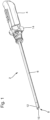
- Fig.1 shows a simplified perspective view of a known endoscope 2 with a proximal handle 4 and a rigid endoscope shaft 6.
- a viewing window 10 is located at a distal tip 8 of the endoscope shaft 6.
- An optical system (not visible) is arranged with which an examination or operation area located in front of the distal tip 8 of the endoscope 2 is imaged on image sensors (also not shown).
- a rotary wheel 14 is connected to the handle 4 in the distal direction, with which the optical system located inside the endoscope shaft 6 can be rotated azimuthally.
- Fig.2 shows in a simplified schematic sectional view a optical system, such as that found in EN 10 2013 215 422 A1 Olympus Winter & Ibe GmbH, Hamburg.
- the optical system comprises a sideways-looking distal optical assembly 16, which is arranged behind the entrance window 10.
- the optical system shown is located in the distal section 12 of the Fig.1 shown stereo video endoscope 2.
- the optical system comprises a proximal optical assembly 18. This can be rotated, for example, by turning the rotary wheel 14 in the endoscope shaft 6.
- the distal optical assembly 16 comprises an entrance lens 20, which is designed, for example, as a raised negative meniscus. It comprises a convex outer surface 22 and a concave inner surface 24.
- the light entering from the left side through the viewing window 10 passes through the entrance lens 20 and falls into a deflection unit 26 designed as a prism unit.
- This comprises two prisms with a partially mirrored or mirrored interface.
- the light incident obliquely from the side is deflected by the deflection unit 26 in the direction of a longitudinal axis of the endoscope shaft 6.
- the deflection unit 26 comprises a first partially mirrored prism 28, which comprises the partially mirrored interface 26b.
- the deflection unit 26 also comprises a further partially mirrored prism 30, which is not shown in detail and comprises the mirrored interface 26a.
- the distal optical assembly 16 comprises an exit lens 32, which is arranged behind a diaphragm 34 in the direction of light incidence.
- a diaphragm 34 in the direction of light incidence.
- rod lenses 40L, 40R of the proximal optical assemblies 18 are arranged for a left lens system channel 38L and a right lens system channel 38R each aperture arranged.
- the light enters the exit lens 32 from the deflection unit 26.
- the exit lens 32 is designed as a hollow positive meniscus lens, for example. It has a concave entrance surface 36a and a convex exit surface 36b.
- the radius of curvature of the concave entrance surface 36a is larger than the radius of curvature of the convex exit surface 36b.
- the light emerging from the exit lens 32 reaches the proximal optical assembly 18.
- This comprises a left lens system channel 38L and a right lens system channel 38R.
- the two lens system channels 38L, 38R are constructed in the same way and are arranged parallel to one another.
- the left optical channel has a left optical axis LoA and the right optical channel has a right optical axis RoA.
- the optical axes LoA, RoA are oriented at least approximately parallel to one another.
- the two lens system channels 38L, 38R each comprise a rod lens 40L, 40R, into which the light first enters from the exit lens 32 of the distal optical assembly 16.
- the left and right rod lenses 40L, 40R are each followed in the direction of light incidence by an achromatic lens group 42L, 42R.
- the achromatic lens groups 42L, 42R are each designed as triplets. The light from these is directed onto the left or right image sensor 44L, 44R, so that the examination or operating area located in front of the distal tip 8 of the endoscope shaft 6 is imaged stereoscopically.
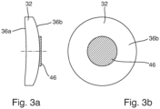
- Fig. 3a and 3b are a cross-sectional view ( Fig. 3a ) and a front view ( Fig. 3b ) of an exit lens 32 of the distal optical unit 16 (cf. Fig.2 ) according to an embodiment of the invention.
- the exit lens 32 is designed as a concave-convex lens with a concave entrance surface 36a and a convex exit surface 36b.
- a circular coating 46 is formed in the middle area on the convex exit surface 36b, so that in the area of the coating 46 no light is allowed through from the coating 46 in the middle area.
- the coating is formed as a circular area on the convex exit surface.
- the coating 46 is formed as a chrome coating.
Landscapes
- Physics & Mathematics (AREA)
- Health & Medical Sciences (AREA)
- Life Sciences & Earth Sciences (AREA)
- Optics & Photonics (AREA)
- Surgery (AREA)
- General Physics & Mathematics (AREA)
- General Health & Medical Sciences (AREA)
- Radiology & Medical Imaging (AREA)
- Astronomy & Astrophysics (AREA)
- Molecular Biology (AREA)
- Medical Informatics (AREA)
- Engineering & Computer Science (AREA)
- Biomedical Technology (AREA)
- Heart & Thoracic Surgery (AREA)
- Nuclear Medicine, Radiotherapy & Molecular Imaging (AREA)
- Animal Behavior & Ethology (AREA)
- Pathology (AREA)
- Biophysics (AREA)
- Public Health (AREA)
- Veterinary Medicine (AREA)
- Instruments For Viewing The Inside Of Hollow Bodies (AREA)
- Endoscopes (AREA)
- Optical Elements Other Than Lenses (AREA)
Description
Die Erfindung betrifft ein optisches System eines Stereo-Videoendoskops mit seitlicher Blickrichtung, umfassend eine seitwärts blickende distale optische Baugruppe und eine proximale optische Baugruppe, wobei die distale optische Baugruppe in einer Lichteinfallsrichtung aufeinanderfolgend eine Eintrittslinse, eine als Prismeneinheit ausgebildete Ablenkeinheit und eine Austrittslinse auf einer gemeinsamen optischen Achse umfasst, und wobei die proximale optische Baugruppe einen linken und einen rechten Linsensystemkanal umfasst, wobei die Linsensystemkanäle gleichartig aufgebaut und parallel zueinander angeordnet sind und jeweils eine eigene optische Achse aufweisen.The invention relates to an optical system of a stereo video endoscope with a lateral viewing direction, comprising a sideways-looking distal optical assembly and a proximal optical assembly, wherein the distal optical assembly comprises, in a light incidence direction, an entrance lens, a deflection unit designed as a prism unit and an exit lens on a common optical axis, and wherein the proximal optical assembly comprises a left and a right lens system channel, wherein the lens system channels are of similar construction and arranged parallel to one another and each have their own optical axis.
Ferner betrifft die Erfindung ein Stereo-Videoendoskop mit seitlicher, insbesondere fester, Blickrichtung sowie eine Verwendung einer Linse für ein optisches System eines Stereo-Videoendoskops. Videoendoskope, bei denen das an einer distalen Spitze eines Endoskopschafts eintretende Licht durch ein optisches System auf einen oder mehrere Bildsensoren gelenkt wird, sind in verschiedenen Ausführungen bekannt. Es gibt Endoskope mit Geradeausblick, einer sog. 0°-Blickrichtung, Endoskope mit (fester) seitlicher Blickrichtung sowie Endoskope mit verstellbarer Blickrichtung (auch als V-DOV-Endoskope bezeichnet).The invention further relates to a stereo video endoscope with a lateral, in particular fixed, viewing direction and to a use of a lens for an optical system of a stereo video endoscope. Video endoscopes in which the lens attached to a distal tip of an endoscope shaft Incoming light is directed by an optical system to one or more image sensors, and is available in various designs. There are endoscopes with a straight-ahead view, a so-called 0° viewing direction, endoscopes with a (fixed) lateral viewing direction and endoscopes with an adjustable viewing direction (also known as V-DOV endoscopes).
Außerdem sind Stereo-Videoendoskope bekannt, die dazu eingerichtet sind, ein stereoskopisches Bildpaar und/oder zwei stereoskopische Videokanäle aufzunehmen. Mit solchen Instrumenten ist es möglich, ein 3D-Abbild eines distal vor dem Ende des Endoskopschafts liegenden Objekts in einem Untersuchungs- oder Operationsraum zu erzeugen.Stereo video endoscopes are also known which are designed to record a stereoscopic image pair and/or two stereoscopic video channels. With such instruments it is possible to create a 3D image of an object located distally in front of the end of the endoscope shaft in an examination or operating room.
Stereo-Videoendoskope mit seitlicher Blickrichtung sind seitwärts blickende Endoskope mit einem festen vom Geradeausblick abweichenden Blickwinkel. Solche Endoskope umfassen vielfach eine Prismenanordnung aus mehreren Prismen, die die aus dem Objektraum unter einem Winkel zur Längsachse des Endoskopschafts in das optische System eintretenden Lichtstrahlen zweimal reflektieren und seitenrichtig in Richtung des Endoskopschafts umlenken. Ein solches Endoskop ist beispielsweise aus der
Eine Umlenkprismenanordnung eines solchen Stereo-Videoendoskops umfasst typischerweise zwei oder drei Prismen. Die Prismen sind an ihren gemeinsamen Grenzflächen vielfach miteinander verkittet. Bei einer solchen Umlenkprismenanordnung findet die Reflektion der einfallenden Lichtbündel an zwei sowohl zur optischen Achse der Eintrittslinse als auch zur Längsachse des Endoskopschafts schrägstehenden reflektierenden Grenzflächen eines zweiten oder dritten Prismas statt. Das zweite oder dritte Prisma der Umlenkprismenanordnung befindet sich in Lichteinfallsrichtung hinter einem ersten oder zweiten Prisma, welches hinter der Eintrittslinse angeordnet ist. Die schrägstehende reflektierende Grenzfläche des zweiten oder dritten Prismas, an der die zweite Reflexion stattfindet, bildet teilweise eine gemeinsame Grenzfläche mit dem vorderen Prisma, welches die einfallenden Lichtstrahlen zuerst durchlaufen.A deflection prism arrangement of such a stereo video endoscope typically comprises two or three prisms. The prisms are often cemented together at their common interfaces. In such a deflection prism arrangement, the reflection of the incident light beams takes place at two reflecting interfaces of a second or third prism that are inclined both to the optical axis of the entrance lens and to the longitudinal axis of the endoscope shaft. The second or third prism of the The deflection prism arrangement is located in the direction of light incidence behind a first or second prism, which is arranged behind the entrance lens. The inclined reflecting interface of the second or third prism, at which the second reflection takes place, partially forms a common interface with the front prism, through which the incident light rays pass first.
Die Eintrittslinse des optischen Systems eines solchen Stereo-Videoendoskops definiert die optische Achse des optischen Systems. Das optische System umfasst Blenden oder Menisken, die ein Blickfeld bzw. die Öffnungswinkel der Optik festlegen. Innerhalb des Blickfeldes in das optische System einfallende Lichtbündel werden von dem optischen System auf einen oder mehrere Bildsensoren abgebildet. Lichtbündel, die von außerhalb des Blickfeldes oder durch Mehrfachreflexionen in das optische System einfallen, erzeugen so sogenannte "Geisterbilder" oder "Flares".The entrance lens of the optical system of such a stereo video endoscope defines the optical axis of the optical system. The optical system comprises apertures or menisci that define a field of view or the opening angle of the optics. Light beams entering the optical system within the field of view are imaged by the optical system onto one or more image sensors. Light beams entering the optical system from outside the field of view or through multiple reflections create so-called "ghost images" or "flares".
Eine bekannte Umlenkprismengruppe, in der solche Geisterbilder entstehen können, umfasst ein erstes Prisma und ein zweites Prisma, die miteinander verkittet sind. Das erste Prisma weist eine Eintrittsseite und eine Austrittsseite auf, wobei die Eintrittsseite gegenüber der Austrittsseite geneigt ist. Die Austrittsseite des ersten Prismas grenzt unmittelbar an eine zweite Eintrittsseite des zweiten Prismas an. Beispielsweise sind das erste und das zweite Prisma an diesen beiden Seiten miteinander verkittet. Das zweite Prisma umfasst ferner eine Reflexionsseite und eine zweite Austrittsseite. Licht, welches aus dem Bildfeld in die Umlenkprismengruppe einfällt, durchquert die Eintrittsseite des ersten Prismas und tritt an dessen Austrittsseite wieder aus. Das Licht gelangt anschließend unmittelbar durch die zweite Eintrittsseite in das zweite Prisma, wird an der Reflexionsseite innerhalb des zweiten Prismas reflektiert und verlässt dieses an der Austrittsseite.A known deflection prism group in which such ghost images can arise comprises a first prism and a second prism which are cemented together. The first prism has an entrance side and an exit side, the entrance side being inclined relative to the exit side. The exit side of the first prism is directly adjacent to a second entrance side of the second prism. For example, the first and second prisms are cemented together on these two sides. The second prism also comprises a reflection side and a second exit side. Light which enters the deflection prism group from the image field passes through the entrance side of the first prism and exits again at its exit side. The light then passes directly through the second entrance side into the second prism, is reflected on the reflection side within the second prism and leaves it at the exit side.
Außerdem offenbart
Darüber hinaus zeigt
Ausgehend von diesem Stand der Technik besteht die Aufgabe der Erfindung darin, bei einem Stereo-Videoendoskop auf einfache Weise die Bildung von Geisterbildern zu verhindern.Based on this prior art, the object of the invention is to prevent the formation of ghost images in a stereo video endoscope in a simple manner.
Gelöst wird diese Aufgabe durch ein optisches System eines Stereo-Videoendoskops mit seitlicher Blickrichtung, umfassend eine seitwärts blickende distale optische Baugruppe und eine proximale optische Baugruppe, wobei die distale optische Baugruppe in einer proximale optische Baugruppe einen linken und einen rechten Linsensystemkanal umfasst, wobei die Linsensystemkanäle gleichartig aufgebaut und parallel zueinander angeordnet sind und jeweils eine eigene optische Achse aufweisen, das dadurch weitergebildet wird, dass die Austrittslinse im mittleren Bereich der Austrittslinse auf ihrer der Ablenkeinheit zugewandten Lichteintrittsseite mit einer lichtundurchlässigen Beschichtung und/oder auf ihrer der Ablenkeinheit abgewandten Lichtaustrittsseite mit einer lichtundurchlässigen Beschichtung ausgebildet ist.This object is achieved by an optical system of a stereo video endoscope with a lateral viewing direction, comprising a sideways-looking distal optical assembly and a proximal optical assembly, wherein the distal optical assembly is arranged in a proximal optical assembly comprises a left and a right lens system channel, wherein the lens system channels are constructed in the same way and arranged parallel to one another and each have their own optical axis, which is further developed in that the exit lens in the middle region of the exit lens is formed with an opaque coating on its light entry side facing the deflection unit and/or with an opaque coating on its light exit side facing away from the deflection unit.
Die Erfindung beruht auf dem Gedanken, dass die Austrittslinse der distalen optischen Baugruppe, die vorzugsweise an der Prismeneinheit der distalen optischen Baugruppe angeordnet ist, mit einer Beschichtung versehen ist, wodurch kein Licht im mittleren Bereich durch die Austrittslinse hindurchtritt und die Bildung von Geisterbildern in den Linsensystemkanälen minimiert oder verhindert wird.The invention is based on the idea that the exit lens of the distal optical assembly, which is preferably arranged on the prism unit of the distal optical assembly, is provided with a coating, whereby no light passes through the exit lens in the central region and the formation of ghost images in the lens system channels is minimized or prevented.
Die Austrittslinse ist vorzugsweise als Prismalinse ausgebildet, wobei die Lichtstrahlen für den linken und rechten optischen Kanal Lichteinfallsrichtung aufeinanderfolgend eine Eintrittslinse, eine als Prismeneinheit ausgebildete Ablenkeinheit und eine Austrittslinse auf einer gemeinsamen optischen Achse umfasst, und wobei die proximale optische Baugruppe einen linken und einen rechten Linsensystemkanal umfasst, wobei die Linsensystemkanäle gleichartig aufgebaut und parallel zueinander angeordnet sind und jeweils eine eigene optische Achse aufweisen, das dadurch weitergebildet wird, dass die Austrittslinse auf ihrer der Ablenkeinheit abgewandten Lichtaustrittsseite mit einer lichtundurchlässigen Beschichtung ausgebildet ist.The exit lens is preferably designed as a prism lens, with the light rays for the left and right optical channels Light incidence direction successively comprises an entrance lens, a deflection unit designed as a prism unit and an exit lens on a common optical axis, and wherein the proximal optical assembly comprises a left and a right lens system channel, wherein the lens system channels are constructed identically and arranged parallel to one another and each have their own optical axis, which is further developed in that the exit lens is formed with an opaque coating on its light exit side facing away from the deflection unit.
Die Erfindung beruht auf dem Gedanken, dass die Austrittslinse der distalen optischen Baugruppe, die vorzugsweise an der Prismeneinheit der distalen optischen Baugruppe angeordnet ist, mit einer Beschichtung versehen ist, wodurch kein Licht im mittleren Bereich durch die Austrittslinse hindurchtritt und die Bildung von Geisterbildern in den Linsensystemkanälen minimiert oder verhindert wird.The invention is based on the idea that the exit lens of the distal optical assembly, which is preferably arranged on the prism unit of the distal optical assembly, is provided with a coating, whereby no light passes through the exit lens in the central region and the formation of ghost images in the lens system channels is minimized or prevented.
Die Austrittslinse ist vorzugsweise als Prismalinse ausgebildet, wobei die Lichtstrahlen für den linken und rechten optischen Kanal zwischen dem Bereich der lichtdurchlässigen Beschichtung auf der Austrittslinse und dem äußeren Rand der Austrittslinse hindurchgelassen werden. Im mittleren Bereich der Austrittslinse, in dem die Beschichtung oder Beschichtungen auf der Austrittslinse aufgetragen sind, werden keine Lichtstrahlen hindurchgelassen. Durch die Beschichtung oder Beschichtungen weist die Austrittslinse einen ringförmigen oder ringartigen optischen Durchlassbereich auf.The exit lens is preferably designed as a prism lens, with the light rays for the left and right optical channels being allowed to pass between the region of the light-transmissive coating on the exit lens and the outer edge of the exit lens. In the central region of the exit lens, in which the coating or coatings are applied to the exit lens, no light rays are allowed to pass. Due to the coating or coatings, the exit lens has an annular or ring-like optical transmission region.
Vorzugsweise ist die Austrittslinse im mittleren Bereich der Austrittslinse auf ihrer der Ablenkeinheit zugewandten Lichteintrittsseite mit einer lichtundurchlässigen Beschichtung ausgebildet.Preferably, the exit lens is formed with an opaque coating in the central region of the exit lens on its light entry side facing the deflection unit.
In einer Weiterbildung des optischen Systems ist vorgesehen, dass die Beschichtung auf der Austrittslinse auf ihrer der Ablenkeinheit abgewandten Lichtaustrittsseite kreisförmig oder kreisartig ausgebildet ist und/oder dass die Beschichtung auf der Austrittslinse auf ihrer der Ablenkeinheit zugewandten Lichtaustrittsseite kreisförmig oder kreisartig ausgebildet ist.In a further development of the optical system, it is provided that the coating on the exit lens is circular or circular-shaped on its light exit side facing away from the deflection unit and/or that the coating on the exit lens is circular or circular-shaped on its light exit side facing the deflection unit.
Vorzugsweise ist die Austrittslinse für den linken Linsensystemkanal und den rechten Linsensystemkanal der proximalen optischen Baugruppe lichtdurchlässig, wobei insbesondere der optische Durchlassbereich der Austrittslinse ringartig oder ringförmig außerhalb der Beschichtung(en) ausgebildet ist.Preferably, the exit lens is transparent to the left lens system channel and the right lens system channel of the proximal optical assembly, wherein in particular the optical transmission region of the exit lens is formed in a ring-like manner or in a ring-shaped manner outside the coating(s).
Ferner ist es bevorzugt, dass die von der Ablenkeinheit abgewandte Seite der Austrittslinse konvex ist.Furthermore, it is preferred that the side of the exit lens facing away from the deflection unit is convex.
Vorzugsweise ist die Austrittslinse als konkav-konvexe Linse ausgebildet.Preferably, the exit lens is designed as a concave-convex lens.
Des Weiteren ist bei dem optischen System bevorzugt, dass die Beschichtung auf der Austrittslinse auf ihrer der Ablenkeinheit abgewandten Lichtaustrittsseite als Antireflexbeschichtung ausgebildet ist und/oder dass die Beschichtung auf der Austrittslinse auf ihrer der Ablenkeinheit zugewandten Lichtaustrittsseite als Antireflexbeschichtung ausgebildet ist. Als Antireflexbeschichtung ist eine Beschichtung vorgesehen, um die Entstehung von Flares oder Geisterbilder zu verringern oder zu vermeiden.Furthermore, in the optical system it is preferred that the coating on the exit lens on its light exit side facing away from the deflection unit is designed as an anti-reflective coating and/or that the coating on the exit lens on its light exit side facing the deflection unit is designed as an anti-reflective coating. A coating is provided as an anti-reflective coating in order to reduce or avoid the formation of flares or ghost images.
Ferner ist es bevorzugt, dass die lichtundurchlässige Beschichtung oder die Antireflexbeschichtung als Chrombeschichtung ausgebildet ist.Furthermore, it is preferred that the opaque coating or the anti-reflective coating is formed as a chrome coating.
Außerdem wird die Aufgabe gelöst durch ein Stereo-Videoendoskop mit fester, vorzugsweise seitlicher, Blickrichtung mit einem optischen System wie voranstehend beschrieben. Hierbei umfasst das optische System eine oder mehrere der zuvor genannten Ausführungsformen.In addition, the object is achieved by a stereo video endoscope with a fixed, preferably lateral, viewing direction with an optical system as described above. The optical system comprises one or more of the previously mentioned embodiments.
Des Weiteren wird die Aufgabe gelöst durch eine Verwendung einer Linse für ein optisches System eines Stereo-Videoendoskops mit fester Blickrichtung, wobei das optische System gemäß der voranstehend genannten Ausführungsformen ausgebildet ist, wobei die Linse als Austrittslinse einer distalen optischen Baugruppe ausgebildet ist und im mittleren Bereich der Austrittslinse auf ihrer einer Ablenkeinheit der distalen optischen Baugruppe abgewandten Lichtaustrittsseite mit einer lichtundurchlässigen Beschichtung ausgebildet ist.Furthermore, the object is achieved by using a lens for an optical system of a stereo video endoscope with a fixed viewing direction, wherein the optical system is designed according to the embodiments mentioned above, wherein the lens is designed as an exit lens of a distal optical assembly and is formed with an opaque coating in the central region of the exit lens on its light exit side facing away from a deflection unit of the distal optical assembly.
Weitere Merkmale der Erfindung werden aus der Beschreibung erfindungsgemäßer Ausführungsformen zusammen mit den Ansprüchen und den beigefügten Zeichnungen ersichtlich. Erfindungsgemäße Ausführungsformen können einzelne Merkmale oder eine Kombination mehrerer Merkmale erfüllen.Further features of the invention will become apparent from the description of embodiments of the invention together with the claims and the accompanying drawings. Embodiments of the invention may fulfill individual features or a combination of several features.
Die Erfindung wird nachstehend ohne Beschränkung des allgemeinen Erfindungsgedankens anhand von Ausführungsbeispielen unter Bezugnahme auf die Zeichnungen beschrieben, wobei bezüglich aller im Text nicht näher erläuterten erfindungsgemäßen Einzelheiten ausdrücklich auf die Zeichnungen verwiesen wird. Es zeigen:
- Fig. 1
- schematisch ein Stereo-Videoendoskop in vereinfachter perspektivischer Darstellung,
- Fig. 2
- ein optisches System eines Stereo-Videoendoskops gemäß dem Stand der Technik in einer vereinfachten schematischen Schnittansicht,
- Fig. 3a
- schematisch einen Querschnitt durch eine erfindungsgemäße Austrittslinse einer distalen optischen Baugruppe des Stereo-Videoendoskops und
- Fig. 3b
- schematisch eine Ansicht der Austrittslinse der distalen optischen Baugruppe.
- Fig.1
- schematically a stereo video endoscope in simplified perspective representation,
- Fig.2
- an optical system of a stereo video endoscope according to the prior art in a simplified schematic sectional view,
- Fig. 3a
- schematically a cross section through an exit lens according to the invention of a distal optical assembly of the stereo video endoscope and
- Fig. 3b
- schematic view of the exit lens of the distal optical assembly.
In den Zeichnungen sind jeweils gleiche oder gleichartige Elemente und/oder Teile mit denselben Bezugsziffern versehen, so dass von einer erneuten Vorstellung jeweils abgesehen wird.In the drawings, identical or similar elements and/or parts are provided with the same reference numbers, so that a repeated presentation is dispensed with in each case.
Die distale optische Baugruppe 16 umfasst eine Eintrittslinse 20, die beispielsweise als erhabener negativer Meniskus ausgebildet ist. Sie umfasst eine konvexe äußere Oberfläche 22 und eine konkave innere Oberfläche 24. Das von der linken Seite her durch das Sichtfenster 10 eintretende Licht durchquert die Eintrittslinse 20 und fällt in eine als Prismeneinheit ausgebildete Ablenkeinheit 26. Diese umfasst zwei Prismen mit einer teilverspiegelten bzw. verspiegelten Grenzfläche. Das schräg von der Seite her einfallende Licht wird durch die Ablenkeinheit 26 in Richtung einer Längsachse des Endoskopschafts 6 umgelenkt. Die Ablenkeinheit 26 umfasst ein erstes teilverspiegeltes Prisma 28, welches die teilverspiegelte Grenzfläche 26b umfasst. Ferner umfasst die Ablenkeinheit 26 ein weiteres teilverspiegeltes Prisma 30, welches nicht näher dargestellt ist und die verspiegelte Grenzfläche 26a umfasst.The distal
Ferner umfasst die distale optische Baugruppe 16 eine Austrittslinse 32, die in Lichteinfallsrichtung hinter einer Blende 34 angeordnet ist. Alternativ ist zwischen der Austrittslinse 32 und der Ablenkeinheit 26 keine Blende vorgesehen. In diesem Fall sind in Lichteinfallsrichtung vor Stablinsen 40L, 40R der proximalen optischen Baugruppen 18 für einen linken Linsensystemkanal 38L und einen rechten Linsensystemkanal 38R jeweils Blenden angeordnet.Furthermore, the distal
In die Austrittslinse 32 tritt das Licht ausgehend von der Ablenkeinheit 26 ein. Die Austrittslinse 32 ist beispielhaft als hohle positive Meniskuslinse ausgebildet. Sie weist eine konkave Eintrittsfläche 36a und eine konvexe Austrittsfläche 36b auf. Dabei ist der Krümmungsradius der konkaven Eintrittsfläche 36a größer als der Krümmungsradius der konvexen Austrittsfläche 36b.The light enters the
Nach einer kurzen Strecke erreicht das aus der Austrittslinse 32 austretende Licht die proximale optische Baugruppe 18. Diese umfasst einen linken Linsensystemkanal 38L und einen rechten Linsensystemkanal 38R. Die beiden Linsensystemkanäle 38L, 38R sind gleichartig aufgebaut und zueinander parallel angeordnet. Der linke optische Kanal weist eine linke optische Achse LoA und der rechte optische Kanal weist eine rechte optische Achse RoA auf. Die optischen Achsen LoA, RoA sind zumindest näherungsweise parallel zueinander orientiert. Die beiden Linsensystemkanäle 38L, 38R umfassen jeweils eine Stablinse 40L, 40R, in die das Licht ausgehend von der Austrittslinse 32 der distalen optischen Baugruppe 16 zuerst eintritt. An die linke und rechte Stablinse 40L, 40R schließt sich in Lichteinfallsrichtung jeweils eine Achromaten-Linsengruppe 42L, 42R an. Die Achromaten-Linsengruppen 42L, 42R sind jeweils als Tripletts ausgebildet. Von diesen wird das Licht auf den linken bzw. rechten Bildsensor 44L, 44R gelenkt, so dass der vor der distalen Spitze 8 des Endoskopschafts 6 liegende Untersuchungs- oder Operationsraum stereoskopisch abgebildet wird.After a short distance, the light emerging from the
Weitere Einzelheiten zum Aufbau des in
In den
Erfindungsgemäß ist im mittleren Bereich auf der konvexen Austrittsfläche 36b eine kreisförmige Beschichtung 46 ausgebildet, so dass im Bereich der Beschichtung 46 kein Licht von der Beschichtung 46 im mittleren Bereich hindurchgelassen wird. Insbesondere ist die Beschichtung als kreisförmige Fläche auf der konvexen Austrittsfläche ausgebildet. Vorzugsweise ist dabei die Beschichtung 46 als Chrombeschichtung ausgebildet.According to the invention, a
Alle genannten Merkmale, auch die den Zeichnungen allein zu entnehmenden sowie auch einzelne Merkmale, die in Kombination mit anderen Merkmalen offenbart sind, werden allein und in Kombination als erfindungswesentlich angesehen. Erfindungsgemäße Ausführungsformen können durch einzelne Merkmale oder eine Kombination mehrerer Merkmale erfüllt sein. Im Rahmen der Erfindung sind Merkmale, die mit "insbesondere" oder "vorzugsweise" gekennzeichnet sind, als fakultative Merkmale zu verstehen.All of the features mentioned, including those that can be taken from the drawings alone and also individual features that are disclosed in combination with other features, are considered essential to the invention alone and in combination. Embodiments according to the invention can be fulfilled by individual features or a combination of several features. Within the scope of the invention, features that are marked with "in particular" or "preferably" are to be understood as optional features.
- 22
- Stereo-VideoendoskopStereo video endoscope
- 44
- HandgriffHandle
- 66
- EndoskopschaftEndoscope shaft
- 88th
- distale Spitzedistal tip
- 1010
- SichtfensterViewing window
- 1212
- distaler Abschnittdistal section
- 1414
- DrehradRotary wheel
- 1616
- distale optische Baugruppedistal optical assembly
- 1818
- proximale optische Baugruppeproximal optical assembly
- 2020
- EintrittslinseEntrance lens
- 2222
- äußere Oberflächeouter surface
- 2424
- innere Oberflächeinner surface
- 2626
- AblenkeinheitDeflection unit
- 26a, 26b26a, 26b
- GrenzflächeInterface
- 2828
- teilverspiegeltes Prismapartially mirrored prism
- 3030
- weiteres teilverspiegeltes Prismaanother partially mirrored prism
- 3232
- AustrittslinseExit lens
- 3434
- Blendecover
- 36a36a
- konkave Eintrittsflächeconcave entrance surface
- 36b36b
- konvexe Austrittsflächeconvex exit surface
- 38L38L
- linker Linsensystemkanalleft lens system channel
- 38R38R
- rechter Linsensystemkanalright lens system channel
- 40L, 40R40L, 40R
- StablinseRod lens
- 42L, 42R42L, 42R
- Achromaten-LinsengruppeAchromatic lens group
- 44L, 44R44L, 44R
- BildsensorImage sensor
- 4646
- BeschichtungCoating
- LoALoA
- linke optische Achseleft optical axis
- RoARoA
- rechte optische Achseright optical axis
Claims (10)
- An optical system of a stereo-video endoscope (2) with a sideways viewing direction, comprising a sideways-viewing distal optical assembly (16) and a proximal optical assembly (18), wherein the distal optical assembly (16) comprises an inlet lens (20), a deflecting unit (26) designed as a prism unit, and an outlet lens (32) on a common optical axis one after the other in the direction of light incidence, and the proximal optical assembly (18) comprises a left and a right lens system channel (38L, 38R), wherein the lens system channels (38L, 38R) are identically designed and are arranged parallel to each other, and each lens system channel has its own optical axis (LoA, RoA), characterized in that the outlet lens (32) is formed with a light-impermeable coating (46) on the light outlet side (36b) facing away from the deflecting unit (26) in the central region of the outlet lens (32).
- The optical system according to claim 1, characterized in that characterized in that the outlet lens (32) is formed with a light-impermeable coating (46) on the light inlet side (36a) facing the deflecting unit (26) in the central region of the outlet lens (32).
- The optical system according to claim 1 or 2, characterized in that the coating (46) on the outlet lens is formed in the form of a circle or in the manner of a circle on the light outlet side (36b) facing away from the deflecting unit (26) and/or the coating (46) on the outlet lens is formed in the form of a circle or in the manner of a circle on the light inlet side (36a) facing the deflecting unit (26).
- The optical system according to any one of claims 1 to 3, characterized in that the outlet lens (32) for the left lens system channel (38L) and the right lens system channel (38R) of the proximal optical assembly (18) is permeable to light.
- The optical system according to any one of claims 1 to 4, characterized in that the side of the outlet lens (32) facing away from the deflecting unit (26) is convex.
- The optical system according to any one of claims 1 to 5, characterized in that the outlet lens (32) is formed as a concaveconvex lens.
- The optical system according to any one of claims 1 to 6, characterized in that the coating (46) on the outlet lens (32) is formed as an anti-reflex coating (46) on the light outlet side (36b) facing away from the deflecting unit (26) and/or that the coating (46) on the outlet lens (32) is formed as an anti-reflex coating (46) on the light inlet side (36a) facing the deflecting unit (26).
- The optical system according to claim 7, characterized in that the anti-reflex coating (46) is formed as a chromium coating (46).
- A stereo-video endoscope (2) having a fixed viewing direction having an optical system (20) according to any one of claims 1 to 8.
- Use of a lens (32) for an optical system (20) of a stereo-video endoscope (2) having a fixed viewing direction according to any one of claims 1 to 8, wherein the lens (32) is formed as an outlet lens (32) of a distal optical assembly (16) and is formed with a light-impermeable coating (46) on the light outlet side (36b) facing away from a deflecting unit (26) of the distal optical assembly (16) in the central region of the outlet lens (32).
Priority Applications (1)
| Application Number | Priority Date | Filing Date | Title |
|---|---|---|---|
| EP24176244.2A EP4394481B1 (en) | 2018-02-01 | 2019-01-24 | Optical system of a stereo video endoscope |
Applications Claiming Priority (2)
| Application Number | Priority Date | Filing Date | Title |
|---|---|---|---|
| DE102018102268.9A DE102018102268A1 (en) | 2018-02-01 | 2018-02-01 | Optical system of a stereo video endoscope |
| PCT/EP2019/051700 WO2019149609A1 (en) | 2018-02-01 | 2019-01-24 | Optical system of a stereo-video endoscope |
Related Child Applications (2)
| Application Number | Title | Priority Date | Filing Date |
|---|---|---|---|
| EP24176244.2A Division EP4394481B1 (en) | 2018-02-01 | 2019-01-24 | Optical system of a stereo video endoscope |
| EP24176244.2A Division-Into EP4394481B1 (en) | 2018-02-01 | 2019-01-24 | Optical system of a stereo video endoscope |
Publications (2)
| Publication Number | Publication Date |
|---|---|
| EP3746830A1 EP3746830A1 (en) | 2020-12-09 |
| EP3746830B1 true EP3746830B1 (en) | 2024-07-31 |
Family
ID=65243533
Family Applications (2)
| Application Number | Title | Priority Date | Filing Date |
|---|---|---|---|
| EP19702368.2A Active EP3746830B1 (en) | 2018-02-01 | 2019-01-24 | Optical system of a stereo-video endoscope |
| EP24176244.2A Active EP4394481B1 (en) | 2018-02-01 | 2019-01-24 | Optical system of a stereo video endoscope |
Family Applications After (1)
| Application Number | Title | Priority Date | Filing Date |
|---|---|---|---|
| EP24176244.2A Active EP4394481B1 (en) | 2018-02-01 | 2019-01-24 | Optical system of a stereo video endoscope |
Country Status (5)
| Country | Link |
|---|---|
| US (1) | US11391939B2 (en) |
| EP (2) | EP3746830B1 (en) |
| JP (1) | JP7023374B2 (en) |
| DE (1) | DE102018102268A1 (en) |
| WO (1) | WO2019149609A1 (en) |
Families Citing this family (1)
| Publication number | Priority date | Publication date | Assignee | Title |
|---|---|---|---|---|
| DE102016214272A1 (en) * | 2016-08-02 | 2018-02-22 | Olympus Winter & Ibe Gmbh | Optical system of a stereo video endoscope with side view and method of making the same |
Citations (1)
| Publication number | Priority date | Publication date | Assignee | Title |
|---|---|---|---|---|
| US20170235121A1 (en) * | 2015-05-28 | 2017-08-17 | Olympus Corporation | Endoscope objective optical system |
Family Cites Families (14)
| Publication number | Priority date | Publication date | Assignee | Title |
|---|---|---|---|---|
| JPH04138402A (en) * | 1990-09-28 | 1992-05-12 | Minolta Camera Co Ltd | Photographic lens |
| US5341240A (en) * | 1992-02-06 | 1994-08-23 | Linvatec Corporation | Disposable endoscope |
| JP3580869B2 (en) * | 1994-09-13 | 2004-10-27 | オリンパス株式会社 | Stereoscopic endoscope |
| US6682478B2 (en) * | 2001-02-08 | 2004-01-27 | Olympus Optical Co., Ltd. | Endoscope apparatus with an insertion part having a small outer diameter which includes and object optical system |
| EP1542053B1 (en) * | 2003-12-11 | 2007-11-14 | Tokendo | Measuring device for video-endoscopic probe |
| JP2005223716A (en) | 2004-02-06 | 2005-08-18 | Rohm Co Ltd | Image sensor module and lens unit therefor |
| JP2009288682A (en) * | 2008-05-30 | 2009-12-10 | Olympus Medical Systems Corp | Objective optical system for endoscopes |
| DE102013215422B4 (en) | 2013-08-06 | 2022-02-24 | Olympus Winter & Ibe Gmbh | Optical system of a stereo video endoscope with side view and stereo video endoscope with side view |
| JP6035450B2 (en) * | 2014-03-03 | 2016-11-30 | 富士フイルム株式会社 | Optical element manufacturing method |
| DE102014206513A1 (en) | 2014-04-04 | 2015-10-08 | Olympus Winter & Ibe Gmbh | Stereoscopic endoscope system and endoscope, assembly procedure |
| IL236418A (en) | 2014-12-23 | 2016-07-31 | Visionsense Ltd | Rotatable oblique viewing stereoendoscope |
| DE112016000121B4 (en) * | 2015-09-07 | 2019-07-04 | Hoya Corporation | Endoscope magnifying optics and endoscope |
| WO2017104427A1 (en) * | 2015-12-17 | 2017-06-22 | オリンパス株式会社 | Optical adapter for endoscope |
| DE102016122429A1 (en) | 2016-11-22 | 2018-05-24 | Karl Storz Se & Co. Kg | Negative lens and endoscope lens |
-
2018
- 2018-02-01 DE DE102018102268.9A patent/DE102018102268A1/en active Pending
-
2019
- 2019-01-24 EP EP19702368.2A patent/EP3746830B1/en active Active
- 2019-01-24 EP EP24176244.2A patent/EP4394481B1/en active Active
- 2019-01-24 JP JP2020542096A patent/JP7023374B2/en active Active
- 2019-01-24 WO PCT/EP2019/051700 patent/WO2019149609A1/en not_active Ceased
-
2020
- 2020-07-30 US US16/943,461 patent/US11391939B2/en active Active
Patent Citations (1)
| Publication number | Priority date | Publication date | Assignee | Title |
|---|---|---|---|---|
| US20170235121A1 (en) * | 2015-05-28 | 2017-08-17 | Olympus Corporation | Endoscope objective optical system |
Also Published As
| Publication number | Publication date |
|---|---|
| DE102018102268A1 (en) | 2019-08-01 |
| EP4394481A2 (en) | 2024-07-03 |
| EP4394481B1 (en) | 2026-05-27 |
| EP3746830A1 (en) | 2020-12-09 |
| US11391939B2 (en) | 2022-07-19 |
| WO2019149609A1 (en) | 2019-08-08 |
| JP7023374B2 (en) | 2022-02-21 |
| US20200355909A1 (en) | 2020-11-12 |
| JP2021512372A (en) | 2021-05-13 |
| EP4394481A3 (en) | 2024-09-04 |
Similar Documents
| Publication | Publication Date | Title |
|---|---|---|
| DE102013215422B4 (en) | Optical system of a stereo video endoscope with side view and stereo video endoscope with side view | |
| EP1862837B1 (en) | Multi-spectral optical imaging system | |
| EP2647330B1 (en) | Protective shell for an endoscope with an endoscope tube | |
| DE2638999C3 (en) | Lens for vision devices with fiber optics | |
| DE102016219217B4 (en) | Angle-selective optical system, stereo video endoscope with such a system and method for producing the same | |
| DE3447893C2 (en) | ||
| WO2015055282A1 (en) | Endoscope having an adjustable viewing direction | |
| EP3494431B1 (en) | Optical system of a stereo-video endoscope having a lateral viewing direction, and method for producing same | |
| EP3276390B1 (en) | Optical system and surgical instrument with such an optical system | |
| EP1000374A2 (en) | Endoscopic lens | |
| DE102022124306A1 (en) | Visualization system with optimized deflection prism | |
| WO2015150078A1 (en) | Stereoscopic endoscope system and endoscope, assembly method | |
| EP3694388B1 (en) | Optical system for a stereo-video endoscope | |
| EP3555686B1 (en) | Optical system for a side-viewing endoscope, and side-viewing endoscope | |
| WO2019175044A1 (en) | Optical system of a stereo video endoscope and method for producing same | |
| EP3749999B1 (en) | Optical system of an endoscope, endoscope, stereo-video endoscope, and method for producing an optical system | |
| EP4394481A2 (en) | Optical system of a stereo video endoscope | |
| DE102018116139B4 (en) | Optical system and stereo video endoscope | |
| DE102014211367A1 (en) | Prism device and endoscope | |
| EP1088251A1 (en) | Optical adapter system for a camera | |
| DE102019100809A1 (en) | Optical system of an endoscope and endoscope | |
| DE2430148C3 (en) | Endoscope with a viewing direction that can be changed between straight vision and side vision, in which a fiber bundle is used to transmit the image that is focused on its end by means of an objective | |
| DE102017131131A1 (en) | Optical system of a stereo video endoscope with aperture | |
| WO2017012854A1 (en) | Prism arrangement for an endoscope with a lateral viewing direction, and endoscope |
Legal Events
| Date | Code | Title | Description |
|---|---|---|---|
| STAA | Information on the status of an ep patent application or granted ep patent |
Free format text: STATUS: UNKNOWN |
|
| STAA | Information on the status of an ep patent application or granted ep patent |
Free format text: STATUS: THE INTERNATIONAL PUBLICATION HAS BEEN MADE |
|
| PUAI | Public reference made under article 153(3) epc to a published international application that has entered the european phase |
Free format text: ORIGINAL CODE: 0009012 |
|
| STAA | Information on the status of an ep patent application or granted ep patent |
Free format text: STATUS: REQUEST FOR EXAMINATION WAS MADE |
|
| 17P | Request for examination filed |
Effective date: 20200720 |
|
| AK | Designated contracting states |
Kind code of ref document: A1 Designated state(s): AL AT BE BG CH CY CZ DE DK EE ES FI FR GB GR HR HU IE IS IT LI LT LU LV MC MK MT NL NO PL PT RO RS SE SI SK SM TR |
|
| AX | Request for extension of the european patent |
Extension state: BA ME |
|
| DAV | Request for validation of the european patent (deleted) | ||
| DAX | Request for extension of the european patent (deleted) | ||
| STAA | Information on the status of an ep patent application or granted ep patent |
Free format text: STATUS: EXAMINATION IS IN PROGRESS |
|
| 17Q | First examination report despatched |
Effective date: 20220627 |
|
| P01 | Opt-out of the competence of the unified patent court (upc) registered |
Effective date: 20230524 |
|
| GRAP | Despatch of communication of intention to grant a patent |
Free format text: ORIGINAL CODE: EPIDOSNIGR1 |
|
| STAA | Information on the status of an ep patent application or granted ep patent |
Free format text: STATUS: GRANT OF PATENT IS INTENDED |
|
| INTG | Intention to grant announced |
Effective date: 20240326 |
|
| GRAS | Grant fee paid |
Free format text: ORIGINAL CODE: EPIDOSNIGR3 |
|
| GRAA | (expected) grant |
Free format text: ORIGINAL CODE: 0009210 |
|
| STAA | Information on the status of an ep patent application or granted ep patent |
Free format text: STATUS: THE PATENT HAS BEEN GRANTED |
|
| AK | Designated contracting states |
Kind code of ref document: B1 Designated state(s): AL AT BE BG CH CY CZ DE DK EE ES FI FR GB GR HR HU IE IS IT LI LT LU LV MC MK MT NL NO PL PT RO RS SE SI SK SM TR |
|
| REG | Reference to a national code |
Ref country code: CH Ref legal event code: EP Ref country code: GB Ref legal event code: FG4D Free format text: NOT ENGLISH |
|
| REG | Reference to a national code |
Ref country code: DE Ref legal event code: R096 Ref document number: 502019011780 Country of ref document: DE |
|
| REG | Reference to a national code |
Ref country code: IE Ref legal event code: FG4D Free format text: LANGUAGE OF EP DOCUMENT: GERMAN |
|
| REG | Reference to a national code |
Ref country code: LT Ref legal event code: MG9D |
|
| REG | Reference to a national code |
Ref country code: NL Ref legal event code: MP Effective date: 20240731 |
|
| PG25 | Lapsed in a contracting state [announced via postgrant information from national office to epo] |
Ref country code: PT Free format text: LAPSE BECAUSE OF FAILURE TO SUBMIT A TRANSLATION OF THE DESCRIPTION OR TO PAY THE FEE WITHIN THE PRESCRIBED TIME-LIMIT Effective date: 20241202 |
|
| PG25 | Lapsed in a contracting state [announced via postgrant information from national office to epo] |
Ref country code: PT Free format text: LAPSE BECAUSE OF FAILURE TO SUBMIT A TRANSLATION OF THE DESCRIPTION OR TO PAY THE FEE WITHIN THE PRESCRIBED TIME-LIMIT Effective date: 20241202 |
|
| PG25 | Lapsed in a contracting state [announced via postgrant information from national office to epo] |
Ref country code: NO Free format text: LAPSE BECAUSE OF FAILURE TO SUBMIT A TRANSLATION OF THE DESCRIPTION OR TO PAY THE FEE WITHIN THE PRESCRIBED TIME-LIMIT Effective date: 20241031 |
|
| PG25 | Lapsed in a contracting state [announced via postgrant information from national office to epo] |
Ref country code: NL Free format text: LAPSE BECAUSE OF FAILURE TO SUBMIT A TRANSLATION OF THE DESCRIPTION OR TO PAY THE FEE WITHIN THE PRESCRIBED TIME-LIMIT Effective date: 20240731 Ref country code: FI Free format text: LAPSE BECAUSE OF FAILURE TO SUBMIT A TRANSLATION OF THE DESCRIPTION OR TO PAY THE FEE WITHIN THE PRESCRIBED TIME-LIMIT Effective date: 20240731 Ref country code: GR Free format text: LAPSE BECAUSE OF FAILURE TO SUBMIT A TRANSLATION OF THE DESCRIPTION OR TO PAY THE FEE WITHIN THE PRESCRIBED TIME-LIMIT Effective date: 20241101 Ref country code: PL Free format text: LAPSE BECAUSE OF FAILURE TO SUBMIT A TRANSLATION OF THE DESCRIPTION OR TO PAY THE FEE WITHIN THE PRESCRIBED TIME-LIMIT Effective date: 20240731 |
|
| PG25 | Lapsed in a contracting state [announced via postgrant information from national office to epo] |
Ref country code: BG Free format text: LAPSE BECAUSE OF FAILURE TO SUBMIT A TRANSLATION OF THE DESCRIPTION OR TO PAY THE FEE WITHIN THE PRESCRIBED TIME-LIMIT Effective date: 20240731 |
|
| PG25 | Lapsed in a contracting state [announced via postgrant information from national office to epo] |
Ref country code: LV Free format text: LAPSE BECAUSE OF FAILURE TO SUBMIT A TRANSLATION OF THE DESCRIPTION OR TO PAY THE FEE WITHIN THE PRESCRIBED TIME-LIMIT Effective date: 20240731 |
|
| PG25 | Lapsed in a contracting state [announced via postgrant information from national office to epo] |
Ref country code: IS Free format text: LAPSE BECAUSE OF FAILURE TO SUBMIT A TRANSLATION OF THE DESCRIPTION OR TO PAY THE FEE WITHIN THE PRESCRIBED TIME-LIMIT Effective date: 20241130 |
|
| PG25 | Lapsed in a contracting state [announced via postgrant information from national office to epo] |
Ref country code: HR Free format text: LAPSE BECAUSE OF FAILURE TO SUBMIT A TRANSLATION OF THE DESCRIPTION OR TO PAY THE FEE WITHIN THE PRESCRIBED TIME-LIMIT Effective date: 20240731 |
|
| PG25 | Lapsed in a contracting state [announced via postgrant information from national office to epo] |
Ref country code: RS Free format text: LAPSE BECAUSE OF FAILURE TO SUBMIT A TRANSLATION OF THE DESCRIPTION OR TO PAY THE FEE WITHIN THE PRESCRIBED TIME-LIMIT Effective date: 20241031 Ref country code: ES Free format text: LAPSE BECAUSE OF FAILURE TO SUBMIT A TRANSLATION OF THE DESCRIPTION OR TO PAY THE FEE WITHIN THE PRESCRIBED TIME-LIMIT Effective date: 20240731 |
|
| PG25 | Lapsed in a contracting state [announced via postgrant information from national office to epo] |
Ref country code: RS Free format text: LAPSE BECAUSE OF FAILURE TO SUBMIT A TRANSLATION OF THE DESCRIPTION OR TO PAY THE FEE WITHIN THE PRESCRIBED TIME-LIMIT Effective date: 20241031 Ref country code: PL Free format text: LAPSE BECAUSE OF FAILURE TO SUBMIT A TRANSLATION OF THE DESCRIPTION OR TO PAY THE FEE WITHIN THE PRESCRIBED TIME-LIMIT Effective date: 20240731 Ref country code: NO Free format text: LAPSE BECAUSE OF FAILURE TO SUBMIT A TRANSLATION OF THE DESCRIPTION OR TO PAY THE FEE WITHIN THE PRESCRIBED TIME-LIMIT Effective date: 20241031 Ref country code: NL Free format text: LAPSE BECAUSE OF FAILURE TO SUBMIT A TRANSLATION OF THE DESCRIPTION OR TO PAY THE FEE WITHIN THE PRESCRIBED TIME-LIMIT Effective date: 20240731 Ref country code: LV Free format text: LAPSE BECAUSE OF FAILURE TO SUBMIT A TRANSLATION OF THE DESCRIPTION OR TO PAY THE FEE WITHIN THE PRESCRIBED TIME-LIMIT Effective date: 20240731 Ref country code: IS Free format text: LAPSE BECAUSE OF FAILURE TO SUBMIT A TRANSLATION OF THE DESCRIPTION OR TO PAY THE FEE WITHIN THE PRESCRIBED TIME-LIMIT Effective date: 20241130 Ref country code: HR Free format text: LAPSE BECAUSE OF FAILURE TO SUBMIT A TRANSLATION OF THE DESCRIPTION OR TO PAY THE FEE WITHIN THE PRESCRIBED TIME-LIMIT Effective date: 20240731 Ref country code: GR Free format text: LAPSE BECAUSE OF FAILURE TO SUBMIT A TRANSLATION OF THE DESCRIPTION OR TO PAY THE FEE WITHIN THE PRESCRIBED TIME-LIMIT Effective date: 20241101 Ref country code: FI Free format text: LAPSE BECAUSE OF FAILURE TO SUBMIT A TRANSLATION OF THE DESCRIPTION OR TO PAY THE FEE WITHIN THE PRESCRIBED TIME-LIMIT Effective date: 20240731 Ref country code: ES Free format text: LAPSE BECAUSE OF FAILURE TO SUBMIT A TRANSLATION OF THE DESCRIPTION OR TO PAY THE FEE WITHIN THE PRESCRIBED TIME-LIMIT Effective date: 20240731 Ref country code: BG Free format text: LAPSE BECAUSE OF FAILURE TO SUBMIT A TRANSLATION OF THE DESCRIPTION OR TO PAY THE FEE WITHIN THE PRESCRIBED TIME-LIMIT Effective date: 20240731 |
|
| PG25 | Lapsed in a contracting state [announced via postgrant information from national office to epo] |
Ref country code: DK Free format text: LAPSE BECAUSE OF FAILURE TO SUBMIT A TRANSLATION OF THE DESCRIPTION OR TO PAY THE FEE WITHIN THE PRESCRIBED TIME-LIMIT Effective date: 20240731 Ref country code: RO Free format text: LAPSE BECAUSE OF FAILURE TO SUBMIT A TRANSLATION OF THE DESCRIPTION OR TO PAY THE FEE WITHIN THE PRESCRIBED TIME-LIMIT Effective date: 20240731 Ref country code: SM Free format text: LAPSE BECAUSE OF FAILURE TO SUBMIT A TRANSLATION OF THE DESCRIPTION OR TO PAY THE FEE WITHIN THE PRESCRIBED TIME-LIMIT Effective date: 20240731 |
|
| PG25 | Lapsed in a contracting state [announced via postgrant information from national office to epo] |
Ref country code: EE Free format text: LAPSE BECAUSE OF FAILURE TO SUBMIT A TRANSLATION OF THE DESCRIPTION OR TO PAY THE FEE WITHIN THE PRESCRIBED TIME-LIMIT Effective date: 20240731 |
|
| PG25 | Lapsed in a contracting state [announced via postgrant information from national office to epo] |
Ref country code: CZ Free format text: LAPSE BECAUSE OF FAILURE TO SUBMIT A TRANSLATION OF THE DESCRIPTION OR TO PAY THE FEE WITHIN THE PRESCRIBED TIME-LIMIT Effective date: 20240731 |
|
| PG25 | Lapsed in a contracting state [announced via postgrant information from national office to epo] |
Ref country code: SK Free format text: LAPSE BECAUSE OF FAILURE TO SUBMIT A TRANSLATION OF THE DESCRIPTION OR TO PAY THE FEE WITHIN THE PRESCRIBED TIME-LIMIT Effective date: 20240731 Ref country code: IT Free format text: LAPSE BECAUSE OF FAILURE TO SUBMIT A TRANSLATION OF THE DESCRIPTION OR TO PAY THE FEE WITHIN THE PRESCRIBED TIME-LIMIT Effective date: 20240731 |
|
| REG | Reference to a national code |
Ref country code: DE Ref legal event code: R097 Ref document number: 502019011780 Country of ref document: DE |
|
| PLBE | No opposition filed within time limit |
Free format text: ORIGINAL CODE: 0009261 |
|
| STAA | Information on the status of an ep patent application or granted ep patent |
Free format text: STATUS: NO OPPOSITION FILED WITHIN TIME LIMIT |
|
| 26N | No opposition filed |
Effective date: 20250501 |
|
| REG | Reference to a national code |
Ref country code: CH Ref legal event code: PL |
|
| PG25 | Lapsed in a contracting state [announced via postgrant information from national office to epo] |
Ref country code: SE Free format text: LAPSE BECAUSE OF FAILURE TO SUBMIT A TRANSLATION OF THE DESCRIPTION OR TO PAY THE FEE WITHIN THE PRESCRIBED TIME-LIMIT Effective date: 20240731 |
|
| PG25 | Lapsed in a contracting state [announced via postgrant information from national office to epo] |
Ref country code: MC Free format text: LAPSE BECAUSE OF FAILURE TO SUBMIT A TRANSLATION OF THE DESCRIPTION OR TO PAY THE FEE WITHIN THE PRESCRIBED TIME-LIMIT Effective date: 20240731 Ref country code: LU Free format text: LAPSE BECAUSE OF NON-PAYMENT OF DUE FEES Effective date: 20250124 |
|
| GBPC | Gb: european patent ceased through non-payment of renewal fee |
Effective date: 20250124 |
|
| PG25 | Lapsed in a contracting state [announced via postgrant information from national office to epo] |
Ref country code: GB Free format text: LAPSE BECAUSE OF NON-PAYMENT OF DUE FEES Effective date: 20250124 Ref country code: BE Free format text: LAPSE BECAUSE OF NON-PAYMENT OF DUE FEES Effective date: 20250131 |
|
| PG25 | Lapsed in a contracting state [announced via postgrant information from national office to epo] |
Ref country code: FR Free format text: LAPSE BECAUSE OF NON-PAYMENT OF DUE FEES Effective date: 20250131 |
|
| PG25 | Lapsed in a contracting state [announced via postgrant information from national office to epo] |
Ref country code: CH Free format text: LAPSE BECAUSE OF NON-PAYMENT OF DUE FEES Effective date: 20250131 |
|
| REG | Reference to a national code |
Ref country code: BE Ref legal event code: MM Effective date: 20250131 |
|
| PG25 | Lapsed in a contracting state [announced via postgrant information from national office to epo] |
Ref country code: IE Free format text: LAPSE BECAUSE OF NON-PAYMENT OF DUE FEES Effective date: 20250124 |
|
| REG | Reference to a national code |
Ref country code: AT Ref legal event code: MM01 Ref document number: 1709024 Country of ref document: AT Kind code of ref document: T Effective date: 20250124 |
|
| PGFP | Annual fee paid to national office [announced via postgrant information from national office to epo] |
Ref country code: DE Payment date: 20251203 Year of fee payment: 8 |
|
| PG25 | Lapsed in a contracting state [announced via postgrant information from national office to epo] |
Ref country code: AT Free format text: LAPSE BECAUSE OF NON-PAYMENT OF DUE FEES Effective date: 20250124 |
|
| PG25 | Lapsed in a contracting state [announced via postgrant information from national office to epo] |
Ref country code: CY Free format text: LAPSE BECAUSE OF FAILURE TO SUBMIT A TRANSLATION OF THE DESCRIPTION OR TO PAY THE FEE WITHIN THE PRESCRIBED TIME-LIMIT Effective date: 20240731 |
|
| PG25 | Lapsed in a contracting state [announced via postgrant information from national office to epo] |
Ref country code: TR Free format text: LAPSE BECAUSE OF FAILURE TO SUBMIT A TRANSLATION OF THE DESCRIPTION OR TO PAY THE FEE WITHIN THE PRESCRIBED TIME-LIMIT Effective date: 20240731 |
|
| PG25 | Lapsed in a contracting state [announced via postgrant information from national office to epo] |
Ref country code: LT Free format text: LAPSE BECAUSE OF FAILURE TO SUBMIT A TRANSLATION OF THE DESCRIPTION OR TO PAY THE FEE WITHIN THE PRESCRIBED TIME-LIMIT Effective date: 20240731 |