EP3747111B1 - Support de tete d'enroulement d'un stator de generateur - Google Patents
Support de tete d'enroulement d'un stator de generateur Download PDFInfo
- Publication number
- EP3747111B1 EP3747111B1 EP18718046.8A EP18718046A EP3747111B1 EP 3747111 B1 EP3747111 B1 EP 3747111B1 EP 18718046 A EP18718046 A EP 18718046A EP 3747111 B1 EP3747111 B1 EP 3747111B1
- Authority
- EP
- European Patent Office
- Prior art keywords
- brace
- bracket
- end winding
- plate
- elastic layer
- Prior art date
- Legal status (The legal status is an assumption and is not a legal conclusion. Google has not performed a legal analysis and makes no representation as to the accuracy of the status listed.)
- Active
Links
Images
Classifications
-
- H—ELECTRICITY
- H02—GENERATION; CONVERSION OR DISTRIBUTION OF ELECTRIC POWER
- H02K—DYNAMO-ELECTRIC MACHINES
- H02K1/00—Details of the magnetic circuit
- H02K1/06—Details of the magnetic circuit characterised by the shape, form or construction
- H02K1/12—Stationary parts of the magnetic circuit
- H02K1/18—Means for mounting or fastening magnetic stationary parts on to, or to, the stator structures
- H02K1/185—Means for mounting or fastening magnetic stationary parts on to, or to, the stator structures to outer stators
-
- H—ELECTRICITY
- H02—GENERATION; CONVERSION OR DISTRIBUTION OF ELECTRIC POWER
- H02K—DYNAMO-ELECTRIC MACHINES
- H02K1/00—Details of the magnetic circuit
- H02K1/06—Details of the magnetic circuit characterised by the shape, form or construction
- H02K1/12—Stationary parts of the magnetic circuit
- H02K1/16—Stator cores with slots for windings
-
- H—ELECTRICITY
- H02—GENERATION; CONVERSION OR DISTRIBUTION OF ELECTRIC POWER
- H02K—DYNAMO-ELECTRIC MACHINES
- H02K3/00—Details of windings
- H02K3/46—Fastening of windings on the stator or rotor structure
- H02K3/50—Fastening of winding heads, equalising connectors, or connections thereto
- H02K3/505—Fastening of winding heads, equalising connectors, or connections thereto for large machine windings, e.g. bar windings
-
- H—ELECTRICITY
- H02—GENERATION; CONVERSION OR DISTRIBUTION OF ELECTRIC POWER
- H02K—DYNAMO-ELECTRIC MACHINES
- H02K3/00—Details of windings
- H02K3/46—Fastening of windings on the stator or rotor structure
- H02K3/50—Fastening of winding heads, equalising connectors, or connections thereto
- H02K3/51—Fastening of winding heads, equalising connectors, or connections thereto applicable to rotors only
-
- H—ELECTRICITY
- H02—GENERATION; CONVERSION OR DISTRIBUTION OF ELECTRIC POWER
- H02K—DYNAMO-ELECTRIC MACHINES
- H02K3/00—Details of windings
- H02K3/46—Fastening of windings on the stator or rotor structure
- H02K3/52—Fastening salient pole windings or connections thereto
-
- H—ELECTRICITY
- H02—GENERATION; CONVERSION OR DISTRIBUTION OF ELECTRIC POWER
- H02K—DYNAMO-ELECTRIC MACHINES
- H02K3/00—Details of windings
- H02K3/46—Fastening of windings on the stator or rotor structure
- H02K3/52—Fastening salient pole windings or connections thereto
- H02K3/521—Fastening salient pole windings or connections thereto applicable to stators only
- H02K3/522—Fastening salient pole windings or connections thereto applicable to stators only for generally annular cores with salient poles
-
- H—ELECTRICITY
- H02—GENERATION; CONVERSION OR DISTRIBUTION OF ELECTRIC POWER
- H02K—DYNAMO-ELECTRIC MACHINES
- H02K3/00—Details of windings
- H02K3/46—Fastening of windings on the stator or rotor structure
- H02K3/52—Fastening salient pole windings or connections thereto
- H02K3/521—Fastening salient pole windings or connections thereto applicable to stators only
- H02K3/525—Annular coils, e.g. for cores of the claw-pole type
Definitions
- the present invention relates generally to a generator stator of an electric machine, and more in particular, a generator stator end winding coil support assembly for a large turbine generator.
- Generator is a component that converts mechanical power to electrical power in power generation industry.
- Generator typically includes a stator and a rotor each comprised of a plurality of electrical conductors, such as winding coils.
- the generator stator end winding coils are subjected to a variety of loading conditions that may adversely affect performance of the generator stator end wing coils and may lead to a premature failure.
- These loading conditions include thermo-mechanical forces, electro-mechanical forces causing steady state vibration, transient operating conditions and abnormal operating conditions such as three phase short circuits or out of phase synchronizations. These loading conditions lead to sever performance risks due to continued pressures of cost reduction and performance improvement.
- Generator stators having design features that improve performance under one load condition may decrease performance under another load condition. Finding a right balance between these loading conditions and finding design features to achieve design and performance requirements is a challenge and valuable for generator stator design.
- Generator stators according to the state of the art are disclosed in documents US4525642 and US2015/295472 .
- aspects of the present invention relate to a generator stator, an assembly and a method for supporting generator stator end winding coils.
- An aspect of the invention is an end winding coil support assembly according to claim 1.
- An aspect of the invention is a method for supporting end winding coils of a generator stator according to claim 6.
- An aspect of the invention is a generator stator according to claim 8.
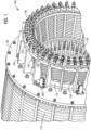
- FIG. 1 illustrates a schematic perspective partial view of a generator stator 100 having an end winding coil support assembly 200 according to an embodiment of the invention.
- the generator stator 100 has a stator core 110 and a core flange plate 120.
- the core flange plate 120 is mounted at each axial end of the stator core 110.
- the generator stator 100 has a plurality of end winding coils 140 extending outwardly from the core flange plate 120.
- the stator core 110 and the end winding coils 140 circumferentially form a bore 130 for accepting a rotor (not shown).
- the end winding coils 140 are circumferentially enclosed by an inner support ring 152 and an outer support ring 154 which are axially spaced apart from each other.
- the outer support ring 154 is axially disposed outwardly from the inner support ring 152.
- Outer braces 150 are axially disposed between the inner support ring 152 and outer support ring 154.
- the outer braces 150 may be circumferentially spaced apart from each other around the end winding coils 140.
- a plurality of holes 156 may be circumferentially disposed on the inner support ring 152 and the outer support ring 154 and axially disposed on the outer braces 150.
- Bandages (not shown) may pass through the holes 156 and the end winding coils 140 for consolidating the end winding coils 140.
- the generator stator 100 includes a plurality of end winding coil support assemblies 200. As shown in the exemplary embodiment of FIG. 1 , the end winding coil support assemblies 200 may be secured to the core flange plate 120. The end winding coil support assemblies 200 may be circumferentially disposed along an outer peripheral surface of the core flange plate 120 and spaced apart from each other. The end winding coil support assemblies 200 extend axially outwardly from the core flange plate 120. The end winding coil support assemblies 200 are attached to the inner support ring 152 for supporting the inner support ring 152. The end winding coil support assemblies 200 may include holes 232.
- Bandages may pass through the holes 232 in the end winding coil support assemblies 200 and the holes 156 in the inner support ring 152 for further connection of the end winding coil support assemblies 200 to the inner support ring 152.
- a total number of the end winding coil support assemblies 200 are determined to provide optimum performance of the generator stator 100. For example, a total number of 6, 7 or 8 end winding coil support assemblies 200 may be circumferentially disposed along the outer peripheral surface of the core flange plate 120 and the inner support ring 152. Other total number of end winding coil support assemblies 200 may also be used.
- the end winding coil support assemblies 200 may also be attached to the outer support ring 154.
- the end winding coil support assemblies 200 may also be attached to the end winding coils 140.
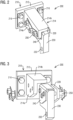
- FIG. 2 illustrates a schematic perspective view of a generator stator end winding support assembly 200 according to an embodiment of the invention.
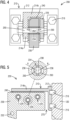
- FIG. 3 illustrates a schematic exploded view of the generator stator end winding support assembly 200 as shown in FIG. 2 .
- FIG. 4 illustrates a schematic front view of the generator stator end winding support assembly 200 as shown in FIG. 2 .
- FIG. 5 illustrates a schematic side view of a generator stator end winding support assembly 200 as shown in FIG. 2 .
- the end winding coil support assembly 200 includes a bracket 210.
- the bracket 210 includes a first bracket plate 212 for securing the end winding coil support assembly 200 to the core flange plate 120 by fasteners 216, such as bolts.
- the first bracket plate 212 may be secured to the core flange plate 120 by other means, such as by welding, or by dovetail joint.
- the first bracket plate 212 may be rigidly secured to the core flange plate 120.
- the bracket 210 includes a second bracket plate 214 extending axially outwardly from the first bracket plate 212.
- the second bracket plate 214 may be attached to the first bracket plate 212 as an integral piece, such as by welding.
- the second bracket plate 214 may be perpendicular to the first bracket plate 212.
- the second bracket plate 214 may have an L-shape having a radial plate 214a extending radially and a tangential plate 214b extending tangentially.
- the bracket 210 may be made from austenitic steel.
- the end winding coil support assembly 200 also includes a backup plate 220.
- the backup plate 220 is arranged in parallel to the radial plate 214a of the L-shaped second bracket plate 214 forming a U-shaped space with an opening downward to the inner support ring 152.
- a brace 230 is disposed between the backup plate 220 and the L-shaped second bracket plate 214 radially extending therethrough the U-shaped space downwardly.
- Lower section of the brace 230 may be L-shaped and interfaces with the inner support ring 152 in both axial and radial directions.
- the brace 230 may be connected to the inner support ring 152 by resin impregnated conformable layer that is placed in notches (not shown) in the inner support ring 152.
- the lower section of the brace 230 may have hole 232 for additionally connection to the inner support ring 152 by bandages.
- Mat (not shown) may be disposed between the brace 230 and the inner support ring 152. Resin impregnated conformable material may be used for this purpose.
- the brace 230 may be made from insulation materials so that no free floating potential occurs. The insulation materials may include glass-fabric material.
- An elastic layer 240 is disposed around the brace 230 at interfaces between the brace 230 and the second bracket plate 214 and between the brace 230 and the backup plate 220.
- the elastic layer 240 may be made from a material that has a compliant compression characteristic to a stress such that the elastic layer 240 is able to accommodate vibrations and damping of the generator stator 100 during operation.
- the elastic layer 240 may be made from materials, such as elastomers, viscoelastic, rubbers, silicon, Viton ® , nitrile, or spring materials such as metals, composites, etc.
- the elastic layer 240 may be adhesively attached to the brace 230, such as by glue.
- the elastic layer 240 may be bonded to the brace 230.
- At least one stud 250 extends through the radial plate 214a of the second bracket plate 214, the backup plate 220, the brace 230 and the elastic layer 240 for clamping said components together.
- the brace 230 includes an aperture 234 for the stud 250 extending therethrough.
- the aperture 234 is larger than a diameter of the stud 250 so that the brace 230 may be movable relative to the bracket 210 rigidly secured to the core flange plate 120 and thus the inner support ring 152 is movable relative to the bracket 210 secured to the core flange plate 120.
- a plurality of studs 250 may be used for clamping the components together.
- a plurality of apertures 234 are arranged in the brace 230 for the studs 250 extending therethrough.
- the apertures 234 may be arranged in the brace 230 in a way to maximize distance between the apertures 234 for a strength consideration of the brace 230.
- the end winding coil support assembly 200 has three studs 250 extending therethrough the radial plate 214a of the second bracket plate 214, the backup plate 220, the brace 230 and the elastic layer 240.
- a sleeve 260 is disposed in the aperture 234.
- the sleeve 260 encloses the stud 250 extending therethrough the aperture 234.
- the sleeve 260 is held between the radial plate 214a of the second bracket plate 214 and the backup plate 220 by a clamping force of the stud 250.
- the sleeve 260 sets up a gap 262 at interfaces between the brace 230 and the radial plate 214a and between the brace 230 and the backup plate 220 in which the elastic layer 240 is disposed.
- the gap 262 defines a compression of the elastic layer 240 under stress induced in operation of the generator stator 100 such that the elastic layer 240 may accommodate vibrations and damping of the generator stator 100 during operation. Compression of the elastic layer 240 enables the brace 230 to move relative to the bracket 210 rigidly secured to the core flange plate 120 during operation.
- the inner support ring 152 connected to the brace 230 may move with the brace 230.
- the end winding coil support assembly 200 may thus flexibly support the end winding coils 140.
- the sleeve 260 may be made from materials which do not deform by the clamping force of the stud 250.
- a plurality of different load conditions may be applied.
- Different load conditions require the end winging coil support assembly 200 to provide different flexibility and stiffness support.
- flexibility is required to reduce variables, such as forces and resulting strains due to thermal expansion, while stiffness is required to control magnitudes of steady state vibration and to control variables, such as natural frequency of the end winging coil support assembly 200.
- the end winding coil support assembly 200 uses a nonlinear nature of the elastic layer 240 to control these variables. The flexibility and stiffness of the support may be controlled by amount of compression of the elastic layer 240.
- a clamping force of the stud 250 may be adjustable so that the sleeve 260 may set up a gap 262 for defining a compression of the elastic layer 240 based on load condition requirements.
- the elastic layer 240 may be selected to have a desired compression characteristic for controlling flexibility and stiffness support based on load condition requirements.
- thickness of the elastic layer 240 may be defined based on load condition requirements.
- the elastic layer 240 may be a sheet of rubber. Thickness of the elastic layer 240 may be about 5 mm. Compression of the elastic layer 240 may also control strains due to abnormal operating conditions such as three phase circuits and control amount of damping of the end winging coil support assembly 200 for dynamic response.
- FIG. 5 An enlarged view of the aperture 234 is illustrated in FIG. 5 .
- the aperture 234 has a shape of two semi circles 236 axially oriented opposite to each other.
- the two semi circles 236 are connected by an axial section 238.
- Each semi circle 236 has a radius that is larger than a radius of the sleeve 260.
- the radius of the sleeve 260 is larger than a radius of the stud 250 extending therethrough.
- the larger dimension of the aperture 234 and the elastic layer 240 disposed around the brace 230 enable the brace 230 to be movable relative to the bracket 210 secured to the core flange plate 120 during operation.
- a gap 270 is arranged between an axial inboard end of the brace 230 and the first bracket plate 212 secured to the core flange plate 120 for tolerance of an axial movement of the brace 230.
- Dimensions of the aperture 234, the stud 250 and the sleeve 260 are determined based on load condition requirements. For example, a diameter of the stud 250 may be around 20 mm. A diameter of the sleeve 260 may be around 26 mm. A radius of each semi circle 236 may be around 16 mm. Length of the axial section 238 connecting the two semi circles 236 may be around 5 mm.
- the proposed generator stator end winding coil support assembly 200 may provide a balance between desired flexibility and stiffness support to the end winding coils 140 in different load conditions.
- the balance may be achieved by adjusting a clamping force of the stud 250 so that the sleeve 260 may set up a desired gap 262 to define a compression of the elastic layer 240.
- the balance may be achieved by selecting the elastic layer 240 having a desired compression characteristic.
- the balance may be achieved by a desired thickness of the elastic layer 240.
- the proposed generator stator end winding coil support assembly 200 increases reliability of the generator stator 100 and reduces design cycle time and cost of the generator stator 100.
- the proposed generator stator end winding coil support assembly 200 also reduces manufacturing cost of the generator stator 100.
Landscapes
- Engineering & Computer Science (AREA)
- Power Engineering (AREA)
- Insulation, Fastening Of Motor, Generator Windings (AREA)
Claims (8)
- Ensemble (200) de soutien de bobines d'enroulements d'extrémité destiné à soutenir des bobines (140) d'enroulements d'extrémité d'un stator (100) de générateur comportant un noyau (110) de stator, une plaque (120) de flasque de noyau montée à une extrémité axiale du noyau (110) de stator et une bague intérieure (152) de soutien enveloppant circonférentiellement les bobines (140) d'enroulements d'extrémité s'étendant axialement vers l'extérieur à partir de la plaque (120) de flasque de noyau,
l'ensemble (200) de soutien de bobines d'enroulements d'extrémité comportant :un support (210) fixé de manière rigide à la plaque (120) de flasque de noyau ;une plaque (220) d'appui ;une bride (230) disposée entre le support (210) et la plaque (220) d'appui et s'étendant radialement vers l'intérieur, liée à la bague intérieure (152) de soutien ; etune couche élastique (240) disposée autour de la bride (230) à une interface entre le support (210) et la plaque (220) d'appui, au moins un goujon (250) s'étendant à travers le support (210), la bride (230), la couche élastique (240) et la plaque (220) d'appui pour serrer lesdits composants ensemble,la bride (230) comportant une ouverture (234) qui est plus grande qu'un diamètre du goujon (250) s'étendant à travers celle-ci, un manchon (260) étant disposé dans l'ouverture (234) et enveloppant le goujon (250), l'ouverture (234) de la bride (230) étant plus grande qu'un diamètre extérieur du manchon (260), l'ouverture (234) comportant deux demi-cercles (236) orientés axialement à l'opposé l'un de l'autre et reliés par une section axiale (238), un rayon des demi-cercles (236) étant plus grand que le rayon extérieur du manchon (260),le manchon (260) ménageant un écartement (262) à des interfaces entre la bride (230) et le support (210) et entre la bride (230) et la plaque (220) d'appui qui définit une compression de la couche élastique (240) pour l'adaptation aux vibrations et l'amortissement pendant le fonctionnement du stator (100) de générateur,la compression de la couche élastique (240) permettant à la bride (230) d'être mobile par rapport au support (210) fixé de manière rigide à la plaque (120) de flasque de noyau pour soutenir de manière souple les bobines (140) d'enroulements d'extrémité. - Ensemble selon la revendication 1, une force de serrage du goujon (250) étant réglable pour réguler la souplesse et la rigidité du support en fonction d'une condition de charge pendant le fonctionnement.
- Ensemble selon la revendication 1, la couche élastique (240) étant sélectionnée de façon à présenter une caractéristique de compression pour réguler la souplesse et la rigidité du support en fonction d'une condition de charge pendant le fonctionnement.
- Ensemble selon la revendication 1, le support (210) comportant une première plaque (212) de support et une seconde plaque (214) de support, la première plaque (212) de support étant fixée de manière rigide à la plaque (120) de flasque de noyau par des organes (216) d'assemblage, et la seconde plaque (214) de support étant liée à la première plaque (212) de support perpendiculairement et prolongée axialement vers l'extérieur.
- Ensemble selon les revendications 1 à 4, un écartement (270) existant entre une extrémité axiale d'intérieur de la bride (230) et la première plaque (212) de support pour admettre un mouvement axial de la bride (230).
- Procédé de soutien de bobines (140) d'enroulements d'extrémité d'un stator (100) de générateur, comportant les étapes consistant à :mettre en place un stator (100) de générateur, le stator (100) de générateur comportant un noyau (110) de stator, une plaque (120) de flasque de noyau monté à une extrémité axiale du noyau (110) de stator et une bague intérieure (152) de soutien enveloppant circonférentiellement les bobines (140) d'enroulements d'extrémité s'étendant axialement vers l'extérieur à partir de la plaque (120) de flasque de noyau, fixer de manière rigide un support (210) à la plaque (120) de flasque de noyau ;disposer une bride (230) entre le support (210) et une plaque (220) d'appui et s'étendant radialement vers l'intérieur liée à la bague intérieure (152) de soutien ;disposer une couche élastique (240) autour de la bride (230) à une interface entre le support (230) et la plaque (220) d'appui ; etserrer ensemble la plaque (220) d'appui, la bride (230), la couche élastique (240) et le support par au moins un goujon s'étendant à travers ceux-ci,la bride (230) comportant une ouverture (234) qui est plus grande qu'un diamètre du goujon (250) s'étendant à travers celle-ci, un manchon (260) étant disposé dans l'ouverture (234) et enveloppant le goujon (250), l'ouverture (234) de la bride (230) étant plus grande qu'un diamètre extérieur du manchon (260), l'ouverture (234) comportant deux demi-cercles (236) orientés axialement à l'opposé l'un de l'autre et reliés par une section axiale (238), un rayon des demi-cercles (236) étant plus grand que le rayon extérieur du manchon (260),le manchon (260) ménageant un écartement (262) à des interfaces entre la bride (230) et le support (230) et entre la bride (230) et la plaque (220) d'appui qui définit une compression de la couche élastique (240) pour l'adaptation aux vibrations et l'amortissement pendant le fonctionnement du stator (100) de générateur, etla compression de la couche élastique (240) permettant à la bride (230) d'être mobile par rapport au support (230) fixé de manière rigide à la plaque (120) de flasque de noyau pour soutenir de manière souple les bobines (140) d'enroulements d'extrémité.
- Procédé selon la revendication 6, comportant en outre le réglage d'une force de serrage du goujon (250) pour réguler la souplesse et la rigidité du support en fonction d'une condition de charge pendant le fonctionnement.
- Stator (100) de générateur comportant une pluralité d'ensembles (200) de soutien de bobines d'enroulements d'extrémité selon l'une quelconque des revendications 1 à 5, et le stator de générateur comportant :un noyau (110) de stator ;une plaque (120) de flasque de noyau montée à une extrémité axiale du noyau (110) de stator ;une pluralité de bobines (140) d'enroulements d'extrémité s'étendant axialement vers l'extérieur à partir de la plaque (102) de flasque de noyau ; etune bague intérieure (152) de soutien située axialement à l'intérieur et enveloppant circonférentiellement les bobines (140) d'enroulements d'extrémité pour soutenir les bobines (140) d'enroulements d'extrémité ;la pluralité d'ensembles (200) de soutien de bobines d'enroulements d'extrémité étant disposée circonférentiellement le long d'une surface périphérique extérieure de la plaque (102) de flasque de noyau et s'étendant axialement vers l'extérieur à partir de la plaque (102) de flasque de noyau et étant liée à la bague intérieure (152) de soutien.
Applications Claiming Priority (1)
| Application Number | Priority Date | Filing Date | Title |
|---|---|---|---|
| PCT/US2018/024517 WO2019190474A1 (fr) | 2018-03-27 | 2018-03-27 | Ensemble support de bobine d'enroulement d'extrémité de stator de générateur |
Publications (3)
| Publication Number | Publication Date |
|---|---|
| EP3747111A1 EP3747111A1 (fr) | 2020-12-09 |
| EP3747111C0 EP3747111C0 (fr) | 2024-10-23 |
| EP3747111B1 true EP3747111B1 (fr) | 2024-10-23 |
Family
ID=61972610
Family Applications (1)
| Application Number | Title | Priority Date | Filing Date |
|---|---|---|---|
| EP18718046.8A Active EP3747111B1 (fr) | 2018-03-27 | 2018-03-27 | Support de tete d'enroulement d'un stator de generateur |
Country Status (5)
| Country | Link |
|---|---|
| US (1) | US11437874B2 (fr) |
| EP (1) | EP3747111B1 (fr) |
| JP (1) | JP7094384B2 (fr) |
| PL (1) | PL3747111T3 (fr) |
| WO (1) | WO2019190474A1 (fr) |
Families Citing this family (4)
| Publication number | Priority date | Publication date | Assignee | Title |
|---|---|---|---|---|
| DE102020129828A1 (de) | 2020-11-12 | 2022-05-12 | Dr. Ing. H.C. F. Porsche Aktiengesellschaft | Stator einer elektrischen Maschine |
| CN112688453A (zh) * | 2020-12-09 | 2021-04-20 | 诺丁汉(余姚)智能电气化研究院有限公司 | 一种端部绕组磁通电机 |
| CN114142651B (zh) * | 2021-11-12 | 2025-08-12 | 上海电气电站设备有限公司 | 一种大型发电机定子端部柔性自适应连接结构 |
| CN120533384A (zh) * | 2025-06-09 | 2025-08-26 | 无锡正大物流系统工程有限公司 | 一种电机焊接加工装置焊接辅助配件及操作方法 |
Family Cites Families (38)
| Publication number | Priority date | Publication date | Assignee | Title |
|---|---|---|---|---|
| US3975655A (en) | 1972-06-26 | 1976-08-17 | Kraftwerk Union Aktiengesellschaft | Coil end support for the stator winding of electric machines such as turbo generators or the like |
| JPS5934482U (ja) | 1982-08-26 | 1984-03-03 | 日産自動車株式会社 | モ−タの回転子 |
| US4525642A (en) | 1984-04-05 | 1985-06-25 | Westinghouse Electric Corp. | Turbine generator with stator end winding support assembly including resilient bracket |
| US4642493A (en) * | 1985-04-25 | 1987-02-10 | Urban Transportation Development Corporation Ltd. | Integrally air cooled linear induction motor |
| US4618795A (en) * | 1985-04-10 | 1986-10-21 | Westinghouse Electric Corp. | Turbine generator stator end winding support assembly with decoupling from the core |
| DE3612819A1 (de) * | 1986-04-16 | 1987-10-22 | Siemens Ag | Anordnung zur befestigung einer luftspaltwicklung und verfahren zu ihrer montage und demontage |
| US4894573A (en) * | 1987-12-11 | 1990-01-16 | Northern Engineering Industries Plc | Rotary electrical machines |
| US4942326A (en) * | 1989-04-19 | 1990-07-17 | Westinghouse Electric Corp. | Biased securement system for end winding conductor |
| ATE103121T1 (de) * | 1989-09-20 | 1994-04-15 | Asea Brown Boveri | Vorrichtung zur fixierung der windungsenden einer statorwicklung in einer dynamoelektrischen maschine. |
| US5355046A (en) * | 1989-12-15 | 1994-10-11 | Klaus Weigelt | Stator end-winding system and a retrofitting set for same |
| CH680546A5 (fr) * | 1989-12-15 | 1992-09-15 | Klaus Weigelt Dr Ing | |
| US5117140A (en) * | 1991-05-13 | 1992-05-26 | Westinghouse Electric Corp. | Stator stabilizing assemblies |
| DE4302989A1 (de) * | 1993-02-03 | 1994-08-04 | Abb Management Ag | Vorrichtung zur Halterung der Windungsenden einer Statorwicklung in einer dynamoelektrischen Maschine |
| US5650679A (en) * | 1993-03-18 | 1997-07-22 | Boggs, Iii; Paul Dewey | Eddy current drive |
| DE4322269A1 (de) * | 1993-07-05 | 1995-01-12 | Abb Management Ag | Vorrichtung zur Halterung der Windungsenden einer Statorwicklung in einer dynamoelektrischen Maschine |
| US5530305A (en) * | 1994-01-13 | 1996-06-25 | Outboard Marine Corporation | Marine engine alternator construction |
| US5373211A (en) * | 1994-02-14 | 1994-12-13 | Westinghouse Electric Corporation | Turbine generator stator end floating winding support |
| DE4406400A1 (de) * | 1994-02-26 | 1995-08-31 | Abb Management Ag | Vorrichtung zur Halterung der Windungsenden einer Statorwicklung in einer dynamoelektrischen Maschine |
| JP3536472B2 (ja) * | 1995-09-27 | 2004-06-07 | 株式会社デンソー | 交流発電機 |
| US5752774A (en) * | 1996-10-22 | 1998-05-19 | Mohawk Innovative Technology, Inc. | Zero clearance auxiliary bearing for providing rotor shock tolerance |
| US5798595A (en) * | 1996-12-30 | 1998-08-25 | Westinghouse Electric Corporation | Vibrational control system for stator coils |
| DE69735893T2 (de) * | 1997-10-17 | 2007-04-19 | Denso Corp., Kariya | Wechselstromgenerator für kraftfahrzeuge |
| US6104116A (en) * | 1999-04-16 | 2000-08-15 | Siemens Westinghouse Power Corporation | Generator stator keybar compliant clamp and current shunt |
| US6218759B1 (en) * | 1999-12-02 | 2001-04-17 | General Electric Co. | Generator core end support ring for applying a radial outward force to armature windings outboard of stator core slot dovetails |
| US6570292B2 (en) * | 2001-05-15 | 2003-05-27 | General Electric Company | High temperature super-conducting rotor coil support with split coil housing and assembly method |
| DE10310306A1 (de) * | 2002-03-12 | 2003-09-25 | Alstom Switzerland Ltd | Vorrichtung zum Spannen einer Statorwicklung |
| US6858967B2 (en) * | 2003-06-18 | 2005-02-22 | Siemens Westinghouse Power Corporation | Ring assembly for mechanically clamping a stator core with core-end magnetic flux shunts in a dynamoelectric machine |
| US7886426B2 (en) * | 2008-07-22 | 2011-02-15 | Honda Motor Co., Ltd. | Stator manufacturing apparatus |
| EP2582019A1 (fr) * | 2011-10-14 | 2013-04-17 | Siemens Aktiengesellschaft | Ajuster la rigidité de la tête de bobine d'une machine électrique |
| US9071096B2 (en) * | 2011-11-09 | 2015-06-30 | Siemens Energy, Inc. | Clamping structure for a stator core |
| EP3032703B1 (fr) * | 2012-08-31 | 2018-08-29 | Lappeenranta University of Technology | Machine électrique |
| US9768509B2 (en) * | 2013-08-09 | 2017-09-19 | Sumida Corporation | Antenna coil component, antenna unit, and method of manufacturing the antenna coil component |
| US20150171715A1 (en) * | 2013-12-13 | 2015-06-18 | James F. Pettit | Repair method of spring assemblies in a stator core |
| US20150171719A1 (en) * | 2013-12-13 | 2015-06-18 | James F. Pettit | Spring assemblies for supporting a stator core in a stator frame |
| JP6282916B2 (ja) | 2014-04-10 | 2018-02-21 | 山洋電気株式会社 | 冷却ファンの取付構造 |
| US11070115B2 (en) * | 2016-01-12 | 2021-07-20 | Prototus, Ltd. | Motor/generator system and method |
| JP7293627B2 (ja) * | 2018-12-05 | 2023-06-20 | 株式会社デンソー | 回転電機及び回転電機の製造方法 |
| JP7226162B2 (ja) * | 2019-02-25 | 2023-02-21 | 株式会社デンソー | 回転電機 |
-
2018
- 2018-03-27 US US16/970,803 patent/US11437874B2/en active Active
- 2018-03-27 JP JP2020551890A patent/JP7094384B2/ja active Active
- 2018-03-27 PL PL18718046.8T patent/PL3747111T3/pl unknown
- 2018-03-27 EP EP18718046.8A patent/EP3747111B1/fr active Active
- 2018-03-27 WO PCT/US2018/024517 patent/WO2019190474A1/fr not_active Ceased
Also Published As
| Publication number | Publication date |
|---|---|
| JP7094384B2 (ja) | 2022-07-01 |
| US11437874B2 (en) | 2022-09-06 |
| EP3747111A1 (fr) | 2020-12-09 |
| EP3747111C0 (fr) | 2024-10-23 |
| JP2021518737A (ja) | 2021-08-02 |
| WO2019190474A1 (fr) | 2019-10-03 |
| US20210111597A1 (en) | 2021-04-15 |
| PL3747111T3 (pl) | 2025-02-24 |
Similar Documents
| Publication | Publication Date | Title |
|---|---|---|
| EP3747111B1 (fr) | Support de tete d'enroulement d'un stator de generateur | |
| US7923890B2 (en) | Apparatus for generator stator mounting | |
| EP1835596B1 (fr) | Stator d'une machine électrique tournante | |
| US8791616B2 (en) | Electric machine with axial flux and permanent magnets | |
| JPH0256022B2 (fr) | ||
| CN102124212B (zh) | 风力发电装置及其组装方法 | |
| US10727705B2 (en) | Compression band shim pack for stator core, related stator and generator | |
| KR20100124673A (ko) | 발전기 고정자 장착용 시스템 및 방법 | |
| US9692262B2 (en) | Suspension structures | |
| US4341968A (en) | Support means for high-temperature generator stators | |
| JP2019004568A (ja) | 回転電機のステータ | |
| KR20160065960A (ko) | 코어 서포트 시스템용 개선된 발전기 스프링 바 | |
| EP2884628A2 (fr) | Ensembles à ressort pour supporter un noyau de stator dans une carcasse de stator | |
| CN109891709B (zh) | 定子叠片组区段板,定子叠片组,和具有其的发电机和风能设施 | |
| KR20200122250A (ko) | 유도 기계의 로터 및 로터의 케이지형 권선 조립 방법 | |
| EP2884627A2 (fr) | Procédé de réparation d'ensembles de ressorts dans un noyau de stator | |
| CN103875162A (zh) | 调整电机的定子端绕组中的刚度 | |
| EP3086446B1 (fr) | Rotor enroulé pour machine électrique tournante | |
| RU2550085C1 (ru) | Устройство крепления лобовых частей обмотки статора турбогенератора | |
| CN210167881U (zh) | 一种汽轮发电机定子线圈端部的弹性支撑结构 | |
| JPH07167132A (ja) | スラスト軸受装置 | |
| CN116707253A (zh) | 用于驱动模块的动平衡环、驱动模块及转子动平衡方法 | |
| JP5610939B2 (ja) | 回転電機および回転電機の固定子 | |
| JPH11355997A (ja) | 回転電機の回転子コイル端部支持装置 |
Legal Events
| Date | Code | Title | Description |
|---|---|---|---|
| STAA | Information on the status of an ep patent application or granted ep patent |
Free format text: STATUS: UNKNOWN |
|
| STAA | Information on the status of an ep patent application or granted ep patent |
Free format text: STATUS: THE INTERNATIONAL PUBLICATION HAS BEEN MADE |
|
| PUAI | Public reference made under article 153(3) epc to a published international application that has entered the european phase |
Free format text: ORIGINAL CODE: 0009012 |
|
| STAA | Information on the status of an ep patent application or granted ep patent |
Free format text: STATUS: REQUEST FOR EXAMINATION WAS MADE |
|
| 17P | Request for examination filed |
Effective date: 20200901 |
|
| AK | Designated contracting states |
Kind code of ref document: A1 Designated state(s): AL AT BE BG CH CY CZ DE DK EE ES FI FR GB GR HR HU IE IS IT LI LT LU LV MC MK MT NL NO PL PT RO RS SE SI SK SM TR |
|
| AX | Request for extension of the european patent |
Extension state: BA ME |
|
| RIN1 | Information on inventor provided before grant (corrected) |
Inventor name: FORD, KEEGAN M. Inventor name: STEINS, HENDRIK Inventor name: EBBERT, THOMAS Inventor name: VERBANIC, MICHAEL Inventor name: SPIN, PHILIPP Inventor name: WERKMEISTER, STEPHAN Inventor name: HUMPHRIES, BENJAMIN TODD |
|
| DAV | Request for validation of the european patent (deleted) | ||
| DAX | Request for extension of the european patent (deleted) | ||
| STAA | Information on the status of an ep patent application or granted ep patent |
Free format text: STATUS: EXAMINATION IS IN PROGRESS |
|
| 17Q | First examination report despatched |
Effective date: 20220428 |
|
| GRAP | Despatch of communication of intention to grant a patent |
Free format text: ORIGINAL CODE: EPIDOSNIGR1 |
|
| STAA | Information on the status of an ep patent application or granted ep patent |
Free format text: STATUS: GRANT OF PATENT IS INTENDED |
|
| INTG | Intention to grant announced |
Effective date: 20240605 |
|
| GRAS | Grant fee paid |
Free format text: ORIGINAL CODE: EPIDOSNIGR3 |
|
| GRAA | (expected) grant |
Free format text: ORIGINAL CODE: 0009210 |
|
| STAA | Information on the status of an ep patent application or granted ep patent |
Free format text: STATUS: THE PATENT HAS BEEN GRANTED |
|
| AK | Designated contracting states |
Kind code of ref document: B1 Designated state(s): AL AT BE BG CH CY CZ DE DK EE ES FI FR GB GR HR HU IE IS IT LI LT LU LV MC MK MT NL NO PL PT RO RS SE SI SK SM TR |
|
| REG | Reference to a national code |
Ref country code: GB Ref legal event code: FG4D |
|
| REG | Reference to a national code |
Ref country code: CH Ref legal event code: EP |
|
| REG | Reference to a national code |
Ref country code: DE Ref legal event code: R096 Ref document number: 602018075697 Country of ref document: DE |
|
| REG | Reference to a national code |
Ref country code: IE Ref legal event code: FG4D |
|
| U01 | Request for unitary effect filed |
Effective date: 20241031 |
|
| U07 | Unitary effect registered |
Designated state(s): AT BE BG DE DK EE FI FR IT LT LU LV MT NL PT RO SE SI Effective date: 20241113 |
|
| PG25 | Lapsed in a contracting state [announced via postgrant information from national office to epo] |
Ref country code: HR Free format text: LAPSE BECAUSE OF FAILURE TO SUBMIT A TRANSLATION OF THE DESCRIPTION OR TO PAY THE FEE WITHIN THE PRESCRIBED TIME-LIMIT Effective date: 20241023 Ref country code: IS Free format text: LAPSE BECAUSE OF FAILURE TO SUBMIT A TRANSLATION OF THE DESCRIPTION OR TO PAY THE FEE WITHIN THE PRESCRIBED TIME-LIMIT Effective date: 20250223 |
|
| PG25 | Lapsed in a contracting state [announced via postgrant information from national office to epo] |
Ref country code: ES Free format text: LAPSE BECAUSE OF FAILURE TO SUBMIT A TRANSLATION OF THE DESCRIPTION OR TO PAY THE FEE WITHIN THE PRESCRIBED TIME-LIMIT Effective date: 20241023 |
|
| PG25 | Lapsed in a contracting state [announced via postgrant information from national office to epo] |
Ref country code: NO Free format text: LAPSE BECAUSE OF FAILURE TO SUBMIT A TRANSLATION OF THE DESCRIPTION OR TO PAY THE FEE WITHIN THE PRESCRIBED TIME-LIMIT Effective date: 20250123 |
|
| PG25 | Lapsed in a contracting state [announced via postgrant information from national office to epo] |
Ref country code: GR Free format text: LAPSE BECAUSE OF FAILURE TO SUBMIT A TRANSLATION OF THE DESCRIPTION OR TO PAY THE FEE WITHIN THE PRESCRIBED TIME-LIMIT Effective date: 20250124 |
|
| PGFP | Annual fee paid to national office [announced via postgrant information from national office to epo] |
Ref country code: PL Payment date: 20250310 Year of fee payment: 8 |
|
| PG25 | Lapsed in a contracting state [announced via postgrant information from national office to epo] |
Ref country code: RS Free format text: LAPSE BECAUSE OF FAILURE TO SUBMIT A TRANSLATION OF THE DESCRIPTION OR TO PAY THE FEE WITHIN THE PRESCRIBED TIME-LIMIT Effective date: 20250123 |
|
| U20 | Renewal fee for the european patent with unitary effect paid |
Year of fee payment: 8 Effective date: 20250325 |
|
| PG25 | Lapsed in a contracting state [announced via postgrant information from national office to epo] |
Ref country code: SM Free format text: LAPSE BECAUSE OF FAILURE TO SUBMIT A TRANSLATION OF THE DESCRIPTION OR TO PAY THE FEE WITHIN THE PRESCRIBED TIME-LIMIT Effective date: 20241023 |
|
| PG25 | Lapsed in a contracting state [announced via postgrant information from national office to epo] |
Ref country code: SK Free format text: LAPSE BECAUSE OF FAILURE TO SUBMIT A TRANSLATION OF THE DESCRIPTION OR TO PAY THE FEE WITHIN THE PRESCRIBED TIME-LIMIT Effective date: 20241023 |
|
| PG25 | Lapsed in a contracting state [announced via postgrant information from national office to epo] |
Ref country code: CZ Free format text: LAPSE BECAUSE OF FAILURE TO SUBMIT A TRANSLATION OF THE DESCRIPTION OR TO PAY THE FEE WITHIN THE PRESCRIBED TIME-LIMIT Effective date: 20241023 |
|
| PLBE | No opposition filed within time limit |
Free format text: ORIGINAL CODE: 0009261 |
|
| STAA | Information on the status of an ep patent application or granted ep patent |
Free format text: STATUS: NO OPPOSITION FILED WITHIN TIME LIMIT |
|
| 26N | No opposition filed |
Effective date: 20250724 |
|
| PG25 | Lapsed in a contracting state [announced via postgrant information from national office to epo] |
Ref country code: MC Free format text: LAPSE BECAUSE OF FAILURE TO SUBMIT A TRANSLATION OF THE DESCRIPTION OR TO PAY THE FEE WITHIN THE PRESCRIBED TIME-LIMIT Effective date: 20241023 |
|
| REG | Reference to a national code |
Ref country code: CH Ref legal event code: H13 Free format text: ST27 STATUS EVENT CODE: U-0-0-H10-H13 (AS PROVIDED BY THE NATIONAL OFFICE) Effective date: 20251023 |
|
| GBPC | Gb: european patent ceased through non-payment of renewal fee |
Effective date: 20250327 |
|
| PG25 | Lapsed in a contracting state [announced via postgrant information from national office to epo] |
Ref country code: GB Free format text: LAPSE BECAUSE OF NON-PAYMENT OF DUE FEES Effective date: 20250327 |
|
| PG25 | Lapsed in a contracting state [announced via postgrant information from national office to epo] |
Ref country code: CH Free format text: LAPSE BECAUSE OF NON-PAYMENT OF DUE FEES Effective date: 20250331 |
|
| PG25 | Lapsed in a contracting state [announced via postgrant information from national office to epo] |
Ref country code: IE Free format text: LAPSE BECAUSE OF NON-PAYMENT OF DUE FEES Effective date: 20250327 |