EP3747227B1 - Procédé de fonctionnement d'un équipement d'infrastructure de réseau, procédé correspondant de fonctionnement d'un dispositif terminal, appareils correspondants et circuits intégrés - Google Patents
Procédé de fonctionnement d'un équipement d'infrastructure de réseau, procédé correspondant de fonctionnement d'un dispositif terminal, appareils correspondants et circuits intégrés Download PDFInfo
- Publication number
- EP3747227B1 EP3747227B1 EP19701685.0A EP19701685A EP3747227B1 EP 3747227 B1 EP3747227 B1 EP 3747227B1 EP 19701685 A EP19701685 A EP 19701685A EP 3747227 B1 EP3747227 B1 EP 3747227B1
- Authority
- EP
- European Patent Office
- Prior art keywords
- random access
- terminal device
- access procedure
- message
- network infrastructure
- Prior art date
- Legal status (The legal status is an assumption and is not a legal conclusion. Google has not performed a legal analysis and makes no representation as to the accuracy of the status listed.)
- Active
Links
Images



Classifications
-
- H—ELECTRICITY
- H04—ELECTRIC COMMUNICATION TECHNIQUE
- H04W—WIRELESS COMMUNICATION NETWORKS
- H04W72/00—Local resource management
- H04W72/20—Control channels or signalling for resource management
- H04W72/23—Control channels or signalling for resource management in the downlink direction of a wireless link, i.e. towards a terminal
-
- H—ELECTRICITY
- H04—ELECTRIC COMMUNICATION TECHNIQUE
- H04W—WIRELESS COMMUNICATION NETWORKS
- H04W72/00—Local resource management
- H04W72/04—Wireless resource allocation
- H04W72/044—Wireless resource allocation based on the type of the allocated resource
- H04W72/0453—Resources in frequency domain, e.g. a carrier in FDMA
-
- H—ELECTRICITY
- H04—ELECTRIC COMMUNICATION TECHNIQUE
- H04W—WIRELESS COMMUNICATION NETWORKS
- H04W48/00—Access restriction; Network selection; Access point selection
- H04W48/16—Discovering, processing access restriction or access information
-
- H—ELECTRICITY
- H04—ELECTRIC COMMUNICATION TECHNIQUE
- H04W—WIRELESS COMMUNICATION NETWORKS
- H04W74/00—Wireless channel access
- H04W74/002—Transmission of channel access control information
-
- H—ELECTRICITY
- H04—ELECTRIC COMMUNICATION TECHNIQUE
- H04W—WIRELESS COMMUNICATION NETWORKS
- H04W74/00—Wireless channel access
- H04W74/08—Non-scheduled access, e.g. ALOHA
- H04W74/0833—Random access procedures, e.g. with 4-step access
-
- H—ELECTRICITY
- H04—ELECTRIC COMMUNICATION TECHNIQUE
- H04W—WIRELESS COMMUNICATION NETWORKS
- H04W74/00—Wireless channel access
- H04W74/08—Non-scheduled access, e.g. ALOHA
- H04W74/0833—Random access procedures, e.g. with 4-step access
- H04W74/0838—Random access procedures, e.g. with 4-step access using contention-free random access [CFRA]
Definitions
- the present disclosure relates to a method of operating a network infrastructure equipment, a network infrastructure equipment, an integrated circuitry for a network infrastructure equipment, a method of operating a terminal device, a terminal device and an integrated circuitry for a terminal device.
- Recent generation mobile telecommunication systems such as those based on the 3GPP defined UMTS and Long Term Evolution (LTE) architectures, are able to support a wider range of services than simple voice and messaging services offered by previous generations of mobile telecommunication systems.
- LTE Long Term Evolution
- a user is able to enjoy high data-rate applications such as mobile video streaming and mobile video conferencing that would previously only have been available via a fixed line data connection.
- newer generation mobile telecommunication systems it is also proposed for newer generation mobile telecommunication systems to support less complex services and devices which make use of the reliable and wide ranging coverage of newer generation mobile telecommunication systems without necessarily needing to rely on the high data rates available in such systems.
- Future wireless communications networks will therefore be expected to routinely and efficiently support communications with a wider range of devices associated with a wider range of data traffic profiles and types than current systems are optimised to support. For example it is expected future wireless communications networks will be expected to efficiently support communications with devices including reduced complexity devices, machine type communication (MTC) devices, high resolution video displays, virtual reality headsets and so on. Some of these different types of devices may be deployed in very large numbers, for example low complexity devices for supporting the "Internet of Things", and may typically be associated with the transmission of relatively small amounts of data with relatively high latency tolerance.
- MTC machine type communication
- the 3GPP has proposed in Release 13 of the 3GPP specifications to develop technologies for supporting narrowband (NB)-loT and so-called enhanced MTC (eMTC) operation using a LTE / 4G wireless access interface and wireless infrastructure. More recently there have been proposals to build on these ideas in Release 14 of the 3GPP specifications with so-called enhanced NB-loT (eNB-loT) and further enhanced MTC (feMTC), and in Release 15 of the 3GPP specifications with so-called further enhanced NB-IoT (feNB-loT) and even further enhanced MTC (efeMTC).
- eNB-loT enhanced NB-loT
- feMTC further enhanced MTC
- At least some devices making use of these technologies are expected to be low complexity and inexpensive devices requiring relatively infrequent communication of relatively low bandwidth data. It is further expected some of these types of device may be required to operate in areas of relatively poor coverage, for example, in a basement or other location with relatively high penetration loss (e.g. for smart meter type applications), or in remote locations (e.g. for remote monitoring applications), and this has given rise to proposals for enhancing coverage, for example using repeat transmissions.
- Figure 1 provides a schematic diagram illustrating some basic functionality of a mobile telecommunications network / system 100 operating generally in accordance with LTE principles, but which may also support other radio access technologies, and which may be adapted to implement embodiments of the disclosure as described herein.
- Various elements of Figure 1 and certain aspects of their respective modes of operation are well-known and defined in the relevant standards administered by the 3GPP (RTM) body, and also described in many books on the subject, for example, Holma H. and Toskala A [5].
- the network 100 includes a plurality of base stations 101 connected to a core network 102.
- Each base station provides a coverage area 103 (i.e. a cell) within which data can be communicated to and from terminal devices 104.
- Data is transmitted from base stations 101 to terminal devices 104 within their respective coverage areas 103 via a radio downlink.
- Data is transmitted from terminal devices 104 to the base stations 101 via a radio uplink.
- the core network 102 routes data to and from the terminal devices 104 via the respective base stations 101 and provides functions such as authentication, mobility management, charging and so on.
- Terminal devices may also be referred to as mobile stations, user equipment (UE), user terminal, mobile radio, communications device, and so forth.
- Base stations which are an example of network infrastructure equipment / network access nodes, may also be referred to as transceiver stations / nodeBs / e-nodeBs, g-nodeBs and so forth.
- transceiver stations / nodeBs / e-nodeBs, g-nodeBs and so forth.
- different terminology is often associated with different generations of wireless telecommunications systems for elements providing broadly comparable functionality.
- certain embodiments of the disclosure may be equally implemented in different generations of wireless telecommunications systems, and for simplicity certain terminology may be used regardless of the underlying network architecture. That is to say, the use of a specific term in relation to certain example implementations is not intended to indicate these implementations are limited to a certain generation of network that may be most associated with that particular terminology.
- a new RAT network may comprise communication cells that each comprise a controlling node in communication with a core network component and a plurality of distributed units (radio access nodes / remote transmission and reception points (TRPs)) within the cell.
- the distributed units may be responsible for providing the radio access interface for terminal devices connected to the NR network.
- Each distributed unit has a coverage area (radio access footprint) which together define the coverage of the communication cell.
- Each distributed unit includes transceiver circuitry for transmission and reception of wireless signals and processor circuitry configured to control the respective distributed units.
- the core network component of such a new RAT telecommunications system may be broadly considered to correspond with the core network 102 represented in Figure 1
- the respective controlling nodes and their associated distributed units / TRPs may be broadly considered to provide functionality corresponding to base stations of Figure 1 .
- the term network infrastructure equipment / access node may be used to encompass these elements and more conventional base station type elements of wireless telecommunications systems.
- the responsibility for scheduling transmissions which are scheduled on the radio interface between the respective distributed units and the terminal devices may lie with the controlling node / centralised unit and / or the distributed units / TRPs.
- a terminal device operating in this proposed new RAT architecture may thus exchange signalling with a first controlling node via one or more of the distributed units associated with the controlling node.
- the involvement of the distributed units in routing communications from the terminal device to a controlling node (controlling unit) may be transparent to the terminal device.
- this example represents merely one example of a proposed architecture for a new RAT telecommunications system in which approaches in accordance with the principles described herein may be adopted, and the functionality disclosed herein may also be applied in respect of wireless telecommunications systems having different architectures.
- certain embodiments of the disclosure as discussed herein may be implemented in wireless telecommunication systems / networks according to various different architectures, such as the example architecture shown in Figures 1 . It will be appreciated the specific wireless telecommunications architecture in any given implementation is not of primary significance to the principles described herein.
- the network infrastructure equipment / access node may comprise a base station, such as an LTE-type base station 101 as shown in Figure 1 which is adapted to provide functionality in accordance with the principles described herein, and in other examples the network infrastructure equipment may comprise a control unit / controlling node and / or a TRP in a new RAT architecture of the kind discussed above.
- RRC Radio Resource Control
- RRC_IDLE RRC idle mode
- RRC_CONNECTED RRC connected mode
- a terminal device in the idle mode may transition to connected mode, for example because it needs to transmit uplink data or respond to a paging request, by undertaking a random access procedure.
- the random access procedure involves the terminal device transmitting a preamble on a physical random access channel and so the procedure is commonly referred to as a RACH or PRACH procedure / process.
- a conventional way for a terminal device (UE) in RRC idle mode to exchange data with a network involves the terminal device first performing an RRC connection procedure (random access procedure) with the network.
- the RRC connection procedure involves the UE initially transmitting a random access request message (which may be triggered autonomously by the UE determining it has data to transmit to the network or in response to the network instructing the UE to connect to the network). This is followed by RRC control message exchange between the network and UE. After establishing an RRC connection and exchanging the relevant data, the UE may then perform RRC disconnection and move back into idle mode for power saving.
- This conventional approach may for convenience be referred to herein as a legacy approach.
- the random access procedure can be relatively inefficient if the amount of data to be communicated with the network is relatively small, for example in terms of signalling overhead and associated UE power usage.
- One approach for this is referred to as Early Data Transmission (EDT) and allows the UE to transmit and/or receive data during the Random Access process whilst in idle mode, thereby communicating the relevant data without the need to complete the establishment of an RRC connection, which can be particularly helpful for infrequent and short messages type of traffic.
- EDT Early Data Transmission
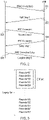
- FIG. 2 is a ladder diagram that schematically shows message exchange between a UE and an eNB in a typical random access procedure to establish an RRC connection, in this example in an LTE-based network.
- the UE starts the process in step S1 by transmitting a random access request on a physical random access channel (PRACH in an LTE context), i.e. a random access preamble (RACH preamble), to the eNB.
- PRACH physical random access channel
- RACH preamble random access preamble
- step S2 when the eNB detects this preamble it will respond with a Random Access Response message (RAR), which is also known as Message 2.
- RAR Random Access Response message
- the RAR is scheduled by DCI (downlink control information) carried on a physical downlink control channel, e.g.
- MTC machine type communication
- CSS Common Search Space
- the RAR itself is transmitted on a physical downlink shared channel (PDSCH) resource allocated via the DCI.
- PDSCH physical downlink shared channel
- the DCI is addressed to an RA-RNTI (random access radio network temporary identifier) which is derived from the time and frequency resources used to transmit the preamble in step S1 and the RAR will indicate which preamble the eNB has detected and is responding to. It may be noted it is possible that multiple UEs may transmit a random access request using the same PRACH preamble and the same time and frequency resources.
- RA-RNTI random access radio network temporary identifier
- the RAR of step S2 also contains an uplink grant for the preamble the network is responding to so that the UE that transmitted the preamble may use this uplink grant to transmit an RRC Connection Request message, also known as Message 3 to the eNB, in step S3.
- Message 3 also contains an indication of an identifier, ID, for the UE (e.g. a C-RNTI (cell radio network temporary identifier) or S-TMSI (system architecture evolution (SAE) temporary mobile subscriber identity) or a 40-bit random number generated by the UE.
- ID an indication of an identifier, for the UE (e.g. a C-RNTI (cell radio network temporary identifier) or S-TMSI (system architecture evolution (SAE) temporary mobile subscriber identity) or a 40-bit random number generated by the UE.
- SAE system architecture evolution
- Message 4 provides contention resolution functionality, for example using a terminal device identifier, such as C-RNTI or S-TMSI, transmitted in Message 3 (when a UE receives a Message 4 that contains a portion of the Message 3 containing the UE ID that it transmitted earlier, it knows that there was no contention on the Message 3 that it had transmitted).
- the RRC connection is complete when the UE transmits Message 5 in step S5 containing a RRC Connection Setup Complete message.
- a previously proposed approach for EDT in uplink is for additional data to be transmitted in association with the RRC connection request message, in Message 3 (step S3 in Figure 2 ).
- Message 3 For the legacy approach to random access, Message 3 carries only control messages and therefore has a limited Transport Block Size (TBS).
- TBS Transport Block Size
- the 3GPP group has agreed to allow for an increase in the TBS for Message 3 to 1000 bits.
- an eNB need not fulfil an EDT request by allocating resources for a TBS for Message 3 to 1000 bits, but the eNB can instead schedule a smaller TBS as for a legacy Message 3, for example having regard to overall resource availability.
- the UE may, for example, need to follow the legacy approach of establishing an RRC connection to communicate the data rather than using EDT.
- a set of available PRACH preambles be partitioned such that a sub-group of PRACH preambles is used by a UE supporting EDT to indicate to the eNB its capability and to request EDT over Message 3. Since partitioning the PRACH preambles would result in fewer PRACH resources for legacy (non-EDT) UEs, one possible implementation is to allow legacy UEs without EDT capability to also use the PRACH preambles partitioned for use by EDT capable UEs. This follows from a general preference to avoid partitioning PRACH resources so far as possible since partitioning of resources can impact trunking efficiency and reduce statistical multiplexing gain.
- Figure 3 schematically represents one approach for allocating PRACH preambles for use by legacy UEs and EDT-capable UEs (which may be referred to hereon as EDT-UEs).
- the eNB has 64 PRACH preambles, i.e., ⁇ Preamble #00, Preamble #01, ..., Preamble #63 ⁇ .
- a drawback of allowing legacy UEs to use the same PRACH preambles as EDT UEs is that the eNB would not generally know when it first detects a PRACH preamble from within the EDT Set whether is comes from a legacy UE or an EDT UE. It has been proposed for the RAR (Message 2) response sent from the eNB to include an indication of whether or not the RAR is allocating resources for EDT in Message 3. This can be achieved by using an existing spare / reserved bit in RAR to provide a flag for such an indication.
- the legacy UE Since a legacy UE would in effect ignore the spare / reserved bit, the legacy UE will assume a TBS for a legacy Message 3 is scheduled e.g., the legacy UE will use a legacy MCS (modulation code scheme) table to derive TBS in the normal way.
- an EDT capable UE may be configured to recognize the setting of the reserved bit in the RAR to indicate an EDT allocation for Message 3 and use an EDT MCS table accordingly.
- the eNodeB can then perform blind decoding operations on the Message 3 (under the hypotheses that (i) the UE is EDT capable and (ii) the UE is a legacy UE) in order to decode Message 3.
- it is possible more than one UE may use the same preamble and time and frequency resources to access the network, and so it is therefore possible for a legacy UE and an EDT capable UE to use the same preamble.
- Certain embodiments of the disclosure propose to allow a base station (eNB) to independently configure a Common Search Space (CSS) for scheduling messages for EDT capable UEs (which may be referred to herein as an EDT-CSS) and for legacy UEs during the RACH process.
- CSS Common Search Space
- search spaces are independently configured for legacy UEs and EDT capable UEs. This can help reduce the impact of contention and / or interference arising if a legacy terminal device and an EDT-capable terminal device initiate a request for random access using the same random access preamble and radio resources.
- FIG 4 schematically shows a telecommunications system 500 according to an embodiment of the present disclosure.
- the telecommunications system 500 in this example is based broadly around an LTE-type architecture. As such many aspects of the operation of the telecommunications system / network 500 are known and understood and are not described here in detail in the interest of brevity. Operational aspects of the telecommunications system 500 which are not specifically described herein may be implemented in accordance with any known techniques, for example according to the current LTE-standards.
- the telecommunications system 500 comprises a core network part (evolved packet core) 502 coupled to a radio network part.
- the radio network part comprises a base station (evolved-nodeB) 504 coupled to a plurality of terminal devices.
- a base station evolved-nodeB
- two terminal devices are shown, namely a first terminal device 506 and a second terminal device 508.
- the radio network part may comprise a plurality of base stations serving a larger number of terminal devices across various communication cells. However, only a single base station and two terminal devices are shown in Figure 4 in the interests of simplicity.
- the terminal devices 506, 508 are arranged to communicate data to and from the base station (transceiver station) 504.
- the base station is in turn communicatively connected to a serving gateway, S-GW, (not shown) in the core network part which is arranged to perform routing and management of mobile communications services to the terminal devices in the telecommunications system 500 via the base station 504.
- S-GW serving gateway
- the core network part 502 also includes a mobility management entity (not shown) which manages the enhanced packet service (EPS) connections with the terminal devices 506, 508 operating in the communications system based on subscriber information stored in a home subscriber server (HSS).
- EPS enhanced packet service
- PCRF policy charging and resource function
- PDN-GW packet data network gateway
- the first terminal device 506 is a conventional smartphone-type terminal device communicating with the base station 504 in a conventional manner (i.e. the first terminal device is a legacy terminal device that does not support EDT). It will be appreciated the first terminal device need not be a smartphone-type terminal device and could equally be another type of legacy terminal device, including a device that has the capability to support EDT, but is currently not doing so.
- the conventional / legacy terminal device 506 comprises transceiver circuitry 506a (which may also be referred to as a transceiver / transceiver unit) for transmission and reception of wireless signals and processor circuitry 506b (which may also be referred to as a processor / processor unit) configured to control the device 506.
- the processor circuitry 506b may comprise various sub-units / sub-circuits for providing functionality as explained further herein. These sub-units may be implemented as discrete hardware elements or as appropriately configured functions of the processor circuitry. Thus the processor circuitry 506b may comprise circuitry which is suitably configured / programmed to provide the desired functionality using conventional programming / configuration techniques for equipment in wireless telecommunications systems.
- the transceiver circuitry 506a and the processor circuitry 506b are schematically shown in Figure 4 as separate elements for ease of representation.
- circuitry elements can be provided in various different ways, for example using one or more suitably programmed programmable computer(s), or one or more suitably configured application-specific integrated circuit(s) / circuitry / chip(s) / chipset(s).
- the legacy (non-EDT) terminal device 506 will in general comprise various other elements associated with its operating functionality.
- the second terminal device 508 is a machine-type communication (MTC) terminal device 508 adapted to support EDT (i.e. the second terminal device may be referred to as an EDT terminal device / UE).
- MTC machine-type communication
- the second terminal device 508 may be a reduced capability terminal device, for example a terminal device able to operate on a restricted bandwidth as compared to conventional terminal devices (i.e. what might be referred to as a narrowband device).
- EDT terminal devices that support EDT but which are not reduced capability terminal devices, but may, for example, comprise smartphone terminal devices, or indeed any other form of terminal device, that may be operating in a wireless telecommunications system.
- an EDT terminal device may also function as a non-EDT / legacy terminal device, e.g. when it does not want to use EDT.
- the EDT terminal device 508 comprises transceiver circuitry 508a (which may also be referred to as a transceiver / transceiver unit) for transmission and reception of wireless signals and processor circuitry 508b (which may also be referred to as a processor / processor unit) configured to control the terminal device 508.
- the processor circuitry 508b may comprise various sub-units / sub-circuits for providing desired functionality as explained further herein. These sub-units may be implemented as discrete hardware elements or as appropriately configured functions of the processor circuitry.
- the processor circuitry 508b may comprise circuitry which is suitably configured / programmed to provide the desired functionality described herein using conventional programming / configuration techniques for equipment in wireless telecommunications systems.
- the transceiver circuitry 508a and the processor circuitry 508b are schematically shown in Figure 4 as separate elements for ease of representation. However, it will be appreciated that the functionality of these circuitry elements can be provided in various different ways, for example using one or more suitably programmed programmable computer(s), or one or more suitably configured application-specific integrated circuit(s) / circuitry / chip(s) / chipset(s). It will be appreciated the terminal device 508 will in general comprise various other elements associated with its operating functionality, for example a power source, user interface, and so forth, but these are not shown in Figure 4 in the interests of simplicity.
- the base station 504 comprises transceiver circuitry 504a (which may also be referred to as a transceiver / transceiver unit) for transmission and reception of wireless signals and processor circuitry 504b (which may also be referred to as a processor / processor unit) configured to control the base station 504 to operate in accordance with embodiments of the present disclosure as described herein.
- the processor circuitry 504b may comprise various sub-units / sub-circuits for providing desired functionality as explained further herein. These sub-units may be implemented as discrete hardware elements or as appropriately configured functions of the processor circuitry.
- the processor circuitry 504b may comprise circuitry which is suitably configured / programmed to provide the desired functionality described herein using conventional programming / configuration techniques for equipment in wireless telecommunications systems.
- the transceiver circuitry 504a and the processor circuitry 504b are schematically shown in Figure 4 as separate elements for ease of representation.
- the functionality of these circuitry elements can be provided in various different ways, for example using one or more suitably programmed programmable computer(s), or one or more suitably configured application-specific integrated circuit(s) / circuitry / chip(s) / chipset(s).
- the base station 504 will in general comprise various other elements associated with its operating functionality.
- the base station 504 is configured to communicate data with both the legacy terminal device 506 and the EDT terminal device 508 according to an embodiment of the disclosure over respective communication links 510, 512.
- the base station 504 is configured to communicate with the legacy terminal device 506 over the associated radio communication link 510 and with the EDT UE 508 over the associated radio communication link 512 generally following the established principles of LTE-based communications, apart from using modified random access procedures in accordance with certain embodiments of the present disclosure as described herein.
- the base station is adapted to separately / independently configure Common Search Spaces for at least one control message identifying radio resources for a random access procedure message for each of the legacy terminal device (or EDT-capable terminal device not requesting for EDT) and for the EDT-capable terminal device. That is to say, the base station may operate to communicate with a first class (group / type) of terminal device, such as the non-EDT first terminal device, using a first random access procedure and to communicate with a second class (group / type) of terminal device, e.g.
- the EDT capable second terminal device using a second random access procedure, wherein the first and second random access procedures differ by virtue of a scheduling message for one procedure being associated with a first common search space which is configured separately from a second common search space for a corresponding scheduling message for the other procedure.
- the common search space configured for a scheduling control message in so far as the first and second random access procedures comprise corresponding steps, these may otherwise be the same in terms of the general sequence / series of random access messages that comprise each of the procedures, and in particular each procedure may be generally based on a random access message sequence corresponding to that shown in Figure 2 .
- the random access procedures may be generally based on the approach represented in Figure 2 , they need not comprise steps corresponding to all the steps represented in Figure 2 .
- the second random access procedure which uses EDT might not comprise steps corresponding to steps S4 and / or S5 in Figure 2 as the procedure may instead be deemed complete when the EDT data has been transmitted in step S3, or after step S4, for example if contention resolution is needed.
- the first and second common search spaces will be different, for example in terms of comprising different frequency and / or time radio resources (potentially with some overlap), in principle there may be occasions in which a base station may configure the first and second common search spaces for the same radio resources. That is to say, what is significant for certain embodiments of the disclosure is that the first and second common search spaces may be separately configured so they can be configured for different radio resources, even if at some times they are configured to comprise the same resources.
- the CSS which is differently configured for the legacy and EDT-capable terminal devices is the CSS used to schedule the random access response (RAR) for each of the random access procedures. That is to say, in accordance with certain embodiments of the disclosure, the CSS for RAR for EDT capable UEs (EDT-CSS) and the CSS for legacy UEs (L-CSS) may be independently configured.
- EDT-CSS EDT capable UEs
- L-CSS legacy UEs
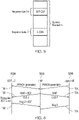
- Figure 5 represents a first common search space (L-CSS) for a RAR scheduling control message for a legacy device configured within frequency band A and a second common search space (EDT-CSS) for a RAR scheduling control message for an EDT-capable device configured within frequency band B, wherein frequency band A and frequency band B are at different frequencies within the overall system frequency bandwidth.
- L-CSS first common search space
- EDT-CSS second common search space
- an EDT capable UE after transmitting a PRACH preamble (e.g. in a step of the random access process corresponding to step S1 in Figure 2 ), an EDT capable UE will monitor the EDT-CSS for a scheduling message allocating resources for the RAR message transmitted by the base station in response to receiving the PRACH preamble.
- the scheduling message in the EDT-CSS may correspond to an MPDCCH carrying a DCI that schedules the RAR.
- a legacy UE would, after transmitting a PRACH preamble, monitor the L-CSS for a possible DCI that schedules the RAR.
- This approach of separately configured CSSs for EDT and non-EDT terminal devices enables the eNB to provide a separate RAR for an EDT capable UE and a legacy UE, even if they both use the same preamble, and so therefore can provide different UL grants in each of the RARs such that the UEs can be allocated different uplink resources for their respective Message 3s, which can help reduce contention / interference at this stage of their respective random access procedures, and more efficiently allow more resources to be allocated for Message 3 for EDT-capable terminal devices than for legacy terminal devices.
- the eNB can also help reduce contention / interference by allocating resources for only one of the two types of terminal device using only one of the CSS, for example, the eNB might not schedule a legacy UE by only sending a DL grant (scheduling control message) for RAR in the EDT-CSS but not the L-CSS.
- Figure 6 is a ladder diagram schematically showing steps of first and second random access procedures respectively undertaken by the legacy terminal device 506 (right-hand node in Figure 6 ), the EDT-capable terminal device 508 (left-hand node in Figure 6 ), and the base station 504 (centre node in Figure 6 ) represented in Figure 4 in accordance with certain embodiments of the disclosure.
- aspects of this operation which are not specifically described herein, for example the particular signalling protocols adopted, may be implemented in accordance with conventional techniques for communicating in wireless telecommunications systems.
- the process of Figure 6 for each terminal device is closely based on the process represented in Figure 2 , and aspects of Figure 6 which correspond with aspects of Figure 2 are not discussed in detail in the interests of brevity.
- the base station has previously configured a first CSS (CSS-1) for legacy terminal devices (or EDT-capable terminal devices when not requesting for EDT) to use for receiving a scheduling message for RAR and a second, different, CSS (CSS-2) for EDT-capable terminal devices to use for receiving a scheduling message for RAR in accordance with the principles discussed above.
- the manner in which the individual CSSs are selected may be in accordance with conventional techniques for establishing a CSS to use for receiving a scheduling message for RAR, albeit in accordance with embodiments of the disclosure this is done twice to provide respective CSSs for the two types of terminal device.
- the indication of the respective CSSs may be communicated to the terminal devices in various ways, for example in system information signalling, e.g. SIB (system information block) signalling in an LTE-context and / or in prior UE-specific RRC signalling.
- SIB system information block
- both the legacy terminal device 506 and the EDT-capable terminal device determine, by coincidence, they should initiate a random access procedure at around the same time. This may be, for example, because the legacy terminal device wishes to transition to an RRC connected mode to uplink data (i.e. transmit uplink data to the base station) and the EDT-capable terminal wishes to uplink data (i.e. transmit uplink data to the base station) in an EDT approach (i.e. as part of a random access procedure as discussed above). It will be appreciated the specific reasons why the terminal devices have data to uplink and the information content of the data are not significant to the principles described herein.
- the legacy terminal device 506 and the EDT-capable terminal device 508 each transmit a PRACH preamble to the base station 504, and in this example scenario are assumed to have selected the same PRACH preamble (e.g. one of the preambles in the EDT set in Figure 3 ) and the same transmission resources to do this.
- the base station On detecting a terminal device has transmitted a preamble from the EDT set of preambles it is assumed here the base station decides it will allow the use of EDT (if it is needed - at this stage the base station does not know if a received PRACH preamble has come from an EDT-capable UE). This determination may be based on the extent to which the base station currently has sufficient resources available to support EDT, for example having regard to conventional scheduling decision processes in wireless telecommunications systems. It may be noted that in general the base station will typically not be aware that more than one UE has sent the same preamble.
- the base station transmits a first RAR response that is scheduled using the first (legacy) CSS (CSS-1), as indicted in Figure 6 in step T2A and transmits a second RAR response that is scheduled using the second (legacy) CSS (CSS-2), as indicted in Figure 6 in step T2B.
- the second RAR response of step T2B indicates EDT is available (e.g. based on setting an EDT flag using one of the reserved bits in the RAR as discussed above).
- the legacy UE 506 searches for a scheduling message for a response to its random access request message of step T1A using CSS-1, and receives this in step T2A whereas the EDT-capable UE 508 searches for a scheduling message for a response to its random access request message of step T1B using CSS-2, and receives this in step T2B.
- the contents of the RAR message scheduled using CSS-1 and the RAR message scheduled using CSS-2 can be different (because they can be scheduled for different resources).
- the first RAR received by the legacy device 506 in step T2A may allocate uplink resources for Message 3 for the legacy device 506 in the usual way, and the legacy device 506 may transmit its Message 3 accordingly, as indicated in Figure 6 in step T3A.
- the second RAR received by the EDT-capable terminal device 508 in step T2B may allocate uplink resources for Message 3 for the EDT-capable terminal device 506 which are different from those allocated to the legacy device.
- the allocation of resources identified in the RAR scheduled using CSS-2 may thus allow for EDT data to be included with Message 3, in accordance with proposed approaches for EDT, and the EDT-capable device 508 may accordingly transmit its Message 3 with EDT data as indicated in Figure 6 in step T3B.
- the respective terminal devices may continue in accordance with known approaches.
- the legacy device 506 may continue to complete the RRC connection procedure while the EDT-capable device, having sent its EDT data in step T3B may return to its previous state.
- an EDT-capable UE may decide to adopt the legacy RACH procedure (i.e. search the CSS configured for legacy devices and transmit Message 3 on the resources allocated by the RAR scheduled using the legacy CSS), for example when it does not wish to use EDT but wishes to establish a conventional RRC connection, e.g. to exchange a greater amount of data than EDT supports.
- the said different CSSs may be those used to schedule a retransmission for Message 3.
- the different CSSs can be configured in different frequency and/or time resources. This approach recognizes that the CSS scheduling the RAR and the CSS scheduling the retransmission for Message 3 may be configured separately (i.e. they can be different) and if a collision occurs for an initial Message 3 transmission for two terminal devices, the respective Message 3s are likely to be received at a poor SINR (signal to interference plus noise ratio) due to interference from the colliding UE, and so a retransmission may be more likely to be required.
- SINR signal to interference plus noise ratio
- Configuring different CSSs for EDT-capable and legacy UEs can allow the eNB to schedule different resources for the Message 3 retransmission for each type of UE, therefore helping avoid a scenario in which retransmissions of Message 3 for legacy and EDT-capable terminal devices continue to interfere with each other.
- a common search space for scheduling RAR for EDT-capable terminal devices may be different from a common search space for scheduling a retransmission of Message 3 for EDT-capable terminal devices.
- the common search space for scheduling RAR for EDT-capable terminal devices may in some cases be the same as the common search space for scheduling RAR for legacy (non-EDT) terminal devices.
- EDT-capable UEs and legacy UEs may share the same CSS for RAR but the CSS configured for control messages scheduling Message 3 retransmissions for EDT-capable UEs and legacy UEs may be different.
- This approach recognizes that if a preamble collision between an EDT-capable UE and a legacy UE occurs (i.e. both UEs transmit the same PRACH preamble at the same time), using the same CSS to schedule the RAR for both types of UE would result in the eNB receiving two types of Message 3, i.e. a first Message 3 from the legacy terminal device and a second Message 3 from the EDT-capable terminal device.
- an eNB may be able to decode one of the message 3s, and with signal processing, e.g. cancellation to remove the contribution of the decoded message 3 from the signal, determine there was another message 3 that it cannot decode properly (e.g. due to poor SNR caused by interference).
- the base station can request retransmission for the message 3 it could not decode from its initial transmission.
- the base station may be unable to decode any message 3 (e.g.
- Figure 7 is a ladder diagram schematically showing steps of first and second random access procedures respectively undertaken by the legacy terminal device 506 (right-hand node in Figure 7 ), the EDT-capable terminal device 508 (left-hand node in Figure 7 ), and the base station 504 (centre node in Figure 7 ) represented in Figure 3 in accordance with certain embodiments of the disclosure.
- Various aspects of Figure 7 are similar to, and will be understood from, corresponding aspects of Figure 6 .
- aspects of this operation which are not specifically described herein, for example the particular signalling protocols adopted, may be implemented in accordance with conventional techniques for communicating in wireless telecommunications systems.
- the process of Figure 7 for each terminal device is closely based on the process represented in Figure 2 , and aspects of Figure 7 which correspond with aspects of Figure 2 are not discussed in detail in the interests of brevity.
- both the legacy terminal device 506 and the EDT-capable terminal device 508 determine, by coincidence, they should initiate a random access procedure at around the same time.
- the legacy terminal device 506 and the EDT-capable terminal device 508 each transmit a PRACH preamble to the base station 504, and in this example scenario are again assumed to have selected the same PRACH preamble (e.g. one of the preambles in the EDT set in Figure 3 ) and transmission resources to do this.
- the base station On detecting a terminal device has transmitted a preamble from the EDT set of preambles it is assumed here the base station decides it will allow the use of EDT. This determination may be based on the extent to which the base station currently has sufficient resources available to support EDT, for example having regard to conventional scheduling decision processes in wireless telecommunications systems.
- the base station transmits a RAR response which indicates EDT is available (e.g. based on setting an EDT flag using one of the reserved bits in the RAR as discussed above).
- the same common search space (CSS-0) is used for the control message scheduling the RAR for both types of UE.
- both UEs receive the same RAR message (with the EDT indicator set) which indicates the same uplink resources for Message 3, as schematically indicated in Figure 7 in steps U2A and U2B (i.e. steps U2A and U2B represent the two different UEs receiving the same message from the base station).
- the EDT UE On receiving the RAR in step U2B the EDT UE identifies from the EDT flag the RAR is allocating resources for EDT in Message 3 and responds by transmitting its Message 3 with the EDT data in step U3B. This may be performed generally in accordance with proposed techniques for EDT.
- the legacy UE does not recognise (i.e. it ignores) the EDT flag and interprets the RAR as allocating resources for Message 3 in the usual way and responds by transmitting its conventional (i.e. non-EDT) Message 3 in step U3A in accordance with conventional techniques.
- the base station blind decodes for both Message 3 formats and is assumed here to successfully receive the Message 3 (including EDT data) from the EDT capable UE 508.
- the EDT-capable device having sent its EDT data in step U3B may return to its previous state, potentially after receiving appropriate acknowledgment signalling for its Message 3.
- the eNB is able to recognize that there was also a Message 3 transmitted by a legacy terminal device (e.g. from its decoding process). For example, the eNB could perform successive interference cancellation techniques in order to subtract a correctly received EDT Msg3 from the composite received signal, leaving a residual signal that only comprises the legacy Msg3. Based on a characteristic of the residual signal, such as the frequency span of the residual signal, the eNB may thus determine that a legacy Msg3 had also been transmitted. In another example, the eNB may analyse received reference signals and determine that a received power in the reference signals is greater for a time or frequency duration that aligns with a legacy Msg3 colliding with an EDT Msg3, and thereby detect there has been a collision).
- the eNB 504 transmits HARQ feedback requesting a retransmission of the legacy Message 3, as indicated in Figure 7 in step U4A.
- the scheduling message allocating the uplink resources for the retransmission of the Message 3 for legacy terminal devices uses a common search space (e.g. CSS-1) which is configured for the legacy UEs but not configured for the EDT-capable UEs because they are instead configured to use a different common search space (e.g. CSS-2) to seek scheduling messages for a retransmission of Message 3.
- the different CSSs for scheduling Message 3 transmissions for each type of UE may be established and communicated to the UEs using the same principles as discussed above in relation to Figure 6 (e.g.
- the legacy UE receives the control message scheduling the Message 3 retransmission, and responds by retransmitting its Message 3 in step U5A, the EDT-capable UE does not receive the control message scheduling a Message 3 retransmission (because it is not searching the corresponding CSS). Thus the legacy UE is able to retransmit its Message 3 without interference from the EDT-capable UE.
- the legacy device 506 may then continue to complete the RRC connection procedure in the usual way.
- Figure 8 is similar to and will be understood from Figure 7 but represents a scenario in which the eNB requests a retransmission of Message 3 from both the EDT-capable UE and the legacy UE.
- Steps V1A, V1B, V2A, V2B, V3A, V3B, V4A and V5A in Figure 8 are similar to, and will be understood from, the corresponding steps U1A, U1B, U2A, U2B, U3A, U3B, U4A and U5A in Figure 7 .
- the EDT-capable UE 508 and the legacy UE 506 transmit the same preamble (steps V1A and V1B) and the eNB 504 responds to both UEs with a RAR scheduled on a common search space (e.g. CSS-0) configured for RAR scheduling for both types of UE with the relevant indicator set to indicate to the EDT-capable UE that EDT is to be scheduled (steps V2A and V2B).
- Both types of UE transmit their Message 3, where the EDT capable UE also transmits uplink data with its Message 3 as in Figure 7 (steps V3A and V3B).
- the eNB fails to detect either of the Message 3 transmissions, and so sends a HARQ feedback request for Message 3 retransmission for both types of UEs (steps V4A and V4B).
- the scheduling message allocating the uplink resources for the retransmission of the Message 3 for legacy terminal devices uses a first common search space (e.g. CSS-1) whereas the scheduling message allocating the uplink resources for the retransmission of the Message 3 for EDT-capable terminal devices uses a second common search space (e.g. CSS-2).
- the different CSSs for scheduling Message 3 transmissions for each type of UE may be established and communicated to the UEs using the same principles as discussed above in relation to Figure 6 (e.g. using SIB and / or prior UE-specific RRC signalling). Because the eNB has established the different CSSs for scheduling retransmissions of Message 3 for the different terminal devices the eNB is able to allocate different uplink resources for the Message 3 retransmissions to help avoid interference between the retransmissions from the different types of terminal device (as schematically indicted in Figure 8 in steps V5A ad V5B).
- the RAR received by the EDT-capable UE in step V2B may include an indication of whether the EDT capable UE should use CSS-2 or CSS-1 for searching for downlink control information scheduling a Message 3 retransmission.
- This approach provides the eNB with flexibility to decide which CSS to use. For example, if the eNB decides not to enable EDT for an EDT capable UE (e.g. due to limitations on available resources) it can instruct the UE to monitor the CSS-1 (the CSS configured for legacy UEs) rather than CSS-2 (the CSS configured for EDT-capable UEs).
- This indication could be implicitly signalled to the UE, for example an EDT-capable UE receiving a RAR that indicates EDT is not allowed (such that the UE needs to RRC connect to uplink its data) may take this to implicitly indicate it should monitor the CSS configured for legacy devices for scheduling Message 3 retransmissions.
- the configuration of the EDT-CSS is RRC configured.
- This embodiment does not mean that the EDT-CSS configuration cannot also be signalled in the SIB.
- the UE specific RRC configuration overwrites the configuration signalled in the SIB.
- This is useful for non-contention based RACH where the eNB knew the UE that is performing the RACH e.g. due to a PDCCH order.
- An implementation of this is where the non-contention based RACH, which is explicitly signalled by the eNB using a DCI, uses the RRC configured EDT-CSS whilst contention based RACH uses the SIB signalled EDT-CSS configurations.
- a method of operating a base station in a wireless telecommunications system to support a first random access procedure for a first terminal device of a first type and a second random access procedure for a second terminal device of a second type, wherein a message size / amount of data for an uplink message of the second random access procedure is greater than a message size / amount of data for a corresponding uplink message of the first random access procedure
- the method comprises: establishing / configuring a first common search space for use with the first random access procedure; establishing / configuring a second common search space for use with the second random access procedure; exchanging a first series of random access procedure messages with the first terminal device, wherein a first scheduling message indicating radio resources for at least one of the first series of random access procedure messages is transmitted by the base station to the first terminal device on radio resources in the first common search space, and exchanging a second series of random access procedure messages with the second terminal device, wherein a second scheduling message indicating radio resources for at least one of
- a message of a random access procedure including EDT data may in some cases have a message size which is larger than the message size of a corresponding message in a random access procedure that does not include EDT data, this is not always the case.
- the EDT random access procedure message containing the additional data may have the same message size as the corresponding legacy (non-EDT) random access procedure message, but a different coding scheme.
- predetermined / predefined information may in general be established, for example, by definition in an operating standard for the wireless telecommunication system, or in previously exchanged signalling between the base station and terminal devices, for example in system information signalling, or in association with radio resource control setup signalling, or in information stored on a SIM card. That is to say, the specific manner in which the relevant predefined information is established and shared between the various elements of the wireless telecommunications system is not of primary significance to the principles of operation described herein.
Landscapes
- Engineering & Computer Science (AREA)
- Computer Networks & Wireless Communication (AREA)
- Signal Processing (AREA)
- Computer Security & Cryptography (AREA)
- Mobile Radio Communication Systems (AREA)
Claims (15)
- Procédé de fonctionnement d'un équipement d'infrastructure de réseau (504) dans un système de télécommunication sans fil (500) pour prendre en charge une première procédure d'accès aléatoire pour un premier dispositif terminal (506) et une seconde procédure d'accès aléatoire pour un second dispositif terminal (508), où une quantité de données pour un message de liaison montante de la seconde procédure d'accès aléatoire est supérieure à une quantité de données pour un message de liaison montante correspondant de la première procédure d'accès aléatoire, et où le procédé comprend les étapes suivantes :établir un premier espace de recherche commun à utiliser avec la première procédure d'accès aléatoire ;établir un second espace de recherche commun à utiliser avec la seconde procédure d'accès aléatoire ;échanger une première série de messages de procédure d'accès aléatoire avec le premier dispositif terminal, où un premier message de planification indiquant des ressources radio pour au moins un message de la première série de messages de procédure d'accès aléatoire est transmis par l'équipement d'infrastructure de réseau au premier dispositif terminal en utilisant des ressources radio dans le premier espace de recherche commun, etéchanger une seconde série de messages de procédure d'accès aléatoire avec le second dispositif terminal, où un second message de planification indiquant des ressources radio pour au moins un message de la seconde série de messages de procédure d'accès aléatoire est transmis par l'équipement d'infrastructure de réseau au second dispositif terminal en utilisant des ressources radio dans le second espace de recherche commun.
- Procédé selon la revendication 1, dans lequel le premier espace de recherche commun comprend un premier ensemble de ressources de fréquences et le second espace de recherche commun comprend un second ensemble de ressources de fréquences qui est différent du premier ensemble de ressources de fréquences.
- Procédé selon la revendication 1, dans lequel le premier espace de recherche commun comprend un premier ensemble de ressources temporelles et le second espace de recherche commun comprend un second ensemble de ressources temporelles qui est différent du premier ensemble de ressources temporelles.
- Procédé selon la revendication 1, dans lequel :la première série de messages de procédure d'accès aléatoire comprend un premier message de demande d'accès aléatoire reçu par l'équipement d'infrastructure de réseau en provenance du premier dispositif terminal, un premier message de réponse d'accès aléatoire transmis par l'équipement d'infrastructure de réseau au premier dispositif terminal en réponse à la réception du premier message de demande d'accès aléatoire, et un premier message trois reçu par l'équipement d'infrastructure de réseau en provenance du premier dispositif terminal en utilisant des ressources radio allouées dans le premier message de réponse d'accès aléatoire ; etla seconde série de messages de procédure d'accès aléatoire comprend un second message de demande d'accès aléatoire reçu par l'équipement d'infrastructure de réseau en provenance du second dispositif terminal, un second message de réponse d'accès aléatoire transmis par l'équipement d'infrastructure de réseau au second dispositif terminal en réponse à la réception du second message de demande d'accès aléatoire, et un second message trois reçu par l'équipement d'infrastructure de réseau en provenance du dispositif terminal en utilisant des ressources radio allouées par le second message de réponse d'accès aléatoire.
- Procédé selon la revendication 4, dans lequel le second message trois est le message de liaison montante de la seconde procédure d'accès aléatoire ayant une quantité de données supérieure à la quantité de données pour le message de liaison montante correspondant de la première procédure d'accès aléatoire, le message de liaison montante correspondant de la première procédure d'accès aléatoire étant le premier message trois.
- Procédé selon la revendication 4, dans lequel :le premier message de planification transmis par l'équipement d'infrastructure de réseau au premier dispositif terminal en utilisant des ressources radio dans le premier espace de recherche commun indique des ressources radio pour le premier message de réponse d'accès aléatoire ; etle second message de planification transmis par l'équipement d'infrastructure de réseau au second dispositif terminal en utilisant des ressources radio dans le second espace de recherche commun indique des ressources radio pour le second message de réponse d'accès aléatoire.
- Procédé selon la revendication 4, dans lequel :le premier message de planification transmis par l'équipement d'infrastructure de réseau au premier dispositif terminal en utilisant des ressources radio dans le premier espace de recherche commun indique des ressources radio pour une retransmission du premier message trois ; etle second message de planification transmis par l'équipement d'infrastructure de réseau au second dispositif terminal en utilisant des ressources radio dans le second espace de recherche commun indique des ressources radio pour une retransmission du second message trois.
- Procédé selon la revendication 7, dans lequel un message de planification transmis par l'équipement d'infrastructure de réseau au premier dispositif terminal pour le premier message de réponse d'accès aléatoire et un message de planification transmis par l'équipement d'infrastructure de réseau au second dispositif terminal pour le second message de réponse d'accès aléatoire sont transmis par l'équipement d'infrastructure de réseau aux dispositifs terminaux respectifs en utilisant des ressources radio dans le même espace de recherche commun.
- Procédé selon la revendication 4, dans lequel le second message de réponse d'accès aléatoire comprend une indication que le second message de réponse d'accès aléatoire est associé à la seconde procédure d'accès aléatoire.
- Procédé selon la revendication 4, dans lequel le second message de réponse d'accès aléatoire comprend une indication du fait que le second dispositif terminal doit rechercher un message de planification ultérieur dans le premier espace de recherche commun ou le second espace de recherche commun.
- Équipement d'infrastructure de réseau (504) destiné à être utilisé dans un système de télécommunication sans fil (500) pour prendre en charge une première procédure d'accès aléatoire pour un premier dispositif terminal (506) et une seconde procédure d'accès aléatoire pour un second dispositif terminal (508), où une quantité de données pour un message de liaison montante de la seconde procédure d'accès aléatoire est supérieure à une quantité de données pour un message de liaison montante correspondant de la première procédure d'accès aléatoire, où l'équipement d'infrastructure de réseau comprend des circuits de contrôleur (504b) et des circuits d'émetteur-récepteur (504a) configurés de telle sorte que l'équipement d'infrastructure de réseau puisse fonctionner pour :établir un premier espace de recherche commun à utiliser avec la première procédure d'accès aléatoire ;établir un second espace de recherche commun à utiliser avec la seconde procédure d'accès aléatoire ;échanger une première série de messages de procédure d'accès aléatoire avec le premier dispositif terminal, où au moins un message de la première série de messages de procédure d'accès aléatoire est transmis en utilisant des ressources radio indiquées par un premier message de planification transmis par l'équipement d'infrastructure de réseau au premier dispositif terminal en utilisant des ressources radio dans le premier espace de recherche commun, etéchanger une seconde série de messages de procédure d'accès aléatoire avec le second dispositif terminal, où au moins un message de la seconde série de messages de procédure d'accès aléatoire est transmis en utilisant des ressources radio indiquées par un second message de planification transmis par l'équipement d'infrastructure de réseau au second dispositif terminal en utilisant des ressources radio dans le second espace de recherche commun.
- Circuits intégrés pour un équipement d'infrastructure de réseau (504) destiné à être utilisé dans un système de télécommunication sans fil (500) pour prendre en charge une première procédure d'accès aléatoire pour un premier dispositif terminal (506) et une seconde procédure d'accès aléatoire pour un second dispositif terminal (508), où une quantité de données pour un message de liaison montante de la seconde procédure d'accès aléatoire est supérieure à une quantité de données pour un message de liaison montante correspondant de la première procédure d'accès aléatoire, où les circuits intégrés comprennent des circuits de contrôleur (504b) et des circuits d'émetteur-récepteur (504a) configurés pour fonctionner ensemble de telle sorte que l'équipement d'infrastructure de réseau puisse fonctionner pour :établir un premier espace de recherche commun à utiliser avec la première procédure d'accès aléatoire ;établir un second espace de recherche commun à utiliser avec la seconde procédure d'accès aléatoire ;échanger une première série de messages de procédure d'accès aléatoire avec le premier dispositif terminal, où au moins un message de la première série de messages de procédure d'accès aléatoire est transmis en utilisant des ressources radio indiquées par un premier message de planification transmis par l'équipement d'infrastructure de réseau au premier dispositif terminal en utilisant des ressources radio dans le premier espace de recherche commun, etéchanger une seconde série de messages de procédure d'accès aléatoire avec le second dispositif terminal, où au moins un message de la seconde série de messages de procédure d'accès aléatoire est transmis en utilisant des ressources radio indiquées par un second message de planification transmis par l'équipement d'infrastructure de réseau au second dispositif terminal en utilisant des ressources radio dans le second espace de recherche commun.
- Procédé de fonctionnement d'un dispositif terminal (508) dans un système de télécommunication sans fil (500), dans lequel un équipement d'infrastructure de réseau (504) prend en charge des première et seconde procédures d'accès aléatoire pour le dispositif terminal, où une quantité de données pour un message de liaison montante de la seconde procédure d'accès aléatoire est supérieure à une quantité de données pour un message de liaison montante correspondant de la première procédure d'accès aléatoire, et où le procédé comprend les étapes suivantes :déterminer que le dispositif terminal doit mettre en œuvre une procédure d'accès aléatoire ;sélectionner s'il faut suivre la première procédure d'accès aléatoire ou la seconde procédure d'accès aléatoire selon que le dispositif terminal a l'intention d'utiliser la plus grande quantité de données pour la seconde procédure d'accès aléatoire ;déterminer un espace de recherche commun à utiliser pour recevoir un message de planification indiquant des ressources radio pour un message de procédure d'accès aléatoire transmis par l'équipement d'infrastructure de réseau selon que le dispositif terminal a choisi de suivre la première procédure d'accès aléatoire ou la seconde procédure d'accès aléatoire ; etsurveiller le message de planification en utilisant l'espace de recherche commun sélectionné.
- Dispositif terminal (508) destiné à être utilisé dans un système de télécommunication sans fil (500), dans lequel un équipement d'infrastructure de réseau (504) prend en charge des première et seconde procédures d'accès aléatoire pour le dispositif terminal, où une quantité de données pour un message de liaison montante de la seconde procédure d'accès aléatoire est supérieure à une quantité de données pour un message de liaison montante correspondant de la première procédure d'accès aléatoire, où le dispositif terminal comprend des circuits de contrôleur (508b) et des circuits d'émetteur-récepteur (508a) configurés de telle sorte que le dispositif de terminal puisse fonctionner pour :déterminer que le dispositif terminal doit mettre en œuvre une procédure d'accès aléatoire ;sélectionner s'il faut suivre la première procédure d'accès aléatoire ou la seconde procédure d'accès aléatoire selon que le dispositif terminal a l'intention d'utiliser la plus grande quantité de données pour la seconde procédure d'accès aléatoire ;déterminer un espace de recherche commun à utiliser pour recevoir un message de planification indiquant des ressources radio pour un message de procédure d'accès aléatoire transmis par l'équipement d'infrastructure de réseau selon que le dispositif terminal a choisi de suivre la première procédure d'accès aléatoire ou la seconde procédure d'accès aléatoire ; etsurveiller le message de planification en utilisant l'espace de recherche commun sélectionné.
- Circuits intégrés pour un dispositif terminal (508) destiné à être utilisé dans un système de télécommunication sans fil (500), dans lequel un équipement d'infrastructure de réseau (504) prend en charge des première et seconde procédures d'accès aléatoire pour le dispositif terminal, où une quantité de données pour un message de liaison montante de la seconde procédure d'accès aléatoire est supérieure à une quantité de données pour un message de liaison montante correspondant de la première procédure d'accès aléatoire, où le circuit comprend un circuit de contrôleur (508b) et un circuit d'émetteur-récepteur (508a) configurés de telle sorte que le dispositif terminal puisse fonctionner pour :déterminer que le dispositif terminal doit mettre en œuvre une procédure d'accès aléatoire ;sélectionner s'il faut suivre la première procédure d'accès aléatoire ou la seconde procédure d'accès aléatoire selon que le dispositif terminal a l'intention d'utiliser la plus grande quantité de données pour la seconde procédure d'accès aléatoire ;déterminer un espace de recherche commun à utiliser pour recevoir un message de planification indiquant des ressources radio pour un message de procédure d'accès aléatoire transmis par l'équipement d'infrastructure de réseau selon que le dispositif terminal a choisi de suivre la première procédure d'accès aléatoire ou la seconde procédure d'accès aléatoire ; etsurveiller le message de planification en utilisant l'espace de recherche commun sélectionné.
Applications Claiming Priority (2)
| Application Number | Priority Date | Filing Date | Title |
|---|---|---|---|
| EP18154993 | 2018-02-02 | ||
| PCT/EP2019/052514 WO2019149894A1 (fr) | 2018-02-02 | 2019-02-01 | Appareil et procédés de télécommunications |
Publications (2)
| Publication Number | Publication Date |
|---|---|
| EP3747227A1 EP3747227A1 (fr) | 2020-12-09 |
| EP3747227B1 true EP3747227B1 (fr) | 2022-03-30 |
Family
ID=61157134
Family Applications (1)
| Application Number | Title | Priority Date | Filing Date |
|---|---|---|---|
| EP19701685.0A Active EP3747227B1 (fr) | 2018-02-02 | 2019-02-01 | Procédé de fonctionnement d'un équipement d'infrastructure de réseau, procédé correspondant de fonctionnement d'un dispositif terminal, appareils correspondants et circuits intégrés |
Country Status (3)
| Country | Link |
|---|---|
| US (2) | US11570819B2 (fr) |
| EP (1) | EP3747227B1 (fr) |
| WO (1) | WO2019149894A1 (fr) |
Families Citing this family (11)
| Publication number | Priority date | Publication date | Assignee | Title |
|---|---|---|---|---|
| EP3747227B1 (fr) * | 2018-02-02 | 2022-03-30 | Sony Group Corporation | Procédé de fonctionnement d'un équipement d'infrastructure de réseau, procédé correspondant de fonctionnement d'un dispositif terminal, appareils correspondants et circuits intégrés |
| US20190208411A1 (en) * | 2018-03-16 | 2019-07-04 | Intel Corporation | Security framework for msg3 and msg4 in early data transmission |
| CN111886817B (zh) * | 2018-04-04 | 2021-12-10 | 华为技术有限公司 | 数据传输方法、通信设备及网络设备 |
| EP3834560B1 (fr) * | 2018-08-09 | 2023-07-05 | Telefonaktiebolaget Lm Ericsson (Publ) | Rapport de qualité de canal dans lte-m |
| EP4088541A4 (fr) * | 2020-01-09 | 2023-12-20 | Telefonaktiebolaget LM Ericsson (publ) | Accès aléatoire pour équipement utilisateur de faible complexité |
| US11812477B2 (en) * | 2020-05-06 | 2023-11-07 | Samsung Electronics Co., Ltd. | Methods and apparatus for random access with contention resolution message repetition |
| JP2023539223A (ja) * | 2020-08-28 | 2023-09-13 | コーニンクレッカ フィリップス エヌ ヴェ | Ueカバレッジの拡張 |
| CN116830653A (zh) * | 2020-09-24 | 2023-09-29 | 欧芬诺有限责任公司 | 小数据传输程序中的释放消息 |
| EP4229888A4 (fr) * | 2020-10-16 | 2024-06-05 | JRD Communication (Shenzhen) Ltd | Équipement utilisateur, station de base et procédé d'identification d'équipement utilisateur |
| EP4233424A1 (fr) * | 2020-10-22 | 2023-08-30 | Telefonaktiebolaget LM Ericsson (publ) | Noeud de réseau radio, ue et procédé exécuté en son sein |
| WO2023076102A1 (fr) * | 2021-10-27 | 2023-05-04 | Kyocera Corporation | Schéma d'accès aléatoire basé sur un accès par intervalles codés |
Family Cites Families (14)
| Publication number | Priority date | Publication date | Assignee | Title |
|---|---|---|---|---|
| US10165423B2 (en) * | 2015-07-10 | 2018-12-25 | Qualcomm Incorporated | Common search space for machine type communications |
| EP3471457B1 (fr) * | 2017-04-28 | 2021-03-10 | LG Electronics Inc. -1- | Procédé de transmission de données basé sur une transmission edt |
| CN110235513B (zh) * | 2017-07-27 | 2023-05-09 | Lg电子株式会社 | 用于执行edt的方法和装置 |
| US10779333B2 (en) * | 2017-09-28 | 2020-09-15 | Apple Inc. | Early data transmission in wireless communication system |
| WO2019064260A1 (fr) * | 2017-09-29 | 2019-04-04 | Telefonaktiebolaget Lm Ericsson (Publ) | Systèmes et procédés fournissant une solution de transmission de données précoce en veille permettant un mode d'économie d'énergie |
| US11382137B2 (en) * | 2017-10-10 | 2022-07-05 | Telefonaktiebolaget Lm Ericsson (Publ) | Mobile-terminated early data transmission |
| US11039477B2 (en) * | 2017-11-17 | 2021-06-15 | Mediatek Inc. | NB-IoT PRACH resource partitioning and multiple grants in RAR for EDT |
| EP3718368A4 (fr) * | 2017-11-28 | 2021-07-21 | Nokia Technologies Oy | Transmission de données précoces |
| CN110012557A (zh) * | 2018-01-05 | 2019-07-12 | 夏普株式会社 | 无线通信设备和方法 |
| CN110062474B (zh) * | 2018-01-19 | 2024-05-10 | 夏普株式会社 | 用户设备、基站和相关方法 |
| EP3747227B1 (fr) * | 2018-02-02 | 2022-03-30 | Sony Group Corporation | Procédé de fonctionnement d'un équipement d'infrastructure de réseau, procédé correspondant de fonctionnement d'un dispositif terminal, appareils correspondants et circuits intégrés |
| US11533760B2 (en) * | 2018-05-11 | 2022-12-20 | Sony Corporation | Method and device for communicating with a selected transport block size |
| EP3834573B1 (fr) * | 2018-08-09 | 2023-12-20 | Sony Group Corporation | Dispositif de communications, équipement d'infrastructure et procédés |
| US11632806B2 (en) * | 2018-08-10 | 2023-04-18 | Sony Corporation | Communications device, infrastructure equipment and methods |
-
2019
- 2019-02-01 EP EP19701685.0A patent/EP3747227B1/fr active Active
- 2019-02-01 WO PCT/EP2019/052514 patent/WO2019149894A1/fr not_active Ceased
- 2019-02-01 US US16/966,044 patent/US11570819B2/en active Active
-
2022
- 2022-12-30 US US18/148,471 patent/US11864240B2/en active Active
Also Published As
| Publication number | Publication date |
|---|---|
| EP3747227A1 (fr) | 2020-12-09 |
| US20200367294A1 (en) | 2020-11-19 |
| US20230137787A1 (en) | 2023-05-04 |
| WO2019149894A1 (fr) | 2019-08-08 |
| US11570819B2 (en) | 2023-01-31 |
| US11864240B2 (en) | 2024-01-02 |
Similar Documents
| Publication | Publication Date | Title |
|---|---|---|
| US11864240B2 (en) | Telecommunications apparatus and methods | |
| US10701677B2 (en) | Method and apparatus for uplink resource assignment for cellular network using unlicensed bands | |
| US11917659B2 (en) | Telecommunications apparatus and methods including selecting a TBS based on an indicated maximum TBS | |
| US11277858B2 (en) | Uplink transmission scheme | |
| US11743885B2 (en) | Telecommunications apparatus and methods using a common scheduling message for different random access procedures | |
| US11864207B2 (en) | Method and device for transmitting or receiving physical sidelink feedback channel in wireless communication system | |
| US20230137259A1 (en) | Method for transmitting and receiving inter-ue coordination information in a wireless communication system and apparatus therefor | |
| CN112822778B (zh) | 用于侧行链路传送的方法及用户设备 | |
| KR20160114606A (ko) | 통신 디바이스 및 방법 | |
| EP3925338B1 (fr) | Dispositif de communication, équipement d'infrastructure et procédés | |
| CN114424487B (zh) | 通信装置、基础设施设备和方法 | |
| US12245289B2 (en) | Communications device, infrastructure equipment and methods for differentiating between 2-step RACH and 4-step RACH | |
| US11337256B2 (en) | Methods, infrastructure equipment and communications device | |
| CN114451058A (zh) | 用于随机接入过程的方法和装置 | |
| KR20220160590A (ko) | 멀티미디어 우선 순위 및 미션 크리티컬 서비스들에 대한 랜덤 액세스의 우선 순위를 지정하는 방법 및 그 장치 | |
| EP3834573B1 (fr) | Dispositif de communications, équipement d'infrastructure et procédés | |
| US10142922B2 (en) | D2D peer discovery and data transmission | |
| EP4094526B1 (fr) | Dispositif de communication, équipement d'infrastructure et procédés de gestion de collisions de liaison montante |
Legal Events
| Date | Code | Title | Description |
|---|---|---|---|
| STAA | Information on the status of an ep patent application or granted ep patent |
Free format text: STATUS: UNKNOWN |
|
| STAA | Information on the status of an ep patent application or granted ep patent |
Free format text: STATUS: THE INTERNATIONAL PUBLICATION HAS BEEN MADE |
|
| PUAI | Public reference made under article 153(3) epc to a published international application that has entered the european phase |
Free format text: ORIGINAL CODE: 0009012 |
|
| STAA | Information on the status of an ep patent application or granted ep patent |
Free format text: STATUS: REQUEST FOR EXAMINATION WAS MADE |
|
| 17P | Request for examination filed |
Effective date: 20200721 |
|
| AK | Designated contracting states |
Kind code of ref document: A1 Designated state(s): AL AT BE BG CH CY CZ DE DK EE ES FI FR GB GR HR HU IE IS IT LI LT LU LV MC MK MT NL NO PL PT RO RS SE SI SK SM TR |
|
| AX | Request for extension of the european patent |
Extension state: BA ME |
|
| DAV | Request for validation of the european patent (deleted) | ||
| DAX | Request for extension of the european patent (deleted) | ||
| RAP3 | Party data changed (applicant data changed or rights of an application transferred) |
Owner name: SONY GROUP CORPORATION Owner name: SONY EUROPE LIMITED |
|
| GRAP | Despatch of communication of intention to grant a patent |
Free format text: ORIGINAL CODE: EPIDOSNIGR1 |
|
| STAA | Information on the status of an ep patent application or granted ep patent |
Free format text: STATUS: GRANT OF PATENT IS INTENDED |
|
| INTG | Intention to grant announced |
Effective date: 20210902 |
|
| RIN1 | Information on inventor provided before grant (corrected) |
Inventor name: BEALE, MARTIN WARWICK Inventor name: WONG, SHIN HORNG |
|
| GRAS | Grant fee paid |
Free format text: ORIGINAL CODE: EPIDOSNIGR3 |
|
| GRAA | (expected) grant |
Free format text: ORIGINAL CODE: 0009210 |
|
| STAA | Information on the status of an ep patent application or granted ep patent |
Free format text: STATUS: THE PATENT HAS BEEN GRANTED |
|
| AK | Designated contracting states |
Kind code of ref document: B1 Designated state(s): AL AT BE BG CH CY CZ DE DK EE ES FI FR GB GR HR HU IE IS IT LI LT LU LV MC MK MT NL NO PL PT RO RS SE SI SK SM TR |
|
| REG | Reference to a national code |
Ref country code: GB Ref legal event code: FG4D |
|
| REG | Reference to a national code |
Ref country code: CH Ref legal event code: EP |
|
| REG | Reference to a national code |
Ref country code: DE Ref legal event code: R096 Ref document number: 602019013065 Country of ref document: DE |
|
| REG | Reference to a national code |
Ref country code: AT Ref legal event code: REF Ref document number: 1480359 Country of ref document: AT Kind code of ref document: T Effective date: 20220415 |
|
| REG | Reference to a national code |
Ref country code: IE Ref legal event code: FG4D |
|
| REG | Reference to a national code |
Ref country code: LT Ref legal event code: MG9D |
|
| PG25 | Lapsed in a contracting state [announced via postgrant information from national office to epo] |
Ref country code: SE Free format text: LAPSE BECAUSE OF FAILURE TO SUBMIT A TRANSLATION OF THE DESCRIPTION OR TO PAY THE FEE WITHIN THE PRESCRIBED TIME-LIMIT Effective date: 20220330 Ref country code: RS Free format text: LAPSE BECAUSE OF FAILURE TO SUBMIT A TRANSLATION OF THE DESCRIPTION OR TO PAY THE FEE WITHIN THE PRESCRIBED TIME-LIMIT Effective date: 20220330 Ref country code: NO Free format text: LAPSE BECAUSE OF FAILURE TO SUBMIT A TRANSLATION OF THE DESCRIPTION OR TO PAY THE FEE WITHIN THE PRESCRIBED TIME-LIMIT Effective date: 20220630 Ref country code: LT Free format text: LAPSE BECAUSE OF FAILURE TO SUBMIT A TRANSLATION OF THE DESCRIPTION OR TO PAY THE FEE WITHIN THE PRESCRIBED TIME-LIMIT Effective date: 20220330 Ref country code: HR Free format text: LAPSE BECAUSE OF FAILURE TO SUBMIT A TRANSLATION OF THE DESCRIPTION OR TO PAY THE FEE WITHIN THE PRESCRIBED TIME-LIMIT Effective date: 20220330 Ref country code: BG Free format text: LAPSE BECAUSE OF FAILURE TO SUBMIT A TRANSLATION OF THE DESCRIPTION OR TO PAY THE FEE WITHIN THE PRESCRIBED TIME-LIMIT Effective date: 20220630 |
|
| REG | Reference to a national code |
Ref country code: NL Ref legal event code: MP Effective date: 20220330 |
|
| REG | Reference to a national code |
Ref country code: AT Ref legal event code: MK05 Ref document number: 1480359 Country of ref document: AT Kind code of ref document: T Effective date: 20220330 |
|
| PG25 | Lapsed in a contracting state [announced via postgrant information from national office to epo] |
Ref country code: LV Free format text: LAPSE BECAUSE OF FAILURE TO SUBMIT A TRANSLATION OF THE DESCRIPTION OR TO PAY THE FEE WITHIN THE PRESCRIBED TIME-LIMIT Effective date: 20220330 Ref country code: GR Free format text: LAPSE BECAUSE OF FAILURE TO SUBMIT A TRANSLATION OF THE DESCRIPTION OR TO PAY THE FEE WITHIN THE PRESCRIBED TIME-LIMIT Effective date: 20220701 Ref country code: FI Free format text: LAPSE BECAUSE OF FAILURE TO SUBMIT A TRANSLATION OF THE DESCRIPTION OR TO PAY THE FEE WITHIN THE PRESCRIBED TIME-LIMIT Effective date: 20220330 |
|
| PG25 | Lapsed in a contracting state [announced via postgrant information from national office to epo] |
Ref country code: NL Free format text: LAPSE BECAUSE OF FAILURE TO SUBMIT A TRANSLATION OF THE DESCRIPTION OR TO PAY THE FEE WITHIN THE PRESCRIBED TIME-LIMIT Effective date: 20220330 |
|
| PG25 | Lapsed in a contracting state [announced via postgrant information from national office to epo] |
Ref country code: SM Free format text: LAPSE BECAUSE OF FAILURE TO SUBMIT A TRANSLATION OF THE DESCRIPTION OR TO PAY THE FEE WITHIN THE PRESCRIBED TIME-LIMIT Effective date: 20220330 Ref country code: SK Free format text: LAPSE BECAUSE OF FAILURE TO SUBMIT A TRANSLATION OF THE DESCRIPTION OR TO PAY THE FEE WITHIN THE PRESCRIBED TIME-LIMIT Effective date: 20220330 Ref country code: RO Free format text: LAPSE BECAUSE OF FAILURE TO SUBMIT A TRANSLATION OF THE DESCRIPTION OR TO PAY THE FEE WITHIN THE PRESCRIBED TIME-LIMIT Effective date: 20220330 Ref country code: PT Free format text: LAPSE BECAUSE OF FAILURE TO SUBMIT A TRANSLATION OF THE DESCRIPTION OR TO PAY THE FEE WITHIN THE PRESCRIBED TIME-LIMIT Effective date: 20220801 Ref country code: ES Free format text: LAPSE BECAUSE OF FAILURE TO SUBMIT A TRANSLATION OF THE DESCRIPTION OR TO PAY THE FEE WITHIN THE PRESCRIBED TIME-LIMIT Effective date: 20220330 Ref country code: EE Free format text: LAPSE BECAUSE OF FAILURE TO SUBMIT A TRANSLATION OF THE DESCRIPTION OR TO PAY THE FEE WITHIN THE PRESCRIBED TIME-LIMIT Effective date: 20220330 Ref country code: CZ Free format text: LAPSE BECAUSE OF FAILURE TO SUBMIT A TRANSLATION OF THE DESCRIPTION OR TO PAY THE FEE WITHIN THE PRESCRIBED TIME-LIMIT Effective date: 20220330 Ref country code: AT Free format text: LAPSE BECAUSE OF FAILURE TO SUBMIT A TRANSLATION OF THE DESCRIPTION OR TO PAY THE FEE WITHIN THE PRESCRIBED TIME-LIMIT Effective date: 20220330 |
|
| PG25 | Lapsed in a contracting state [announced via postgrant information from national office to epo] |
Ref country code: PL Free format text: LAPSE BECAUSE OF FAILURE TO SUBMIT A TRANSLATION OF THE DESCRIPTION OR TO PAY THE FEE WITHIN THE PRESCRIBED TIME-LIMIT Effective date: 20220330 Ref country code: IS Free format text: LAPSE BECAUSE OF FAILURE TO SUBMIT A TRANSLATION OF THE DESCRIPTION OR TO PAY THE FEE WITHIN THE PRESCRIBED TIME-LIMIT Effective date: 20220730 Ref country code: AL Free format text: LAPSE BECAUSE OF FAILURE TO SUBMIT A TRANSLATION OF THE DESCRIPTION OR TO PAY THE FEE WITHIN THE PRESCRIBED TIME-LIMIT Effective date: 20220330 |
|
| REG | Reference to a national code |
Ref country code: DE Ref legal event code: R097 Ref document number: 602019013065 Country of ref document: DE |
|
| PG25 | Lapsed in a contracting state [announced via postgrant information from national office to epo] |
Ref country code: DK Free format text: LAPSE BECAUSE OF FAILURE TO SUBMIT A TRANSLATION OF THE DESCRIPTION OR TO PAY THE FEE WITHIN THE PRESCRIBED TIME-LIMIT Effective date: 20220330 |
|
| PLBE | No opposition filed within time limit |
Free format text: ORIGINAL CODE: 0009261 |
|
| STAA | Information on the status of an ep patent application or granted ep patent |
Free format text: STATUS: NO OPPOSITION FILED WITHIN TIME LIMIT |
|
| 26N | No opposition filed |
Effective date: 20230103 |
|
| PG25 | Lapsed in a contracting state [announced via postgrant information from national office to epo] |
Ref country code: SI Free format text: LAPSE BECAUSE OF FAILURE TO SUBMIT A TRANSLATION OF THE DESCRIPTION OR TO PAY THE FEE WITHIN THE PRESCRIBED TIME-LIMIT Effective date: 20220330 |
|
| P01 | Opt-out of the competence of the unified patent court (upc) registered |
Effective date: 20230606 |
|
| PG25 | Lapsed in a contracting state [announced via postgrant information from national office to epo] |
Ref country code: IT Free format text: LAPSE BECAUSE OF FAILURE TO SUBMIT A TRANSLATION OF THE DESCRIPTION OR TO PAY THE FEE WITHIN THE PRESCRIBED TIME-LIMIT Effective date: 20220330 |
|
| PG25 | Lapsed in a contracting state [announced via postgrant information from national office to epo] |
Ref country code: MC Free format text: LAPSE BECAUSE OF FAILURE TO SUBMIT A TRANSLATION OF THE DESCRIPTION OR TO PAY THE FEE WITHIN THE PRESCRIBED TIME-LIMIT Effective date: 20220330 |
|
| REG | Reference to a national code |
Ref country code: CH Ref legal event code: PL |
|
| REG | Reference to a national code |
Ref country code: BE Ref legal event code: MM Effective date: 20230228 |
|
| PG25 | Lapsed in a contracting state [announced via postgrant information from national office to epo] |
Ref country code: LU Free format text: LAPSE BECAUSE OF NON-PAYMENT OF DUE FEES Effective date: 20230201 Ref country code: LI Free format text: LAPSE BECAUSE OF NON-PAYMENT OF DUE FEES Effective date: 20230228 Ref country code: CH Free format text: LAPSE BECAUSE OF NON-PAYMENT OF DUE FEES Effective date: 20230228 |
|
| REG | Reference to a national code |
Ref country code: IE Ref legal event code: MM4A |
|
| PG25 | Lapsed in a contracting state [announced via postgrant information from national office to epo] |
Ref country code: IE Free format text: LAPSE BECAUSE OF NON-PAYMENT OF DUE FEES Effective date: 20230201 |
|
| PG25 | Lapsed in a contracting state [announced via postgrant information from national office to epo] |
Ref country code: BE Free format text: LAPSE BECAUSE OF NON-PAYMENT OF DUE FEES Effective date: 20230228 |
|
| PG25 | Lapsed in a contracting state [announced via postgrant information from national office to epo] |
Ref country code: CY Free format text: LAPSE BECAUSE OF FAILURE TO SUBMIT A TRANSLATION OF THE DESCRIPTION OR TO PAY THE FEE WITHIN THE PRESCRIBED TIME-LIMIT; INVALID AB INITIO Effective date: 20190201 |
|
| PG25 | Lapsed in a contracting state [announced via postgrant information from national office to epo] |
Ref country code: HU Free format text: LAPSE BECAUSE OF FAILURE TO SUBMIT A TRANSLATION OF THE DESCRIPTION OR TO PAY THE FEE WITHIN THE PRESCRIBED TIME-LIMIT; INVALID AB INITIO Effective date: 20190201 |
|
| PG25 | Lapsed in a contracting state [announced via postgrant information from national office to epo] |
Ref country code: TR Free format text: LAPSE BECAUSE OF FAILURE TO SUBMIT A TRANSLATION OF THE DESCRIPTION OR TO PAY THE FEE WITHIN THE PRESCRIBED TIME-LIMIT Effective date: 20220330 |
|
| PGFP | Annual fee paid to national office [announced via postgrant information from national office to epo] |
Ref country code: GB Payment date: 20260121 Year of fee payment: 8 |
|
| PGFP | Annual fee paid to national office [announced via postgrant information from national office to epo] |
Ref country code: DE Payment date: 20260121 Year of fee payment: 8 |
|
| PGFP | Annual fee paid to national office [announced via postgrant information from national office to epo] |
Ref country code: FR Payment date: 20260121 Year of fee payment: 8 |