EP3747246B1 - Stromverteilungseinheit mit innenliegenden stromschienen - Google Patents
Stromverteilungseinheit mit innenliegenden stromschienen Download PDFInfo
- Publication number
- EP3747246B1 EP3747246B1 EP19709369.3A EP19709369A EP3747246B1 EP 3747246 B1 EP3747246 B1 EP 3747246B1 EP 19709369 A EP19709369 A EP 19709369A EP 3747246 B1 EP3747246 B1 EP 3747246B1
- Authority
- EP
- European Patent Office
- Prior art keywords
- outlet
- busbars
- busbar
- outlets
- jumper
- Prior art date
- Legal status (The legal status is an assumption and is not a legal conclusion. Google has not performed a legal analysis and makes no representation as to the accuracy of the status listed.)
- Active
Links
Images











Classifications
-
- H—ELECTRICITY
- H05—ELECTRIC TECHNIQUES NOT OTHERWISE PROVIDED FOR
- H05K—PRINTED CIRCUITS; CASINGS OR CONSTRUCTIONAL DETAILS OF ELECTRIC APPARATUS; MANUFACTURE OF ASSEMBLAGES OF ELECTRICAL COMPONENTS
- H05K7/00—Constructional details common to different types of electric apparatus
- H05K7/14—Mounting supporting structure in casing or on frame or rack
- H05K7/1438—Back panels or connecting means therefor; Terminals; Coding means to avoid wrong insertion
- H05K7/1457—Power distribution arrangements
-
- G—PHYSICS
- G06—COMPUTING OR CALCULATING; COUNTING
- G06F—ELECTRIC DIGITAL DATA PROCESSING
- G06F1/00—Details not covered by groups G06F3/00 - G06F13/00 and G06F21/00
- G06F1/26—Power supply means, e.g. regulation thereof
-
- H—ELECTRICITY
- H01—ELECTRIC ELEMENTS
- H01R—ELECTRICALLY-CONDUCTIVE CONNECTIONS; STRUCTURAL ASSOCIATIONS OF A PLURALITY OF MUTUALLY-INSULATED ELECTRICAL CONNECTING ELEMENTS; COUPLING DEVICES; CURRENT COLLECTORS
- H01R13/00—Details of coupling devices of the kinds covered by groups H01R12/70 or H01R24/00 - H01R33/00
- H01R13/46—Bases; Cases
- H01R13/514—Bases; Cases composed as a modular blocks or assembly, i.e. composed of co-operating parts provided with contact members or holding contact members between them
-
- H—ELECTRICITY
- H01—ELECTRIC ELEMENTS
- H01R—ELECTRICALLY-CONDUCTIVE CONNECTIONS; STRUCTURAL ASSOCIATIONS OF A PLURALITY OF MUTUALLY-INSULATED ELECTRICAL CONNECTING ELEMENTS; COUPLING DEVICES; CURRENT COLLECTORS
- H01R13/00—Details of coupling devices of the kinds covered by groups H01R12/70 or H01R24/00 - H01R33/00
- H01R13/66—Structural association with built-in electrical component
- H01R13/717—Structural association with built-in electrical component with built-in light source
- H01R13/7175—Light emitting diodes (LEDs)
-
- H—ELECTRICITY
- H01—ELECTRIC ELEMENTS
- H01R—ELECTRICALLY-CONDUCTIVE CONNECTIONS; STRUCTURAL ASSOCIATIONS OF A PLURALITY OF MUTUALLY-INSULATED ELECTRICAL CONNECTING ELEMENTS; COUPLING DEVICES; CURRENT COLLECTORS
- H01R25/00—Coupling parts adapted for simultaneous co-operation with two or more identical counterparts, e.g. for distributing energy to two or more circuits
- H01R25/003—Coupling parts adapted for simultaneous co-operation with two or more identical counterparts, e.g. for distributing energy to two or more circuits the coupling part being secured only to wires or cables
-
- H—ELECTRICITY
- H01—ELECTRIC ELEMENTS
- H01R—ELECTRICALLY-CONDUCTIVE CONNECTIONS; STRUCTURAL ASSOCIATIONS OF A PLURALITY OF MUTUALLY-INSULATED ELECTRICAL CONNECTING ELEMENTS; COUPLING DEVICES; CURRENT COLLECTORS
- H01R25/00—Coupling parts adapted for simultaneous co-operation with two or more identical counterparts, e.g. for distributing energy to two or more circuits
- H01R25/14—Rails or bus-bars constructed so that the counterparts can be connected thereto at any point along their length
- H01R25/142—Their counterparts
-
- H—ELECTRICITY
- H01—ELECTRIC ELEMENTS
- H01R—ELECTRICALLY-CONDUCTIVE CONNECTIONS; STRUCTURAL ASSOCIATIONS OF A PLURALITY OF MUTUALLY-INSULATED ELECTRICAL CONNECTING ELEMENTS; COUPLING DEVICES; CURRENT COLLECTORS
- H01R25/00—Coupling parts adapted for simultaneous co-operation with two or more identical counterparts, e.g. for distributing energy to two or more circuits
- H01R25/16—Rails or bus-bars provided with a plurality of discrete connecting locations for counterparts
- H01R25/161—Details
- H01R25/162—Electrical connections between or with rails or bus-bars
-
- H—ELECTRICITY
- H02—GENERATION; CONVERSION OR DISTRIBUTION OF ELECTRIC POWER
- H02B—BOARDS, SUBSTATIONS OR SWITCHING ARRANGEMENTS FOR THE SUPPLY OR DISTRIBUTION OF ELECTRIC POWER
- H02B1/00—Frameworks, boards, panels, desks, casings; Details of substations or switching arrangements
- H02B1/26—Casings; Parts thereof or accessories therefor
- H02B1/30—Cabinet-type casings; Parts thereof or accessories therefor
- H02B1/32—Mounting of devices therein
-
- H—ELECTRICITY
- H05—ELECTRIC TECHNIQUES NOT OTHERWISE PROVIDED FOR
- H05K—PRINTED CIRCUITS; CASINGS OR CONSTRUCTIONAL DETAILS OF ELECTRIC APPARATUS; MANUFACTURE OF ASSEMBLAGES OF ELECTRICAL COMPONENTS
- H05K7/00—Constructional details common to different types of electric apparatus
- H05K7/14—Mounting supporting structure in casing or on frame or rack
- H05K7/1485—Servers; Data center rooms, e.g. 19-inch computer racks
- H05K7/1488—Cabinets therefor, e.g. chassis or racks or mechanical interfaces between blades and support structures
- H05K7/1492—Cabinets therefor, e.g. chassis or racks or mechanical interfaces between blades and support structures having electrical distribution arrangements, e.g. power supply or data communications
-
- G—PHYSICS
- G06—COMPUTING OR CALCULATING; COUNTING
- G06F—ELECTRIC DIGITAL DATA PROCESSING
- G06F2200/00—Indexing scheme relating to G06F1/04 - G06F1/32
- G06F2200/26—Indexing scheme relating to G06F1/26
- G06F2200/261—PC controlled powerstrip
Definitions
- the present disclosure relates power distribution units ("PDUs"). More specifically, the present disclosure relates to PDUs that include interior busbars for distributing power to outlets of the PDU.
- a power source is typically provided to information technology ("IT") equipment with a three-phase busway that carries current.
- IT information technology
- the three-phase busway provides power to a rack that holds electrical equipment such as servers.
- the IT equipment located in the rack receives power from the busway via a PDU mounted to the rack frame.
- the PDU includes a connection to the three-phase busway, and a plurality of components to provide, regulate, and monitor the current being distributed to the IT equipment in the rack.
- Some examples of the components used in such a PDU include outlet modules, communications modules, circuit breakers, and sensors.
- Some PDUs include three circuit breakers, one for each phase of the busway.
- the current from each busway passes through a circuit breaker before being distributed to an outlet, and then to the downstream equipment. Because the PDUs are mounted vertically in a rack frame, the outlets receiving current from a particular phase are typically clustered together in sections being approximately 16 inches long.
- Phase balancing may be performed to improve the reliability of upstream electrical equipment, such as generators, switchgear, and 3-phase UPSs. Electrical utilities may also penalize customers if their loads are grossly unbalanced. However, in order for a user to balance the load on each phase of the PDU, the user must use varying lengths of cable to distribute the equipment connections evenly between the outlets of the three-phases. This process is cumbersome and inefficient for the user.
- the circuit breaker connections to each outlet may be alternated.
- the first outlet of every three outlets would be connected to the first circuit breaker, the second to the second circuit breaker, and the third to the third circuit breaker.
- Such a solution requires significant wiring, which increases the risk of connection errors at the manufacturing level and increases costs for labor and parts.
- the present disclosure provides an alternate method for providing the benefit of alternating the circuit breaker connections to alternating outlets, while eliminating the drawbacks of separately wiring each outlet to a circuit breaker.
- US 2009 236 909 Al which relates to an adaptive power strip having a power rail.
- a power entry module and one or more receptacle modules having plug receptacles are mounted on the power rail.
- the power entry module has a power inlet to which a source of power can be coupled.
- the power entry module distributes power from the power source to the power rail.
- the receptacle modules distribute power from the power rail to the respective plug receptacles.
- the power entry module has a communications module that discovers receptacle modules on the power rail having data communications capability and if a receptacle module does not have a unique identifier assigned to it, assigns a unique identifier to the receptacle module that the receptacle module stores in a memory.
- the communications modules also retrieves from each receptacle module having data communications capability, information about the characteristics of the receptacle module that the communications module stores in a memory.
- the receptacle modules determine their locations on the power rail and send information to the communications module that the communications module uses to determine the location of the receptacle modules on the power rail.
- a PDU as set forth in claim 1 and a method of assembling a PDU assembly as set forth in claim 7 are provided. Further embodiments are inter alia disclosed in the dependent claims.
- the PDU inter alia includes an input power component containing a circuit protection device and an outlet component including a plurality of outlets permanently fixed to a chassis and a plurality of busbars extending the length of the outlet unit. The busbars are electrically connected to a plurality of circuit protection device.
- a communications component is in signal communication with the outlet component for transferring data.
- a housing is connected to the power component, the outlet component, and the communications component.
- the method of assembling a PDU assembly inter alia includes providing a housing, mechanically connecting a power source to the housing, and mechanically connecting a plurality of outlets to the housing.
- the PDU assembly further includes a set of busbars and a plurality of jumpers and electrically connecting at least some of the plurality of outlets to the set of busbars.
- FIG. 1 is a perspective view of PDU 100 according to an embodiment of the present disclosure.
- PDU 100 is an assembly that includes a plug 105, a power or input module 110, outlet modules 115, and a communications module 120 located between the two outlet modules 115. Each of the modules is individually and separately connected to housing 123, which extends the length of the PDU 100.
- the PDU could include different combinations of modules, such as one outlet module or two communications modules.
- the PDU assembly is not modular. For example, a first PDU assembly could share one chassis with other PDU assemblies to form one PDU without separate modules.
- the PDU 100 is configured to be mounted in a rack frame, and to provide power to equipment located in the rack.
- the racks may house IT equipment, such as servers, data storage, and other similar equipment.
- PDU 100 includes mounting features (not shown) that are used to fix PDU 100 to a rack frame. Exemplary mounting features include, without limitation, mechanical fasteners, locking mechanisms, protruding pins and corresponding slots, etc. (not shown).
- Plug 105 is configured to be connected to an outlet of a three-phase power source to provide power to the power module 110.
- Power module 110 in turn distributes the power to the outlet modules 115 and communications module 120.
- Plug 105 is configured to draw current from the three-phase current source outlet.
- Power module 110 includes three circuit protection devices (not shown), with each circuit protection device corresponding to one phase of the current source. Circuit protection devices may include, without limitation, circuit breakers, fuses, residual-current devices, reclosers, polyswitches, and any combination of these and other protection devices. In alternative embodiments (not shown), six circuit protection devices can be included, with two circuit protection devices connected to each phase in parallel. The current received from plug 105 first passes through a circuit protection device in the power module 110 before being distributed to the outlet modules 115 or communications module 120.
- Outlet modules 115 provide power to equipment mounted in the rack, through the equipment plugs.
- Communications module 120 provides information related to PDU performance or operating characteristics. Examples of performance or operating characteristics include, without limitation, voltage, current, frequency, power, and energy.
- the communications module 120 can provide this information to a user using a variety of communications technologies, such as wireless internet (or intranet) transmitters, Bluetooth, a physical display, indicator lights etc.
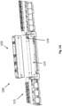
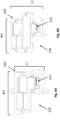
- the PDU 100 of Figure 1 is a modular PDU that includes mechanically-independent modules 110, 115, 120. As can be better seen in Figure 1A , the modules 110, 115, 120 are not mechanically connected to each other, but are instead secured directly to the housing 123 (not shown in Figure 1A ) at connection locations 124. Wires are used to connect the modules to each other. Standardized connection points such as busbars or connector locations may be employed.
- an upper portion of the communication module 120 can be temporarily removed from the PDU to allow power supplies to be replaced or for other equipment to be serviced.
- the communication module 120 can also be mounted remotely from the PDU at an angle, to allow it to be more easily viewed.
- busbar system described below may be used in non-modular systems.
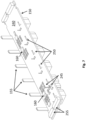
- FIG 2 shows a perspective view of a section 125 of one outlet module 115, with the outlets 130 facing downwards.
- the components of outlet module section 125 are more easily seen in Figure 3 , which depicts an exploded drawing of outlet module section 125 from the same perspective as in Figure 2 .
- the outlet module section 125 in this embodiment has a group of six outlets 130.
- each outlet module 115 has three outlet module sections 125 each with a group of six outlets, and two additional smaller outlet module sections 125 each with a group of three outlets.
- the components and functioning of each outlet module section may be similar, so only outlet module section 125 will be described in detail below.
- a set of busbars runs the length of the entire outlet module 115 in the present embodiment, and delivers current to the outlets 130 in each outlet module section 125.
- the set of busbars includes six busbars 135, portions of which are shown in Figure 2 .
- Jumpers 145 connect the busbars 135 to the appropriate pins of a printed circuit board assembly (“PCBA”) 150, which are electrically connected to outlets 130. Jumpers 145 are further connected to pins of outlets 130.
- PCBA printed circuit board assembly
- PCBA 150 includes a number of PCBA pins 155 that correspond to the number of outlets 130 in the outlet module section 125.
- PCBA 150 further includes two microprocessors 160 that communicate with communications module 120 and a separate relay board (i.e., a printed circuit board assembly) 170.
- Relay board 170 contains relays 175 and LEDs.
- chassis 185 is a one-piece frame that extends the length of the outlet module 115 and receives each outlet module section 125.
- Chassis 185 is made from a metal, such as aluminum or an aluminum alloy, and extends the entire length of the outlet module 115.
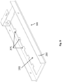
- Single chassis 185 includes a plurality of openings 190 (one of which is more clearly shown in Figure 9 ), each opening sized to receive all outlets of an outlet module section 125 in a snap-fit type interface.
- the chassis 185 in this embodiment includes five openings 190, to receive all five-outlet module sections 125.
- Each outlet 130 includes an outlet pin 195 extending in a direction opposite the outlet face.
- multiple outlets 130 are disposed in one molded plastic assembly that includes an integrated busbar for grounding all of the outlets. Grounding path provides grounding for equipment plugged into each outlet 130.
- an individual outlet is disposed in each assembly.
- outlet module section 125 Additional details of the outlet module section 125 and its components are shown in Figures 4-11 .
- Busbars 135 are included in each outlet module 115.
- Busbars 135 are made from a conductive material, such as phosphor bronze, copper or an alloy.
- Each of the busbars 135 is connected via wiring to one of three circuit protection devices in the power module 110 (not shown).
- Each circuit protection device receives power from one of the three current phases received via the plug 105 from an external source.
- Three of the busbars, P1, P2, and P3, carry input current corresponding to their respective phases.
- busbars N1, N2, and N3 are neutral lines (electrically connected to either a different phase or an actual neutral) that each complete a circuit with the respective busbars P1, P2, and P3 when busbars are joined to the pins 155, 195 with jumpers 145.
- busbar P1 is electrically connected at one end to a circuit protection device, and at another portion to one of the PCBA pins 155 that is in turn connected to an outlet 130.
- Busbar N1 connects to the corresponding outlet pin 195 on the same outlet 130, and at another end either to a circuit protection device or directly to a neutral.
- Each outlet 130 is thus connected to one of the busbars P1, P2, and P3 via a pin 155, and also connected to the corresponding busbar N1, N2, and N3 via a pin 195.
- the circuit including the circuit protection device, busbars P1 and N1, outlet 130, and user equipment is closed, thereby providing power to the user equipment.
- busbars In alternative embodiments (not shown), greater or fewer than six busbars may be used. For example, four or eight busbars may be employed. In other alternative embodiment (not shown), jumpers could be soldered to busbars and pins, or could be connected via any other permanent connection means.
- FIG. 5 shows a detailed view of jumpers 145 and busbar cap 140.
- Jumpers 145 are configured to connect a pin (either PCBA pin 155 or outlet pin 195) to a busbar 135.
- Jumpers 145 can be made with a plastic (or other non-conductive material) housing 205 and a conductive element 210, such as copper or phosphor bronze.
- Conductive element 210 is located on the bottom of a groove 215 in each jumper 145.
- Housings 205 each include one opening 220.
- Conductive element 210 is affixed to housing 205 such that conductive element 210 extends into the opening 220 and meets pin 155 or 195 when the pin is inserted into opening 220.
- Conductive element 210 lines the inner walls of opening 220, such that when pin 155 or 195 is inserted, the pin fits snugly into opening 220.
- Grooves 215 of jumpers 145 are sized and shaped to receive a busbar 135.
- Conductive element 210 is located at a bottom of groove 215, so that when a busbar 135 is placed therein, the busbar fits snugly into groove 215 and meets conductive element 210.
- the conductive element 210 By installing jumpers 145 onto both a pin 155, 195 and busbar 135, the conductive element 210 thereby provides an electrical connection between the pin and busbar.
- jumpers may be used in place of jumpers to connect the pins to the busbars, such as conductive wires.
- FIGs 6A and 6B illustrate detailed views of jumpers 145, including a small jumper 225 in Figure 6A and a large jumper 230 in Figure 6B .
- small jumper 225 is sized to connect a pin 155 or 195 to an adjacent busbar 135, while large jumper 230 is sized to connect a pin 155 or 195 to a busbar 135 located further away.
- the large jumper 230 can be sized to connect a pin to a busbar that is two busbars away, three busbars away, or more than three busbars away.
- Small jumper 225 includes a width W1 and a length L1, and large jumper 230 includes a width W2 and a length L2. In this embodiment, L2 is greater than L1, and W1 is equal to W2. In alternative embodiments (not shown), W1 may be greater or less than W2.
- small jumpers 225 are configured such that openings 220 are close to grooves 215, and are used for connections where the respective pin 155 or 195 is adjacent to the busbar 135 to which it is to be connected.
- Large jumpers 230 are configured such that openings 220 are farther away from grooves 215, and are used for connections where the respective pin 155 or 195 is not adjacent to the busbar 135 to which it is to be connected.
- jumpers could take other forms different from the form shown in Figure 5 , as long as the jumper is capable of providing an electrical connection between a pin and a busbar.
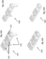
- busbar cap 140 is configured to be included on one or both ends of the set of busbars 135, to maintain the spacing between busbars 135.
- Busbar cap 140 includes two protruding arms 235 that snap onto PCBA 150.
- FIG. 5A illustrates a detailed view of an alternative embodiment of jumpers 145 and busbar caps 140a.
- each busbar cap 140a may attach to the outlet module faceplate by a stand 235a.
- the busbar caps may be configured to only attach only to the busbars.
- the busbar caps may be omitted.
- the PCBA 150 has a primary surface 240, and includes six PCBA pins 155 extending away from the primary surface 240 in a perpendicular direction.
- Each PCBA pin 155 is electrically connected to a relay 175 on relay board 170, which in turn is electrically connected to an outlet 130 via a line terminal of the outlet (not shown), so that each outlet 130 is electrically connected to a single PCBA pin 155.
- pins 155 may be mounted directly on relay board 170 and electrically connected to relays 175 as shown in Figures 19A-C and described below.
- PCBA 150 further includes two microprocessors 160 that receive signals from a plurality of sensors 245 that corresponds to measurements relevant to the power distribution, such as current and voltage, from which power and energy can be calculated. Microprocessors 160 further communicate this information to the communications module 120.
- PCBA 150 further includes a plurality of pin slots 250 sized and shaped to receive outlet pins 195.
- PCBA 150 further includes communication ports 255 that connect to communication ports on relay boards 170 for communication and control purposes, so that microprocessors 160 can receive signals from and send control signals to elements on relay board 170 and communications module 120.
- PCBAs 150 can include a different arrangement of components, such as a single microprocessor, other logic elements, and/or a microcontroller.
- PCBAs 150 of adjacent outlet module sections 125 are connected to one another via communications ports 255.
- adjacent outlet module sections may be connected to one another through a second communications port (not shown).
- relay board 170 includes a plurality of relays 175 that are configured to distribute power to outlets 130.
- Relay board 170 further includes communication ports 260 that can be connected to communication ports 255 of PCBA 150.
- Relays 175 can be switched on or off via control signals sent from microprocessors 160 and received through communication ports 260.
- Each relay 175 is electrically connected to a corresponding outlet 130, and allows electricity to pass to that outlet 130.
- Relay board 170 further includes light emitting diodes ("LEDs”), which are observable to users of the PDU 100.
- LEDs light emitting diodes
- LEDs can provide information related to the operating status of each outlet or group of outlets, such as whether current is flowing to a particular outlet, whether a threshold current has been exceeded, or whether the relay 175 corresponding to that outlet is open or closed.
- Relay board 170 further includes a plurality of slots 270 that are sized and shaped to receive outlet pins 195 there through.
- FIG 9 shows a portion of chassis 185, which is configured to receive outlets 130 in a snap-fit engagement.
- Chassis 185 extends the entire length of the outlet module 115 in the present embodiment, and includes openings 190 (one opening 190 is shown in Figure 9 ) that receive the outlets 130 of each outlet module section 125.
- the opening 190 includes protrusions 275 that align with indentations on outlets 130, allowing the outlets 130 to be in alignment when installed.
- Chassis 185 further includes fastener holes 280 on sidewalls of chassis 185 that are configured to receive mechanical fasteners (not shown) that are used to fix the outlet module 115 to housing 123.
- FIG 10 shows outlets 130 in one outlet module section 125.
- Outlets 130 each include an outlet pin 195 extending away from a socket surface of the outlet 130.
- the outlets 130 are a group in one-piece plastic, and an integrated ground busbar 200 provides electrical ground to all six outlets.
- Alternative embodiments may include individual plastic outlets arranged in a group that do not have ground busbar 200.
- Outlets 130 are also all attached to outlet faceplate 285. Outlets 130 can be fixed to faceplate 285 via a snap-fit type connection, through use of an adhesive, or with mechanical fasteners. Outlets 130 further include indentations 290 that align with protrusions 275 of chassis openings 190, to provide an aligned and secure connection therewith. Each outlet 130 is further electrically connected to a relay 175 via mating electrical conductor elements located on relay 175 and outlet 130, so that outlets 130 receive current through relays 175. In the outlet module section 125 shown, six outlets 130 are provided, but in alternative embodiments (not shown), fewer or greater outlets may be provided in an outlet module section.
- FIG 11A illustrates a more detailed view of one embodiment of a busbar cap 140.
- Busbar cap 140 includes two protruding arms 235 that snap onto PCBA 150.
- Busbar cap 140 further includes a plurality of busbar cap grooves 295, which are sized and shaped to receive busbars 135 therein.
- Busbar cap grooves 295 are sized so that busbars 135 fit snugly within the grooves 295.
- Busbar cap 140 further includes a back wall 297, so that busbars 135 cannot extend beyond busbar cap 140.
- FIG 11B illustrates an alternative embodiment of a busbar cap 300.
- the busbar cap 300 may be referred to as an intermediate busbar cap, which is substantially the same as busbar cap 140, except for the omission of a back wall.
- Intermediate busbar cap 300 can be used in between the ends of busbars 135, to provide guidance and spacing for the busbars in an intermediate location.
- busbar cap 300 can be used at the ends of busbars 135.
- FIGS 11C and 11D illustrate other alternative embodiments of a busbar cap 400 and an intermediate busbar cap 500.
- Busbar cap 400 and intermediate busbar cap 500 are substantially the same as busbar cap 140 and intermediate busbar cap 300, respectively, except that they lack protruding arms and thus do not snap onto PCBA 150.
- FIGS 11E and 11F illustrate a front and rear detailed view, respectively, of an alternative embodiment of a busbar cap 140a.
- the busbar cap 140a may attach to the outlet module faceplate by a stand 235a.
- the busbar cap 140a is otherwise substantially similar to the busbar cap 140 described above.
- FIG 11G is a detailed view of an alternative view of a busbar spacer 510.
- the busbar spacer 510 is an integrated component that includes busbar grooves 520 and wire route guides 530.
- the busbar grooves are sized so that busbars 135 fit snugly within the grooves 530.
- the wire route guides 530 are sized to retain a wire.
- FIG 12 depicts a detail view of the interface between outlet modules 115 and communications module 120.
- the outlet modules 115 are not connected to the communications module 120, and are not mechanically connected to each other. There are no mechanical structures that connect outlet modules 115 to communications module 120, or to each other.
- the busbars 135 of each outlet module 115 are electrically connected via wires 298, so that each busbar 135 is individually electrically connected to its corresponding busbar in the other outlet module.
- Wires 298 do not provide any structural or mechanical support, and merely pass electricity from one outlet module to the other. With this arrangement, the busbars in the outlet modules are connected to the same circuit protection devices in power module 110.
- Communications module 120 includes data wires (not shown) that separately connect to each of the PCBAs 150 of the outlet module sections 125, allowing independent data communication between the communications module 120 and each outlet module 115. Communications module 120 further includes through holes 299 that are sized and shaped to receive mechanical fasteners (not shown) for affixing housing 123 to communications module 120.
- the busbars 135 could run the length of the entire PDU 100, eliminating the need for wires 298.
- the busbars in the outlet module further away from the power module could be independently electrically connected to three of the circuit protection devices, while the busbars in the closer outlet module are connected to the three other circuit protection devices. In such an arrangement, each outlet module would independently receive electricity from the power module.
- outlets 130 are snapped into chassis openings 190, so that protrusions 275 of the chassis openings 190 are aligned with indentations 290 in the outlets 130.
- Relay board 170 is then placed over outlets 130, so that slots 270 receive outlet pins 195 extending from outlets 130.
- the outlet pins 195 are then soldered to the relay board 170 to provide a permanent electrical connection.
- the outlets 130 and relay board 170 are permanently fixed to the chassis 185, and cannot be removed.
- the PCBA 150 is set on top of the relay board 170, such that the PCBA slots 250 receive outlet pins 195.
- PCBA 150 can be soldered to pins 195, and/or fixed to the relay board 170 using mechanical fasteners, such as screws or bolts.
- the communication ports 255 on PCBA 150 and communication ports 260 on relay board 170 are connected with communications cables.
- jumpers 145 are connected to the pins 155, 195, so that each outlet 130 can be connected to both a busbar that provides current and the corresponding neutral busbar, to complete a circuit.
- the busbars 135 are then placed in grooves 215 in the top of jumpers 145, and spaced apart with a busbar cap or spacer 140. This same process is repeated for each outlet module section 125 in outlet module 115, using the same chassis 185 and same set of busbars 135.
- Data connections are made between the PCBAs 150 of each outlet module section 125 in the entire outlet module 115.
- Busbars 135 are then connected to the circuit protection devices in power module 110 via wiring or other conductors.
- Outlet module 115 is then placed adjacent to power module 110 on one side and adjacent to communications module 120 on the other side.
- a second outlet module 115 can be placed adjacent to the other side of communications module 120.
- the busbars 135 of each outlet module 115 are electrically connected via wires 298, which provide no structural or mechanical support.
- Data connections are then individually made between the communications module 120 and the outlet modules 115.
- the housing 123 is then separately fastened to the power module 110, outlet modules 115, and communication module 120 using mechanical fasteners that engage with holes 280, 299 of chassis 185 and communication module 120, respectively.
- Each module is individually and separately attached to the housing 123, and no module is mechanically fastened to any other module.
- the only connections between modules are non-structural electrical or data connections.
- the busbars can extend from the power module of the PDU through all other modules included in the PDU, eliminating the need for wires 298.
- other arrangements of modules may be used in the PDU, such as a separate circuit protection device module, fewer or greater than two outlet modules, fewer or greater than one communications module, and combinations thereof.
- two outlet modules can be electrically connected to separate sets of three circuit protection devices (using wiring for example), and are not electrically connected to each other at all.
- the number of busbars can be fewer or greater than six, for example, four or eight busbars may be employed.
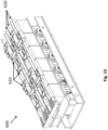
- Figure 13 illustrates an alternative embodiment of an outlet module section 600, where jumpers 610 are located outside of busbars 620.
- the functionality of the components are identical to that of the embodiment of Figures 1-12 , except that the jumpers 610 are located on the outside of busbars 620.
- Jumpers 610 still provide the same functionality, and are configured to connect the busbars 620 to pins, but are installed on the outlet module section 600 after the busbars 620 have been placed in the appropriate positions over the outlet module section 600.
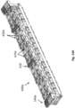
- FIG. 13A illustrates a perspective view of another alternative embodiment of an outlet module 600a, with jumpers 610a located outside of busbars 620a.
- the outlet module 600a further includes the alternative busbar caps 140a and the busbar spacers 510 described above.
- Figure 14 illustrates a top view of the outlet module section 600, to better show the jumpers 610 affixed to busbars 620. As seen in Figure 14 , both small and large jumpers 610 are used to connect pins to adjacent or distal busbars 620.
- FIG 15 illustrates an alternative embodiment of an outlet module section 700, which includes busbar insulators 710 and pin insulator 720.
- Outlet module section 700 otherwise includes identical components as the outlet module section 125 described above with respect to Figures 1-12 , and functions identically to outlet module section 125.
- Busbar insulators 710 separate adjacent busbars 730 to prevent the busbars 730 from touching, eliminating the possibility of a short circuit.
- Pin insulator 720 further ensures that none of the pins comes into contact with each other or an intermediary conductor, also preventing the possibility of a short circuit.
- Figure 16 illustrates the outlet module section 700 in an assembled condition.
- busbar insulators 710 prevent adjacent busbars from touching, and pin insulator 720 separates pins from one another, as well as provides an electrically insulated layer between the busbars 730 and PCBA 740.
- FIG 17 illustrates another embodiment of an outlet module section 800 that omits a PCBA and relay board.
- Outlet module section 800 in this embodiment is part of a simple PDU that does not include outlet switching or outlet metering, and it may or may not include a communications module.
- the outlet module section 800 includes a plurality of outlets 810 fixed to a chassis 820, and further includes a flat insulator sheet 830 resting on one side of outlets 810. Flat insulator sheet 830 is designed to prevent short circuits.
- Each outlet 810 further includes two-outlet pins 840 extending from a back side of each outlet.
- the outlet module section 800 does not include relays, so each outlet 810 includes two outlet pins 840 to complete a circuit with busbars 850.
- Busbars 850 provide power to the outlet module section 800 and jumpers 860 connect the busbars 850 to the outlet pins 840.
- Jumpers 860 are sized and shaped similar to the jumpers shown in the embodiments discussed above, and provide an electrical connection between outlet pins 840 and busbars 850 as discussed in earlier embodiments.
- FIG. 18 shows the outlet module section 800 in an exploded view, to better illustrate the flat insulator sheet 830 resting between the outlets and the jumpers 860.
- Flat insulator sheet 830 separates the outlet pins 840 from each other, and provides an insulating layer between the current-carrying busbars 850 and the outlets 810.
- Flat insulator sheet 830 includes a plurality of slots sized and shaped to receive one of outlet pins 840, to permit an electrical connection between the outlets and busbars via outlet pins 840 only. The flat insulator sheet 830 thereby prevents any accidental contact between conductive elements to prevent short-circuiting.
- the flat insulator sheet can be omitted, or a plurality of insulator sheets can be included instead of a single flat insulator sheet.
- FIGS 19A and 19B illustrate upper and lower perspective views of an alternative embodiment of an outlet module section 900 for a power distribution unit.
- the outlet module section 900 includes an outlet on/off control, voltage and current measurement, and can support alternating phase arrangements.
- the outlet module section 900 includes a plurality of long neutral/line pins 910 that extends from each outlet 920 through current transformers 930.
- the current transformers 930 measure the current through the long neutral/line pins 910 and are attached to a printed circuit board 935.
- the outlet module section 900 further includes a plurality of long tabs 950 that are attached to a printed circuit board 940 having relays 960 mounted thereon.
- the long tabs 950 are soldered to the printed circuit board 940 and can function as extensions of short neutral/line pins (not shown).
- the long neutral/line pins 910 and the long tabs 950 can be connected by jumpers (such as the jumpers discussed above) or other electrical connectors to busbars or wires to realize an alternating-phase arrangement.
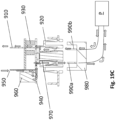
- Figure 19C is a cross-section of the outlet module section 900.
- the current travels from the long tab 950 to the printed circuit board 940 through a relay 960.
- the direction of the current is shown by the series of arrows.
- the relay 960 can control the on/off of the outlet 920.
- a short pin 970 of the outlet 920 is connected to the printed circuit board 940.
- a plug 980 having first and second pins 990a,b provides power to equipment E.
- the first pin 990a contacts the short pin 970 and the second pin 990a contacts the long neutral/line pin 910. The current thus travels through the long pin 910 as shown, so that the current transformer 930 can measure the current.
- Figure 20 is a perspective view of one embodiment of an input module connected 1000 to an output module 1010.
- the input module 1000 includes wires 1020 that are received by a busbar end cap 140a on the output module 1010 and are thereby connected to busbars 610a.
Landscapes
- Engineering & Computer Science (AREA)
- Microelectronics & Electronic Packaging (AREA)
- General Engineering & Computer Science (AREA)
- Physics & Mathematics (AREA)
- Theoretical Computer Science (AREA)
- Power Engineering (AREA)
- Computer Hardware Design (AREA)
- Optics & Photonics (AREA)
- General Physics & Mathematics (AREA)
- Details Of Connecting Devices For Male And Female Coupling (AREA)
- Connector Housings Or Holding Contact Members (AREA)
Claims (13)
- Stromverteilungseinheit, kurz PDU (100), umfassend:eine Eingangsstromkomponente (110), die eine Schaltungsschutzvorrichtung enthält;eine Ausgangskomponente (115, 125; 600; 700; 800; 900), die eine Vielzahl von Ausgängen (130; 810; 920) einschließt, die dauerhaft an einem Chassis (185; 820) befestigt sind, wobei jeder Ausgang (130; 810; 920) einen Ausgangsstift (195) und eine Vielzahl von Stromschienen (135; 620; 730; 850) einschließt, die sich über die Länge der Ausgangskomponente (115, 125; 600; 700; 800; 900) erstrecken,
wobei die Vielzahl von Stromschienen (135; 620; 730; 850) elektrisch mit einer Vielzahl von Schaltungsschutzvorrichtungen verbunden sind;wobei jeder der Vielzahl von Ausgängen (130; 810; 920) über eine Vielzahl von Steckbrücken (145, 225, 230; 610; 860) elektrisch mit den Stromschienen (135; 620; 730; 850) verbunden ist,wobei jede der Vielzahl von Steckbrücken ein Gehäuse (205) umfasst, wobei jedes Gehäuse eine Öffnung (220), eine Nut (215) und ein leitendes Element (210) umfasst;wobei sich das leitende Element (210) in die Öffnung (220) erstreckt und so konfiguriert ist, dass es auf den Ausgangsstift (195) trifft, wenn der Stift (195) in die Öffnung (220) eingeführt wird;wobei jede Nut (215) jeder der Steckbrücken (145, 225, 230; 610; 860) so bemessen und geformt ist, dass sie eine Stromschiene der Vielzahl von Stromschienen (135; 620; 730; 850) aufnimmt und so konfiguriert ist, dass sie auf das leitende Element (210) trifft;wobei die Vielzahl von Steckbrücken (145, 225, 230; 610; 860) eine erste Steckbrücke (225) und eine zweite Steckbrücke (230) einschließt,wobei die erste Steckbrücke (225) so konfiguriert ist, dass die Öffnung (220) in der Nähe der Nut (215) liegt, und so konfiguriert ist, dass sie für Verbindungen verwendet wird, bei denen der Ausgangsstift (195) an eine erste Stromschiene angrenzt, mit der er verbunden werden soll;wobei die zweite Steckbrücke (230) so konfiguriert ist, dass die Öffnung (220) weiter von der Nut (215) entfernt ist als die erste Steckbrücke (230) und für Verbindungen verwendet wird, bei denen der Ausgangsstift (195) nicht an eine zweite Stromschiene angrenzt, mit der er verbunden werden soll;wobei die erste Steckbrücke (225) einen ersten Ausgang der Vielzahl von Ausgängen (130; 810; 920) elektrisch mit einer ersten Stromschiene der Vielzahl von Stromschienen (135; 620; 730; 850) verbindet,wobei die erste Stromschiene an den ersten Ausgang angrenzt,wobei die zweite Steckbrücke (230) einen zweiten Ausgang der Vielzahl von Ausgängen (130; 810; 920) elektrisch mit einer zweiten Stromschiene der Vielzahl von Stromschienen (135; 620; 730; 850) verbindet undwobei sich die zweite Stromschiene nicht an den zweiten Ausgang angrenzt;eine Kommunikationskomponente (120) in Signalkommunikation mit der Ausgangskomponente (115, 125; 600; 700; 800; 900) zum Übertragen von Daten; undein Gehäuse (123), das mit der Eingangsstromkomponente (110), der Ausgangskomponente (115, 125; 600; 700; 800; 900), und der Kommunikationskomponente (120) verbunden ist. - PDU (100) nach Anspruch 1, ferner umfassend eine zweite Ausgangskomponente,
wobei die zweite Ausgangskomponente eine zweite Vielzahl von Ausgängen einschließt, die dauerhaft an einem zweiten Chassis befestigt sind, und eine Vielzahl von zweiten Stromschienen, die sich über die Länge der zweiten Ausgangskomponente erstrecken. - PDU (100) nach Anspruch 1 oder 2, wobei die Vielzahl von Ausgängen (130; 810; 920) mehrere erste Gruppen von Ausgängen einschließt.
- PDU (100) nach Anspruch 3, wobei jede erste Gruppe von Ausgängen eine erste Leiterplattenanordnung, kurz PCBA, (150; 740; 940) mit mindestens einem Mikroprozessor (160) einschließt.
- PDU (100) nach Anspruch 3, wobei jede erste Gruppe von Ausgängen eine Relaiskarte (170) einschließt, die eine Vielzahl von Relais (175; 960) enthält, wobei jedes Relais (175; 960) in der Lage ist, einen Ausgang (130; 810; 920) mit einer Stromschiene (135; 620; 730; 850) elektrisch zu verbinden oder zu trennen.
- PDU (100) nach Anspruch 1, wobei jeder Ausgang (130; 810; 920) einen elektrisch leitenden Ausgangsstift (195; 840; 910, 970) einschließt, der elektrisch mit einer der Vielzahl von Steckbrücken (145, 225, 230; 610; 860) verbunden ist.
- Verfahren zum Zusammenbau einer Stromverteilungseinheitsanordnung (100), umfassend:Bereitstellen eines Gehäuses (123);mechanisches Verbinden einer Stromquelle (P) mit dem Gehäuse (123);mechanisches Verbinden einer Vielzahl von Ausgängen (130; 810; 920) mit dem Gehäuse (123), wobei die Vielzahl von Ausgängen (130; 810; 920) mindestens einen ersten Ausgang und einen zweiten Ausgang einschließt, und wobei jeder Ausgang (130; 810; 920) einen Ausgangsstift (195) einschließt;Bereitstellen eines Satzes von Stromschienen (135; 620; 730; 850), wobei der Satz von Stromschienen (135; 620; 730; 850) mindestens eine erste Stromschiene und eine zweite Stromschiene einschließt; undelektrisches Verbinden einer Vielzahl von Steckbrücken (145, 225, 230; 610; 860) von mindestens einigen der Vielzahl von Ausgängen (130; 810; 920) mit dem Satz von Stromschienen (135; 620; 730; 850),wobei jede der Vielzahl von Steckbrücken ein Gehäuse (205) umfasst, wobei jedes Gehäuse eine Öffnung (220), eine Nut (215) und ein leitendes Element (210) umfasst;wobei sich das leitende Element (210) in die Öffnung (220) erstreckt und so konfiguriert ist, dass es auf den Ausgangsstift (195) trifft, wenn der Stift (195) in die Öffnung (220) eingeführt wird;wobei jede Nut (215) jeder der Steckbrücken (145, 225, 230; 610; 860) so bemessen und geformt ist, dass sie eine Stromschiene der Vielzahl von Stromschienen (135; 620; 730; 850) aufnimmt und so konfiguriert ist, dass sie auf das leitende Element (210) trifft;wobei die Vielzahl von Steckbrücken (145, 225, 230; 610; 860) eine erste Steckbrücke (225) und eine zweite Steckbrücke (230) einschließt,wobei die erste Steckbrücke (225) so konfiguriert ist, dass die Öffnung (220) in der Nähe der Nut (215) liegt, und so konfiguriert ist, dass sie für Verbindungen verwendet wird, bei denen der Ausgangsstift (195) an eine erste Stromschiene angrenzt, mit der er verbunden werden soll;wobei die zweite Steckbrücke (230) so konfiguriert ist, dass die Öffnung (220) weiter von der Nut (215) entfernt ist als die erste Steckbrücke (230) und für Verbindungen verwendet wird, bei denen der Ausgangsstift (195) nicht an eine zweite Stromschiene angrenzt, mit der er verbunden werden soll;wobei die erste Steckbrücke (225) den ersten Ausgang elektrisch mit der ersten Stromschiene verbindet, wobei die erste Stromschiene an den ersten Ausgang angrenzt, undwobei die zweite Steckbrücke (230) den zweiten Ausgang elektrisch mit der zweiten Stromschiene verbindet, wobei die zweite Stromschiene nicht an den zweiten Ausgang angrenzt.
- Verfahren nach Anspruch 7, wobei der Satz von Stromschienen (135; 620; 730; 850) einen ersten Satz von Stromschienen und einen zweiten Satz von Stromschienen einschließt, und wobei das Verfahren ferner das elektrische Verbinden des ersten Satzes von Stromschienen mit dem zweiten Satz von Stromschienen über einen oder mehrere Drähte (298) einschließt.
- Verfahren nach Anspruch 7, wobei der Satz von Stromschienen (135; 620; 730; 850) einen ersten Satz von Stromschienen und einen zweiten Satz von Stromschienen einschließt, und wobei der erste Satz von Stromschienen und der zweite Satz von Stromschienen nicht elektrisch miteinander verbunden sind.
- Verfahren nach einem der Ansprüche 7 bis 9, das ferner das mechanische Verbinden eines Kommunikationsmoduls (120) mit dem Gehäuse (123) einschließt.
- Verfahren nach Anspruch 10, wobei es keine direkten mechanischen Verbindungen zwischen der Stromquelle (P), der Vielzahl von Ausgängen (130; 810; 920) oder dem Kommunikationsmodul (120) gibt.
- Verfahren nach einem der Ansprüche 7 bis 11, wobei mindestens eine des Satzes von Stromschienen (135; 620; 730; 850) einen Eingangsstrom führt, wobei mindestens eine des Satzes von Stromschienen (135; 620; 730; 850) eine neutrale Leitung ist, und wobei jeder der Vielzahl von Ausgängen (130; 810; 920) durch eine erste Steckbrücke mit einem Eingangsstrom und durch eine zweite Steckbrücke mit einer neutralen Leitung verbunden ist.
- Verfahren nach einem der Ansprüche 7 bis 12, wobei mindestens eine des Satzes von Stromschienen (135; 620; 730; 850) Strom von einer ersten elektrischen Phase führt, wobei mindestens eine des Satzes von Stromschienen (135; 620; 730; 850) Strom von einer zweiten elektrischen Phase führt, und wobei das Verfahren ferner das elektrische Verbinden jeder der Vielzahl von Ausgängen (130; 810; 920) mit einer ersten Phase durch die erste Steckbrücke (225) und mit der zweiten Phase durch eine zweite Steckbrücke (230) einschließt.
Applications Claiming Priority (2)
| Application Number | Priority Date | Filing Date | Title |
|---|---|---|---|
| US15/884,832 US10524377B2 (en) | 2018-01-31 | 2018-01-31 | Power distribution unit with interior busbars |
| PCT/EP2019/025031 WO2019149453A1 (en) | 2018-01-31 | 2019-01-31 | Power distribution unit with interior busbars |
Publications (2)
| Publication Number | Publication Date |
|---|---|
| EP3747246A1 EP3747246A1 (de) | 2020-12-09 |
| EP3747246B1 true EP3747246B1 (de) | 2024-12-18 |
Family
ID=65686793
Family Applications (1)
| Application Number | Title | Priority Date | Filing Date |
|---|---|---|---|
| EP19709369.3A Active EP3747246B1 (de) | 2018-01-31 | 2019-01-31 | Stromverteilungseinheit mit innenliegenden stromschienen |
Country Status (4)
| Country | Link |
|---|---|
| US (2) | US10524377B2 (de) |
| EP (1) | EP3747246B1 (de) |
| CN (1) | CN112042284B (de) |
| WO (1) | WO2019149453A1 (de) |
Families Citing this family (11)
| Publication number | Priority date | Publication date | Assignee | Title |
|---|---|---|---|---|
| JP7106628B2 (ja) * | 2017-08-01 | 2022-07-26 | 陳国良 | 拡張・更新可能な可変コンセント |
| US10879647B2 (en) * | 2018-03-16 | 2020-12-29 | Fci Usa Llc | Double pole power connector |
| US10938191B2 (en) | 2018-10-31 | 2021-03-02 | Eaton Intelligent Power Limited | Heat dissipation structures for power distribution units |
| US10993349B2 (en) * | 2018-11-14 | 2021-04-27 | Legrand Av Inc. | Distributable modular chassis |
| CN111817067A (zh) | 2019-04-12 | 2020-10-23 | 富加宜连接器(东莞)有限公司 | 电连接器、电连接器组件、电设备和电互连系统 |
| USD975024S1 (en) | 2019-04-12 | 2023-01-10 | Fci Connectors Dongguan Ltd. | Electrical connector |
| US11910554B2 (en) | 2021-02-23 | 2024-02-20 | Cisco Technology, Inc. | Modular and pluggable PDU to power tray/shelf device |
| CN113363746B (zh) * | 2021-08-09 | 2021-11-09 | 突破电气(天津)有限公司 | 一种pdu配电装置 |
| CN115036761A (zh) * | 2022-07-06 | 2022-09-09 | 周庆玉 | 一种智能pdu电源分配器 |
| USD1078666S1 (en) * | 2022-09-26 | 2025-06-10 | Bitmain Technologies Inc. | Power distribution unit |
| AU2024202796B2 (en) * | 2023-05-03 | 2025-12-04 | Schneider Electric Industries Sas | Communicating arrangement for fishbone busbar assembly |
Family Cites Families (171)
| Publication number | Priority date | Publication date | Assignee | Title |
|---|---|---|---|---|
| GB584414A (en) * | 1944-11-13 | 1947-01-14 | Humber Ltd | Improvements relating to systems of electrical distribution |
| FR2547694B2 (fr) | 1983-06-17 | 1988-01-22 | Pgep Sa | Dispositif modulaire de distribution d'energie electrique |
| US4740167A (en) | 1984-03-02 | 1988-04-26 | Amp Incorporated | Power distribution unit for modular wall panels |
| FR2573274B2 (fr) | 1984-11-14 | 1987-01-23 | Professional Gl Electronic Pro | Dispositif modulaire de distribution d'energie electrique |
| US5340326A (en) * | 1988-07-18 | 1994-08-23 | Lemaster Dolan M | Connectivity management system |
| FR2646737B1 (fr) | 1989-05-03 | 1991-07-26 | Telemecanique | Dispositif repartiteur de puissance pour installation electrique |
| FR2649550B1 (de) | 1989-07-06 | 1991-10-11 | Telemecanique | |
| US5203713A (en) | 1989-08-16 | 1993-04-20 | Amp Incorporated | Power distribution system for modular furniture unit |
| US5207613A (en) | 1991-07-08 | 1993-05-04 | Tandem Computers Incorporated | Method and apparatus for mounting, cooling, interconnecting, and providing power and data to a plurality of electronic modules |
| US5203711A (en) | 1991-10-01 | 1993-04-20 | Molex Incorporated | Modular interchangeable power distribution system |
| US5425659A (en) * | 1992-06-22 | 1995-06-20 | Sl Waber, Inc. | Multiple electrical outlet strip module |
| GB2269052B (en) | 1992-07-17 | 1995-11-01 | Square D Co | Improvements in power switchboards |
| US5429518A (en) * | 1994-03-07 | 1995-07-04 | Chen; Ken C. | Socket terminal |
| US6377874B1 (en) | 1994-09-07 | 2002-04-23 | Spd Technologies Inc. | Power distribution system including integrated power node control center |
| FR2733092B1 (fr) | 1995-04-13 | 1997-06-06 | Schneider Electric Sa | Assemblage d'appareils electriques modulaires utilisables en distribution repartie |
| US5870276A (en) | 1995-05-31 | 1999-02-09 | Square D Company | Electrical power distribution device with elevated removable load center |
| CA2229571C (en) | 1995-09-29 | 2006-09-12 | Reltec Corporation | Modular terminal block assembly |
| US5779504A (en) | 1995-09-29 | 1998-07-14 | Reltec Corporation | Modular terminal block assembly |
| US5675194A (en) | 1996-06-07 | 1997-10-07 | Walker Systems, Inc. | Modular power distribution system |
| DE29610630U1 (de) | 1996-06-17 | 1997-11-13 | BISON stematec Maschinenbau- und Hubarbeitsbühnen Produktionsgesellschaft mbH, 02708 Löbau | Fahrbare Hubarbeitsbühne |
| US6711613B1 (en) | 1996-07-23 | 2004-03-23 | Server Technology, Inc. | Remote power control system |
| US7099934B1 (en) | 1996-07-23 | 2006-08-29 | Ewing Carrel W | Network-connecting power manager for remote appliances |
| US7171461B2 (en) | 1996-07-23 | 2007-01-30 | Server Technology, Inc. | Network remote power management outlet strip |
| US7774443B2 (en) | 1996-07-23 | 2010-08-10 | Server Technology, Inc. | Power-manager configuration upload and download method and system for network managers |
| US5949974A (en) | 1996-07-23 | 1999-09-07 | Ewing; Carrell W. | System for reading the status and for controlling the power supplies of appliances connected to computer networks |
| US7043543B2 (en) | 1996-07-23 | 2006-05-09 | Server Technology, Inc. | Vertical-mount electrical power distribution plugstrip |
| US6086397A (en) * | 1998-04-27 | 2000-07-11 | American Express Travel Related Services Company, Inc. | High reliability raised floor power strip |
| US5982610A (en) | 1998-05-27 | 1999-11-09 | Reltec Corporation | Multisided communication distribution cabinet having adjustable tie rod |
| US6015307A (en) * | 1998-10-21 | 2000-01-18 | Chiu; Pen-Fu | Electric outlet with rotary socket bodies |
| US6530811B1 (en) * | 1999-06-04 | 2003-03-11 | Astec International Limited | Modular distribution assembly |
| US6611724B1 (en) | 1999-11-24 | 2003-08-26 | Square D Company | On line monitor for a control device |
| US6220880B1 (en) * | 2000-01-27 | 2001-04-24 | Chiu-Shan Lee | Electric outlets |
| US6750410B2 (en) * | 2000-09-05 | 2004-06-15 | Jae Ha Lee | Electric outlet with rotatable receptacles |
| US6967283B2 (en) | 2001-03-20 | 2005-11-22 | American Power Conversion Corporation | Adjustable scalable rack power system and method |
| GB2375657B (en) * | 2001-05-17 | 2003-04-16 | Atom Technology Inc | Modular external power supply unit receptacle |
| US6663435B2 (en) * | 2001-06-06 | 2003-12-16 | Tyco Electronics Corporation | Electrical load balancing power module |
| US6617708B2 (en) | 2001-09-18 | 2003-09-09 | C&D Charter Holdings, Inc. | Modular power distribution system |
| US6514093B1 (en) * | 2001-10-03 | 2003-02-04 | Tsung-I Yu | Wall mounting power adapter socket |
| US6547572B1 (en) * | 2001-10-26 | 2003-04-15 | Alcoa Fujikura Limited | Integrated and flexible power distribution assembly |
| US6937461B1 (en) | 2001-11-28 | 2005-08-30 | Donahue, Iv William F. | Modular power distribution unit, module for the power distribution unit, and method of using the same |
| US6826036B2 (en) | 2002-06-28 | 2004-11-30 | Hewlett-Packard Development Company, L.P. | Modular power distribution system for use in computer equipment racks |
| US7046514B2 (en) | 2003-03-19 | 2006-05-16 | American Power Conversion Corporation | Data center cooling |
| US7112131B2 (en) | 2003-05-13 | 2006-09-26 | American Power Conversion Corporation | Rack enclosure |
| CN2634685Y (zh) | 2003-06-07 | 2004-08-18 | 深圳市日海通讯设备有限公司 | 电源分配列柜的出线装置 |
| US6940015B2 (en) * | 2003-12-09 | 2005-09-06 | I Hsiung Fang | Power outlet strip having changeable cover |
| US7196900B2 (en) | 2004-05-21 | 2007-03-27 | Server Technology, Inc. | Adaptable rack mountable power distribution apparatus |
| US7268998B2 (en) | 2004-11-01 | 2007-09-11 | Server Technology, Inc. | Ganged outlet power distribution apparatus |
| US7137850B2 (en) | 2004-11-01 | 2006-11-21 | Ewing Carrel W | Circuit link connector |
| US7400493B2 (en) | 2004-11-01 | 2008-07-15 | Server Technology, Inc. | Circuit breaking link status detection and reporting circuit |
| US8203828B2 (en) * | 2005-01-27 | 2012-06-19 | Production Resource Group Llc | Portable power and signal distribution system for a controllable system including multiple devices |
| US20060199438A1 (en) | 2005-02-15 | 2006-09-07 | Server Technology, Inc. | Ganged electrical outlets, apparatus, and methods of use |
| US6939180B1 (en) * | 2005-02-22 | 2005-09-06 | Sidney Wu | Receptacle for extension cord |
| US7394667B2 (en) | 2005-03-30 | 2008-07-01 | Emerson Network Power - Embedded Computing, Inc. | High density power distribution unit |
| US7187177B2 (en) | 2005-03-30 | 2007-03-06 | Motorola, Inc. | Method of monitoring a power distribution unit |
| US7764775B2 (en) | 2005-03-30 | 2010-07-27 | Onq/Legrand, Inc. | Distributed intercom system |
| US20060232366A1 (en) * | 2005-04-15 | 2006-10-19 | Jianshing Li | Over-current actuated reed relay and electrical outlet incorporating the same for providing over-current alarm |
| SG129318A1 (en) | 2005-07-13 | 2007-02-26 | Copper Red Pte Ltd | Modular power distribution device |
| US7377807B2 (en) | 2005-08-09 | 2008-05-27 | Eaton Corporation | Modular power distribution apparatus using cables with guarded connectors |
| US9166382B2 (en) | 2006-01-11 | 2015-10-20 | Server Technology, Inc. | Power distribution unit and methods of making and use including modular construction and assemblies |
| US7447002B2 (en) | 2006-01-11 | 2008-11-04 | Server Technology, Inc. | Fuse module with movable fuse holder for fused electrical device |
| US7675739B2 (en) | 2006-01-11 | 2010-03-09 | Server Technology, Inc. | Fuse module with removable fuse carrier for fused electrical device |
| WO2007082071A2 (en) | 2006-01-11 | 2007-07-19 | Server Technology, Inc. | Power distribution unit and methods of making and use including modular construction and assemblies |
| US7606014B2 (en) | 2006-06-16 | 2009-10-20 | American Power Conversion Corporation | Apparatus and method for scalable power distribution |
| US7619868B2 (en) | 2006-06-16 | 2009-11-17 | American Power Conversion Corporation | Apparatus and method for scalable power distribution |
| US20080076291A1 (en) | 2006-07-06 | 2008-03-27 | Server Technology, Inc. | Electrical plug retainer |
| FR2904156B1 (fr) | 2006-07-20 | 2008-11-28 | Schneider Electric Ind Sas | Dispositif de repartition de l'alimentation de puissance electrique pour une rangee d'appareils modulaires dans un tableau electrique. |
| FR2904737B1 (fr) | 2006-08-03 | 2009-04-10 | Legrand France | Ensemble de distribution pour installation electrique |
| WO2008036848A2 (en) | 2006-09-20 | 2008-03-27 | Server Technology, Inc. | Modular power distribution unit system |
| US8341837B2 (en) | 2007-05-25 | 2013-01-01 | Braunstein Zachary L | Modular power distribution and control system |
| US7940504B2 (en) | 2007-06-21 | 2011-05-10 | American Power Conversion Corporation | Apparatus and method for scalable power distribution |
| CN201061085Y (zh) | 2007-06-21 | 2008-05-14 | 山东容大电气有限公司 | 模块化智能型变配电装置 |
| EP2248044A4 (de) | 2007-12-28 | 2013-12-11 | Server Tech Inc | Systeme und verfahren zur stromversorgungsverteilung, -verwaltung und -überwachung |
| CA2878655C (en) | 2007-12-28 | 2016-12-06 | Server Technology, Inc. | Power distribution, management, and monitoring systems and methods |
| ITFI20080031A1 (it) | 2008-02-22 | 2009-08-23 | Wiva Group S R L | Dispositivo modulare per la distribuzione di alimentazione elettrica. |
| US7726825B2 (en) * | 2008-02-22 | 2010-06-01 | Leviton Manufacturing Co., Inc. | Lighted power outlet system and method |
| WO2009117500A2 (en) | 2008-03-19 | 2009-09-24 | Liebert Corporation | Adaptive power strip |
| CN102165665A (zh) | 2008-04-30 | 2011-08-24 | 力登美洲公司 | 用于电源插座和设备有效关联的系统和方法 |
| WO2009158116A2 (en) | 2008-05-30 | 2009-12-30 | Epicenter, Inc. | Method and apparatus for high-density power distribution unit with integrated cable management |
| US7759575B2 (en) | 2008-06-20 | 2010-07-20 | Tyco Electronics Corporation | Expandable power distribution unit |
| US20100019575A1 (en) | 2008-07-22 | 2010-01-28 | Christopher Eugene Verges | System and method for creating and controlling a virtual power distribution unit |
| US20100033019A1 (en) | 2008-08-06 | 2010-02-11 | Noribachi Llc | Modular solar device power distribution |
| US8093748B2 (en) | 2008-10-08 | 2012-01-10 | Avocent Huntsville Corporation | Universal power inlet system for power distribution units |
| TWM343273U (en) * | 2008-12-03 | 2008-10-21 | Well Shin Technology Co Ltd | Receptacle apparatus |
| CN201340984Y (zh) | 2008-12-31 | 2009-11-04 | 深圳市新天机电技术有限公司 | 一种采用机架式配电单元的机柜 |
| US8321163B2 (en) | 2009-03-04 | 2012-11-27 | Server Technology, Inc. | Monitoring power-related parameters in a power distribution unit |
| CN201369583Y (zh) | 2009-03-12 | 2009-12-23 | 河北实华科技有限公司 | 基于标准网络机柜的模块化电源系统 |
| US8283802B2 (en) * | 2009-06-11 | 2012-10-09 | American Power Conversion Corporation | Dual column gang outlets for minimizing installation space |
| CA2766807A1 (en) | 2009-06-25 | 2010-12-29 | Server Technology, Inc. | Power distribution apparatus with input and output power sensing and method of use |
| FR2951031B1 (fr) | 2009-10-06 | 2011-10-28 | Schneider Electric Ind Sas | Unite fonctionnelle pour tableau basse tension avec position test |
| US8212427B2 (en) | 2009-12-03 | 2012-07-03 | American Power Converison Corporation | Apparatus and method for scalable power distribution |
| JP5562054B2 (ja) * | 2010-01-29 | 2014-07-30 | 富士通株式会社 | テーブルタップ及び電力測定システム |
| CN101807775B (zh) | 2010-02-08 | 2012-03-07 | 深圳市克莱沃电子有限公司 | 模块化电源控制分配系统 |
| US8427007B2 (en) | 2010-02-24 | 2013-04-23 | Schneider Electric It Corporation | Field replaceable management module |
| US8038454B2 (en) | 2010-03-09 | 2011-10-18 | American Power Conversion Corporation | Back-mount ganged electrical outlets |
| WO2012011982A2 (en) * | 2010-04-07 | 2012-01-26 | The Wiremold Company | Customizable bus systems |
| US8305739B2 (en) | 2010-06-10 | 2012-11-06 | Schneider Electric USA, Inc. | High density power/lighting panelboard |
| US8427301B2 (en) | 2010-06-24 | 2013-04-23 | Avocent Corporation | System and method for identifying electrical equipment using wireless receivers |
| CN201726058U (zh) | 2010-07-05 | 2011-01-26 | 江苏省电力公司张家港市供电公司 | 柱上式配电站 |
| CN103168400B (zh) | 2010-09-30 | 2016-04-27 | 飓风香港有限公司 | 电源分配单元及与其配合的通讯装置、及电源分配系统 |
| US20120229515A1 (en) | 2010-10-07 | 2012-09-13 | Huimin Cao | Auto-Orientation of Display of a Power Distribution Unit |
| US9482698B2 (en) | 2010-10-07 | 2016-11-01 | Raritan Americas, Inc. | Methods and apparatus for resistive voltage sensing in an isolated power distribution unit |
| KR101479893B1 (ko) * | 2011-02-04 | 2015-01-06 | 후지쯔 가부시끼가이샤 | 테이블 탭 및 전력 측정 방법 |
| EP2501210A3 (de) | 2011-03-16 | 2017-04-26 | Hamilton Sundstrand Corporation | Leistungsverteilungseinheit und Verfahren zur Verteilung von Leistung hoher Dichte |
| CN202059085U (zh) | 2011-03-28 | 2011-11-30 | 深圳市海德森科技有限公司 | 模块化智能配电系统 |
| CN102208833B (zh) | 2011-05-13 | 2014-01-01 | 艾默生网络能源有限公司 | 一种供电系统及其模块化配电装置 |
| US8587950B2 (en) | 2011-05-31 | 2013-11-19 | Server Technology, Inc. | Method and apparatus for multiple input power distribution to adjacent outputs |
| CN103999563B (zh) | 2011-12-20 | 2017-02-15 | 施耐德电气It公司 | 智能机架外壳 |
| CN202434789U (zh) | 2012-01-16 | 2012-09-12 | 上海能巍电气科技有限公司 | 可互换式电源插座模块 |
| US9054449B2 (en) | 2012-01-27 | 2015-06-09 | Chatsworth Products, Inc. | Cable retention system for power distribution unit |
| CN102593724B (zh) | 2012-01-30 | 2015-04-22 | 深圳市泰昂能源科技股份有限公司 | 积木式快装配电装置 |
| US9301420B2 (en) | 2012-02-01 | 2016-03-29 | Dell Products L.P. | Rack-level scalable and modular power infrastructure |
| US8972752B2 (en) | 2012-02-01 | 2015-03-03 | Dell Products L.P. | System and method for providing modular and scalable power infrastructure outside of usable it space |
| US8708736B2 (en) | 2012-02-01 | 2014-04-29 | Dell Products L.P. | Systems and methods for coupling AC power to a rack-level power infrastructure |
| US9400726B2 (en) | 2012-03-23 | 2016-07-26 | Server Technology, Inc. | Power usage monitoring of power feed circuits using power distribution units |
| US9800031B2 (en) | 2012-07-26 | 2017-10-24 | Server Technology, Inc. | Multi-position input cord assembly for a power distribution unit |
| AU2013295604B2 (en) | 2012-07-26 | 2016-06-23 | Chris CONNOLLY | Multi-position input cord assembly for a power distribution unit |
| US8902569B1 (en) | 2012-07-27 | 2014-12-02 | Amazon Technologies, Inc. | Rack power distribution unit with detachable cables |
| CN202872201U (zh) | 2012-08-30 | 2013-04-10 | 南京普天鸿雁电器科技有限公司 | 一种模块化机柜配电单元 |
| TW201412224A (zh) | 2012-09-07 | 2014-03-16 | Bellwin Information Co Ltd | 熱插拔監測模組及應用彼之機櫃電力分配器 |
| US20140102746A1 (en) | 2012-10-11 | 2014-04-17 | Sandra B. WRIGHTSON | Semi-permanent modular surface mountable electric power distribution system |
| CN104904075B (zh) | 2012-11-06 | 2018-06-12 | 服务器技术股份有限公司 | 高密度插座配电单元 |
| CN202977986U (zh) | 2012-11-27 | 2013-06-05 | 深圳艺朴露科技有限公司 | 一种模块化标准机柜电源分配管理器 |
| CN202978089U (zh) | 2012-12-06 | 2013-06-05 | 深圳市欧亚特电器设备有限公司 | 模块化智能配电设备 |
| US8986030B2 (en) | 2012-12-06 | 2015-03-24 | Phoenix Contact Development and Manufacturing, Inc. | Modular electric power distribution system |
| CN103872674A (zh) | 2012-12-11 | 2014-06-18 | 华为技术有限公司 | 配电系统及配电单元 |
| CN103869877A (zh) | 2012-12-12 | 2014-06-18 | 鸿富锦精密工业(深圳)有限公司 | 机柜 |
| CN103872585A (zh) | 2012-12-18 | 2014-06-18 | 定边县新雄风农机研制有限责任公司 | 一种数据中心智能模块配电系统 |
| CN203103767U (zh) | 2013-03-06 | 2013-07-31 | 广东盾牌通讯设备有限公司 | 一种智能pdu电源分配单元 |
| WO2014145321A2 (en) | 2013-03-15 | 2014-09-18 | Server Technology, Inc. | Wireless communications capable power distribution unit and techniques for communicating therewith |
| CN104218402B (zh) | 2013-05-30 | 2018-09-21 | 伊顿制造(格拉斯哥)有限合伙莫尔日分支机构 | 一种用于电源分配单元的定位装置 |
| CN103986225B (zh) | 2013-09-02 | 2016-04-20 | 包建伟 | 带后备蓄电池式智能电源分配单元pdu |
| CN203607683U (zh) | 2013-10-29 | 2014-05-21 | 深圳市三江电气有限公司 | 一种模块化的配电装置 |
| CN203645933U (zh) | 2013-11-18 | 2014-06-11 | 深圳科士达科技股份有限公司 | 一种具有ups与配电模块的一体化机柜 |
| CN103582397B (zh) | 2013-11-18 | 2016-06-22 | 深圳科士达科技股份有限公司 | 一体化机柜 |
| CN203645962U (zh) | 2013-11-18 | 2014-06-11 | 深圳科士达科技股份有限公司 | 一体化机柜 |
| CN203661449U (zh) | 2013-11-18 | 2014-06-18 | 深圳科士达科技股份有限公司 | 一种具有pdu的一体化机柜 |
| EP2876982B1 (de) | 2013-11-21 | 2018-04-25 | Schneider Electric IT Corporation | Sperranordnung zur Sicherung von elektronischer Einrichtung in einem Einrichtungsgestell |
| CN203645149U (zh) | 2013-12-12 | 2014-06-11 | 上海杜尔瑞克智能电气成套有限公司 | 一种垂直安装直接出线式pdu |
| US9733682B2 (en) | 2013-12-19 | 2017-08-15 | VCE IP Holding Company LLC | Scalable computing rack power distribution unit |
| KR101535192B1 (ko) | 2013-12-31 | 2015-07-10 | 전자부품연구원 | 이종 전원 공급이 가능한 모듈형 pdu |
| IN2013MU02517A (de) | 2014-01-30 | 2015-09-11 | Raychem Rpg Private Ltd | |
| WO2015123478A1 (en) | 2014-02-14 | 2015-08-20 | Burant Richard J | Electrical power distribution unit |
| CN203812166U (zh) | 2014-03-12 | 2014-09-03 | 成都邮电通信设备有限公司 | 一种机架式pdu电源分配单元 |
| US9837813B2 (en) | 2014-03-17 | 2017-12-05 | Core Brands, Llc | Power distribution unit with modular charging ports |
| CN104979761B (zh) | 2014-04-14 | 2017-11-17 | 施耐德电器工业公司 | 可调节扶手和具有该可调节扶手的配电柜 |
| CN103915765A (zh) | 2014-04-14 | 2014-07-09 | 浪潮电子信息产业股份有限公司 | 一种模块化配电系统 |
| CN203951356U (zh) | 2014-05-22 | 2014-11-19 | 特变电工新疆新能源股份有限公司 | 一种光伏并网逆变器结构 |
| CN203911108U (zh) | 2014-06-03 | 2014-10-29 | 北京同为西门科技有限公司 | 一种紧凑型电源分配单元 |
| US20150370297A1 (en) | 2014-06-18 | 2015-12-24 | Microsoft Corporation | Modular power distribution for computing systems |
| US9478949B2 (en) | 2014-07-16 | 2016-10-25 | Siemens Industry, Inc. | Fusible meter stack apparatus, multi-unit power distribution apparatus, and operational methods |
| CN104393496B (zh) * | 2014-07-24 | 2017-07-14 | 四川睿联安电气有限公司 | 贯通母线卡接式超大负载容量环形配线高可靠pdu |
| CN204179497U (zh) | 2014-07-24 | 2015-02-25 | 四川睿联安电气有限公司 | Pdu多功能面板模组 |
| CN104199534A (zh) | 2014-09-16 | 2014-12-10 | 浪潮电子信息产业股份有限公司 | 一种基于双输入电源的高密度机柜节能供电装置 |
| CN204130787U (zh) | 2014-09-24 | 2015-01-28 | 广西地凯科技有限公司 | 一种机架式防雷电源插座 |
| US20160095247A1 (en) | 2014-09-30 | 2016-03-31 | Schneider Electric It Corporation | Rack mounted equipment power distribution system enhancements |
| US20160098040A1 (en) | 2014-10-02 | 2016-04-07 | Harman International Industries, Inc. | Mount for media content presentation device |
| CN204179491U (zh) | 2014-11-13 | 2015-02-25 | 艾默生网络能源(江门)有限公司 | 一种模块化配电柜 |
| CN204333678U (zh) | 2014-12-11 | 2015-05-13 | 山东泰安金恒电气有限公司 | 一种模块化配电柜 |
| CN204333679U (zh) | 2014-12-11 | 2015-05-13 | 山东泰安金恒电气有限公司 | 一种便于搬运的模块化配电柜 |
| CN107112795B (zh) | 2014-12-15 | 2021-11-19 | 伊顿智能动力有限公司 | 模块化不间断电源和电力分布系统 |
| CN204481214U (zh) | 2015-01-30 | 2015-07-15 | 深圳市海鹏信电子股份有限公司 | 可拆卸式pdu |
| EP3284147B1 (de) * | 2015-04-15 | 2023-09-27 | Server Technology, Inc. | Steckdose für eine stromverteilungseinheit mit hoher ausgangsdichtesteckdose |
| CN204667227U (zh) | 2015-05-09 | 2015-09-23 | 深圳市易信科技有限公司 | 一种能够识别温度从而控制风扇转速的idc机柜pdu |
| CN204696497U (zh) | 2015-06-12 | 2015-10-07 | 魏长柏 | 一种机架式模块化配电单元箱 |
| US9520043B1 (en) * | 2015-06-17 | 2016-12-13 | Lenovo Enterprise Solutions (Singapore) Pte. Ltd. | Identifying an outlet of a power distribution unit based on a power rating of an electronic device |
| CN105244672B (zh) | 2015-09-08 | 2018-05-04 | 福州六方机电有限公司 | 电源分配器模块化结构 |
| CN205248637U (zh) | 2015-12-18 | 2016-05-18 | 艾默生网络能源有限公司 | 一种模块化配电柜 |
| CN105388986A (zh) * | 2015-12-24 | 2016-03-09 | 曙光信息产业(北京)有限公司 | 服务器的供电系统 |
| CN105470930B (zh) | 2015-12-27 | 2018-07-10 | 合肥华耀电子工业有限公司 | 一种雷达智能配电系统 |
| CN206041086U (zh) * | 2016-09-05 | 2017-03-22 | 国家电网公司 | 一种多功能单独插拔式pdu |
| CN206098815U (zh) * | 2016-09-28 | 2017-04-12 | 万马科技股份有限公司 | 一种新型pdu专用插座 |
-
2018
- 2018-01-31 US US15/884,832 patent/US10524377B2/en active Active
-
2019
- 2019-01-31 EP EP19709369.3A patent/EP3747246B1/de active Active
- 2019-01-31 CN CN201980015901.9A patent/CN112042284B/zh active Active
- 2019-01-31 WO PCT/EP2019/025031 patent/WO2019149453A1/en not_active Ceased
- 2019-12-19 US US16/720,203 patent/US11109504B2/en active Active
Also Published As
| Publication number | Publication date |
|---|---|
| US10524377B2 (en) | 2019-12-31 |
| CN112042284B (zh) | 2022-04-05 |
| WO2019149453A1 (en) | 2019-08-08 |
| CN112042284A (zh) | 2020-12-04 |
| EP3747246A1 (de) | 2020-12-09 |
| US20200137914A1 (en) | 2020-04-30 |
| US20190239379A1 (en) | 2019-08-01 |
| US11109504B2 (en) | 2021-08-31 |
Similar Documents
| Publication | Publication Date | Title |
|---|---|---|
| EP3747246B1 (de) | Stromverteilungseinheit mit innenliegenden stromschienen | |
| US11411358B2 (en) | Outlet connection schema for a PDU | |
| US8503149B2 (en) | Apparatus and method for scalable power distribution | |
| US7619868B2 (en) | Apparatus and method for scalable power distribution | |
| US7606014B2 (en) | Apparatus and method for scalable power distribution | |
| AU2010325974B2 (en) | Apparatus and method for scalable power distribution | |
| US9419416B2 (en) | Method and apparatus for multiple input power distribution to adjacent outputs | |
| CN102084550B (zh) | 接线盒和接线盒块 | |
| EP2553781B1 (de) | Baugruppe mit steckbaren leistungsschalter | |
| US9425603B2 (en) | Bus plug apparatus using multiple interconnected enclosures | |
| US9788450B2 (en) | Component assembly system | |
| US8081422B2 (en) | Power distribution system | |
| US7173809B2 (en) | Multiphase busbar system | |
| US8410890B2 (en) | Combination wire connector and current transformer |
Legal Events
| Date | Code | Title | Description |
|---|---|---|---|
| STAA | Information on the status of an ep patent application or granted ep patent |
Free format text: STATUS: UNKNOWN |
|
| STAA | Information on the status of an ep patent application or granted ep patent |
Free format text: STATUS: THE INTERNATIONAL PUBLICATION HAS BEEN MADE |
|
| PUAI | Public reference made under article 153(3) epc to a published international application that has entered the european phase |
Free format text: ORIGINAL CODE: 0009012 |
|
| STAA | Information on the status of an ep patent application or granted ep patent |
Free format text: STATUS: REQUEST FOR EXAMINATION WAS MADE |
|
| 17P | Request for examination filed |
Effective date: 20200824 |
|
| AK | Designated contracting states |
Kind code of ref document: A1 Designated state(s): AL AT BE BG CH CY CZ DE DK EE ES FI FR GB GR HR HU IE IS IT LI LT LU LV MC MK MT NL NO PL PT RO RS SE SI SK SM TR |
|
| AX | Request for extension of the european patent |
Extension state: BA ME |
|
| DAV | Request for validation of the european patent (deleted) | ||
| DAX | Request for extension of the european patent (deleted) | ||
| STAA | Information on the status of an ep patent application or granted ep patent |
Free format text: STATUS: EXAMINATION IS IN PROGRESS |
|
| 17Q | First examination report despatched |
Effective date: 20220704 |
|
| P01 | Opt-out of the competence of the unified patent court (upc) registered |
Effective date: 20230521 |
|
| GRAP | Despatch of communication of intention to grant a patent |
Free format text: ORIGINAL CODE: EPIDOSNIGR1 |
|
| STAA | Information on the status of an ep patent application or granted ep patent |
Free format text: STATUS: GRANT OF PATENT IS INTENDED |
|
| RIC1 | Information provided on ipc code assigned before grant |
Ipc: H01R 25/00 20060101ALI20240426BHEP Ipc: H01R 13/514 20060101ALI20240426BHEP Ipc: H05K 7/14 20060101AFI20240426BHEP |
|
| INTG | Intention to grant announced |
Effective date: 20240513 |
|
| GRAJ | Information related to disapproval of communication of intention to grant by the applicant or resumption of examination proceedings by the epo deleted |
Free format text: ORIGINAL CODE: EPIDOSDIGR1 |
|
| STAA | Information on the status of an ep patent application or granted ep patent |
Free format text: STATUS: EXAMINATION IS IN PROGRESS |
|
| GRAP | Despatch of communication of intention to grant a patent |
Free format text: ORIGINAL CODE: EPIDOSNIGR1 |
|
| STAA | Information on the status of an ep patent application or granted ep patent |
Free format text: STATUS: GRANT OF PATENT IS INTENDED |
|
| INTC | Intention to grant announced (deleted) | ||
| INTG | Intention to grant announced |
Effective date: 20240719 |
|
| GRAS | Grant fee paid |
Free format text: ORIGINAL CODE: EPIDOSNIGR3 |
|
| GRAA | (expected) grant |
Free format text: ORIGINAL CODE: 0009210 |
|
| STAA | Information on the status of an ep patent application or granted ep patent |
Free format text: STATUS: THE PATENT HAS BEEN GRANTED |
|
| AK | Designated contracting states |
Kind code of ref document: B1 Designated state(s): AL AT BE BG CH CY CZ DE DK EE ES FI FR GB GR HR HU IE IS IT LI LT LU LV MC MK MT NL NO PL PT RO RS SE SI SK SM TR |
|
| REG | Reference to a national code |
Ref country code: CH Ref legal event code: EP |
|
| REG | Reference to a national code |
Ref country code: DE Ref legal event code: R096 Ref document number: 602019063603 Country of ref document: DE |
|
| REG | Reference to a national code |
Ref country code: IE Ref legal event code: FG4D |
|
| REG | Reference to a national code |
Ref country code: LT Ref legal event code: MG9D |
|
| PG25 | Lapsed in a contracting state [announced via postgrant information from national office to epo] |
Ref country code: HR Free format text: LAPSE BECAUSE OF FAILURE TO SUBMIT A TRANSLATION OF THE DESCRIPTION OR TO PAY THE FEE WITHIN THE PRESCRIBED TIME-LIMIT Effective date: 20241218 |
|
| PG25 | Lapsed in a contracting state [announced via postgrant information from national office to epo] |
Ref country code: FI Free format text: LAPSE BECAUSE OF FAILURE TO SUBMIT A TRANSLATION OF THE DESCRIPTION OR TO PAY THE FEE WITHIN THE PRESCRIBED TIME-LIMIT Effective date: 20241218 |
|
| PG25 | Lapsed in a contracting state [announced via postgrant information from national office to epo] |
Ref country code: BG Free format text: LAPSE BECAUSE OF FAILURE TO SUBMIT A TRANSLATION OF THE DESCRIPTION OR TO PAY THE FEE WITHIN THE PRESCRIBED TIME-LIMIT Effective date: 20241218 |
|
| PG25 | Lapsed in a contracting state [announced via postgrant information from national office to epo] |
Ref country code: NO Free format text: LAPSE BECAUSE OF FAILURE TO SUBMIT A TRANSLATION OF THE DESCRIPTION OR TO PAY THE FEE WITHIN THE PRESCRIBED TIME-LIMIT Effective date: 20250318 |
|
| REG | Reference to a national code |
Ref country code: NL Ref legal event code: MP Effective date: 20241218 |
|
| PG25 | Lapsed in a contracting state [announced via postgrant information from national office to epo] |
Ref country code: GR Free format text: LAPSE BECAUSE OF FAILURE TO SUBMIT A TRANSLATION OF THE DESCRIPTION OR TO PAY THE FEE WITHIN THE PRESCRIBED TIME-LIMIT Effective date: 20250319 Ref country code: LV Free format text: LAPSE BECAUSE OF FAILURE TO SUBMIT A TRANSLATION OF THE DESCRIPTION OR TO PAY THE FEE WITHIN THE PRESCRIBED TIME-LIMIT Effective date: 20241218 |
|
| PG25 | Lapsed in a contracting state [announced via postgrant information from national office to epo] |
Ref country code: RS Free format text: LAPSE BECAUSE OF FAILURE TO SUBMIT A TRANSLATION OF THE DESCRIPTION OR TO PAY THE FEE WITHIN THE PRESCRIBED TIME-LIMIT Effective date: 20250318 |
|
| PG25 | Lapsed in a contracting state [announced via postgrant information from national office to epo] |
Ref country code: NL Free format text: LAPSE BECAUSE OF FAILURE TO SUBMIT A TRANSLATION OF THE DESCRIPTION OR TO PAY THE FEE WITHIN THE PRESCRIBED TIME-LIMIT Effective date: 20241218 |
|
| REG | Reference to a national code |
Ref country code: AT Ref legal event code: MK05 Ref document number: 1753323 Country of ref document: AT Kind code of ref document: T Effective date: 20241218 |
|
| PG25 | Lapsed in a contracting state [announced via postgrant information from national office to epo] |
Ref country code: SM Free format text: LAPSE BECAUSE OF FAILURE TO SUBMIT A TRANSLATION OF THE DESCRIPTION OR TO PAY THE FEE WITHIN THE PRESCRIBED TIME-LIMIT Effective date: 20241218 |
|
| PG25 | Lapsed in a contracting state [announced via postgrant information from national office to epo] |
Ref country code: PL Free format text: LAPSE BECAUSE OF FAILURE TO SUBMIT A TRANSLATION OF THE DESCRIPTION OR TO PAY THE FEE WITHIN THE PRESCRIBED TIME-LIMIT Effective date: 20241218 |
|
| PG25 | Lapsed in a contracting state [announced via postgrant information from national office to epo] |
Ref country code: ES Free format text: LAPSE BECAUSE OF FAILURE TO SUBMIT A TRANSLATION OF THE DESCRIPTION OR TO PAY THE FEE WITHIN THE PRESCRIBED TIME-LIMIT Effective date: 20241218 |
|
| PG25 | Lapsed in a contracting state [announced via postgrant information from national office to epo] |
Ref country code: IS Free format text: LAPSE BECAUSE OF FAILURE TO SUBMIT A TRANSLATION OF THE DESCRIPTION OR TO PAY THE FEE WITHIN THE PRESCRIBED TIME-LIMIT Effective date: 20250418 |
|
| PG25 | Lapsed in a contracting state [announced via postgrant information from national office to epo] |
Ref country code: PT Free format text: LAPSE BECAUSE OF FAILURE TO SUBMIT A TRANSLATION OF THE DESCRIPTION OR TO PAY THE FEE WITHIN THE PRESCRIBED TIME-LIMIT Effective date: 20250421 |
|
| PG25 | Lapsed in a contracting state [announced via postgrant information from national office to epo] |
Ref country code: EE Free format text: LAPSE BECAUSE OF FAILURE TO SUBMIT A TRANSLATION OF THE DESCRIPTION OR TO PAY THE FEE WITHIN THE PRESCRIBED TIME-LIMIT Effective date: 20241218 |
|
| PG25 | Lapsed in a contracting state [announced via postgrant information from national office to epo] |
Ref country code: AT Free format text: LAPSE BECAUSE OF FAILURE TO SUBMIT A TRANSLATION OF THE DESCRIPTION OR TO PAY THE FEE WITHIN THE PRESCRIBED TIME-LIMIT Effective date: 20241218 Ref country code: RO Free format text: LAPSE BECAUSE OF FAILURE TO SUBMIT A TRANSLATION OF THE DESCRIPTION OR TO PAY THE FEE WITHIN THE PRESCRIBED TIME-LIMIT Effective date: 20241218 |
|
| PG25 | Lapsed in a contracting state [announced via postgrant information from national office to epo] |
Ref country code: SK Free format text: LAPSE BECAUSE OF FAILURE TO SUBMIT A TRANSLATION OF THE DESCRIPTION OR TO PAY THE FEE WITHIN THE PRESCRIBED TIME-LIMIT Effective date: 20241218 |
|
| PG25 | Lapsed in a contracting state [announced via postgrant information from national office to epo] |
Ref country code: CZ Free format text: LAPSE BECAUSE OF FAILURE TO SUBMIT A TRANSLATION OF THE DESCRIPTION OR TO PAY THE FEE WITHIN THE PRESCRIBED TIME-LIMIT Effective date: 20241218 |
|
| PG25 | Lapsed in a contracting state [announced via postgrant information from national office to epo] |
Ref country code: IT Free format text: LAPSE BECAUSE OF FAILURE TO SUBMIT A TRANSLATION OF THE DESCRIPTION OR TO PAY THE FEE WITHIN THE PRESCRIBED TIME-LIMIT Effective date: 20241218 |
|
| REG | Reference to a national code |
Ref country code: CH Ref legal event code: PL |
|
| PG25 | Lapsed in a contracting state [announced via postgrant information from national office to epo] |
Ref country code: SE Free format text: LAPSE BECAUSE OF FAILURE TO SUBMIT A TRANSLATION OF THE DESCRIPTION OR TO PAY THE FEE WITHIN THE PRESCRIBED TIME-LIMIT Effective date: 20241218 |
|
| PG25 | Lapsed in a contracting state [announced via postgrant information from national office to epo] |
Ref country code: LU Free format text: LAPSE BECAUSE OF NON-PAYMENT OF DUE FEES Effective date: 20250131 Ref country code: MC Free format text: LAPSE BECAUSE OF FAILURE TO SUBMIT A TRANSLATION OF THE DESCRIPTION OR TO PAY THE FEE WITHIN THE PRESCRIBED TIME-LIMIT Effective date: 20241218 |
|
| REG | Reference to a national code |
Ref country code: DE Ref legal event code: R097 Ref document number: 602019063603 Country of ref document: DE |
|
| PG25 | Lapsed in a contracting state [announced via postgrant information from national office to epo] |
Ref country code: DK Free format text: LAPSE BECAUSE OF FAILURE TO SUBMIT A TRANSLATION OF THE DESCRIPTION OR TO PAY THE FEE WITHIN THE PRESCRIBED TIME-LIMIT Effective date: 20241218 |
|
| PG25 | Lapsed in a contracting state [announced via postgrant information from national office to epo] |
Ref country code: BE Free format text: LAPSE BECAUSE OF NON-PAYMENT OF DUE FEES Effective date: 20250131 |
|
| PG25 | Lapsed in a contracting state [announced via postgrant information from national office to epo] |
Ref country code: CH Free format text: LAPSE BECAUSE OF NON-PAYMENT OF DUE FEES Effective date: 20250131 |
|
| REG | Reference to a national code |
Ref country code: BE Ref legal event code: MM Effective date: 20250131 |
|
| PLBE | No opposition filed within time limit |
Free format text: ORIGINAL CODE: 0009261 |
|
| STAA | Information on the status of an ep patent application or granted ep patent |
Free format text: STATUS: NO OPPOSITION FILED WITHIN TIME LIMIT |
|
| 26N | No opposition filed |
Effective date: 20250919 |
|
| PGFP | Annual fee paid to national office [announced via postgrant information from national office to epo] |
Ref country code: GB Payment date: 20251219 Year of fee payment: 8 |
|
| PGFP | Annual fee paid to national office [announced via postgrant information from national office to epo] |
Ref country code: FR Payment date: 20251217 Year of fee payment: 8 |
|
| PG25 | Lapsed in a contracting state [announced via postgrant information from national office to epo] |
Ref country code: IE Free format text: LAPSE BECAUSE OF NON-PAYMENT OF DUE FEES Effective date: 20250131 |
|
| PGFP | Annual fee paid to national office [announced via postgrant information from national office to epo] |
Ref country code: DE Payment date: 20251217 Year of fee payment: 8 |