EP3747324A1 - Ensemble de mélange et de transport pour un appareil de cuisine - Google Patents
Ensemble de mélange et de transport pour un appareil de cuisine Download PDFInfo
- Publication number
- EP3747324A1 EP3747324A1 EP19178335.6A EP19178335A EP3747324A1 EP 3747324 A1 EP3747324 A1 EP 3747324A1 EP 19178335 A EP19178335 A EP 19178335A EP 3747324 A1 EP3747324 A1 EP 3747324A1
- Authority
- EP
- European Patent Office
- Prior art keywords
- blend
- pitch thread
- stopper bracket
- assembly
- blade
- Prior art date
- Legal status (The legal status is an assumption and is not a legal conclusion. Google has not performed a legal analysis and makes no representation as to the accuracy of the status listed.)
- Withdrawn
Links
- 239000000203 mixture Substances 0.000 title claims abstract description 43
- 230000008878 coupling Effects 0.000 claims description 8
- 238000010168 coupling process Methods 0.000 claims description 8
- 238000005859 coupling reaction Methods 0.000 claims description 8
- 235000012041 food component Nutrition 0.000 abstract description 11
- 239000005417 food ingredient Substances 0.000 abstract description 11
- XLYOFNOQVPJJNP-UHFFFAOYSA-N water Substances O XLYOFNOQVPJJNP-UHFFFAOYSA-N 0.000 abstract description 11
- 239000000428 dust Substances 0.000 abstract description 6
- 230000008030 elimination Effects 0.000 abstract description 3
- 238000003379 elimination reaction Methods 0.000 abstract description 3
- 230000007246 mechanism Effects 0.000 description 9
- 208000027418 Wounds and injury Diseases 0.000 description 6
- 230000006378 damage Effects 0.000 description 6
- 208000014674 injury Diseases 0.000 description 6
- 238000002156 mixing Methods 0.000 description 5
- 238000007789 sealing Methods 0.000 description 5
- 235000013305 food Nutrition 0.000 description 4
- 230000003213 activating effect Effects 0.000 description 2
- 230000004913 activation Effects 0.000 description 2
- 230000008901 benefit Effects 0.000 description 2
- 230000005540 biological transmission Effects 0.000 description 2
- 230000008859 change Effects 0.000 description 2
- 238000004140 cleaning Methods 0.000 description 2
- 238000010276 construction Methods 0.000 description 2
- 230000001419 dependent effect Effects 0.000 description 2
- 235000014505 dips Nutrition 0.000 description 2
- 235000012055 fruits and vegetables Nutrition 0.000 description 2
- 235000013372 meat Nutrition 0.000 description 2
- 238000002360 preparation method Methods 0.000 description 2
- 235000015067 sauces Nutrition 0.000 description 2
- 235000013570 smoothie Nutrition 0.000 description 2
- ZXVONLUNISGICL-UHFFFAOYSA-N 4,6-dinitro-o-cresol Chemical compound CC1=CC([N+]([O-])=O)=CC([N+]([O-])=O)=C1O ZXVONLUNISGICL-UHFFFAOYSA-N 0.000 description 1
- 230000009977 dual effect Effects 0.000 description 1
- 230000010354 integration Effects 0.000 description 1
Images




Classifications
-
- A—HUMAN NECESSITIES
- A47—FURNITURE; DOMESTIC ARTICLES OR APPLIANCES; COFFEE MILLS; SPICE MILLS; SUCTION CLEANERS IN GENERAL
- A47J—KITCHEN EQUIPMENT; COFFEE MILLS; SPICE MILLS; APPARATUS FOR MAKING BEVERAGES
- A47J43/00—Implements for preparing or holding food, not provided for in other groups of this subclass
- A47J43/04—Machines for domestic use not covered elsewhere, e.g. for grinding, mixing, stirring, kneading, emulsifying, whipping or beating foodstuffs, e.g. power-driven
- A47J43/042—Mechanically-driven liquid shakers
-
- A—HUMAN NECESSITIES
- A47—FURNITURE; DOMESTIC ARTICLES OR APPLIANCES; COFFEE MILLS; SPICE MILLS; SUCTION CLEANERS IN GENERAL
- A47J—KITCHEN EQUIPMENT; COFFEE MILLS; SPICE MILLS; APPARATUS FOR MAKING BEVERAGES
- A47J43/00—Implements for preparing or holding food, not provided for in other groups of this subclass
- A47J43/04—Machines for domestic use not covered elsewhere, e.g. for grinding, mixing, stirring, kneading, emulsifying, whipping or beating foodstuffs, e.g. power-driven
- A47J43/07—Parts or details, e.g. mixing tools, whipping tools
- A47J43/075—Safety devices
- A47J43/0761—Safety devices for machines with tools driven from the lower side
- A47J43/0766—Safety devices for machines with tools driven from the lower side activated by the proper positioning of the mixing bowl
Definitions
- the present subject matter relates to kitchen appliances and more specifically to a blend and carry assembly for a kitchen appliance.
- Blend and carry is an add-on functionality provided on kitchen appliances such as blenders, mixer grinders and juicer mixer grinders.
- the Blend and carry functionality is used for preparation of fruit and vegetable smoothies, shakes, ice crushing, sauces and dips, and meat mincing.
- the user has to fill the blender bottle with the required food ingredients, blend the food ingredients and change the blender blade with a lid to carry the blended food/drinks in hand. It is convenient to blend drinks and then take with oneself on one's commute.
- the base unit of prior art kitchen appliances are integrated with a micro-switch and a lever mechanism.
- US7220049B2 discloses a blender with a safe starting function.
- the motor unit has an insert groove and a micro-switch. In operation, the blade base is positioned to let the actuating arm slide in the insert groove and press the micro-switch to keep the blender in an ON-power position.
- the micro-switch and the associated lever mechanism is provided for safety. It avoids injury to the user that could arise due to accidental/unintentional access to the blade while the blade is rotating.
- the micro-switch and the associated lever mechanism ensures that the motor does not operate unless the jar encloses the blade completely.
- the disadvantage is the clearance gap between the lever and the base unit that houses the motor. Generally, food ingredients, dust and water gets accumulated in and around the clearance gap during blending and cleaning. This could cause hygiene issues. Further, water could get into the motor resulting in unsafe operation.
- the object of the invention is realized by providing a blend and carry assembly to be mounted on a base unit of a kitchen appliance that houses a motor.
- the disclosed blend and carry assembly comprises an inverted bottle, a blade assembly and a blade holder, a jar collar having a plurality of buttons associated with a plurality of springs and a stopper bracket.
- the jar collar and the stopper bracket ensures that the blade assembly is tightly coupled and completely enclosed within the inverted bottle. Further, the mounting of the inverted bottle on to the base motor power unit of the kitchen appliance is prevented if the blade assembly is not tightly coupled with the jar collar and the stopper bracket and is not completely enclosed within the inverted bottle.
- the disclosed mechanism will not allow coupling of the blade to the motor unless the blade assembly is completely assembled with the jar collar and the stopper bracket. Hence, it prevents injury to the user due to accidental/unintentional access to the blade while in operation.
- the disclosed blend and carry assembly is provided with an inbuilt safety feature.
- the inbuilt safety feature avoids injury to the user due to accidental/unintentional access to the rotating blade.
- the disclosed blend and carry assembly to be mounted on the kitchen appliance does not require the clearance gap on the base unit that houses the motor. Due to the elimination of this clearance gap, there is no possibility of food ingredients, water, and dust getting accumulated. Hence, it overcomes hygiene issues. Further, there is no possibility of water getting into the motor. Hence, it could prevent situations of unsafe operation.
- an open end of the inverted bottle is integrated with small pitch thread oriented in a first direction and big pitch thread oriented in a second direction, the second direction being different from the first orientation, the big pitch thread disposed above the small pitch thread and configured to engage with the jar collar and the stopper bracket.
- the small pitch thread helps to lock the jar collar and seal it with the blade holder.
- the small pitch thread further helps in activating the plurality of buttons and the associated plurality of springs to overcome the restriction on the movement of the stopper bracket.
- the big pitch thread helps to pull up the stopper bracket once the restriction is overcome by the small pitch thread and is assembled onto the jar collar.
- the combination of small pitch thread and the big pitch thread will ensure proper sealing and at the same time ensures proper coupling with the base unit. This is achieved by pulling up the stopper bracket vertically with the help of small pitch and big pitch thread. All these associated functions can be achieved by a single rotation of the inverted bottle.
- the pitch dimension of the small pitch thread is around 5 mm, the thread angle is around 25 degrees, major diameter is around 90.3 mm and minor diameter is around 84.5 mm.
- the small pitch thread helps to activate the button 300A 1 300A 2 which in turn will allow the vertical movement of the stopper bracket. Further, it will help in tightly sealing the jar collar.
- the pitch dimension of the big pitch thread is around 48 mm, the thread angle is around 19 degrees, the major diameter is around 93 mm and the minor diameter is around 84.5 mm.
- the big pitch thread helps to move the stopper bracket after the activation of the button 300A 1 300A 2 .
- the minor diameter of the small pitch thread and the big pitch thread could be made different. This could reduce the wall thickness of the inverted bottle.
- groove cross section of the small pitch thread and the big pitch thread is at least one of:
- This embodiment allows the selection of the groove cross section based on use case.
- unified and metric is suited for general conditions, square is suited for power transmission and buttress is suited to handle heavy forces in one direction.
- the small pitch thread and the big pitch thread are right handed threads and in operation, the small pitch thread lock and engage the inverted bottle to the jar collar and the big pitch thread appropriately push/pull the stopper bracket.
- the small pitch thread and the big pitch thread are in the same direction in which the motor rotates.
- grooves are provided on the exterior surface of the inverted bottle for convenient grip while carrying and for locking the inverted bottle on to the jar collar.
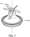
- the blade assembly and the blade holder comprises blade, blade shaft and coupling.
- the blades could be interchangeable based on the type of food to be processed.
- the jar collar comprises the button associated with a spring disposed at a first location and a second location, the first location being opposite to the second location and the stopper bracket comprises a plurality of horizontal packets and a plurality of vertical grooves configured such that, in operation, the plurality of horizontal packets aid in i) sliding the stopper bracket ii) keeping the stopper bracket in position when the button is not activated and the plurality of vertical grooves guide movement of the stopper bracket up/down.
- the jar collar is provided with a horizontal flange on which the blade holder could rest.
- the object of the invention is further realized by providing a base unit of a kitchen appliance comprising the improved blend and carry assembly.
- the base unit of the kitchen appliance is at least one of:
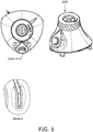
- Fig. 1 shows a prior art base unit 2000 of a kitchen appliance.
- the base unit 2000 could be that of a mixer grinder, juicer mixer grinder or a blender.
- Blend and carry is an add-on functionality that can be used with the base unit of the kitchen appliance.
- Blend and carry functionality is used for preparation of fruit and vegetable smoothies, shakes, ice crushing, sauces and dips, and meat mincing.
- the user has to fill the blender bottle with the required food ingredients, blend the food ingredients and change the blender blade with a lid to carry the blended food/drinks in hand. It is convenient to blend drinks and then take with oneself on one's commute.
- the base unit 2000 of the kitchen appliance is integrated with a micro-switch and a lever mechanism (Kindly refer to DETAIL A in Fig 1 ). This is provided for safety in order to avoid injury to the user that could arise due to accidental/unintentional access to the blade while the blade is rotating.
- the micro-switch and lever mechanism ensures that the motor does not operate unless the blender bottle encloses the blade completely.
- the disadvantage is the clearance gap (Kindly refer to DETAL A) between the lever and the base unit that houses the motor.
- the clearance gap between the lever and the body is required for the movement of the lever to activate the micro-switch.
- the blend and carry assembly 1000 comprises an inverted bottle 100 a blade assembly 200 and a blade holder 200A a jar collar 300 and a stopper bracket 500
- the jar collar and the stopper bracket ensures that the blade assembly is tightly coupled and completely enclosed within the inverted bottle. Further, the mounting of the inverted bottle on to the base motor power unit of the kitchen appliance is prevented if the blade assembly is not tightly coupled with the jar collar and the stopper bracket and is not completely enclosed within the inverted bottle.
- the disclosed mechanism will not allow coupling of the blade assembly to the motor unless the blade assembly is completely assembled with the jar collar and the stopper bracket. Hence, it prevents injury to the user due to accidental/unintentional access to the blade while in operation.
- the disclosed blend and carry assembly is provided with an inbuilt safety feature.
- the inbuilt safety feature avoids injury to the user due to accidental/unintentional access to the rotating blade.
- the disclosed blend and carry assembly to be mounted on the kitchen appliance does not require the clearance gap on the base unit 2000 that houses the motor. Due to the elimination of this clearance gap, there is no possibility of food ingredients, water, and dust getting accumulated. Hence, it overcomes hygiene issues. Further, there is no possibility of water getting into the motor. Hence, it could prevent situations of unsafe operation.
- the blade assembly 200 and the blade holder 200A can be integrated with the jar collar 300.
- the open end of the inverted bottle 100Q is integrated with small pitch thread 100A oriented in a first direction and big pitch thread 100B 1 , 100B 2 oriented in a second direction.
- the second direction is different from the first direction.
- the big pitch thread 100B 1 , 100B 2 are disposed above the small pitch thread 100A and configured to engage with the jar collar 300 and the stopper bracket 500.
- the small pitch thread and the big pitch thread are continuous threads.
- the big pitch threads are of different length and pitch compared to the small pitch thread so that it enables to pull the stopper bracket up.
- the small pitch thread helps to lock the jar collar and seal it with the blade holder.
- the small pitch thread further helps in activating the plurality of buttons and the associated plurality of springs to overcome the restriction on the movement of the stopper bracket.
- the big pitch thread helps to pull up the stopper bracket once the restriction is overcome by the small pitch thread and is assembled onto the jar collar.
- the combination of small pitch thread and the big pitch thread will ensure proper sealing and at the same time ensures proper coupling with the base unit. This is achieved by pulling up the stopper bracket vertically with the help of small pitch and big pitch thread. All these associated functions can be achieved by a single rotation of the inverted bottle.
- spring can be used instead of thread to push/pull the stopper bracket.
- press to lock or twist to lock mechanism could also be used.
- the big pitch thread 100B 1 , 100B 2 can be symmetrical or non-symmetrical.
- the pitch dimension of the small pitch thread 100A 1 is around 5 mm, the thread angle is around 25 degrees, the major diameter is around 90.3 mm and the minor diameter is around 84.5 mm.
- the small pitch thread helps to activate the button 300A 1 300A 2 which in turn will allow the vertical movement of the stopper bracket. Further, it will help in tightly sealing the jar collar.
- the pitch dimension of the big pitch thread 100B 1 , 100B 2 is around 48 mm, the thread angle is around 19 degrees, the major diameter is around 93 mm and the minor diameter is around 84.5 mm.
- the big pitch thread helps to move the stopper bracket after the activation of the button 300A 1 300A 2 .
- the groove cross section of the small pitch thread 100A 1 and the big pitch thread 100B 1 , 100B 2 is at least one of unified ( Fig. 5a ), metric ( Fig. 5b ), square ( Fig. 5c ), ACME ( Fig. 5d ) and Buttress ( Fig. 5e ).
- unified and metric is suited for general conditions
- square is suited for power transmission
- buttress is suited to handle heavy forces in one direction.
- the small pitch thread 100A and the big pitch thread 100B 1 , 100B 2 are right handed threads.
- the small pitch thread lock and engage the inverted bottle to the jar collar and activates the button 300A 1 , 300A 2 enabling the big pitch thread to push/pull the stopper bracket.
- grooves 100g 1 , 100g 2 are provided on the exterior surface of the inverted bottle for convenient grip while carrying and locking the bottle on to the jar collar.
- the small pitch thread are arranged to seal the inverted bottle and activate the button 300A 1 , 300A 2 and the big pitch threads are used to pull the stopper bracket.
- a single thread cycle enables both the functions namely sealing the inverted bottle and pulling the stopper bracket in the upward direction allowing the mounting of the jar collar onto the base unit.
- the blade assembly 200 and the blade holder 200A comprises blade, blade shaft and coupling.
- the blades are interchangeable based on the type of food processing required.
- the blade assembly 200 and the blade holder 200A can be integrated with the jar collar 300.
- the jar collar 300 comprises button 300A 1 associated with a spring 300B 1 disposed at a first location L 1 , a button 300 A 2 and a spring 300B 2 disposed at a second location L 2 , the first location L 1 being opposite to the second location L 2 .
- the spring could be disc spring, conical spring, plastic spring that can withstand or retain the load.
- the stopper bracket 500 comprises a plurality of horizontal packets hgi, hg 2 , and a plurality of vertical grooves vl 1 , vl 2 , vl 2 , vl 4 configured such that, in operation, the plurality of horizontal packets aid in i) sliding the stopper bracket ii) keeping the stopper bracket in position when the button is not activated and the plurality of vertical grooves guide the movement of the stopper bracket up/down.
- the jar collar is provided with a horizontal flange on which the blade holder could rest.
- the base unit 2000 of the kitchen appliance could comprise the disclosed blend and carry assembly 1000.
- the base unit could be at least one of mixer grinder, juicer mixer grinder or blender.
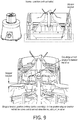
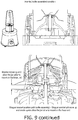
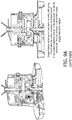
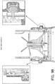
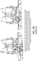
- Fig. 9 , Fig. 9A and Fig. 9B illustrates construction, assembly, usage and working mode of the disclosed blend and carry assembly.
- the open end of the inverted bottle 100Q is integrated with two different pitch threads, namely small pitch threads 100A and big pitch thread 100B 1 , 100B 2 oriented differently.
- the small pitch thread is used to assemble the inverted bottle with the jar collar by simple rotation.
- the small pitch thread is used to push the button 300A 1 300A 2 and the spring 300B 1 300 B 2 sideways.
- Above the small pitch thread the big pitch thread is provided to engage with the stopper bracket 500. Due to this engagement, the stopper bracket is pulled up or pushed down to initial position when the inverted bottle is assembled or disassembled on to the jar collar 300 respectively.
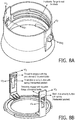
- the stopper bracket 500 is assembled onto the jar collar using the vertical grooves vl 1 , vl 2 , vl 3 , vl 4 . (Refer to Fig. 8A, 8B ).
- the stopper bracket will be at the bottom position (Refer to Fig. 9 , Fig. 9A and Fig. 9B ) initially when the inverted bottle is not locked with the jar collar. It is held in the bottom position by the buttons 300A 1 , 300A 2 .
- the stopper bracket will physically block the access to the jar collar 300 and not allow the user to assemble it.
- buttons 300A 1 , 300A 2 along with the springs 300B 1 , 300B 2 act as a restriction for the stopper bracket.
- the buttons 300A 1 , 300A 2 are fixed onto the jar collar along with spring 300B 1 , 300B 2 and are activated by the small pitch thread 100A of the inverted bottle while tightening.
- the spring on the other side of the button is used to return it to the original position once the inverted bottle is removed.
- buttons 300A 1 , 300A 2 are assembled on to the jar collar using snap locks to retain the position against the spring force.
- the button holds the stopper bracket in the bottom position at the open condition and will allow upward movement only when the inverted bottle is assembled.
- Jar collar holds the buttons 300A 1 , 300A 2 and the springs 300B 1 , 300B 2 in two locations opposite to each other.
- the horizontal packets hgi, hg 2 aid in sliding the stopper bracket and in keeping the stopper bracket in position when the button is not activated (i.e., normal condition).
- the vertical grooves vl 1 , vl 2 , vl 3 vl 4 are provided to support the stopper bracket while moving up/down.
- the jar collar is open at both the ends. One end of the opening has thread to assemble with the inverted bottle and the other end has a feature to lock (one has to rotate to lock) on to the base unit of the kitchen appliance.
- a horizontal flange is provided to rest the blade holder assembly. Based on the position, partial coupling is avoided even if the user tries to assemble the jar collar and the blade alone.
- the disclosed blend and carry bottle assembly does not require any slot/opening on the base unit. Therefore, there is no clearance gap and spillage of the food ingredients, water or dust does not create any hygiene issues. Hygiene issues could be prevented.
- well groove type lock or outer lock type (exposed coupler) interface could be used to assemble the blend and carry bottle on to the base unit along with optimized jar collar.
- buttons instead of two buttons a plurality of buttons could be used to perform the function.
- the guiding cross section/location of grooves for the stopper bracket profile can be in any form
- the disclosed blend and carry assembly can be used as an add on attachment on the existing base unit of mixer grinder, juicer mixer grinders, that do not support micro-switch and lever integrated mechanism.
- the kitchen appliances occupy space. In the present day mode of living with small apartments or houses in which there is dearth of storage space, it has become increasingly necessary to use compact kitchen appliance whereby one kitchen appliance can do the work of several kitchen appliances.
- Customers can purchase the blend and carry attachment as a separate unit and start using it on their existing base unit instead of going in for a new standalone blender unit. It is affordable and saves space as the same base unit of mixer grinder/juicer mixer grinder can be used to realize blending functionality. It offers multi functionality and has economic significance.
- the disclosed blend and carry assembly makes efficient use of space and accommodates dual functions namely grinding and mixing functions.
- the disclosed blend and carry assembly is compact in construction and solves the problem of space requirement by providing both functions in one compact kitchen appliance along with an add on blend and carry assembly.
- the disclosed blend and carry assembly is easy to handle, clean, and maintain.
- the home maker has to pay individual attention to each one of them namely a blender and a mixer grinder or a juicer mixer grinder. Handling two different individual kitchen appliances could be difficult.
- the disclosed blend and carry assembly is an add on attachment and there is no need for a separate base unit. Hence, handling becomes easy.
Landscapes
- Engineering & Computer Science (AREA)
- Mechanical Engineering (AREA)
- Food Science & Technology (AREA)
- Food-Manufacturing Devices (AREA)
Priority Applications (1)
| Application Number | Priority Date | Filing Date | Title |
|---|---|---|---|
| EP19178335.6A EP3747324A1 (fr) | 2019-06-05 | 2019-06-05 | Ensemble de mélange et de transport pour un appareil de cuisine |
Applications Claiming Priority (1)
| Application Number | Priority Date | Filing Date | Title |
|---|---|---|---|
| EP19178335.6A EP3747324A1 (fr) | 2019-06-05 | 2019-06-05 | Ensemble de mélange et de transport pour un appareil de cuisine |
Publications (1)
| Publication Number | Publication Date |
|---|---|
| EP3747324A1 true EP3747324A1 (fr) | 2020-12-09 |
Family
ID=66770297
Family Applications (1)
| Application Number | Title | Priority Date | Filing Date |
|---|---|---|---|
| EP19178335.6A Withdrawn EP3747324A1 (fr) | 2019-06-05 | 2019-06-05 | Ensemble de mélange et de transport pour un appareil de cuisine |
Country Status (1)
| Country | Link |
|---|---|
| EP (1) | EP3747324A1 (fr) |
Citations (3)
| Publication number | Priority date | Publication date | Assignee | Title |
|---|---|---|---|---|
| US5338111A (en) * | 1992-04-30 | 1994-08-16 | Moulinex (Societe Anonyme) | Kitchen appliance, such as a mixer provided with a safety retractable detent |
| US7220049B2 (en) | 2004-08-09 | 2007-05-22 | Ming-Tsung Lee | Blender with a safe starting function |
| US20120213029A1 (en) * | 2009-08-26 | 2012-08-23 | Frxsh Ag | Apparatus and method for mixing of a material to be mixed |
-
2019
- 2019-06-05 EP EP19178335.6A patent/EP3747324A1/fr not_active Withdrawn
Patent Citations (3)
| Publication number | Priority date | Publication date | Assignee | Title |
|---|---|---|---|---|
| US5338111A (en) * | 1992-04-30 | 1994-08-16 | Moulinex (Societe Anonyme) | Kitchen appliance, such as a mixer provided with a safety retractable detent |
| US7220049B2 (en) | 2004-08-09 | 2007-05-22 | Ming-Tsung Lee | Blender with a safe starting function |
| US20120213029A1 (en) * | 2009-08-26 | 2012-08-23 | Frxsh Ag | Apparatus and method for mixing of a material to be mixed |
Similar Documents
| Publication | Publication Date | Title |
|---|---|---|
| US9198540B2 (en) | Food processor with locking bail handle | |
| KR102090500B1 (ko) | 식품 가공기 | |
| US7871195B2 (en) | Mixing device configured to blend food | |
| US10893775B2 (en) | Blender container with latch release | |
| JP5431957B2 (ja) | 食物処理システム | |
| US7520453B2 (en) | Safety actuator for a food processor having a visual indication | |
| US20200237159A1 (en) | Blender | |
| US20130233952A1 (en) | Kitchen Appliance for Processing Foodstuff and Method of Operating Same | |
| US9192264B2 (en) | Food processor | |
| US20130264405A1 (en) | Food processor | |
| US20080212403A1 (en) | Blender having an invertable jar | |
| US11344157B2 (en) | Blender and food processor combination with safety features | |
| RU2578585C2 (ru) | Инструмент для приводимого двигателем кухонного прибора | |
| JP6626044B2 (ja) | 調理器 | |
| EP3747324A1 (fr) | Ensemble de mélange et de transport pour un appareil de cuisine | |
| CN111246785B (zh) | 用于搅拌或粉碎食物的器具 | |
| JP2017520333A (ja) | 食品加工用調理器具 | |
| EP3845101B1 (fr) | Récipient ayant une poignée pour un appareil de cuisine | |
| EP3766394B1 (fr) | Récipient destiné à un appareil de cuisine | |
| EP3733033A1 (fr) | Dispositif de couvercle doté d'un systeme d'engrenages pour processeur alimentaire | |
| KR20150141849A (ko) | 자동회전 머그컵 | |
| CN217524616U (zh) | 一种烹饪锅具 | |
| US20230218116A1 (en) | Blender/Juicer Appliance With Safety Latch Arrangement | |
| EP4042915B1 (fr) | Appareil modulaire de cuisine portable | |
| KR101462667B1 (ko) | 수동 음식 재료 다짐기 |
Legal Events
| Date | Code | Title | Description |
|---|---|---|---|
| PUAI | Public reference made under article 153(3) epc to a published international application that has entered the european phase |
Free format text: ORIGINAL CODE: 0009012 |
|
| STAA | Information on the status of an ep patent application or granted ep patent |
Free format text: STATUS: THE APPLICATION HAS BEEN PUBLISHED |
|
| AK | Designated contracting states |
Kind code of ref document: A1 Designated state(s): AL AT BE BG CH CY CZ DE DK EE ES FI FR GB GR HR HU IE IS IT LI LT LU LV MC MK MT NL NO PL PT RO RS SE SI SK SM TR |
|
| AX | Request for extension of the european patent |
Extension state: BA ME |
|
| STAA | Information on the status of an ep patent application or granted ep patent |
Free format text: STATUS: REQUEST FOR EXAMINATION WAS MADE |
|
| 17P | Request for examination filed |
Effective date: 20210609 |
|
| RBV | Designated contracting states (corrected) |
Designated state(s): AL AT BE BG CH CY CZ DE DK EE ES FI FR GB GR HR HU IE IS IT LI LT LU LV MC MK MT NL NO PL PT RO RS SE SI SK SM TR |
|
| STAA | Information on the status of an ep patent application or granted ep patent |
Free format text: STATUS: THE APPLICATION IS DEEMED TO BE WITHDRAWN |
|
| 18D | Application deemed to be withdrawn |
Effective date: 20210610 |