EP3747480B1 - Fabrication d'articles revêtus - Google Patents
Fabrication d'articles revêtus Download PDFInfo
- Publication number
- EP3747480B1 EP3747480B1 EP20178402.2A EP20178402A EP3747480B1 EP 3747480 B1 EP3747480 B1 EP 3747480B1 EP 20178402 A EP20178402 A EP 20178402A EP 3747480 B1 EP3747480 B1 EP 3747480B1
- Authority
- EP
- European Patent Office
- Prior art keywords
- substrate
- deposition
- reaction space
- fluid
- precursor
- Prior art date
- Legal status (The legal status is an assumption and is not a legal conclusion. Google has not performed a legal analysis and makes no representation as to the accuracy of the status listed.)
- Active
Links
Images

Classifications
-
- C—CHEMISTRY; METALLURGY
- C23—COATING METALLIC MATERIAL; COATING MATERIAL WITH METALLIC MATERIAL; CHEMICAL SURFACE TREATMENT; DIFFUSION TREATMENT OF METALLIC MATERIAL; COATING BY VACUUM EVAPORATION, BY SPUTTERING, BY ION IMPLANTATION OR BY CHEMICAL VAPOUR DEPOSITION, IN GENERAL; INHIBITING CORROSION OF METALLIC MATERIAL OR INCRUSTATION IN GENERAL
- C23C—COATING METALLIC MATERIAL; COATING MATERIAL WITH METALLIC MATERIAL; SURFACE TREATMENT OF METALLIC MATERIAL BY DIFFUSION INTO THE SURFACE, BY CHEMICAL CONVERSION OR SUBSTITUTION; COATING BY VACUUM EVAPORATION, BY SPUTTERING, BY ION IMPLANTATION OR BY CHEMICAL VAPOUR DEPOSITION, IN GENERAL
- C23C16/00—Chemical coating by decomposition of gaseous compounds, without leaving reaction products of surface material in the coating, i.e. chemical vapour deposition [CVD] processes
- C23C16/22—Chemical coating by decomposition of gaseous compounds, without leaving reaction products of surface material in the coating, i.e. chemical vapour deposition [CVD] processes characterised by the deposition of inorganic material, other than metallic material
- C23C16/30—Deposition of compounds, mixtures or solid solutions, e.g. borides, carbides, nitrides
- C23C16/34—Nitrides
-
- C—CHEMISTRY; METALLURGY
- C23—COATING METALLIC MATERIAL; COATING MATERIAL WITH METALLIC MATERIAL; CHEMICAL SURFACE TREATMENT; DIFFUSION TREATMENT OF METALLIC MATERIAL; COATING BY VACUUM EVAPORATION, BY SPUTTERING, BY ION IMPLANTATION OR BY CHEMICAL VAPOUR DEPOSITION, IN GENERAL; INHIBITING CORROSION OF METALLIC MATERIAL OR INCRUSTATION IN GENERAL
- C23C—COATING METALLIC MATERIAL; COATING MATERIAL WITH METALLIC MATERIAL; SURFACE TREATMENT OF METALLIC MATERIAL BY DIFFUSION INTO THE SURFACE, BY CHEMICAL CONVERSION OR SUBSTITUTION; COATING BY VACUUM EVAPORATION, BY SPUTTERING, BY ION IMPLANTATION OR BY CHEMICAL VAPOUR DEPOSITION, IN GENERAL
- C23C16/00—Chemical coating by decomposition of gaseous compounds, without leaving reaction products of surface material in the coating, i.e. chemical vapour deposition [CVD] processes
- C23C16/04—Coating on selected surface areas, e.g. using masks
- C23C16/045—Coating cavities or hollow spaces, e.g. interior of tubes; Infiltration of porous substrates
-
- A—HUMAN NECESSITIES
- A61—MEDICAL OR VETERINARY SCIENCE; HYGIENE
- A61F—FILTERS IMPLANTABLE INTO BLOOD VESSELS; PROSTHESES; DEVICES PROVIDING PATENCY TO, OR PREVENTING COLLAPSING OF, TUBULAR STRUCTURES OF THE BODY, e.g. STENTS; ORTHOPAEDIC, NURSING OR CONTRACEPTIVE DEVICES; FOMENTATION; TREATMENT OR PROTECTION OF EYES OR EARS; BANDAGES, DRESSINGS OR ABSORBENT PADS; FIRST-AID KITS
- A61F2/00—Filters implantable into blood vessels; Prostheses, i.e. artificial substitutes or replacements for parts of the body; Appliances for connecting them with the body; Devices providing patency to, or preventing collapsing of, tubular structures of the body, e.g. stents
-
- A—HUMAN NECESSITIES
- A61—MEDICAL OR VETERINARY SCIENCE; HYGIENE
- A61F—FILTERS IMPLANTABLE INTO BLOOD VESSELS; PROSTHESES; DEVICES PROVIDING PATENCY TO, OR PREVENTING COLLAPSING OF, TUBULAR STRUCTURES OF THE BODY, e.g. STENTS; ORTHOPAEDIC, NURSING OR CONTRACEPTIVE DEVICES; FOMENTATION; TREATMENT OR PROTECTION OF EYES OR EARS; BANDAGES, DRESSINGS OR ABSORBENT PADS; FIRST-AID KITS
- A61F2/00—Filters implantable into blood vessels; Prostheses, i.e. artificial substitutes or replacements for parts of the body; Appliances for connecting them with the body; Devices providing patency to, or preventing collapsing of, tubular structures of the body, e.g. stents
- A61F2/82—Devices providing patency to, or preventing collapsing of, tubular structures of the body, e.g. stents
- A61F2/86—Stents in a form characterised by the wire-like elements; Stents in the form characterised by a net-like or mesh-like structure
- A61F2/90—Stents in a form characterised by the wire-like elements; Stents in the form characterised by a net-like or mesh-like structure characterised by a net-like or mesh-like structure
-
- A—HUMAN NECESSITIES
- A61—MEDICAL OR VETERINARY SCIENCE; HYGIENE
- A61L—METHODS OR APPARATUS FOR STERILISING MATERIALS OR OBJECTS IN GENERAL; DISINFECTION, STERILISATION OR DEODORISATION OF AIR; CHEMICAL ASPECTS OF BANDAGES, DRESSINGS, ABSORBENT PADS OR SURGICAL ARTICLES; MATERIALS FOR BANDAGES, DRESSINGS, ABSORBENT PADS OR SURGICAL ARTICLES
- A61L29/00—Materials for catheters, medical tubing, cannulae, or endoscopes or for coating catheters
- A61L29/08—Materials for coatings
- A61L29/10—Inorganic materials
- A61L29/106—Inorganic materials other than carbon
-
- A—HUMAN NECESSITIES
- A61—MEDICAL OR VETERINARY SCIENCE; HYGIENE
- A61L—METHODS OR APPARATUS FOR STERILISING MATERIALS OR OBJECTS IN GENERAL; DISINFECTION, STERILISATION OR DEODORISATION OF AIR; CHEMICAL ASPECTS OF BANDAGES, DRESSINGS, ABSORBENT PADS OR SURGICAL ARTICLES; MATERIALS FOR BANDAGES, DRESSINGS, ABSORBENT PADS OR SURGICAL ARTICLES
- A61L29/00—Materials for catheters, medical tubing, cannulae, or endoscopes or for coating catheters
- A61L29/14—Materials characterised by their function or physical properties, e.g. lubricating compositions
-
- A—HUMAN NECESSITIES
- A61—MEDICAL OR VETERINARY SCIENCE; HYGIENE
- A61L—METHODS OR APPARATUS FOR STERILISING MATERIALS OR OBJECTS IN GENERAL; DISINFECTION, STERILISATION OR DEODORISATION OF AIR; CHEMICAL ASPECTS OF BANDAGES, DRESSINGS, ABSORBENT PADS OR SURGICAL ARTICLES; MATERIALS FOR BANDAGES, DRESSINGS, ABSORBENT PADS OR SURGICAL ARTICLES
- A61L31/00—Materials for other surgical articles, e.g. stents, stent-grafts, shunts, surgical drapes, guide wires, materials for adhesion prevention, occluding devices, surgical gloves, tissue fixation devices
- A61L31/08—Materials for coatings
- A61L31/082—Inorganic materials
- A61L31/088—Other specific inorganic materials not covered by A61L31/084 or A61L31/086
-
- A—HUMAN NECESSITIES
- A61—MEDICAL OR VETERINARY SCIENCE; HYGIENE
- A61M—DEVICES FOR INTRODUCING MEDIA INTO, OR ONTO, THE BODY; DEVICES FOR TRANSDUCING BODY MEDIA OR FOR TAKING MEDIA FROM THE BODY; DEVICES FOR PRODUCING OR ENDING SLEEP OR STUPOR
- A61M25/00—Catheters; Hollow probes
- A61M25/0009—Making of catheters or other medical or surgical tubes
-
- C—CHEMISTRY; METALLURGY
- C23—COATING METALLIC MATERIAL; COATING MATERIAL WITH METALLIC MATERIAL; CHEMICAL SURFACE TREATMENT; DIFFUSION TREATMENT OF METALLIC MATERIAL; COATING BY VACUUM EVAPORATION, BY SPUTTERING, BY ION IMPLANTATION OR BY CHEMICAL VAPOUR DEPOSITION, IN GENERAL; INHIBITING CORROSION OF METALLIC MATERIAL OR INCRUSTATION IN GENERAL
- C23C—COATING METALLIC MATERIAL; COATING MATERIAL WITH METALLIC MATERIAL; SURFACE TREATMENT OF METALLIC MATERIAL BY DIFFUSION INTO THE SURFACE, BY CHEMICAL CONVERSION OR SUBSTITUTION; COATING BY VACUUM EVAPORATION, BY SPUTTERING, BY ION IMPLANTATION OR BY CHEMICAL VAPOUR DEPOSITION, IN GENERAL
- C23C16/00—Chemical coating by decomposition of gaseous compounds, without leaving reaction products of surface material in the coating, i.e. chemical vapour deposition [CVD] processes
- C23C16/04—Coating on selected surface areas, e.g. using masks
-
- C—CHEMISTRY; METALLURGY
- C23—COATING METALLIC MATERIAL; COATING MATERIAL WITH METALLIC MATERIAL; CHEMICAL SURFACE TREATMENT; DIFFUSION TREATMENT OF METALLIC MATERIAL; COATING BY VACUUM EVAPORATION, BY SPUTTERING, BY ION IMPLANTATION OR BY CHEMICAL VAPOUR DEPOSITION, IN GENERAL; INHIBITING CORROSION OF METALLIC MATERIAL OR INCRUSTATION IN GENERAL
- C23C—COATING METALLIC MATERIAL; COATING MATERIAL WITH METALLIC MATERIAL; SURFACE TREATMENT OF METALLIC MATERIAL BY DIFFUSION INTO THE SURFACE, BY CHEMICAL CONVERSION OR SUBSTITUTION; COATING BY VACUUM EVAPORATION, BY SPUTTERING, BY ION IMPLANTATION OR BY CHEMICAL VAPOUR DEPOSITION, IN GENERAL
- C23C16/00—Chemical coating by decomposition of gaseous compounds, without leaving reaction products of surface material in the coating, i.e. chemical vapour deposition [CVD] processes
- C23C16/22—Chemical coating by decomposition of gaseous compounds, without leaving reaction products of surface material in the coating, i.e. chemical vapour deposition [CVD] processes characterised by the deposition of inorganic material, other than metallic material
- C23C16/30—Deposition of compounds, mixtures or solid solutions, e.g. borides, carbides, nitrides
- C23C16/308—Oxynitrides
-
- C—CHEMISTRY; METALLURGY
- C23—COATING METALLIC MATERIAL; COATING MATERIAL WITH METALLIC MATERIAL; CHEMICAL SURFACE TREATMENT; DIFFUSION TREATMENT OF METALLIC MATERIAL; COATING BY VACUUM EVAPORATION, BY SPUTTERING, BY ION IMPLANTATION OR BY CHEMICAL VAPOUR DEPOSITION, IN GENERAL; INHIBITING CORROSION OF METALLIC MATERIAL OR INCRUSTATION IN GENERAL
- C23C—COATING METALLIC MATERIAL; COATING MATERIAL WITH METALLIC MATERIAL; SURFACE TREATMENT OF METALLIC MATERIAL BY DIFFUSION INTO THE SURFACE, BY CHEMICAL CONVERSION OR SUBSTITUTION; COATING BY VACUUM EVAPORATION, BY SPUTTERING, BY ION IMPLANTATION OR BY CHEMICAL VAPOUR DEPOSITION, IN GENERAL
- C23C16/00—Chemical coating by decomposition of gaseous compounds, without leaving reaction products of surface material in the coating, i.e. chemical vapour deposition [CVD] processes
- C23C16/22—Chemical coating by decomposition of gaseous compounds, without leaving reaction products of surface material in the coating, i.e. chemical vapour deposition [CVD] processes characterised by the deposition of inorganic material, other than metallic material
- C23C16/30—Deposition of compounds, mixtures or solid solutions, e.g. borides, carbides, nitrides
- C23C16/40—Oxides
- C23C16/405—Oxides of refractory metals or yttrium
-
- C—CHEMISTRY; METALLURGY
- C23—COATING METALLIC MATERIAL; COATING MATERIAL WITH METALLIC MATERIAL; CHEMICAL SURFACE TREATMENT; DIFFUSION TREATMENT OF METALLIC MATERIAL; COATING BY VACUUM EVAPORATION, BY SPUTTERING, BY ION IMPLANTATION OR BY CHEMICAL VAPOUR DEPOSITION, IN GENERAL; INHIBITING CORROSION OF METALLIC MATERIAL OR INCRUSTATION IN GENERAL
- C23C—COATING METALLIC MATERIAL; COATING MATERIAL WITH METALLIC MATERIAL; SURFACE TREATMENT OF METALLIC MATERIAL BY DIFFUSION INTO THE SURFACE, BY CHEMICAL CONVERSION OR SUBSTITUTION; COATING BY VACUUM EVAPORATION, BY SPUTTERING, BY ION IMPLANTATION OR BY CHEMICAL VAPOUR DEPOSITION, IN GENERAL
- C23C16/00—Chemical coating by decomposition of gaseous compounds, without leaving reaction products of surface material in the coating, i.e. chemical vapour deposition [CVD] processes
- C23C16/44—Chemical coating by decomposition of gaseous compounds, without leaving reaction products of surface material in the coating, i.e. chemical vapour deposition [CVD] processes characterised by the method of coating
- C23C16/4401—Means for minimising impurities, e.g. dust, moisture or residual gas, in the reaction chamber
- C23C16/4408—Means for minimising impurities, e.g. dust, moisture or residual gas, in the reaction chamber by purging residual gases from the reaction chamber or gas lines
-
- C—CHEMISTRY; METALLURGY
- C23—COATING METALLIC MATERIAL; COATING MATERIAL WITH METALLIC MATERIAL; CHEMICAL SURFACE TREATMENT; DIFFUSION TREATMENT OF METALLIC MATERIAL; COATING BY VACUUM EVAPORATION, BY SPUTTERING, BY ION IMPLANTATION OR BY CHEMICAL VAPOUR DEPOSITION, IN GENERAL; INHIBITING CORROSION OF METALLIC MATERIAL OR INCRUSTATION IN GENERAL
- C23C—COATING METALLIC MATERIAL; COATING MATERIAL WITH METALLIC MATERIAL; SURFACE TREATMENT OF METALLIC MATERIAL BY DIFFUSION INTO THE SURFACE, BY CHEMICAL CONVERSION OR SUBSTITUTION; COATING BY VACUUM EVAPORATION, BY SPUTTERING, BY ION IMPLANTATION OR BY CHEMICAL VAPOUR DEPOSITION, IN GENERAL
- C23C16/00—Chemical coating by decomposition of gaseous compounds, without leaving reaction products of surface material in the coating, i.e. chemical vapour deposition [CVD] processes
- C23C16/44—Chemical coating by decomposition of gaseous compounds, without leaving reaction products of surface material in the coating, i.e. chemical vapour deposition [CVD] processes characterised by the method of coating
- C23C16/455—Chemical coating by decomposition of gaseous compounds, without leaving reaction products of surface material in the coating, i.e. chemical vapour deposition [CVD] processes characterised by the method of coating characterised by the method used for introducing gases into reaction chamber or for modifying gas flows in reaction chamber
- C23C16/45519—Inert gas curtains
-
- C—CHEMISTRY; METALLURGY
- C23—COATING METALLIC MATERIAL; COATING MATERIAL WITH METALLIC MATERIAL; CHEMICAL SURFACE TREATMENT; DIFFUSION TREATMENT OF METALLIC MATERIAL; COATING BY VACUUM EVAPORATION, BY SPUTTERING, BY ION IMPLANTATION OR BY CHEMICAL VAPOUR DEPOSITION, IN GENERAL; INHIBITING CORROSION OF METALLIC MATERIAL OR INCRUSTATION IN GENERAL
- C23C—COATING METALLIC MATERIAL; COATING MATERIAL WITH METALLIC MATERIAL; SURFACE TREATMENT OF METALLIC MATERIAL BY DIFFUSION INTO THE SURFACE, BY CHEMICAL CONVERSION OR SUBSTITUTION; COATING BY VACUUM EVAPORATION, BY SPUTTERING, BY ION IMPLANTATION OR BY CHEMICAL VAPOUR DEPOSITION, IN GENERAL
- C23C16/00—Chemical coating by decomposition of gaseous compounds, without leaving reaction products of surface material in the coating, i.e. chemical vapour deposition [CVD] processes
- C23C16/44—Chemical coating by decomposition of gaseous compounds, without leaving reaction products of surface material in the coating, i.e. chemical vapour deposition [CVD] processes characterised by the method of coating
- C23C16/455—Chemical coating by decomposition of gaseous compounds, without leaving reaction products of surface material in the coating, i.e. chemical vapour deposition [CVD] processes characterised by the method of coating characterised by the method used for introducing gases into reaction chamber or for modifying gas flows in reaction chamber
- C23C16/45523—Pulsed gas flow or change of composition over time
- C23C16/45525—Atomic layer deposition [ALD]
-
- C—CHEMISTRY; METALLURGY
- C23—COATING METALLIC MATERIAL; COATING MATERIAL WITH METALLIC MATERIAL; CHEMICAL SURFACE TREATMENT; DIFFUSION TREATMENT OF METALLIC MATERIAL; COATING BY VACUUM EVAPORATION, BY SPUTTERING, BY ION IMPLANTATION OR BY CHEMICAL VAPOUR DEPOSITION, IN GENERAL; INHIBITING CORROSION OF METALLIC MATERIAL OR INCRUSTATION IN GENERAL
- C23C—COATING METALLIC MATERIAL; COATING MATERIAL WITH METALLIC MATERIAL; SURFACE TREATMENT OF METALLIC MATERIAL BY DIFFUSION INTO THE SURFACE, BY CHEMICAL CONVERSION OR SUBSTITUTION; COATING BY VACUUM EVAPORATION, BY SPUTTERING, BY ION IMPLANTATION OR BY CHEMICAL VAPOUR DEPOSITION, IN GENERAL
- C23C16/00—Chemical coating by decomposition of gaseous compounds, without leaving reaction products of surface material in the coating, i.e. chemical vapour deposition [CVD] processes
- C23C16/44—Chemical coating by decomposition of gaseous compounds, without leaving reaction products of surface material in the coating, i.e. chemical vapour deposition [CVD] processes characterised by the method of coating
- C23C16/455—Chemical coating by decomposition of gaseous compounds, without leaving reaction products of surface material in the coating, i.e. chemical vapour deposition [CVD] processes characterised by the method of coating characterised by the method used for introducing gases into reaction chamber or for modifying gas flows in reaction chamber
- C23C16/45523—Pulsed gas flow or change of composition over time
- C23C16/45525—Atomic layer deposition [ALD]
- C23C16/45544—Atomic layer deposition [ALD] characterized by the apparatus
-
- C—CHEMISTRY; METALLURGY
- C23—COATING METALLIC MATERIAL; COATING MATERIAL WITH METALLIC MATERIAL; CHEMICAL SURFACE TREATMENT; DIFFUSION TREATMENT OF METALLIC MATERIAL; COATING BY VACUUM EVAPORATION, BY SPUTTERING, BY ION IMPLANTATION OR BY CHEMICAL VAPOUR DEPOSITION, IN GENERAL; INHIBITING CORROSION OF METALLIC MATERIAL OR INCRUSTATION IN GENERAL
- C23C—COATING METALLIC MATERIAL; COATING MATERIAL WITH METALLIC MATERIAL; SURFACE TREATMENT OF METALLIC MATERIAL BY DIFFUSION INTO THE SURFACE, BY CHEMICAL CONVERSION OR SUBSTITUTION; COATING BY VACUUM EVAPORATION, BY SPUTTERING, BY ION IMPLANTATION OR BY CHEMICAL VAPOUR DEPOSITION, IN GENERAL
- C23C16/00—Chemical coating by decomposition of gaseous compounds, without leaving reaction products of surface material in the coating, i.e. chemical vapour deposition [CVD] processes
- C23C16/44—Chemical coating by decomposition of gaseous compounds, without leaving reaction products of surface material in the coating, i.e. chemical vapour deposition [CVD] processes characterised by the method of coating
- C23C16/455—Chemical coating by decomposition of gaseous compounds, without leaving reaction products of surface material in the coating, i.e. chemical vapour deposition [CVD] processes characterised by the method of coating characterised by the method used for introducing gases into reaction chamber or for modifying gas flows in reaction chamber
- C23C16/45523—Pulsed gas flow or change of composition over time
- C23C16/45525—Atomic layer deposition [ALD]
- C23C16/45553—Atomic layer deposition [ALD] characterized by the use of precursors specially adapted for ALD
-
- C—CHEMISTRY; METALLURGY
- C23—COATING METALLIC MATERIAL; COATING MATERIAL WITH METALLIC MATERIAL; CHEMICAL SURFACE TREATMENT; DIFFUSION TREATMENT OF METALLIC MATERIAL; COATING BY VACUUM EVAPORATION, BY SPUTTERING, BY ION IMPLANTATION OR BY CHEMICAL VAPOUR DEPOSITION, IN GENERAL; INHIBITING CORROSION OF METALLIC MATERIAL OR INCRUSTATION IN GENERAL
- C23C—COATING METALLIC MATERIAL; COATING MATERIAL WITH METALLIC MATERIAL; SURFACE TREATMENT OF METALLIC MATERIAL BY DIFFUSION INTO THE SURFACE, BY CHEMICAL CONVERSION OR SUBSTITUTION; COATING BY VACUUM EVAPORATION, BY SPUTTERING, BY ION IMPLANTATION OR BY CHEMICAL VAPOUR DEPOSITION, IN GENERAL
- C23C16/00—Chemical coating by decomposition of gaseous compounds, without leaving reaction products of surface material in the coating, i.e. chemical vapour deposition [CVD] processes
- C23C16/44—Chemical coating by decomposition of gaseous compounds, without leaving reaction products of surface material in the coating, i.e. chemical vapour deposition [CVD] processes characterised by the method of coating
- C23C16/455—Chemical coating by decomposition of gaseous compounds, without leaving reaction products of surface material in the coating, i.e. chemical vapour deposition [CVD] processes characterised by the method of coating characterised by the method used for introducing gases into reaction chamber or for modifying gas flows in reaction chamber
- C23C16/45523—Pulsed gas flow or change of composition over time
- C23C16/45525—Atomic layer deposition [ALD]
- C23C16/45555—Atomic layer deposition [ALD] applied in non-semiconductor technology
-
- C—CHEMISTRY; METALLURGY
- C23—COATING METALLIC MATERIAL; COATING MATERIAL WITH METALLIC MATERIAL; CHEMICAL SURFACE TREATMENT; DIFFUSION TREATMENT OF METALLIC MATERIAL; COATING BY VACUUM EVAPORATION, BY SPUTTERING, BY ION IMPLANTATION OR BY CHEMICAL VAPOUR DEPOSITION, IN GENERAL; INHIBITING CORROSION OF METALLIC MATERIAL OR INCRUSTATION IN GENERAL
- C23C—COATING METALLIC MATERIAL; COATING MATERIAL WITH METALLIC MATERIAL; SURFACE TREATMENT OF METALLIC MATERIAL BY DIFFUSION INTO THE SURFACE, BY CHEMICAL CONVERSION OR SUBSTITUTION; COATING BY VACUUM EVAPORATION, BY SPUTTERING, BY ION IMPLANTATION OR BY CHEMICAL VAPOUR DEPOSITION, IN GENERAL
- C23C16/00—Chemical coating by decomposition of gaseous compounds, without leaving reaction products of surface material in the coating, i.e. chemical vapour deposition [CVD] processes
- C23C16/44—Chemical coating by decomposition of gaseous compounds, without leaving reaction products of surface material in the coating, i.e. chemical vapour deposition [CVD] processes characterised by the method of coating
- C23C16/455—Chemical coating by decomposition of gaseous compounds, without leaving reaction products of surface material in the coating, i.e. chemical vapour deposition [CVD] processes characterised by the method of coating characterised by the method used for introducing gases into reaction chamber or for modifying gas flows in reaction chamber
- C23C16/45563—Gas nozzles
- C23C16/45568—Porous nozzles
-
- C—CHEMISTRY; METALLURGY
- C23—COATING METALLIC MATERIAL; COATING MATERIAL WITH METALLIC MATERIAL; CHEMICAL SURFACE TREATMENT; DIFFUSION TREATMENT OF METALLIC MATERIAL; COATING BY VACUUM EVAPORATION, BY SPUTTERING, BY ION IMPLANTATION OR BY CHEMICAL VAPOUR DEPOSITION, IN GENERAL; INHIBITING CORROSION OF METALLIC MATERIAL OR INCRUSTATION IN GENERAL
- C23C—COATING METALLIC MATERIAL; COATING MATERIAL WITH METALLIC MATERIAL; SURFACE TREATMENT OF METALLIC MATERIAL BY DIFFUSION INTO THE SURFACE, BY CHEMICAL CONVERSION OR SUBSTITUTION; COATING BY VACUUM EVAPORATION, BY SPUTTERING, BY ION IMPLANTATION OR BY CHEMICAL VAPOUR DEPOSITION, IN GENERAL
- C23C16/00—Chemical coating by decomposition of gaseous compounds, without leaving reaction products of surface material in the coating, i.e. chemical vapour deposition [CVD] processes
- C23C16/44—Chemical coating by decomposition of gaseous compounds, without leaving reaction products of surface material in the coating, i.e. chemical vapour deposition [CVD] processes characterised by the method of coating
- C23C16/458—Chemical coating by decomposition of gaseous compounds, without leaving reaction products of surface material in the coating, i.e. chemical vapour deposition [CVD] processes characterised by the method of coating characterised by the method used for supporting substrates in the reaction chamber
-
- A—HUMAN NECESSITIES
- A61—MEDICAL OR VETERINARY SCIENCE; HYGIENE
- A61F—FILTERS IMPLANTABLE INTO BLOOD VESSELS; PROSTHESES; DEVICES PROVIDING PATENCY TO, OR PREVENTING COLLAPSING OF, TUBULAR STRUCTURES OF THE BODY, e.g. STENTS; ORTHOPAEDIC, NURSING OR CONTRACEPTIVE DEVICES; FOMENTATION; TREATMENT OR PROTECTION OF EYES OR EARS; BANDAGES, DRESSINGS OR ABSORBENT PADS; FIRST-AID KITS
- A61F2/00—Filters implantable into blood vessels; Prostheses, i.e. artificial substitutes or replacements for parts of the body; Appliances for connecting them with the body; Devices providing patency to, or preventing collapsing of, tubular structures of the body, e.g. stents
- A61F2/0077—Special surfaces of prostheses, e.g. for improving ingrowth
- A61F2002/0081—Special surfaces of prostheses, e.g. for improving ingrowth directly machined on the prosthetic surface, e.g. holes, grooves
-
- A—HUMAN NECESSITIES
- A61—MEDICAL OR VETERINARY SCIENCE; HYGIENE
- A61F—FILTERS IMPLANTABLE INTO BLOOD VESSELS; PROSTHESES; DEVICES PROVIDING PATENCY TO, OR PREVENTING COLLAPSING OF, TUBULAR STRUCTURES OF THE BODY, e.g. STENTS; ORTHOPAEDIC, NURSING OR CONTRACEPTIVE DEVICES; FOMENTATION; TREATMENT OR PROTECTION OF EYES OR EARS; BANDAGES, DRESSINGS OR ABSORBENT PADS; FIRST-AID KITS
- A61F2240/00—Manufacturing or designing of prostheses classified in groups A61F2/00 - A61F2/26 or A61F2/82 or A61F9/00 or A61F11/00 or subgroups thereof
- A61F2240/001—Designing or manufacturing processes
-
- A—HUMAN NECESSITIES
- A61—MEDICAL OR VETERINARY SCIENCE; HYGIENE
- A61L—METHODS OR APPARATUS FOR STERILISING MATERIALS OR OBJECTS IN GENERAL; DISINFECTION, STERILISATION OR DEODORISATION OF AIR; CHEMICAL ASPECTS OF BANDAGES, DRESSINGS, ABSORBENT PADS OR SURGICAL ARTICLES; MATERIALS FOR BANDAGES, DRESSINGS, ABSORBENT PADS OR SURGICAL ARTICLES
- A61L2420/00—Materials or methods for coatings medical devices
- A61L2420/02—Methods for coating medical devices
-
- A—HUMAN NECESSITIES
- A61—MEDICAL OR VETERINARY SCIENCE; HYGIENE
- A61L—METHODS OR APPARATUS FOR STERILISING MATERIALS OR OBJECTS IN GENERAL; DISINFECTION, STERILISATION OR DEODORISATION OF AIR; CHEMICAL ASPECTS OF BANDAGES, DRESSINGS, ABSORBENT PADS OR SURGICAL ARTICLES; MATERIALS FOR BANDAGES, DRESSINGS, ABSORBENT PADS OR SURGICAL ARTICLES
- A61L2420/00—Materials or methods for coatings medical devices
- A61L2420/08—Coatings comprising two or more layers
Definitions
- the present invention generally relates to manufacturing of coated items by chemical deposition methods.
- the invention concerns region-specific deposition of coatings onto interlaced substrates by methods of chemical deposition in vapour phase.
- Chemical deposition methods such as Chemical Vapor Deposition (CVD) and Atomic Layer Deposition (ALD), are extensively described in the art.
- ALD technology generally regarded as a subclass of CVD processes has proved an efficient tool for manufacturing high-quality conformal coatings on three-dimensional substrate structures.
- ALD is based on alternating self-saturative surface reactions, wherein different reactants (precursors) provided as molecular compounds or elements in a nonreactive (inert) gaseous carrier are sequentially pulsed into a reaction space accommodating a substrate. Deposition of a reactant is followed by purging the substrate by inert gas.
- Conventional ALD cycle (a deposition cycle) proceeds in two half-reactions (pulse first precursor - purge; pulse second precursor - purge), whereby a layer of material (a deposition layer) is formed in a self-limiting (self-saturating) manner, typically being 0,05 - 0,2 nm thick. The cycle is repeated as many times as required for obtaining a film with a predetermined thickness. Typical substrate exposure time for each precursor ranges within 0,01 - 1 seconds. Common precursors include metal oxides, elemental metals, metal nitrides and metal sulfides.
- ALD offers significant benefits in view of capability of the method to generate coatings on complex, multi-element 3D structures or scaffold structure, since precursor molecules distributed in gaseous media reside at all accessible (not-masked) surfaces forming conformal coatings.
- region-specific coating layers constitutes a significant drawback when applied to formation of region-specific coating layers.
- traditional chemical deposition methods do not allow producing region-specific (selective) coatings on interlaced structures.
- a need for such coatings exists in medical field, for example, in where it would be desirable to obtain implantable intravascular stents (provided as expandable mesh structures) with different material properties for inner and outer surfaces.
- Traditional ALD methods would inherently produce conformal coatings across all surfaces of such items; thus preventing a manufacturer from producing medical devices with desired properties.
- An objective of the present invention is to solve or to at least alleviate each of the problems arising from the limitations and disadvantages of the related art.
- the objective is achieved by various embodiments of a method for manufacturing coated interlaced substrates.
- a method for manufacturing a coated interlaced substrate in a chemical deposition reactor comprising: obtaining a chemical deposition reactor with a reaction space formed by a reaction chamber and configured to receive, at least in part, a substrate holder made of a fluid-permeable material, onto which an interlaced substrate is mounted such, that a first surface of the substrate faces the reaction space, and a second surface of the substrate is placed against the substrate holder, and in a number of deposition cycles, forming a first coating on the first surface and forming a second coating on the second surface, wherein, each deposition cycle comprises delivering, with a flow of fluid, precursor chemical into the reaction space such, that delivery of at least one precursor chemical into the reaction space occurs via said fluid-permeable material.
- the deposition cycle comprises delivering at least two predetermined precursor chemicals into the reaction space, whereby a deposition layer is produced across the first surface of the substrate and/or across the second surface of said substrate.
- a first predetermined precursor chemical is delivered into the reaction space via the reaction chamber and a second predetermined precursor chemical, is delivered into the reaction space via the fluid-permeable substrate holder.
- the precursor chemicals are delivered into the reaction space in sequential, temporally separated pulses, optionally alternated by purging the reaction space with inert fluid.
- delivery of any one of the precursor chemicals into the reaction space is accompanied by generating a counter flow of inert fluid in a direction essentially opposite to the direction of delivery of precursor chemicals into the reaction space.
- any one of the first coating and the second coating are formed by the at least one deposition layer deposited across the first surface of the substrate and/or across the second surface of said substrate.
- the deposition layers forming the first coating differ from the deposition layers forming the second coating by virtue of at least composition thereof.
- formation of the coating on the first and/or the second surfaces is regulated by adjusting pressure of fluid flowing into the reaction space via the reaction chamber and/or via the fluid-permeable substrate holder.
- the substrate holder is made of a fluid-permeable material selected from the group consisting of porous metal, porous ceramics and porous polymer.
- the substrate holder has an essentially hollow interior, into which said at least one precursor chemical is received.
- the substrate holder is an essentially tubular structure.
- the interlaced substrate is an essentially tubular structure formed by a mesh or a web.
- the interlaced substrate is an implantable medical device, such as a stent or a catheter, or forms a part of such device.
- the coating is deposited onto the interlaced substrate with Atomic Layer Deposition (ALD).
- ALD Atomic Layer Deposition
- a coated item in the form of an interlaced structure is further described, said coated item comprising a coating formed by the method according to the embodiments.
- a coated implantable medical device is further described, said coated implantable medical device being configured as an interlaced structure, comprising a first coating on a first surface and/or a second coating on a second surface, wherein the first coating and the second coating differ from one another by virtue of at least composition thereof.
- the first surface is an exterior surface and the second surface is an interior surface, respectively.
- the coated implantable medical device is a stent, such as an expandable stent, or a catheter.
- the utility of the present invention arises from a variety of reasons depending on each particular embodiment thereof.
- Deposition layers (atomic layers or films) deposited by ALD methods are pinhole-free and fully conformal, therefore, the ALD technology has a high potential in manufacturing of high-quality coatings required for various applications, in particular, medical applications.
- the method disclosed hereby thus allows for rendering selective surfaces of an exemplary interlaced structure (a scaffold-like structure) with different surface chemistries and regions-specific properties, such as ability to attract / repel water, ability to bind other molecules, and the like.
- particular surface regions (e.g. internal and external surfaces) of the interlaced structures such as, such as implantable (intra)vascular stents or catheters, can be rendered with distinct physicochemical and/or biological functions.
- the method further allows for selective preventing or sustaining material deposition, such as ALD deposition, for example, on any one of the surfaces (inner or outer) of the exemplary essentially tubular medical device, such as a stent or a catheter.
- material deposition such as ALD deposition
- the method disclosed hereby is fully applicable for depositing region-specific coatings on any essentially interlaced structures with or without essentially tubular configuration. Hence, coating of essentially planar interlaced structures is not excluded.
- thin films materials with a layer thickness below 1 micrometer ( ⁇ m) are referred to as "thin films”.
- ALD comprises all applicable ALD based techniques and any equivalent or closely related technologies, such as, for example the following ALD sub-types: plasma-assisted ALD, PEALD (Plasma Enhanced Atomic Layer Deposition) and photon-enhanced Atomic Layer Deposition (known also as photo-ALD or flash enhanced ALD).
- ALD sub-types plasma-assisted ALD, PEALD (Plasma Enhanced Atomic Layer Deposition) and photon-enhanced Atomic Layer Deposition (known also as photo-ALD or flash enhanced ALD).
- a number of refers herein to any positive integer starting from one (1), e.g. to one, two, or three; whereas the expression “a plurality of” refers herein to any positive integer starting from two (2), e.g. to two, three, or four.
- first and second are not intended to denote any order, quantity, or importance, but rather are used to merely distinguish one element from another.
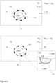
- Figs. 2 and 3 illustrate a method for manufacturing a coated interlaced substrate in a chemical deposition reactor.
- the interlaced substrate 10 to be coated comprises a first surface 10A and a second surface 10B. Coating process is implemented in an exemplary chemical deposition reactor comprising a reaction chamber 101 with a reaction space (deposition space) established by an interior of said reaction chamber 101.
- the reactor is configured to exploit principles of vapor-deposition based techniques, such as Atomic Layer Deposition (ALD).
- ALD Atomic Layer Deposition
- ALD is a chemical deposition method based on sequential introduction of at least two reactive precursor species to at least one substrate. It is to be understood, however, that one of these reactive precursors can be substituted by energy when using, for example, photon-enhanced ALD or plasma-assisted ALD, for example PEALD, leading to single precursor ALD processes.
- deposition of a pure element, such as metal requires only one precursor.
- Binary compounds, such as oxides can be created with one precursor chemical when the precursor chemical contains both of the elements of the binary material to be deposited.
- Thin films grown by ALD are dense, pinhole free and have uniform thickness.
- Chemical Vapour Deposition may be utilized.
- the at least one substrate is typically exposed to temporally separated precursor pulses in a reaction vessel to deposit material on the substrate surfaces by sequential self-saturating surface reactions.
- ALD comprises all applicable ALD based techniques and any equivalent or closely related technologies, such as, for example the following ALD sub-types: MLD (Molecular Layer Deposition), plasma-assisted ALD, PEALD (Plasma Enhanced Atomic Layer Deposition) and photon-enhanced Atomic Layer Deposition (known also as photo-ALD or flash enhanced ALD).
- a basic ALD deposition cycle resulting in deposition of a deposition layer (atomic layer), consists of four sequential steps: pulse A, purge A, pulse B and purge B.
- Pulse A consists of a first precursor fluid and pulse B of another precursor fluid.
- Inactive gas and a vacuum pump are typically used for purging gaseous reaction by-products and the residual reactant molecules from the reaction space during purge A and purge B.
- a deposition sequence comprises at least one deposition cycle. Deposition cycles are repeated until the deposition sequence has produced a thin film or coating of desired thickness. Deposition cycles can also be either simpler or more complex. For example, the cycles can include three or more reactant vapor pulses separated by purging steps, or certain purge steps can be omitted.
- photo-enhanced ALD has a variety of options, such as only one active precursor, with various options for purging. All these deposition cycles form a timed deposition sequence that is controlled by a logic unit or a microprocessor.
- the deposition reactor may be based on an ALD installation described in the U.S. patent no. 8211235 (Lindfors ), for example, or on the installation trademarked as Picosun R-200 Advanced ALD system available from Picosun Oy, Finland. Nevertheless, the features underlying a concept of the present invention can be incorporated into any other chemical deposition reactor embodied as an ALD, MLD or CVD device, for example, or any subtype thereof.
- the reaction chamber can be configured as an open-top vessel sealed with a lid (not shown).
- a lid (not shown).
- Such type of a reactor has an essentially circular layout when viewed from the top.
- the reaction chamber can be configured as a vessel loadable from side or from the bottom (not shown).
- the lid is configured as a hatch disposed laterally (within a sidewall) or at the bottom of the reactor vessel.
- Such type of reaction chambers may have a crossflow blown from the side, for example.
- the reactor further comprises a number of appliances configured to mediate a flow of fluids into the reaction space 101 (the reaction chamber). Mentioned appliances are provided as a number of intake lines (hereafter, feedlines) and associated switching and/or regulating valves (not shown).
- intake lines hereafter, feedlines
- switching and/or regulating valves not shown
- the reactor further comprises an evacuation line (not shown) for discharging an exhaust flow, such as excess carrier, precursor and reaction products, out of the reaction chamber.
- the evacuation line constitutes a fore-line for an evacuation pump unit and it may comprise, in some configurations, a closing valve, preferably upstream the pump unit. It is preferred that withdrawal of fluidic substance from the reaction chamber is implemented in an uninterrupted manner, whereby the pump unit, preferably configured as a vacuum pump, removes fluidic substance from the reaction chamber continuously during the entire deposition process.
- the interlaced substrate 10 is mounted onto a substrate holder 100, such that its first surface 10A faces the reaction space 101 and its second surface 10B is placed against the substrate holder 100.
- the interlaced substrate 10 can be provided in the form of a mesh or a web, such as a wire mesh, for example, optionally an expandable wire mesh.
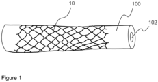
- the interlaced substrate 10 can be configured as an essentially tubular, pipe-like structure (see Fig. 1 ). Alternatively, the interlaced substrate 10 can be configured as an essentially flat, planar structure (not shown).
- the interlaced substrate 10 is an implantable medical device, such as a stent or a catheter.
- An exemplary configuration includes an expandable, mesh-wire type vascular stent.
- the substrate 10 forms at least a part of said medical device.
- the substrate holder 100 can be disposed essentially between the reaction chamber and any feedline (or a related appliance for directing precursor fluids into the reaction space). In some instances, the substrate holder 100 is received, at least partly, into the reaction chamber. For example, the substrate holder can be placed between the feedline and the reaction chamber such, that only a portion of said substrate holder (with the substrate 10 mounted thereto) is received into the reaction space, unless partial coating (e.g. lengthwise) of the substrate item is desired.
- the substrate holder 100 can be further positioned, at least partly, inside a feedline or form, at least partly, a part of the feedline.
- the substrate holder 100 is preferably made of an essentially fluid-permeable material, such as porous material, that enables unhindered fluid flow therethrough.
- the substrate holder can thus form a fluid-permeable passageway for precursor fluids entering the reaction space.
- the substrate holder 100 is positioned such that fluids, flowing via the feedline(s) into the reaction space 101, can enter said reaction space only by penetrating through the fluid-permeable material forming said holder of made of.
- the substrate holder 100 is an essentially tubular structure, onto which the interlaced substrate item 10 can be mounted.
- the substrate holder 100 can be provided as an essentially solid (without internal apertures and/or channels) piece made of fluid-permeable material.
- it is preferred that the holder 100 has an essentially hollow interior 102, in the form of a through-channel or a blind-end channel, for example.
- the substrate holder 100 includes all kinds of essentially tubular, channel-like shapes that enable uniform flow across their entire surfaces to attain the effect described herein below.
- the fluid-permeable material that constitutes the substrate holder 100 can be represented by any one of the porous metal, porous ceramics or porous polymer, including silicone polymer. Other materials, such as porous composites and semiconductor materials (e.g. silicon) are not excluded.
- the substrate holder 100 can be further configured as a fork- or rake-like arrangement with a common base portion and a number of protrusions / protruding "fingers" onto which the substrate items 10 to be coated can be mounted (not shown).
- the base portion of such holder can be made hollow and connected to a feedline or feedlines.
- the substrate holder for essentially flat, planar substrate items 10 can be implemented based on a similar principle.
- a number of substrate holders can be placed into the reaction space 101.
- position of the substrate holder 100 with regard to the reaction chamber is such, that fluids directed into the reactive space 101 via the feedlines, for example, enter the reaction space 101 via the fluid-permeable material.
- Precursor fluid(s) is/are delivered inside the reaction space 101 by means of at least one feedline connectable to a container with a precursor chemical.
- the reactor can comprise two, three or more feedlines and a corresponding number of inlets.
- the reactor can comprise as many feedlines and associated inlets as considered feasible in terms of the deposition process and the apparatus design.
- One or more such feedlines can be connected directly to the substrate holder 100, to feed fluids there into.
- the substrate holder 100 can be placed inside the reaction chamber and connected to the feedline(s) via its base portion.
- Precursor chemicals are delivered into the reaction space 101 (via feedlines) in a fluidic form.
- Precursor fluid delivered into the reaction space 101 is a gaseous substance comprising a predetermined precursor chemical A, B, B1, B2 ( Figs. 2 , 3 ) carried by an inert carrier. Whether the precursor is inherently provided in a gaseous form (e.g. NH 3 , or O 2 ), dilution of such precursor with a carrier fluid may not be required.
- Carrier fluid without the precursor chemical is indicated on Figs. 2 and 3 by a character X.
- Precursor chemicals are supplied into the reaction space from a supply source or sources configured as containers, cartridges or a piping system, for example (not shown).
- a supply source preferably contains a predetermined precursor species A, B, B1, B2 provided as a chemical compound, a molecule, or an element.
- Each source is equipped with at least one valve, provided as a manual closing valve, for example.
- a variety of precursor chemicals required for deposition reaction(s), such as ALD reaction(s) can be directed into the reaction space via a single feedline.
- precursor(s) can be provided in a gaseous form, such as ammonia gas (NH 3 ) or oxygen gas (O 2 ), which may be modified at least partly to ozone (O 3 ) by an appropriate equipment, such as ozone generator (not shown). Additionally or alternatively, precursor(s) can be provided in liquid or solid forms and vaporized prior to being admixed to the inert carrier.
- a gaseous form such as ammonia gas (NH 3 ) or oxygen gas (O 2 )
- O 3 oxygen gas
- precursor(s) can be provided in liquid or solid forms and vaporized prior to being admixed to the inert carrier.
- Inert carrier X is a fluid, preferably gas, such as nitrogen (N 2 ), argon (Ar) or any other suitable gaseous medium that possesses essentially zero reactivity towards the precursors (reactants) and the reaction products.
- Inert carrier gas X is supplied from a separate source or sources (not shown).
- the method disclosed hereby involves a number of deposition cycles, whereupon a first coating 1 is formed on the first surface 10A of the substrate and a second coating 2 is formed on the second surface 10B of the substrate ( Fig. 3 ).
- a number of precursor species are delivered into the reaction space resulting in formation of a deposition layer (an atomic layer), whereas production of a coating 10A, 10B comprises depositing at least one, but typically more than one deposition layer onto the substrate.
- Each deposition cycle comprises delivering, with a flow of fluid, precursor chemicals into the reaction space 101 such, that delivery of at least one precursor chemical into the reaction space 101 occurs via the fluid-permeable material the substrate holder 100 is made of.
- the deposition cycle comprises delivering at least two predetermined precursor chemicals into the reaction space 101, whereby a deposition layer produced across the first surface 10A of the substrate 10 and/or across the second surface 10B of said substrate.
- Delivery of said at least two predetermined precursor chemicals is implemented such that the first precursor chemical enters into the reaction space 101 via the reaction chamber (and a corresponding feedline or feedlines, not shown), whereas the second precursor chemical is directed into said reaction space 101 via the fluid-permeable substrate holder 100.
- the deposition layers forming the first coating 1 differ from the deposition layers forming the second coating 2 by virtue of at least composition thereof, thus rendering the coated surfaces by distinct surface chemistry.
- Other differentiating factors include, but are not limited to thickness and density of the final coating films, ability to attract and repel water molecules, as well as any other chemical, physical- and/or biological property.
- Biological properties can include e.g. specific responses at a substrate - (biological) host interface, an ability of not having toxic or injurious effects on biological systems, an ability to act as a suitable implantable material, an antimicrobial activity, and the like.
- Fluidic flow through the essentially fluid-permeable material 100 can be controlled by pressure difference generated across said material with the evacuation pump and a number of regulating devices, such as switch valves equipped with mass-flow controller(s) and/or gas flow meter(s), for example.
- Other control means include conventional appliances, such as gas- and pressure sensors.
- the chemical deposition reactor advantageously comprises an (automated) control system, implemented as a computer unit, for example, and comprising at least one processor and a memory with an appropriate computer program or software.
- the coating(s) 1, 2 is/are deposited onto the interlaced substrate 10 with Atomic Layer Deposition (ALD).
- ALD Atomic Layer Deposition
- An interlaced substrate 10 is obtained in the form of a stent device provided in the form of an essentially tubular, scaffold mesh-type structure.
- the stent can be configured as an implantable device, such as a self-expandable metallic stent.
- the stent has an outer surface 10A and an inner surface 10B.
- the stent 10 is positioned onto / around the fluid-permeable substrate holder 100 such, that its first surface 10A faces the reaction space 101 and its second surface is placed against the substrate holder ( Fig. 1 ).
- the fluid-permeable substrate holder is made of a porous material that enables unrestricted flow of fluids, such as gaseous media, therethrough.
- the fluid-permeable substrate holder 100 can be configured as an essentially tubular inlet comprising the hollow interior 102.
- the substrate holder 100 with the stent 10 mounted thereon, as shown on Fig. 1 is placed into the reaction space 101 formed by a reaction chamber of an exemplary ALD reactor.
- a reaction chamber of an exemplary ALD reactor By the way of example, the installation R-200 Advanced ALD system available from Picosun Oy, Finland, can be utilized.
- the holder 100 is connected to a feedline or feedlines (the feedline is not shown). When fluid is directed into the reaction chamber via the feedline(s) connected to the holder 100, fluid enters the reaction space 101 essentially through the fluid-permeable material said holder is made of.
- the reactor further comprises at least one feedline through which fluid(s) are delivered into the reaction space.
- feedline(s) is/are not connected to the substrate holder 100.
- Fluid flow into the reaction space 101 through the feedline(s), onto which the substrate holder 100 is mounted or incorporated, and through the interior 102 of said substrate holder is further referred to as a flow from the "inside” (“in”), whereas fluid flow directly entering the reaction space (via feedline(s) provided with the reaction space 101, but not shown with regard to the holder 100) is referred to as a flow from the "outside” (“out”)).
- the flow from the interior side 102 of the tubular substrate holder 100 to the reaction space 101 through the essentially fluid-permeable material (100) can be controlled by adjusting pressure difference (P in /P out ) generated across the essentially fluid-permeable substrate walls.
- pressure difference P in /P out
- velocity of fluids flowing across the fluid-permeable wall in both in- and out-directions
- Fluidic flow through the essentially fluid-permeable material 100 can be controlled by pressure difference generated across said material an evacuation pump provided in chemical deposition reactor and regulating devices, as described herein above.
- the flow rate regarded as very low is equal to or less than 10 sccm, preferably, equal to or less than 1 sccm, still preferably, equal to or less than 0.1 sccm. Seem refers to standard cubic centimeters per minute; cm 3 /min in standard conditions for temperature and pressure of the fluid, wherein said standard temperature is 0 deg C (273 K) and standard pressure is 1 atm).
- Example 2 Deposition of the interlaced substrate 10 with a coating
- inert carrier fluid X such as nitrogen gas (N 2 )
- N 2 nitrogen gas
- precursor A such as titanium tetrachloride (TiCl 4 )
- SiCl 4 titanium tetrachloride
- Purge by directing inert fluid X into the reaction space via the reaction chamber and, optionally, via the feedline connected to the substrate holder 100. Purge duration 1 - 100 s, preferably, 10 s.
- a second precursor B such as ammonia gas (NH 3 ) into the reaction space via the feedline connected to the tubular substrate holder 100, while directing the inert carrier X (N 2 ) into the reaction chamber.
- precursor B is forced to penetrate through the fluid-permeable wall 100 and reside onto both surfaces 10A and 10B of the interlaced substrate 10.
- the precursor B enters chemical reaction with precursor A thus forming a deposition layer AB, hereby, titanium nitride (TiN), on both exterior- and interior surfaces 10A and 10B, respectively ( Fig. 2 , lower box).
- the coating can comprise at least one deposition layer AB or a "stack" of identical deposition layers AB.
- Example 3 Deposition of the exterior- and interior (10A, 10B) surfaces of the interlaced substrate 10 with coatings 1, 2 having distinct surface chemistry
- step 1a Same as step 1a in Example 2 ( Fig. 3 , upper box). Conformal deposition of the precursor A, hereby, TiCl 4 , for example, onto the entire substrate 10 (surfaces 10A, 10B).
- the procedure allows for producing a deposition layer AB1 (hereby, titanium oxide, TiO n ) on the exterior surface 10A along with producing a deposition layer AB2 (hereby, titanium nitride, TiN) on the interior surface 10B of the substrate ( Fig 3 , lower box).
- a deposition layer AB1 hereby, titanium oxide, TiO n
- a deposition layer AB2 hereby, titanium nitride, TiN
- the precursors B1 and B2 can be delivered into the reactions space simultaneously or one by one. In the latter case, delivery of the precursor fluid is accompanied by delivery of the carrier fluid X from the opposite side (not shown).
- delivery of precursor B1 into the reaction chamber is accompanied by guiding inert fluid X through the substrate holder 100; whereas delivery of B2 into the reaction space 101 through the substrate holder 100 is accompanied by guiding inert fluid X into the reaction chamber.
- any suitable precursor e.g. B3, not shown, which is known to react differently with B1 compared to B2, for selectively coating only one surface (10A or 10B) of the substrate.
- the outer surface 10A can be deposited with a 1 nm coating (1), whereas the inner surface - with a 0,5 nm coating (2), for example.
- Each coating 1, 2 thus comprises at least one deposition layer AB1, AB2.
- the entire substrate 10 can be deposited with an at least one deposition layer AB (e.g. TiN), in a manner shown on Fig. 2 (Example 2). Thereafter, the procedure according to the Example 3 ( Fig. 3 ) can be applied to establish at least one deposition layer AB1 (e.g. TiO 2 ) on the outer substrate surface 10A or on the inner surface 10B.
- AB e.g. TiN
- Deposition series " AB (conformal, surfaces 10A, 10B) + AB1 (surface 10A)” and/or " AB + AB2 (surface 10B)” and/or " AB + AB1 and AB2 " can be repeated n times as desired to produce heterogeneous coatings with uniform thickness across the substrate 10 or thickness varying for surfaces 10A and 10B.
- the coating 1 (surface 10A) can comprise deposition layers (AB) n and (AB1) n
- the coating 2 (surface 10B) can comprise deposition layers (AB) n and (AB2) n .
- coatings 1, 2 with distinct composition e.g. TiO 2 and TiN
- at least one common precursor such as TiC I4
- the procedure can be further implemented as follows.
- inert carrier fluid X such as nitrogen gas (N 2 )
- N 2 nitrogen gas
- a (common) precursor A e.g. TiCl 4
- step 4a Deliver precursor B (e.g. HN 3 ) into the reaction space 101 via the reaction chamber in similar manner as for step 3a.
- precursor B e.g. HN 3
- conformal growth of the deposition layer AB can be attained for the entire substrate.
- delivery of the precursor B into the reaction space can be optionally accompnied by re-establishing the inert counterflow (X) through the substrate holder 100.
- Inert counterflow can be established if growth of the deposition layer AB (TiN) is desired only for the outer surface 10A.
- Procedure allows for conducting deposition series " AB1 (surface 10A) + AB (conformal, surfaces 10A, 10B)" and/or " AB1 (surface 10A) + AB (only for the surface 10A)".
- AB1 surface 10A + AB (conformal, surfaces 10A, 10B)
- AB1 surface 10A + AB (only for the surface 10A)
- the deposition cycles 1-2 and 3-4 can be repeated n times.
- the substrate 10 is rendered with surfaces 10A, 10B with different properties, attainable, in this Example, by regulating the inert counterflow X from the interior 102 of the substrate holder 100.
- delivery of any one of the precursor chemicals into the reaction space 101 is accompanied by generating a counter flow of inert fluid in a direction essentially opposite to the direction of delivery of precursor chemicals into the reaction space 101.
- the method further allows for selective deposition of coatings on one of the surfaces 10A or 10B, while deposition on the other surface can be sustained or prevented.
- a hydrophobic precursor such as tridecafluoro-1,1,2,2-tetrahydrooctylmethyl-bis(dimethylamino)silane (also known as FOMB(DMA)S or C 8 F 13 H 4 (CH 3 )Si(N(CH 3 ) 2 ) 2 ), can be used as precursor A to be deposited conformally on all surfaces of the substrate 10, in a manner described hereinabove.
- FOMB(DMA)S tridecafluoro-1,1,2,2-tetrahydrooctylmethyl-bis(dimethylamino)silane
- any suitable precursor B can be delivered into the reaction space 101 via the reaction chamber, while maintaining pressure difference across the interior and exterior surfaces of the fluid-permeable substrate holder 100 such, that said second precursor B does not penetrate inside the substrate holder (hereby, P in > P out ) and reacts with precursor A only at the outer surface 10A.
- Region-specific coating can be attained by establishing the inert counterflow through the substrate holder 100 in a manner described hereinabove. Deposition cycles can be repeated n times until the coating (1, 2) with desired thickness is obtained. As a consequence, only the inner surface 10B of the tubular substrate 10, such as stent, shall be deposited with the hydrophobic film.
- the precursor chemicals e.g. A, B, B1, B2
- the reaction space 101 is purged with inert fluid X after each precursor pulse.
- Inert fluid X can be guided into the reaction chamber via any feedline or feedlines including the feedline(s) connected to the substrate holder 100.
- purging of the fluid-permeable material occurs in direction from the interior 102 of the substrate holder towards the reaction space 101.
- Purging the substrate holder 100 generally requires more time than purging the reaction space 101, due to slower penetration of fluids through the fluid-permeable material.
- purging can be a process, in where reverse flow of inert fluid (e.g. N 2 ) is established, thereupon fluid from the reaction space is sucked into the tube-shaped substrate holder through the porous walls.
- inert fluid e.g. N 2
- Reverse flow can be regulated by a valve provided on an appropriate feedline (not shown).
- the precursors described hereinabove to deposit the coatings 1, 2 are mere examples of compounds, which can be established, by ALD methods, from a metal-containing precursor (TiCl 4 ) and secondary chemicals, such as gases (NH 3 , O 3 /H 2 O). Nevertheless, any compound suitable for establishing a chemical reaction by ALD or CVD methods can be utilized within the concept of the present invention.
- the coatings 1, 2 can be established from a metal-containing precursor (A) and at least two non-similar gaseous substances (B1, B2). In some other instances, the coatings 1, 2 can be established from a number of metal-containing precursors. Utilization of various compounds (oxides, nitrides sulfides, etc.) that comprise elements other than metal, such as silicon dioxide, SiO 2 , for example, is also not excluded.
- Non-limiting examples for the coatings 1, 2 include aluminium oxide (Al 2 O 3 ), zinc oxide (ZnO), or a combination thereof. These materials are biocompatible and dissolve in controllable manner when in contact with bodily fluids, thus enabling production of implantable devices for controlled drug release.
- a coated item 10 configured as an interlaced structure can be produced by the method according to the embodiments.
- the item comprises a first coating 1 on a first surface 10A and a second coating 2 on a second surface 10B, wherein the first coating 1 and the second coating 2 differ from one another by virtue of at least composition thereof.
- the coated item can be configured as an implantable device, such as a stent, e.g. a vascular stent, or a catheter.
- An implantable medical device 10 is further described configured as an interlaced structure that comprises a first coating 1 on a first surface 10A and a second coating 2 on a second surface 10B, wherein the first coating 1 and the second coating 2 differ from one another by virtue of at least composition thereof.
- the coated implantable medical device 10 is a stent or a catheter.
Landscapes
- Chemical & Material Sciences (AREA)
- Engineering & Computer Science (AREA)
- Organic Chemistry (AREA)
- Mechanical Engineering (AREA)
- Metallurgy (AREA)
- Materials Engineering (AREA)
- Chemical Kinetics & Catalysis (AREA)
- General Chemical & Material Sciences (AREA)
- Health & Medical Sciences (AREA)
- Inorganic Chemistry (AREA)
- Life Sciences & Earth Sciences (AREA)
- Veterinary Medicine (AREA)
- Public Health (AREA)
- Animal Behavior & Ethology (AREA)
- General Health & Medical Sciences (AREA)
- Biomedical Technology (AREA)
- Heart & Thoracic Surgery (AREA)
- Epidemiology (AREA)
- Vascular Medicine (AREA)
- Transplantation (AREA)
- Oral & Maxillofacial Surgery (AREA)
- Cardiology (AREA)
- Biophysics (AREA)
- Pulmonology (AREA)
- Anesthesiology (AREA)
- Hematology (AREA)
- Surgery (AREA)
- Chemical Vapour Deposition (AREA)
- Extrusion Moulding Of Plastics Or The Like (AREA)
Claims (14)
- Procédé de fabrication d'un substrat entrelacé revêtu dans un réacteur de dépôt chimique, comprenant :l'obtention d'un réacteur de dépôt chimique avec un espace de réacteur (101) formé par une chambre de réaction et configuré pour recevoir, au moins en partie, un support de substrat (100) constitué d'un matériau perméable aux fluides, sur lequel un substrat entrelacé (10) est monté de telle manière qu'une première surface (10A) du substrat fait face à l'espace de réaction (101) et une seconde surface (10B) du substrat est placée contre le support de substrat (100) etdans un certain nombre de cycles de dépôt, formant un premier revêtement (1) sur la première surface (10A) et/ou formant un second revêtement (2) sur la seconde surface (10B),chaque cycle de dépôt comprenant la délivrance, avec un écoulement de fluide, d'un précurseur chimique dans l'espace de réaction (101) de telle manière que la délivrance de l'au moins un précurseur chimique dans l'espace de réaction (101) se produit via ledit matériau perméable aux fluides.
- Procédé selon la revendication 1, dans lequel le support de substrat (100) a un intérieur essentiellement creux (102), dans lequel ledit au moins un précurseur chimique est reçu.
- Procédé selon l'une quelconque des revendications 1 ou 2, dans lequel le cycle de dépôt comprend au moins deux précurseurs chimiques prédéterminés dans l'espace de réaction (101), moyennant quoi une couche de dépôt (AB, AB1, AB2) est produite à travers la première surface (10A) du substrat (10) et/ou à travers la seconde surface (10B) dudit substrat.
- Procédé selon l'une quelconque ds revendications précédentes, dans lequel un premier précurseur chimique prédéterminé est délivré dans l'espace de réaction (101) via la chambre de réaction et un second précurseur chimique prédéterminé est délivré dans l'espace de réaction (101) via le support de substrat perméable aux fluides (100).
- Procédé selon l'une quelconque des revendications précédentes, dans lequel les précurseurs chimiques sont délivrés dans l'espace de réaction (101) en impulsions séquentielles, temporellement séparées, éventuellement alternées en purgeant l'espace de réaction (101) avec un fluide inerte.
- Procédé selon l'une quelconque des revendications précédentes, dans lequel la délivrance de l'un quelconque des précurseurs chimiques dans l'espace de réaction (101) est accompagnée par la production d'un contre écoulement de fluide inerte dans une direction essentiellement opposée à la direction de délivrance de précurseurs chimiques dans l'espace de réaction (101) .
- Procédé selon l'une quelconque des revendications précédentes, dans lequel l'un quelconque du premier revêtement (1) et du second revêtement (2) sont formés par l'au moins une couche de dépôt (AB, AB1, AB2) déposées à travers la première surface (10A) du substrat (10) et/ou à travers la second surface (10B) dudit substrat.
- Procédé selon l'une quelconque des revendications précédentes, dans lequel les couches de dépôt formant le premier revêtement (1) diffèrent des couches de dépôt formant le second revêtement (2) en vertu d'au moins leur composition.
- Procédé selon l'une quelconque des revendications précédentes, dans lequel la formation sélective du revêtement (1, 2) sur la première surface et/ou sur la seconde surface est régulée par l'ajustement de la pression du fluide s'écoulant dans l'espace de réaction (101) via la chambre de réaction et/ou via le support de substrat perméable aux fluides (100).
- Procédé selon l'une quelconque des revendications précédentes, dans lequel le support de substrat (100) est constitué d'un matériau perméable aux fluides choisi dans le groupe constitué par un métal poreux, une céramique poreuse et un polymère poreux.
- Procédé selon l'une quelconque des revendications précédentes, dans lequel le support de substrat (100) est une structure essentiellement tubulaire.
- Procédé selon l'une quelconque des revendications précédentes, dans lequel le substrat entrelacé (10) est une structure essentiellement tubulaire formée par une maille ou une toile.
- Procédé selon l'une quelconque des revendications précédentes, dans lequel le substrat entrelacé (10) est un dispositif médical implantable, tel qu'un stent ou un cathéter, ou forme une partie de ce dispositif.
- Procédé selon l'une quelconque des revendications précédentes, dans lequel le revêtement (1, 2) est déposé sur le substrat entrelacé (10) avec un dépôt de coche atomique (ALD).
Applications Claiming Priority (1)
| Application Number | Priority Date | Filing Date | Title |
|---|---|---|---|
| US201962858069P | 2019-06-06 | 2019-06-06 |
Publications (2)
| Publication Number | Publication Date |
|---|---|
| EP3747480A1 EP3747480A1 (fr) | 2020-12-09 |
| EP3747480B1 true EP3747480B1 (fr) | 2023-03-29 |
Family
ID=71016357
Family Applications (1)
| Application Number | Title | Priority Date | Filing Date |
|---|---|---|---|
| EP20178402.2A Active EP3747480B1 (fr) | 2019-06-06 | 2020-06-05 | Fabrication d'articles revêtus |
Country Status (5)
| Country | Link |
|---|---|
| US (2) | US11668005B2 (fr) |
| EP (1) | EP3747480B1 (fr) |
| JP (1) | JP2021001396A (fr) |
| CN (1) | CN112048709B (fr) |
| FI (1) | FI3747480T3 (fr) |
Citations (3)
| Publication number | Priority date | Publication date | Assignee | Title |
|---|---|---|---|---|
| WO2000062830A2 (fr) * | 1999-04-19 | 2000-10-26 | Boston Scientific Limited | Enrobage de dispositifs medicaux par suspension dans un courant d'air |
| US7588642B1 (en) * | 2004-11-29 | 2009-09-15 | Advanced Cardiovascular Systems, Inc. | Abluminal stent coating apparatus and method using a brush assembly |
| US20180110637A1 (en) * | 2015-06-26 | 2018-04-26 | Nsvascular, Inc. | Thin-film micromesh covers for medical devices and related methods |
Family Cites Families (24)
| Publication number | Priority date | Publication date | Assignee | Title |
|---|---|---|---|---|
| US7049210B2 (en) * | 2002-09-23 | 2006-05-23 | Applied Materials, Inc. | Method of implanting a substrate and an ion implanter for performing the method |
| US20040142558A1 (en) * | 2002-12-05 | 2004-07-22 | Granneman Ernst H. A. | Apparatus and method for atomic layer deposition on substrates |
| US7285483B2 (en) * | 2003-06-26 | 2007-10-23 | Silitronic Ag | Coated semiconductor wafer, and process and apparatus for producing the semiconductor wafer |
| JP4965253B2 (ja) * | 2003-08-08 | 2012-07-04 | インテグリス・インコーポレーテッド | 回転可能ベース上に鋳造されるモノリシック多孔性パッドを作製する方法および材料 |
| US8211235B2 (en) | 2005-03-04 | 2012-07-03 | Picosun Oy | Apparatuses and methods for deposition of material on surfaces |
| US20080299337A1 (en) | 2006-02-09 | 2008-12-04 | Isoflux, Inc. | Method for the formation of surfaces on the inside of medical devices |
| US7381966B2 (en) * | 2006-04-13 | 2008-06-03 | Integrated Micro Sensors, Inc. | Single-chip monolithic dual-band visible- or solar-blind photodetector |
| WO2008118788A1 (fr) * | 2007-03-23 | 2008-10-02 | Illinois Tool Works Inc. | Stratifié décoratif entrelacé tridimensionnel amélioré et son procédé de fabrication |
| SG151139A1 (en) * | 2007-10-01 | 2009-04-30 | Creative Tech Ltd | A method and apparatus for reverse printing on a flexible lenticular substrate |
| JP2010213984A (ja) * | 2009-03-18 | 2010-09-30 | Naisemu:Kk | 柔軟剤及び/又は保湿剤含有生体埋込用医療材料、該医療材料中の柔軟剤及び/又は保湿剤の含有量を調整する方法及び、該生体内埋込用医療材料の製造方法 |
| KR101060607B1 (ko) | 2009-07-09 | 2011-08-31 | 전남대학교산학협력단 | 티탄산화물 박막코팅을 이용한 약물방출 스텐트의 제조방법 |
| US8567340B2 (en) * | 2009-08-12 | 2013-10-29 | Abbott Cardiovascular Systems Inc. | System and method for coating a medical device |
| US20130022658A1 (en) * | 2011-07-23 | 2013-01-24 | Synos Technology, Inc. | Depositing material with antimicrobial properties on permeable substrate using atomic layer deposition |
| WO2013142344A1 (fr) | 2012-03-20 | 2013-09-26 | North Carolina State University | Procédés et appareil pour le dépôt de couche atomique à la pression atmosphérique |
| US9404182B2 (en) * | 2012-10-22 | 2016-08-02 | Sensor Electronic Technology, Inc. | Multi-wafer reactor |
| FR3014115B1 (fr) * | 2013-12-02 | 2017-04-28 | Office National Detudes Et De Rech Aerospatiales Onera | Procede et systeme de depot d'oxyde sur un composant poreux |
| CN103924202A (zh) * | 2014-04-03 | 2014-07-16 | 西南交通大学 | 一种金属支架表面改性方法 |
| US9567685B2 (en) * | 2015-01-22 | 2017-02-14 | Lam Research Corporation | Apparatus and method for dynamic control of plated uniformity with the use of remote electric current |
| US20170037509A1 (en) * | 2015-07-13 | 2017-02-09 | Tokyo Electron Limited | Method for coating or filling a porous material |
| JP6747220B2 (ja) * | 2016-09-28 | 2020-08-26 | 東京エレクトロン株式会社 | 基板処理装置及び基板処理方法 |
| WO2018189413A1 (fr) * | 2017-04-10 | 2018-10-18 | Picosun Oy | Dépôt uniforme |
| US11201288B2 (en) * | 2017-05-26 | 2021-12-14 | Universal Display Corporation | Generalized organic vapor jet depositor capable of high resolution printing and method for OVJP printing |
| KR102218855B1 (ko) * | 2017-07-12 | 2021-02-23 | 주식회사 엘지화학 | 다공성 기재의 표면 코팅 장치 및 방법 |
| WO2020245492A1 (fr) * | 2019-06-06 | 2020-12-10 | Picosun Oy | Entrée poreuse |
-
2020
- 2020-06-05 US US16/894,049 patent/US11668005B2/en active Active
- 2020-06-05 CN CN202010506252.7A patent/CN112048709B/zh active Active
- 2020-06-05 JP JP2020098387A patent/JP2021001396A/ja active Pending
- 2020-06-05 EP EP20178402.2A patent/EP3747480B1/fr active Active
- 2020-06-05 FI FIEP20178402.2T patent/FI3747480T3/fi active
-
2023
- 2023-04-25 US US18/306,340 patent/US20230257870A1/en active Pending
Patent Citations (3)
| Publication number | Priority date | Publication date | Assignee | Title |
|---|---|---|---|---|
| WO2000062830A2 (fr) * | 1999-04-19 | 2000-10-26 | Boston Scientific Limited | Enrobage de dispositifs medicaux par suspension dans un courant d'air |
| US7588642B1 (en) * | 2004-11-29 | 2009-09-15 | Advanced Cardiovascular Systems, Inc. | Abluminal stent coating apparatus and method using a brush assembly |
| US20180110637A1 (en) * | 2015-06-26 | 2018-04-26 | Nsvascular, Inc. | Thin-film micromesh covers for medical devices and related methods |
Also Published As
| Publication number | Publication date |
|---|---|
| CN112048709A (zh) | 2020-12-08 |
| FI3747480T3 (fi) | 2023-05-24 |
| US20230257870A1 (en) | 2023-08-17 |
| US11668005B2 (en) | 2023-06-06 |
| JP2021001396A (ja) | 2021-01-07 |
| EP3747480A1 (fr) | 2020-12-09 |
| US20200385857A1 (en) | 2020-12-10 |
| CN112048709B (zh) | 2024-03-08 |
Similar Documents
| Publication | Publication Date | Title |
|---|---|---|
| US12416081B2 (en) | Manifolds for uniform vapor deposition | |
| US7498057B2 (en) | Deposition methods | |
| US11830731B2 (en) | Semiconductor deposition reactor manifolds | |
| US9873942B2 (en) | Methods of vapor deposition with multiple vapor sources | |
| US7396565B2 (en) | Multiple precursor cyclical deposition system | |
| KR20070039958A (ko) | 고 생산성 화학 기상 증착 장치 및 방법 | |
| US20100048032A1 (en) | Process gas delivery for semiconductor process chamber | |
| JP2011171752A (ja) | 短時促進原子層堆積 | |
| JP2000212752A (ja) | 反応チャンバガス流入方法及びそれに用いるシャワ―ヘッド | |
| US10253414B2 (en) | Liquid phase atomic layer deposition | |
| KR20150031222A (ko) | 산소 결핍 금속 필름을 증착시키는 방법 | |
| EP1664374B1 (fr) | Formation de couches contenant du dioxyde de silicium par des procedes d'epitaxie en couches atomiques | |
| US12065730B2 (en) | Coating of fluid-permeable materials | |
| EP3747480B1 (fr) | Fabrication d'articles revêtus | |
| TW202146701A (zh) | 氣相沉積系統、在基材上形成氮化釩層之方法、直接液體注入系統 | |
| FI129344B (en) | Coating of particulate matter | |
| JP2021066959A (ja) | 膜堆積プロセスにおける通常のパルスプロファイルの修正 | |
| JP2008208404A (ja) | 薄膜、及びその薄膜製造方法 |
Legal Events
| Date | Code | Title | Description |
|---|---|---|---|
| PUAI | Public reference made under article 153(3) epc to a published international application that has entered the european phase |
Free format text: ORIGINAL CODE: 0009012 |
|
| STAA | Information on the status of an ep patent application or granted ep patent |
Free format text: STATUS: THE APPLICATION HAS BEEN PUBLISHED |
|
| AK | Designated contracting states |
Kind code of ref document: A1 Designated state(s): AL AT BE BG CH CY CZ DE DK EE ES FI FR GB GR HR HU IE IS IT LI LT LU LV MC MK MT NL NO PL PT RO RS SE SI SK SM TR |
|
| AX | Request for extension of the european patent |
Extension state: BA ME |
|
| STAA | Information on the status of an ep patent application or granted ep patent |
Free format text: STATUS: REQUEST FOR EXAMINATION WAS MADE |
|
| 17P | Request for examination filed |
Effective date: 20210609 |
|
| RBV | Designated contracting states (corrected) |
Designated state(s): AL AT BE BG CH CY CZ DE DK EE ES FI FR GB GR HR HU IE IS IT LI LT LU LV MC MK MT NL NO PL PT RO RS SE SI SK SM TR |
|
| REG | Reference to a national code |
Ref country code: DE Ref legal event code: R079 Ref document number: 602020009150 Country of ref document: DE Free format text: PREVIOUS MAIN CLASS: A61L0031080000 Ipc: C23C0016040000 |
|
| GRAP | Despatch of communication of intention to grant a patent |
Free format text: ORIGINAL CODE: EPIDOSNIGR1 |
|
| STAA | Information on the status of an ep patent application or granted ep patent |
Free format text: STATUS: GRANT OF PATENT IS INTENDED |
|
| RIC1 | Information provided on ipc code assigned before grant |
Ipc: A61L 31/08 20060101ALI20220930BHEP Ipc: A61L 29/10 20060101ALI20220930BHEP Ipc: C23C 16/458 20060101ALI20220930BHEP Ipc: C23C 16/455 20060101ALI20220930BHEP Ipc: C23C 16/34 20060101ALI20220930BHEP Ipc: C23C 16/40 20060101ALI20220930BHEP Ipc: C23C 16/04 20060101AFI20220930BHEP |
|
| INTG | Intention to grant announced |
Effective date: 20221019 |
|
| GRAS | Grant fee paid |
Free format text: ORIGINAL CODE: EPIDOSNIGR3 |
|
| GRAA | (expected) grant |
Free format text: ORIGINAL CODE: 0009210 |
|
| STAA | Information on the status of an ep patent application or granted ep patent |
Free format text: STATUS: THE PATENT HAS BEEN GRANTED |
|
| AK | Designated contracting states |
Kind code of ref document: B1 Designated state(s): AL AT BE BG CH CY CZ DE DK EE ES FI FR GB GR HR HU IE IS IT LI LT LU LV MC MK MT NL NO PL PT RO RS SE SI SK SM TR |
|
| REG | Reference to a national code |
Ref country code: CH Ref legal event code: EP |
|
| REG | Reference to a national code |
Ref country code: DE Ref legal event code: R096 Ref document number: 602020009150 Country of ref document: DE |
|
| REG | Reference to a national code |
Ref country code: AT Ref legal event code: REF Ref document number: 1556709 Country of ref document: AT Kind code of ref document: T Effective date: 20230415 |
|
| REG | Reference to a national code |
Ref country code: IE Ref legal event code: FG4D |
|
| REG | Reference to a national code |
Ref country code: NL Ref legal event code: FP |
|
| REG | Reference to a national code |
Ref country code: LT Ref legal event code: MG9D |
|
| PG25 | Lapsed in a contracting state [announced via postgrant information from national office to epo] |
Ref country code: RS Free format text: LAPSE BECAUSE OF FAILURE TO SUBMIT A TRANSLATION OF THE DESCRIPTION OR TO PAY THE FEE WITHIN THE PRESCRIBED TIME-LIMIT Effective date: 20230329 Ref country code: NO Free format text: LAPSE BECAUSE OF FAILURE TO SUBMIT A TRANSLATION OF THE DESCRIPTION OR TO PAY THE FEE WITHIN THE PRESCRIBED TIME-LIMIT Effective date: 20230629 Ref country code: LV Free format text: LAPSE BECAUSE OF FAILURE TO SUBMIT A TRANSLATION OF THE DESCRIPTION OR TO PAY THE FEE WITHIN THE PRESCRIBED TIME-LIMIT Effective date: 20230329 Ref country code: LT Free format text: LAPSE BECAUSE OF FAILURE TO SUBMIT A TRANSLATION OF THE DESCRIPTION OR TO PAY THE FEE WITHIN THE PRESCRIBED TIME-LIMIT Effective date: 20230329 Ref country code: HR Free format text: LAPSE BECAUSE OF FAILURE TO SUBMIT A TRANSLATION OF THE DESCRIPTION OR TO PAY THE FEE WITHIN THE PRESCRIBED TIME-LIMIT Effective date: 20230329 |
|
| PGFP | Annual fee paid to national office [announced via postgrant information from national office to epo] |
Ref country code: NL Payment date: 20230620 Year of fee payment: 4 Ref country code: FR Payment date: 20230628 Year of fee payment: 4 Ref country code: DE Payment date: 20230620 Year of fee payment: 4 |
|
| REG | Reference to a national code |
Ref country code: AT Ref legal event code: MK05 Ref document number: 1556709 Country of ref document: AT Kind code of ref document: T Effective date: 20230329 |
|
| PG25 | Lapsed in a contracting state [announced via postgrant information from national office to epo] |
Ref country code: SE Free format text: LAPSE BECAUSE OF FAILURE TO SUBMIT A TRANSLATION OF THE DESCRIPTION OR TO PAY THE FEE WITHIN THE PRESCRIBED TIME-LIMIT Effective date: 20230329 Ref country code: GR Free format text: LAPSE BECAUSE OF FAILURE TO SUBMIT A TRANSLATION OF THE DESCRIPTION OR TO PAY THE FEE WITHIN THE PRESCRIBED TIME-LIMIT Effective date: 20230630 |
|
| PG25 | Lapsed in a contracting state [announced via postgrant information from national office to epo] |
Ref country code: SM Free format text: LAPSE BECAUSE OF FAILURE TO SUBMIT A TRANSLATION OF THE DESCRIPTION OR TO PAY THE FEE WITHIN THE PRESCRIBED TIME-LIMIT Effective date: 20230329 Ref country code: RO Free format text: LAPSE BECAUSE OF FAILURE TO SUBMIT A TRANSLATION OF THE DESCRIPTION OR TO PAY THE FEE WITHIN THE PRESCRIBED TIME-LIMIT Effective date: 20230329 Ref country code: PT Free format text: LAPSE BECAUSE OF FAILURE TO SUBMIT A TRANSLATION OF THE DESCRIPTION OR TO PAY THE FEE WITHIN THE PRESCRIBED TIME-LIMIT Effective date: 20230731 Ref country code: ES Free format text: LAPSE BECAUSE OF FAILURE TO SUBMIT A TRANSLATION OF THE DESCRIPTION OR TO PAY THE FEE WITHIN THE PRESCRIBED TIME-LIMIT Effective date: 20230329 Ref country code: EE Free format text: LAPSE BECAUSE OF FAILURE TO SUBMIT A TRANSLATION OF THE DESCRIPTION OR TO PAY THE FEE WITHIN THE PRESCRIBED TIME-LIMIT Effective date: 20230329 Ref country code: AT Free format text: LAPSE BECAUSE OF FAILURE TO SUBMIT A TRANSLATION OF THE DESCRIPTION OR TO PAY THE FEE WITHIN THE PRESCRIBED TIME-LIMIT Effective date: 20230329 |
|
| PGFP | Annual fee paid to national office [announced via postgrant information from national office to epo] |
Ref country code: IT Payment date: 20230630 Year of fee payment: 4 Ref country code: CH Payment date: 20230702 Year of fee payment: 4 |
|
| PG25 | Lapsed in a contracting state [announced via postgrant information from national office to epo] |
Ref country code: SK Free format text: LAPSE BECAUSE OF FAILURE TO SUBMIT A TRANSLATION OF THE DESCRIPTION OR TO PAY THE FEE WITHIN THE PRESCRIBED TIME-LIMIT Effective date: 20230329 Ref country code: PL Free format text: LAPSE BECAUSE OF FAILURE TO SUBMIT A TRANSLATION OF THE DESCRIPTION OR TO PAY THE FEE WITHIN THE PRESCRIBED TIME-LIMIT Effective date: 20230329 Ref country code: IS Free format text: LAPSE BECAUSE OF FAILURE TO SUBMIT A TRANSLATION OF THE DESCRIPTION OR TO PAY THE FEE WITHIN THE PRESCRIBED TIME-LIMIT Effective date: 20230729 |
|
| REG | Reference to a national code |
Ref country code: DE Ref legal event code: R097 Ref document number: 602020009150 Country of ref document: DE |
|
| PG25 | Lapsed in a contracting state [announced via postgrant information from national office to epo] |
Ref country code: MC Free format text: LAPSE BECAUSE OF FAILURE TO SUBMIT A TRANSLATION OF THE DESCRIPTION OR TO PAY THE FEE WITHIN THE PRESCRIBED TIME-LIMIT Effective date: 20230329 |
|
| PG25 | Lapsed in a contracting state [announced via postgrant information from national office to epo] |
Ref country code: MC Free format text: LAPSE BECAUSE OF FAILURE TO SUBMIT A TRANSLATION OF THE DESCRIPTION OR TO PAY THE FEE WITHIN THE PRESCRIBED TIME-LIMIT Effective date: 20230329 Ref country code: DK Free format text: LAPSE BECAUSE OF FAILURE TO SUBMIT A TRANSLATION OF THE DESCRIPTION OR TO PAY THE FEE WITHIN THE PRESCRIBED TIME-LIMIT Effective date: 20230329 Ref country code: CZ Free format text: LAPSE BECAUSE OF FAILURE TO SUBMIT A TRANSLATION OF THE DESCRIPTION OR TO PAY THE FEE WITHIN THE PRESCRIBED TIME-LIMIT Effective date: 20230329 |
|
| PLBE | No opposition filed within time limit |
Free format text: ORIGINAL CODE: 0009261 |
|
| STAA | Information on the status of an ep patent application or granted ep patent |
Free format text: STATUS: NO OPPOSITION FILED WITHIN TIME LIMIT |
|
| REG | Reference to a national code |
Ref country code: BE Ref legal event code: MM Effective date: 20230630 |
|
| PG25 | Lapsed in a contracting state [announced via postgrant information from national office to epo] |
Ref country code: LU Free format text: LAPSE BECAUSE OF NON-PAYMENT OF DUE FEES Effective date: 20230605 |
|
| 26N | No opposition filed |
Effective date: 20240103 |
|
| REG | Reference to a national code |
Ref country code: IE Ref legal event code: MM4A |
|
| PG25 | Lapsed in a contracting state [announced via postgrant information from national office to epo] |
Ref country code: LU Free format text: LAPSE BECAUSE OF NON-PAYMENT OF DUE FEES Effective date: 20230605 |
|
| PG25 | Lapsed in a contracting state [announced via postgrant information from national office to epo] |
Ref country code: IE Free format text: LAPSE BECAUSE OF NON-PAYMENT OF DUE FEES Effective date: 20230605 |
|
| PG25 | Lapsed in a contracting state [announced via postgrant information from national office to epo] |
Ref country code: IE Free format text: LAPSE BECAUSE OF NON-PAYMENT OF DUE FEES Effective date: 20230605 |
|
| PG25 | Lapsed in a contracting state [announced via postgrant information from national office to epo] |
Ref country code: SI Free format text: LAPSE BECAUSE OF FAILURE TO SUBMIT A TRANSLATION OF THE DESCRIPTION OR TO PAY THE FEE WITHIN THE PRESCRIBED TIME-LIMIT Effective date: 20230329 |
|
| PG25 | Lapsed in a contracting state [announced via postgrant information from national office to epo] |
Ref country code: SI Free format text: LAPSE BECAUSE OF FAILURE TO SUBMIT A TRANSLATION OF THE DESCRIPTION OR TO PAY THE FEE WITHIN THE PRESCRIBED TIME-LIMIT Effective date: 20230329 Ref country code: BE Free format text: LAPSE BECAUSE OF NON-PAYMENT OF DUE FEES Effective date: 20230630 |
|
| PG25 | Lapsed in a contracting state [announced via postgrant information from national office to epo] |
Ref country code: BG Free format text: LAPSE BECAUSE OF FAILURE TO SUBMIT A TRANSLATION OF THE DESCRIPTION OR TO PAY THE FEE WITHIN THE PRESCRIBED TIME-LIMIT Effective date: 20230329 |
|
| PG25 | Lapsed in a contracting state [announced via postgrant information from national office to epo] |
Ref country code: BG Free format text: LAPSE BECAUSE OF FAILURE TO SUBMIT A TRANSLATION OF THE DESCRIPTION OR TO PAY THE FEE WITHIN THE PRESCRIBED TIME-LIMIT Effective date: 20230329 |
|
| REG | Reference to a national code |
Ref country code: DE Ref legal event code: R119 Ref document number: 602020009150 Country of ref document: DE |
|
| REG | Reference to a national code |
Ref country code: CH Ref legal event code: PL |
|
| REG | Reference to a national code |
Ref country code: NL Ref legal event code: MM Effective date: 20240701 |
|
| GBPC | Gb: european patent ceased through non-payment of renewal fee |
Effective date: 20240605 |
|
| PG25 | Lapsed in a contracting state [announced via postgrant information from national office to epo] |
Ref country code: NL Free format text: LAPSE BECAUSE OF NON-PAYMENT OF DUE FEES Effective date: 20240701 |
|
| PG25 | Lapsed in a contracting state [announced via postgrant information from national office to epo] |
Ref country code: NL Free format text: LAPSE BECAUSE OF NON-PAYMENT OF DUE FEES Effective date: 20240701 |
|
| PG25 | Lapsed in a contracting state [announced via postgrant information from national office to epo] |
Ref country code: DE Free format text: LAPSE BECAUSE OF NON-PAYMENT OF DUE FEES Effective date: 20250101 |
|
| PG25 | Lapsed in a contracting state [announced via postgrant information from national office to epo] |
Ref country code: CH Free format text: LAPSE BECAUSE OF NON-PAYMENT OF DUE FEES Effective date: 20240630 |
|
| PG25 | Lapsed in a contracting state [announced via postgrant information from national office to epo] |
Ref country code: FR Free format text: LAPSE BECAUSE OF NON-PAYMENT OF DUE FEES Effective date: 20240630 |
|
| PG25 | Lapsed in a contracting state [announced via postgrant information from national office to epo] |
Ref country code: GB Free format text: LAPSE BECAUSE OF NON-PAYMENT OF DUE FEES Effective date: 20240605 Ref country code: IT Free format text: LAPSE BECAUSE OF NON-PAYMENT OF DUE FEES Effective date: 20240605 |
|
| PGFP | Annual fee paid to national office [announced via postgrant information from national office to epo] |
Ref country code: FI Payment date: 20250520 Year of fee payment: 6 |
|
| PG25 | Lapsed in a contracting state [announced via postgrant information from national office to epo] |
Ref country code: CY Free format text: LAPSE BECAUSE OF FAILURE TO SUBMIT A TRANSLATION OF THE DESCRIPTION OR TO PAY THE FEE WITHIN THE PRESCRIBED TIME-LIMIT; INVALID AB INITIO Effective date: 20200605 |
|
| PG25 | Lapsed in a contracting state [announced via postgrant information from national office to epo] |
Ref country code: HU Free format text: LAPSE BECAUSE OF FAILURE TO SUBMIT A TRANSLATION OF THE DESCRIPTION OR TO PAY THE FEE WITHIN THE PRESCRIBED TIME-LIMIT; INVALID AB INITIO Effective date: 20200605 |
|
| PG25 | Lapsed in a contracting state [announced via postgrant information from national office to epo] |
Ref country code: TR Free format text: LAPSE BECAUSE OF FAILURE TO SUBMIT A TRANSLATION OF THE DESCRIPTION OR TO PAY THE FEE WITHIN THE PRESCRIBED TIME-LIMIT Effective date: 20230329 |