EP3747577B1 - Outil revêtu et outil de coupe équipé de celui-ci - Google Patents
Outil revêtu et outil de coupe équipé de celui-ci Download PDFInfo
- Publication number
- EP3747577B1 EP3747577B1 EP19744169.4A EP19744169A EP3747577B1 EP 3747577 B1 EP3747577 B1 EP 3747577B1 EP 19744169 A EP19744169 A EP 19744169A EP 3747577 B1 EP3747577 B1 EP 3747577B1
- Authority
- EP
- European Patent Office
- Prior art keywords
- layer
- protrusion
- ticno
- ticn
- protrusions
- Prior art date
- Legal status (The legal status is an assumption and is not a legal conclusion. Google has not performed a legal analysis and makes no representation as to the accuracy of the status listed.)
- Active
Links
Images


Classifications
-
- B—PERFORMING OPERATIONS; TRANSPORTING
- B23—MACHINE TOOLS; METAL-WORKING NOT OTHERWISE PROVIDED FOR
- B23B—TURNING; BORING
- B23B27/00—Tools for turning or boring machines; Tools of a similar kind in general; Accessories therefor
- B23B27/14—Cutting tools of which the bits or tips or cutting inserts are of special material
- B23B27/148—Composition of the cutting inserts
-
- C—CHEMISTRY; METALLURGY
- C23—COATING METALLIC MATERIAL; COATING MATERIAL WITH METALLIC MATERIAL; CHEMICAL SURFACE TREATMENT; DIFFUSION TREATMENT OF METALLIC MATERIAL; COATING BY VACUUM EVAPORATION, BY SPUTTERING, BY ION IMPLANTATION OR BY CHEMICAL VAPOUR DEPOSITION, IN GENERAL; INHIBITING CORROSION OF METALLIC MATERIAL OR INCRUSTATION IN GENERAL
- C23C—COATING METALLIC MATERIAL; COATING MATERIAL WITH METALLIC MATERIAL; SURFACE TREATMENT OF METALLIC MATERIAL BY DIFFUSION INTO THE SURFACE, BY CHEMICAL CONVERSION OR SUBSTITUTION; COATING BY VACUUM EVAPORATION, BY SPUTTERING, BY ION IMPLANTATION OR BY CHEMICAL VAPOUR DEPOSITION, IN GENERAL
- C23C30/00—Coating with metallic material characterised only by the composition of the metallic material, i.e. not characterised by the coating process
- C23C30/005—Coating with metallic material characterised only by the composition of the metallic material, i.e. not characterised by the coating process on hard metal substrates
-
- B—PERFORMING OPERATIONS; TRANSPORTING
- B23—MACHINE TOOLS; METAL-WORKING NOT OTHERWISE PROVIDED FOR
- B23C—MILLING
- B23C5/00—Milling-cutters
- B23C5/16—Milling-cutters characterised by physical features other than shape
-
- C—CHEMISTRY; METALLURGY
- C23—COATING METALLIC MATERIAL; COATING MATERIAL WITH METALLIC MATERIAL; CHEMICAL SURFACE TREATMENT; DIFFUSION TREATMENT OF METALLIC MATERIAL; COATING BY VACUUM EVAPORATION, BY SPUTTERING, BY ION IMPLANTATION OR BY CHEMICAL VAPOUR DEPOSITION, IN GENERAL; INHIBITING CORROSION OF METALLIC MATERIAL OR INCRUSTATION IN GENERAL
- C23C—COATING METALLIC MATERIAL; COATING MATERIAL WITH METALLIC MATERIAL; SURFACE TREATMENT OF METALLIC MATERIAL BY DIFFUSION INTO THE SURFACE, BY CHEMICAL CONVERSION OR SUBSTITUTION; COATING BY VACUUM EVAPORATION, BY SPUTTERING, BY ION IMPLANTATION OR BY CHEMICAL VAPOUR DEPOSITION, IN GENERAL
- C23C16/00—Chemical coating by decomposition of gaseous compounds, without leaving reaction products of surface material in the coating, i.e. chemical vapour deposition [CVD] processes
- C23C16/02—Pretreatment of the material to be coated
- C23C16/0272—Deposition of sub-layers, e.g. to promote the adhesion of the main coating
-
- C—CHEMISTRY; METALLURGY
- C23—COATING METALLIC MATERIAL; COATING MATERIAL WITH METALLIC MATERIAL; CHEMICAL SURFACE TREATMENT; DIFFUSION TREATMENT OF METALLIC MATERIAL; COATING BY VACUUM EVAPORATION, BY SPUTTERING, BY ION IMPLANTATION OR BY CHEMICAL VAPOUR DEPOSITION, IN GENERAL; INHIBITING CORROSION OF METALLIC MATERIAL OR INCRUSTATION IN GENERAL
- C23C—COATING METALLIC MATERIAL; COATING MATERIAL WITH METALLIC MATERIAL; SURFACE TREATMENT OF METALLIC MATERIAL BY DIFFUSION INTO THE SURFACE, BY CHEMICAL CONVERSION OR SUBSTITUTION; COATING BY VACUUM EVAPORATION, BY SPUTTERING, BY ION IMPLANTATION OR BY CHEMICAL VAPOUR DEPOSITION, IN GENERAL
- C23C16/00—Chemical coating by decomposition of gaseous compounds, without leaving reaction products of surface material in the coating, i.e. chemical vapour deposition [CVD] processes
- C23C16/22—Chemical coating by decomposition of gaseous compounds, without leaving reaction products of surface material in the coating, i.e. chemical vapour deposition [CVD] processes characterised by the deposition of inorganic material, other than metallic material
- C23C16/30—Deposition of compounds, mixtures or solid solutions, e.g. borides, carbides, nitrides
- C23C16/308—Oxynitrides
-
- C—CHEMISTRY; METALLURGY
- C23—COATING METALLIC MATERIAL; COATING MATERIAL WITH METALLIC MATERIAL; CHEMICAL SURFACE TREATMENT; DIFFUSION TREATMENT OF METALLIC MATERIAL; COATING BY VACUUM EVAPORATION, BY SPUTTERING, BY ION IMPLANTATION OR BY CHEMICAL VAPOUR DEPOSITION, IN GENERAL; INHIBITING CORROSION OF METALLIC MATERIAL OR INCRUSTATION IN GENERAL
- C23C—COATING METALLIC MATERIAL; COATING MATERIAL WITH METALLIC MATERIAL; SURFACE TREATMENT OF METALLIC MATERIAL BY DIFFUSION INTO THE SURFACE, BY CHEMICAL CONVERSION OR SUBSTITUTION; COATING BY VACUUM EVAPORATION, BY SPUTTERING, BY ION IMPLANTATION OR BY CHEMICAL VAPOUR DEPOSITION, IN GENERAL
- C23C16/00—Chemical coating by decomposition of gaseous compounds, without leaving reaction products of surface material in the coating, i.e. chemical vapour deposition [CVD] processes
- C23C16/22—Chemical coating by decomposition of gaseous compounds, without leaving reaction products of surface material in the coating, i.e. chemical vapour deposition [CVD] processes characterised by the deposition of inorganic material, other than metallic material
- C23C16/30—Deposition of compounds, mixtures or solid solutions, e.g. borides, carbides, nitrides
- C23C16/36—Carbonitrides
-
- C—CHEMISTRY; METALLURGY
- C23—COATING METALLIC MATERIAL; COATING MATERIAL WITH METALLIC MATERIAL; CHEMICAL SURFACE TREATMENT; DIFFUSION TREATMENT OF METALLIC MATERIAL; COATING BY VACUUM EVAPORATION, BY SPUTTERING, BY ION IMPLANTATION OR BY CHEMICAL VAPOUR DEPOSITION, IN GENERAL; INHIBITING CORROSION OF METALLIC MATERIAL OR INCRUSTATION IN GENERAL
- C23C—COATING METALLIC MATERIAL; COATING MATERIAL WITH METALLIC MATERIAL; SURFACE TREATMENT OF METALLIC MATERIAL BY DIFFUSION INTO THE SURFACE, BY CHEMICAL CONVERSION OR SUBSTITUTION; COATING BY VACUUM EVAPORATION, BY SPUTTERING, BY ION IMPLANTATION OR BY CHEMICAL VAPOUR DEPOSITION, IN GENERAL
- C23C16/00—Chemical coating by decomposition of gaseous compounds, without leaving reaction products of surface material in the coating, i.e. chemical vapour deposition [CVD] processes
- C23C16/22—Chemical coating by decomposition of gaseous compounds, without leaving reaction products of surface material in the coating, i.e. chemical vapour deposition [CVD] processes characterised by the deposition of inorganic material, other than metallic material
- C23C16/30—Deposition of compounds, mixtures or solid solutions, e.g. borides, carbides, nitrides
- C23C16/40—Oxides
- C23C16/403—Oxides of aluminium, magnesium or beryllium
-
- C—CHEMISTRY; METALLURGY
- C23—COATING METALLIC MATERIAL; COATING MATERIAL WITH METALLIC MATERIAL; CHEMICAL SURFACE TREATMENT; DIFFUSION TREATMENT OF METALLIC MATERIAL; COATING BY VACUUM EVAPORATION, BY SPUTTERING, BY ION IMPLANTATION OR BY CHEMICAL VAPOUR DEPOSITION, IN GENERAL; INHIBITING CORROSION OF METALLIC MATERIAL OR INCRUSTATION IN GENERAL
- C23C—COATING METALLIC MATERIAL; COATING MATERIAL WITH METALLIC MATERIAL; SURFACE TREATMENT OF METALLIC MATERIAL BY DIFFUSION INTO THE SURFACE, BY CHEMICAL CONVERSION OR SUBSTITUTION; COATING BY VACUUM EVAPORATION, BY SPUTTERING, BY ION IMPLANTATION OR BY CHEMICAL VAPOUR DEPOSITION, IN GENERAL
- C23C16/00—Chemical coating by decomposition of gaseous compounds, without leaving reaction products of surface material in the coating, i.e. chemical vapour deposition [CVD] processes
- C23C16/44—Chemical coating by decomposition of gaseous compounds, without leaving reaction products of surface material in the coating, i.e. chemical vapour deposition [CVD] processes characterised by the method of coating
- C23C16/455—Chemical coating by decomposition of gaseous compounds, without leaving reaction products of surface material in the coating, i.e. chemical vapour deposition [CVD] processes characterised by the method of coating characterised by the method used for introducing gases into reaction chamber or for modifying gas flows in reaction chamber
- C23C16/45523—Pulsed gas flow or change of composition over time
-
- C—CHEMISTRY; METALLURGY
- C23—COATING METALLIC MATERIAL; COATING MATERIAL WITH METALLIC MATERIAL; CHEMICAL SURFACE TREATMENT; DIFFUSION TREATMENT OF METALLIC MATERIAL; COATING BY VACUUM EVAPORATION, BY SPUTTERING, BY ION IMPLANTATION OR BY CHEMICAL VAPOUR DEPOSITION, IN GENERAL; INHIBITING CORROSION OF METALLIC MATERIAL OR INCRUSTATION IN GENERAL
- C23C—COATING METALLIC MATERIAL; COATING MATERIAL WITH METALLIC MATERIAL; SURFACE TREATMENT OF METALLIC MATERIAL BY DIFFUSION INTO THE SURFACE, BY CHEMICAL CONVERSION OR SUBSTITUTION; COATING BY VACUUM EVAPORATION, BY SPUTTERING, BY ION IMPLANTATION OR BY CHEMICAL VAPOUR DEPOSITION, IN GENERAL
- C23C28/00—Coating for obtaining at least two superposed coatings either by methods not provided for in a single one of groups C23C2/00 - C23C26/00 or by combinations of methods provided for in subclasses C23C and C25C or C25D
- C23C28/04—Coating for obtaining at least two superposed coatings either by methods not provided for in a single one of groups C23C2/00 - C23C26/00 or by combinations of methods provided for in subclasses C23C and C25C or C25D only coatings of inorganic non-metallic material
- C23C28/042—Coating for obtaining at least two superposed coatings either by methods not provided for in a single one of groups C23C2/00 - C23C26/00 or by combinations of methods provided for in subclasses C23C and C25C or C25D only coatings of inorganic non-metallic material including a refractory ceramic layer, e.g. refractory metal oxides, ZrO2, rare earth oxides
-
- C—CHEMISTRY; METALLURGY
- C23—COATING METALLIC MATERIAL; COATING MATERIAL WITH METALLIC MATERIAL; CHEMICAL SURFACE TREATMENT; DIFFUSION TREATMENT OF METALLIC MATERIAL; COATING BY VACUUM EVAPORATION, BY SPUTTERING, BY ION IMPLANTATION OR BY CHEMICAL VAPOUR DEPOSITION, IN GENERAL; INHIBITING CORROSION OF METALLIC MATERIAL OR INCRUSTATION IN GENERAL
- C23C—COATING METALLIC MATERIAL; COATING MATERIAL WITH METALLIC MATERIAL; SURFACE TREATMENT OF METALLIC MATERIAL BY DIFFUSION INTO THE SURFACE, BY CHEMICAL CONVERSION OR SUBSTITUTION; COATING BY VACUUM EVAPORATION, BY SPUTTERING, BY ION IMPLANTATION OR BY CHEMICAL VAPOUR DEPOSITION, IN GENERAL
- C23C28/00—Coating for obtaining at least two superposed coatings either by methods not provided for in a single one of groups C23C2/00 - C23C26/00 or by combinations of methods provided for in subclasses C23C and C25C or C25D
- C23C28/04—Coating for obtaining at least two superposed coatings either by methods not provided for in a single one of groups C23C2/00 - C23C26/00 or by combinations of methods provided for in subclasses C23C and C25C or C25D only coatings of inorganic non-metallic material
- C23C28/044—Coating for obtaining at least two superposed coatings either by methods not provided for in a single one of groups C23C2/00 - C23C26/00 or by combinations of methods provided for in subclasses C23C and C25C or C25D only coatings of inorganic non-metallic material coatings specially adapted for cutting tools or wear applications
-
- B—PERFORMING OPERATIONS; TRANSPORTING
- B23—MACHINE TOOLS; METAL-WORKING NOT OTHERWISE PROVIDED FOR
- B23B—TURNING; BORING
- B23B2228/00—Properties of materials of tools or workpieces, materials of tools or workpieces applied in a specific manner
- B23B2228/10—Coatings
Definitions
- the present disclosure relates to a coated tool including a coating layer on a surface of a base member and a cutting tool including the coated tool.
- a coated tool such as a cutting tool has been known in which a coating layer formed by laminating an Al 2 O 3 layer is formed on a surface of a base member such as a cemented carbide, a cermet or a ceramic through a bonding film.
- Patent Document 1 discloses a technique in which a bonding film and an Al 2 O 3 layer are formed sequentially, and a dendrite extending toward the Al 2 O 3 layer side and a branched protrusion extending from the dendrite are provided on the bonding film, thereby enhancing the adhesion between the bonding film and the Al 2 O 3 layer and preventing the peeling of the coating layer.
- Patent Document 1 discloses that the dendrite is Ti (CO) or Ti (CNO) and that the branched protrusion is (TiAl)(CNO).
- Patent Document 1 describes that after the formation of the dendrite, the flow of a source gas is stopped once, and while the temperature is maintained, the pressure and the type of the source gas are changed to form the dendrite having a composition different from that of the dendrite.
- Patent Document 1 Japanese Patent No. 5303732
- a coated tool comprising a base member and a coating layer located on a surface of the base member, wherein the coating layer comprises a TiCNO layer and an Al 2 O 3 layer.
- the present invention provides a coated tool with the features according to claim 1 and a cutting tool with the features according to claim 7. Further embodiments of the coated tool are described in the dependent claims.
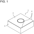
- the coated tool of the present disclosure includes a main surface in a substantially rectangular plate-like shape.
- the main surface is not limited to this shape.
- a coated tool 1 includes a first surface 2 (hereinafter described as a main surface 2) and a second surface 3 and includes a cutting edge 4 on at least a part of a portion where the first surface 2 and the second surface 3 intersect.
- the first surface 2 is a surface called a rake surface
- the second surface 3 is a surface called a flank surface.
- the cutting edge 4 is provided on at least a part of a portion where the rake surface 2 and the flank surface 3 intersect.
- the coated tool 1 includes a base member 5 and a coating layer 7 located on a surface of the base member 5.
- a material constituting the base member 5 of the coated tool 1 may be a hard alloy, a ceramic or a metal.
- the hard alloy may be a cemented carbide including tungsten carbide (WC) and an iron-group metal such as cobalt (Co) or nickel (Ni).
- Another hard alloy may be a Ti-based cermet including titanium carbonitride (TiCN) and iron-group metals such as cobalt (Co) or nickel (Ni).
- the ceramic may be Si 3 N 4 , Al 2 O 3 , diamond or cubic boron nitride (cBN) .
- the metal may be carbon steel, high-speed steel or alloy steel. If used as the coated tool 1, the base member 5 is favorably made of the cemented carbide or cermet among the materials described above in terms of fracture resistance and wear resistance.
- the coating layer 7 includes a TiCNO layer 9 and an Al 2 O 3 layer 11.
- the Al 2 O 3 layer 11 is in contact with the TiCNO layer 9 at a position of the TiCNO layer 9 far from the base member 5.
- the coated tool 1 of the present disclosure includes a first protrusion 13a projecting toward the Al 2 O 3 layer 11. Further, a second protrusion 13b is provided projecting from the first protrusion 13a in a direction intersecting a direction in which the first protrusion 13a projects.
- a protrusion including both the first protrusion 13a and the second protrusion 13b is referred to as a first composite protrusion 14a.
- the TiCNO layer 9 and the Al 2 O 3 layer 11 are less likely to peel off due to the engagement of the first protrusion 13a and the second protrusion 13b with the Al 2 O 3 layer 11.
- the second protrusion 13b is omitted, otherwise the figure would be complicated.
- Both the first protrusion 13a and the second protrusion 13b in the coated tool 1 of the present disclosure include Ti, C, N and O, and have homogeneous compositions.
- the first protrusion 13a and the second protrusion 13b having the homogeneous compositions, the first protrusion 13a and the second protrusion 13b are less likely to be cracked or broken, and the adhesion between the TiCNO layer 9 and the Al 2 O 3 layer 11 is improved as compared with a case where the first protrusion 13a and the second protrusion 13b have different compositions.
- That the first protrusion 13a and the second protrusion 13b have the homogeneous compositions means that the difference between the respective constituents is 5 % or less.
- composition deviation between the respective compositions of the first protrusion 13a and the second protrusion 13b may be 3 % or less.
- the deviation may be 1 % or less.
- the first protrusion 13a and the second protrusion 13b can be obtained by using the same gas when the first protrusion 13a and the second protrusion 13b are formed.
- the TiCNO layer 9 may include a plurality of second protrusions 13b on the first protrusion 13a.
- the first composite protrusion 14a may include a plurality of second protrusions 13b. This makes the TiCNO layer 9 and the Al 2 O 3 layer 11 even less likely to peel off. That the first protrusion 13a includes a plurality of second protrusions 13b means that one first protrusion 13a includes a plurality of second protrusions 13b.
- the second protrusion 13b may project in a direction toward the base member 5. That the second protrusion 13b projects in the direction toward the base member 5 means a state where an axis of the second protrusion 13b intersects the base member 5 when being extended, the axis connecting the apex of the second protrusion 13b and the midpoint of the width of a portion that is the origin of the projection of the second protrusion 13b in the cross-section as illustrated in Fig. 3 .
- the width of a portion of the first protrusion 13a may be larger than the width of the portion of the second protrusion 13b projecting from the first protrusion 13a, the portion being the origin of the projection from the first protrusion 13a.
- the length of the first protrusion 13a may be larger than the length of the second protrusion 13b projecting from the first protrusion 13a.
- the length of the first protrusion 13a means a distance between the apex of the first protrusion 13a and the midpoint of the width of the portion that is the origin of the projection of the first protrusion 13a.
- the length of the second protrusion 13b means a distance between the apex of the second protrusion 13b and the midpoint of the width of the portion that is the origin of the projection of the second protrusion 13b.
- the length of the second protrusion 13b may be 10 to 150 nm.
- the maximum width of the second protrusion 13b may be 50 nm or less.
- the TiCNO layer 9 may include a third protrusion 13c projecting from the second protrusion 13b in the direction intersecting a direction in which the second protrusion 13b projects.
- a protrusion including the first protrusion 13a, the second protrusion 13b, and the third protrusion 13c is referred to as a second composite protrusion 14b.
- the length of the third protrusion 13c may be shorter than the length of the second protrusion 13b. With such a structure, the first protrusion 13a and the second protrusion 13b are less likely to be broken, and the TiCNO layer 9 and the Al 2 O 3 layer 11 are less likely to peel off. As a result, the fracture resistance of the coated tool 1 is improved.
- the length of the third protrusion 13c may be 10 to 70 nm.
- the maximum width of the third protrusion 13c may be 20 nm or less.
- the length of the third protrusion 13c may be larger than the length of the second protrusion 13b.
- the first protrusion 13a may not be formed perpendicularly to the first surface 2 of the base member 5 but may be inclined relative to the first surface 2 of the base member 5.
- composition of the third protrusion 13c may be homogeneous to that of the second protrusion 13b.
- the composition deviation between the third protrusion 13c and the second protrusion 13b may be 5 % or less.
- the deviation may be 3 % or less.
- the deviation may be 1 % or less.
- the average width of the bases of the first protrusions 13a may be 40 to 200 nm.
- the average length of the first protrusions 13a may be 10 to 500 nm. Further, the average length of the first protrusions 13a may be 50 to 300 nm.
- the width of the base of the first protrusion 13a is the width of the portion that is the origin of the projection of the first protrusion 13a.
- the average value of the widths of the bases of the first protrusions 13a is the average value of widths of bases of 20 or more first protrusions 13a.
- the length of the first protrusion 13a means the distance between the apex of the first protrusion 13a and the midpoint of the width of the portion that is the origin of the projection of the first protrusion 13a.
- the average length of the first protrusions 13a is the average value of lengths of 20 or more first protrusions 13a.
- the length of the second protrusion 13b means a distance between the apex of the second protrusion 13b and the midpoint of the width of the portion that is the origin of the projection of the second protrusion 13b.
- the average width of the bases of the first protrusions 13a may be 60 to 120 nm.
- the average length of the first protrusions 13a may be 150 to 230 nm. If the first protrusion 13a has such a shape, the difference between the longest first protrusion 13a and the shortest first protrusion 13a becomes small. If the first protrusion parts 13a are relatively uniform as described above, the TiCNO layer 9 and the Al 2 O 3 layer 11 are even less likely to peel off.
- the average length of the first protrusions 13a may be four times or less the average width of the bases of the first protrusions 13a. With such a structure, the first protrusion 13a is less likely to be broken, so that the TiCNO layer 9 and the Al 2 O 3 layer 11 are even less likely to peel off.
- the average length of the first protrusions 13a may be three times or less the average width of the bases of the first protrusions 13a. As the ratio becomes smaller, the first protrusion 13a is less likely to be broken, so that the TiCNO layer 9 and the Al 2 O 3 layer 11 are even less likely to peel off.
- the average length of the first protrusions 13a may be 2.5 times or less the average width of the bases of the first protrusions 13a.
- the thickness of the TiCNO layer 9 is in the range of 10 nm to 35 nm, the hardness of the TiCNO layer 9 does not decrease, and the Al 2 O 3 layer 11 has an ⁇ -crystal structure.
- the thickness of the TiCNO layer 9 excludes the first protrusion 13a, the second protrusions 13b, and the third protrusions 13c.
- the TiCNO layer 9 may include, for example, 30 to 70 % by atom of titanium, 1 to 70 % by atom of carbon, 1 to 35 % by atom of nitrogen, and 3 to 20 % by atom of oxygen. Further, the TiCNO layer 9 may include 10 % by atom or less of aluminum. The TiCNO layer 9 may include 1 to 10 % by atom of a component such as chlorine or chromium. The TiCNO layer 9 may include other minor components.
- the TiCNO layer 9 and the first protrusion 13a, the second protrusion 13b, and the third protrusion 13c may all have the same composition and may be within the composition range described above.
- the ratio of the number of second composite protrusions 14b to the sum of the number of first composite protrusions 14a and the number of second composite protrusions 14b is 20 % or more in the cross-section orthogonal to the surface of the base member 5. With such a configuration, the coated tool 1 is excellent in impact resistance.
- the TiCNO layer 9 including the first protrusions 13a can be formed on the surface of the base member 5 by chemical vapor deposition (CVD) method under the following conditions.
- the base member 5 may be placed in a chamber of a film formation apparatus, and the TiCNO layer 9 may be formed by, for example, making the following settings: a film formation temperature is 900°C to 990°C, gas pressure is 5 kPa to 40 kPa, and a reactive gas composition is 3 % by volume to 15 % by volume of titanium tetrachloride (TiCl 4 ) gas, 3 % by volume to 10 % by volume of methane (CH 4 ) gas, 3 % by volume to 50 % by volume of nitrogen (N 2 ) gas, 0.5 % by volume to 2.0 % by volume of carbon monoxide (CO) gas, and the rest being hydrogen (H 2 ) gas.
- a film formation temperature is 900°C to 990°C
- gas pressure is 5 kPa to 40 kPa
- a reactive gas composition is 3 % by volume to 15 % by volume of titanium tetrachloride (TiCl 4 ) gas, 3
- the nitrogen (N 2 ) gas in the reactive gas composition is set to 30 % by volume to 50 % by volume, the average width of the bases of the first protrusions 13a tends to be wide and the average length of the first protrusions 13a tends to be short. In other words, under such a condition, it is easy to obtain the first protrusion 13a that is thick, short, and less likely to be broken.
- the film formation temperature is set to the range of 900 to 940°C by lowering the film formation temperature without changing the composition of the source gas, the second protrusion 13b is formed.
- the film formation time may be 30 to 90 minutes in total.
- the second protrusion 13b In the later stage of the formation of the TiCNO layer 9, that is, in the step of forming the second protrusions 13b, if the film formation time is extended, the number of second protrusions 13b increases, and the widths and lengths thereof tend to increase.
- the second protrusion 13b With its projecting direction extending toward the base member 5, is easily formed. In other words, the first composite protrusion 14a is easily formed. If the film formation time is further extended, the third protrusion 13c projecting from the second protrusion 13b is easily formed. In other words, the second composite protrusion 14b is easily formed.
- the Al 2 O 3 layer 11 can be formed by making the following settings: the film formation temperature is 900°C to 990°C, the gas pressure is 5 kPa to 20 kPa, and the composition of the reactive gas is 5 % by volume to 15 % by volume of aluminum trichloride (AlCl 3 ) gas, 0.5 % by volume to 2.5 % by volume of hydrogen chloride (HCl) gas, 0.5 % by volume to 5.0 % by volume of carbon dioxide (CO 2 ) gas, 0 % by volume to 1.0 % by volume of hydrogen sulfide (H 2 S) gas, and the rest being a hydrogen (H 2 ) gas.
- the Al 2 O 3 layer 11 may be made of ⁇ -alumina.
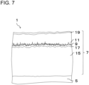
- the coating layer 7 may include a first TiCN layer 15 and a second TiCN layer 17 sequentially from the base member 5.
- the TiCNO layer 9 and the Al 2 O 3 layer 11 may be sequentially provided on the second TiCN layer 17.
- a surface layer 19 including Ti and N may further be provided on the Al 2 O 3 layer 11.
- the second protrusion 13b is omitted.
- the surface layer 19 may be made of other materials except for titanium nitride, such as titanium carbonitride, titanium oxycarbonitride, or chromium nitride.
- the surface layer 19 may be made of a colored material and have a function of easily discriminating whether or not the cutting edge 4 has been used.
- the surface layer 19 may be provided with a thickness of 0.1 um to 3.0 um.
- a base layer (not illustrated) made of TiN may further be provided between the base member 5 and the first TiCN layer 15.
- the base layer has a function of preventing the diffusion of these components into the layer present on the base layer.
- the base layer has a function of preventing the diffusion of these components into the layer present on the base layer.
- the first TiCN layer 15 is present on the base layer, the diffusion of the above components into the first TiCN layer 15 is prevented, and the lowering of the hardness of the first TiCN layer 15 is prevented.
- the carbon component in the base member 5 may be diffused into TiN of the base layer to form TiCN.
- the thickness of the base layer may be set to 0.1 um to 1.0 ⁇ m.
- the thickness of the first TiCN layer 15 may be set to 2 um to 15 um.
- the thickness of the second TiCN layer 17 may be set to 10 nm to 900 nm.
- the first TiCN layer 15 is made of a so-called moderate temperature (MT)-TiCN layer. If the thickness of the first TiCN layer 15 is 2 um to 15 um, which is formed by forming the MT-TiCN layer using a raw material that includes titanium tetrachloride (TiCl 4 ) gas, nitrogen (N 2 ) gas, acetonitrile (CH 3 CN) gas, or the like at a relatively low film formation temperature of 780°C to 880°C, the first TiCN layer 15 has high wear resistance and fracture resistance.
- MT moderate temperature
- the first titanium carbonitride crystal included in the first TiCN layer 15 may be a columnar crystal elongated in the thickness direction of the coating layer 7.
- the second TiCN layer 17 is made of a so-called high temperature (HT)-TiCN layer.
- the HT-TiCN layer may be formed using titanium tetrachloride (TiCl 4 ) gas, nitrogen (N 2 ) gas, methane (CH 4 ) gas, or the like as a source gas and not including acetonitrile (CH 3 CN) gas at a film formation temperature in the range of 900°C to 1050°C.
- the film may be formed at a higher temperature than the first TiCN layer 15.
- the thickness of the second TiCN layer 17 may be from 10 nm to 900 nm.
- an interface layer (not illustrated) may be disposed between the first TiCN layer 15 and the second TiCN layer 17, the interface layer including 30 to 70 % by atom of titanium, 15 to 35 % by atom of carbon, 15 to 35 % by atom of nitrogen, and 2 to 10 % by atom of oxygen.
- the thickness of the interface layer may be from 5 nm to 50 nm.
- a method may be used in which after the formation of the first TiCN layer 15, the film formation chamber is temporarily cooled, a sample is removed into the atmosphere, and then the sample is placed again in the film formation chamber to heat the film formation chamber, thereby forming the second TiCN layer 17.
- the carbon content ratio to the total content of carbon and nitrogen included in the second TiCN layer 17 may be smaller than the carbon content ratio of the first TiCN layer 15. This leads to improvement in the hardness of the first TiCN layer 15. As a result, the wear resistance and the fracture resistance of the coating layer 7 are improved.
- the carbon content ratio is the ratio (C/(C + N)) of the content of carbon to the total content of carbon (C) and nitrogen (N) included.
- the wear resistance and the fracture resistance of the coating layer 7 are further improved. If the carbon content in the first TiCN layer 15 is set to 15 to 29 % by atom and the nitrogen content is set to 22 to 35 % by atom, the wear resistance and the fracture resistance of the coating layer 7 are further enhanced. If the carbon content of the second TiCN layer 17 is set to 13 to 24 % by atom and the nitrogen content is set to 23 to 35 % by atom, the adhesion between the second TiCN layer 17 and the Al 2 O 3 layer 11 is enhanced.
- the first TiCN layer 15 includes 45 to 60 % by atom of titanium, 15 to 29 % by atom of carbon, and 22 to 35 % by atom of nitrogen, the wear resistance and the fracture resistance of the coating layer 7 are higher.
- the first TiCN layer 15 may include 0.5 % or less by atom of oxygen.
- the second TiCN layer 17 includes 48 to 60 % by atom of titanium, 10 to 20 % by atom of carbon, and 15 to 25 % by atom of nitrogen, the second TiCN layer 17 is not broken, and the adhesion between the second TiCN layer 17 and the Al 2 O 3 layer 11 is high.
- the second TiCN layer 17 may include 1 to 10 % by atom of oxygen.
- oxygen may be present in the first TiCN layer 15 and the second TiCN layer 17, and the oxygen present in the second TiCN layer 17 may be more than the oxygen present in the first TiCN layer 15.
- the carbon content and the nitrogen content in each of the first TiCN layer 15 and the second TiCN layer 17 are measured using an energy dispersive X-ray spectrometer (EDS) accompanying a transmission electron microscope (TEM).
- EDS energy dispersive X-ray spectrometer
- TEM transmission electron microscope
- each layer and the shape of a crystal constituting each layer are measurable by observing an electron microscope photograph (scanning electron microscope (SEM) photograph or transmission electron microscope (TEM) photograph) in a cross-section of the tool 1.
- SEM scanning electron microscope
- TEM transmission electron microscope
- the coated tool 1 is designed to perform a cutting process by bringing the cutting edge, formed at an intersection between the rake surface and the flank surface, into contact with a workpiece and can produce the excellent effects described above.
- the coated tool 1 of the present disclosure can be applied to various uses such as wear-resistant parts like sliding parts and molds, excavation tools, tools like edge tools, and impact-resistant parts, and in these cases as well, the coated tool 1 has excellent mechanical reliability.
- metal powder, carbon powder, or the like is suitably added to inorganic powder of carbide, nitride, carbonitride, oxide or the like, which can form a hard alloy constituting the base member by sintering, and these are mixed together, to prepare a mixed powder.
- the mixed powder is used to be molded into a predetermined tool shape by a known molding method such as press-molding, casting molding, extrusion molding and cold isostatic pressing.
- the molded body is sintered in a vacuum or a non-oxidizing atmosphere to produce the base member described above.
- the surface of the base member is then subjected to a polishing process, and a cutting part is subjected to a honing process if desired.
- a coating layer is deposited on the surface by chemical vapor deposition (CVD) method.
- a base member is placed in the chamber, and a TiN layer as a base layer is formed.
- the layer is formed by making the following settings: the film formation temperature is 800°C to 940°C, the gas pressure is 8 kPa to 50 kPa, and the composition of the reactive gas is 0.5 % by volume to 10 % by volume of titanium tetrachloride (TiCl 4 ) gas, 10 % by volume to 60 % by volume of nitrogen (N 2 ) gas, and the rest being hydrogen (H 2 ) gas.
- TiCl 4 titanium tetrachloride
- a first TiCN layer is formed.
- the layer is formed by making the following settings: the film formation temperature is 780°C to 880°C, the gas pressure is 5 kPa to 25 kPa, and the composition of the reactive gas is 0.5 % by volume to 10 % by volume of titanium tetrachloride (TiCl 4 ) gas, 5 % by volume to 60 % by volume of nitrogen (N 2 ) gas, 0.1 % by volume to 3.0 % by volume of acetonitrile (CH 3 CN) gas, and the rest being hydrogen (H 2 ) gas.
- TiCl 4 titanium tetrachloride
- N 2 nitrogen
- CH 3 CN acetonitrile
- a mean crystal width of columnar crystals of titanium carbonitride constituting the first TiCN layer can be made larger on the side of the surface than on the side of the base member by increasing the content ratio of the acetonitrile (CH 3 CN) gas in a later stage of the film formation than in an initial stage of the film formation.
- CH 3 CN acetonitrile
- an interface layer is formed on the first TiCN layer.
- the layer is formed by making the following settings: the film formation temperature is 900°C to 1050°C, the gas pressure is 5 kPa to 40 kPa, and the composition of the reactive gas is 3 % by volume to 30 % by volume of titanium tetrachloride (TiCl 4 ) gas, 3 % by volume to 15 % by volume of methane (CH 4 ) gas, 5 % by volume to 10 % by volume of nitrogen (N 2 ) gas, 0.5 % by volume to 10 % by volume of carbon dioxide (CO 2 ) gas, and the rest being hydrogen (H 2 ) gas.
- TiCl 4 titanium tetrachloride
- a second TiCN layer is formed.
- the layer is formed by making the following settings: the film formation temperature is 900°C to 990°C, the gas pressure is 5 kPa to 40 kPa, and the composition of the reactive gas is 1 % by volume to 4 % by volume of titanium tetrachloride (TiCl 4 ) gas, 5 % by volume to 20 % by volume of nitrogen (N 2 ) gas, 0.1 % by volume to 10 % by volume of methane (CH 4 ) gas, and the rest being hydrogen (H 2 ) gas.
- TiCl 4 titanium tetrachloride
- a TiCNO layer 9 is formed.
- the layer is formed by making the following settings: the film formation temperature is 940°C to 990°C, the gas pressure is 5 kPa to 40 kPa, and the composition of the reactive gas is 3 % by volume to 15 % by volume of titanium tetrachloride (TiCl 4 ) gas, 3 % by volume to 10 % by volume of methane (CH 4 ) gas, 3 % by volume to 50 % by volume of nitrogen (N 2 ) gas, 0.5 % by volume to 2.0 % by volume of carbon oxide (CO) gas, and the rest being hydrogen (H 2 ) gas.
- TiCl 4 titanium tetrachloride
- CH 4 methane
- N 2 nitrogen
- CO carbon oxide
- the film formation temperature is lowered to 900 to 940°C, and the layer is formed so that the total time is 30 to 90 minutes.
- an Al 2 O 3 layer is formed.
- the Al 2 O 3 layer is formed by making the following settings: the film formation temperature is 950°C to 1100°C, the gas pressure is 5 kPa to 20 kPa, and the composition of the reactive gas is 5 % by volume to 15 % by volume of aluminum trichloride (AlCl 3 ) gas, 0.5 % by volume to 2.5 % by volume of hydrogen chloride (HCl) gas, 0.5 % by volume to 5.0 % by volume of carbon dioxide (CO 2 ) gas, 0 % by volume to 1.0 % by volume of hydrogen sulfide (H 2 S) gas, and the rest being hydrogen (H 2 ) gas.
- AlCl 3 aluminum trichloride
- HCl hydrogen chloride
- CO 2 carbon dioxide
- H 2 S hydrogen sulfide
- a TiN layer which is a surface layer is formed.
- the layer is formed by making the following settings: the film formation temperature is 960°C to 1100°C, the gas pressure is 10 kPa to 85 kPa, and the reactive gas composition is 0.1 % by volume to 10 % by volume of titanium tetrachloride (TiCl 4 ) gas, 10 % by volume to 60 % by volume of nitrogen (N 2 ) gas, and the rest being hydrogen (H 2 ) gas.
- TiCl 4 titanium tetrachloride
- the polishing process is performed on at least a cutting part of the surface of the formed coating layer if desired.
- the cutting part is smoothly processed to prevent the welding of the workpiece, and a tool with more excellent fracture resistance is obtained.
- the example has been shown where the first TiCN layer, the second TiCN layer, and the surface layer are provided, but the TiCNO layer and the Al 2 O 3 layer may be directly laminated on the surface of the base member.
- the coated tool 1 of the present disclosure has been described above, the present disclosure is not limited to the embodiment described above, and various improvements and modifications may be made within a range not departing from the gist of the present disclosure.
- a cutting tool 101 of the present disclosure is, for example, a rod-shaped body extending from a first end (the upper end in Fig. 8 ) toward a second end (the lower end in Fig. 8 ).
- the cutting tool 101 includes a holder 105 including a pocket 103 on a first end side (tip side), and the coated tool 1 located in the pocket 103. Because including the coated tool 1, the cutting tool 101 can perform a stable cutting process over a long period of time.
- the pocket 103 is a part that permits attachment of the coated tool 1.
- the pocket 103 includes a seating surface parallel to a lower surface of the holder 105, and a constraining side surface inclined relative to the seating surface.
- the pocket 103 opens into a side of the first end of the holder 105.
- the coated tool 1 is located in the pocket 103. At this time, the lower surface of the coated tool 1 may be in direct contact with the pocket 103, or a sheet (not illustrated) may be disposed between the coated tool 1 and the pocket 103.
- the coated tool 1 is mounted on the holder 105 such that at least a part of a portion used as a cutting edge 4 at a ridge line where the first surface 3 and the second surface 5 intersect projects outward from the holder 105.
- the coated tool 1 is attached to the holder 105 with a fixing screw 107. That is, the coated tool 1 is attached to the holder 105 by inserting the fixing screw 107 into a through hole 17 of the coated tool 1, inserting the tip of the fixing screw 107 into a screw hole (not illustrated) formed in the pocket 103, and screwing the screw parts together.
- steel cast iron or the like
- steel having high toughness may be used.
- a cutting tool 101 used for a so-called turning process is exemplified.
- the turning process include an inner-diameter process, an outer-diameter process, and grooving process.
- the cutting tool 101 is not limited to a tool used for the turning process.
- the coated tools 1 of the above embodiment are applicable to the cutting tools for use in the milling process.
- an amount of 6 % by mass of metal cobalt powder having a mean particle diameter of 1.2 um, an amount of 0.5 % by mass of titanium carbide powder having a mean particle diameter of 2.0 um, an amount of 5 % by mass of niobium carbide powder having a mean particle diameter of 2.0 ⁇ m, and the rest, namely, tungsten carbide powder having a mean particle diameter of 1.5 um were added and mixed together.
- the manufactured base member was then subjected to a brushing process, and a part of the base member which served as a cutting edge was subjected to round honing.
- the coating layer was formed on the above base member of cemented carbide by combining individual film formation conditions shown in Table 1 by chemical vapor deposition (CVD) method as described in Tables 2 and 3, thereby manufacturing a coated tool.
- CVD chemical vapor deposition
- the cross-section including the coating layer of the sample was subjected to SEM observation to observe the presence or absence of the first protrusion, the second protrusion, and the third protrusion and the forms of the first protrusion, the second protrusion and the third protrusion.
- Tables 2 and 3 show the ratio of the number of first composite protrusions to the sum of the number of first composite protrusions and the number of second composite protrusions and the ratio of the number of second composite protrusions. Then, an intermittent cutting test was conducted using the obtained coated tool under the following conditions to evaluate the fracture resistance. Tables 2 and 3 show the test results.
- Table 2 describes how many times the number of impact times of Sample No. 1 each sample withstood, based on the number of impact times of Sample No. 1.
- Table 3 describes how many times the number of impact times of Sample No. 8 each sample withstood, based on the number of impact times of Sample No. 8.
- Samples No. 9 to 14 including the first composite protrusion that includes the second protrusion the cutting performance is more excellent than in Sample No. 8.
- Samples No. 11 and (inventive) No. 14 including the second composite protrusion that includes the third protrusion more excellent cutting performance was obtained.
- the coated tool of the present disclosure has cutting performance superior to that of the sample without the second protrusion, that is, the first composite protrusion.
Landscapes
- Chemical & Material Sciences (AREA)
- Engineering & Computer Science (AREA)
- Mechanical Engineering (AREA)
- Chemical Kinetics & Catalysis (AREA)
- Materials Engineering (AREA)
- Metallurgy (AREA)
- Organic Chemistry (AREA)
- Inorganic Chemistry (AREA)
- General Chemical & Material Sciences (AREA)
- Ceramic Engineering (AREA)
- Chemical Vapour Deposition (AREA)
- Cutting Tools, Boring Holders, And Turrets (AREA)
Claims (7)
- Outil revêtu (1), comprenant :un élément de base (5) ; etune couche de revêtement (7) située sur une surface de l'élément de base (5),dans lequella couche de revêtement (7) comprend une couche TiCNO (9) et une couche Al2O3 (11),la couche Al2O3 (11) est située en contact avec la couche TiCNO (9) à une position plus éloignée de l'élément de base (5) que la couche TiCNO (9),la couche TiCNO (9) comprend une première saillie composite (14a) comprenant une première saillie (13a) qui fait saillie vers la couche Al2O3 (11) et une deuxième saillie (13b) qui fait saillie à partir de la première saillie (13a) dans une direction coupant une direction dans laquelle la première saillie fait saillie (13a),la couche TiCNO (9) comprend une deuxième saillie composite (14b) comprenant une troisième saillie (13c) qui fait saillie à partir de la deuxième saillie (13b) dans une direction coupant la direction dans laquelle la deuxième saillie fait saillie (13b), etun rapport du nombre des deuxièmes saillies composites (14b) à une somme du nombre des premières saillies composites (14a) et du nombre des deuxièmes saillies composites (14b) est de 20 % ou plus en une section transversale orthogonale à la surface de l'élément de base (5) .
- Outil revêtu (1) selon la revendication 1, dans lequel la première saillie composite comprend (14a) une pluralité de deuxièmes saillies (13b).
- Outil revêtu (1) selon la revendication 1 ou 2, dans lequel la deuxième saillie (13b) fait saillie en une direction vers l'élément de base (5).
- Outil revêtu (1) selon l'une quelconque des revendications 1 à 3, dans lequel une largeur moyenne de bases des premières saillies (13a) est de 40 à 200 nm, et une longueur moyenne des premières saillies (13a) est de 50 à 300 nm en une section transversale orthogonale à la surface de l'élément de base (5).
- Outil revêtu (1) selon l'une quelconque des revendications 1 à 4, dans lequel une longueur moyenne des premières saillies (13a) est trois fois ou moins une largeur moyenne de bases des premières saillies (13a).
- Outil revêtu (1) selon l'une quelconque des revendications 1 à 5, dans lequel la couche de revêtement (7) comprend une première couche TiCN (15), une deuxième couche TiCN (17), la couche TiCNO (9) et la couche Al2O3 (11) séquentiellement à partir de l'élément de base (5).
- Outil de coupe (101), comprenant :un support (105) s'étendant d'une première extrémité vers une deuxième extrémité et comprenant une poche (103) sur un côté de la première extrémité ; etl'outil revêtu (1) selon l'une quelconque des revendications 1 à 6, l'outil revêtu (1) étant situé dans la poche (103).
Applications Claiming Priority (3)
| Application Number | Priority Date | Filing Date | Title |
|---|---|---|---|
| JP2018012339 | 2018-01-29 | ||
| JP2018065105 | 2018-03-29 | ||
| PCT/JP2019/002768 WO2019146784A1 (fr) | 2018-01-29 | 2019-01-28 | Outil revêtu, et outil de coupe équipé de celui-ci |
Publications (3)
| Publication Number | Publication Date |
|---|---|
| EP3747577A1 EP3747577A1 (fr) | 2020-12-09 |
| EP3747577A4 EP3747577A4 (fr) | 2021-07-07 |
| EP3747577B1 true EP3747577B1 (fr) | 2024-01-24 |
Family
ID=67395027
Family Applications (1)
| Application Number | Title | Priority Date | Filing Date |
|---|---|---|---|
| EP19744169.4A Active EP3747577B1 (fr) | 2018-01-29 | 2019-01-28 | Outil revêtu et outil de coupe équipé de celui-ci |
Country Status (6)
| Country | Link |
|---|---|
| US (1) | US11534835B2 (fr) |
| EP (1) | EP3747577B1 (fr) |
| JP (1) | JP7037580B2 (fr) |
| KR (1) | KR102492360B1 (fr) |
| CN (1) | CN111867761B (fr) |
| WO (1) | WO2019146784A1 (fr) |
Families Citing this family (4)
| Publication number | Priority date | Publication date | Assignee | Title |
|---|---|---|---|---|
| CN114173968B (zh) * | 2019-07-29 | 2024-10-29 | 京瓷株式会社 | 涂层刀具和具备它的切削刀具 |
| EP4005708A4 (fr) * | 2019-07-29 | 2022-11-30 | Kyocera Corporation | Outil revêtu et outil de coupe doté dudit outil |
| US12479032B2 (en) * | 2020-06-30 | 2025-11-25 | Kyocera Corporation | Coated tool and cutting tool |
| WO2025227171A1 (fr) * | 2024-04-16 | 2025-11-06 | Boehlerit Gmbh & Co.Kg. | Insert de coupe revêtu d'une couche de revêtement comprenant de l'oxyde d'aluminium et du carbonitrure de titane |
Family Cites Families (18)
| Publication number | Priority date | Publication date | Assignee | Title |
|---|---|---|---|---|
| CA968908A (en) | 1971-07-29 | 1975-06-10 | Photocircuits Division Of Kollmorgen Corporation | Sensitized substrates for chemical metallization |
| JP3250134B2 (ja) * | 1995-12-25 | 2002-01-28 | 三菱マテリアル株式会社 | 耐チッピング性のすぐれた表面被覆超硬合金製切削工具 |
| JP3962300B2 (ja) * | 2002-08-13 | 2007-08-22 | 日立ツール株式会社 | 酸化アルミニウム被覆工具 |
| JP4711714B2 (ja) * | 2005-03-30 | 2011-06-29 | 京セラ株式会社 | 表面被覆切削工具 |
| JP2007229821A (ja) * | 2006-02-27 | 2007-09-13 | Kyocera Corp | 表面被覆切削工具 |
| JP2008296292A (ja) * | 2007-05-29 | 2008-12-11 | Mitsubishi Materials Corp | 硬質被覆層がすぐれた耐欠損性を発揮する表面被覆切削工具 |
| JP5303732B2 (ja) | 2008-01-21 | 2013-10-02 | 日立ツール株式会社 | 被覆工具 |
| JP5321094B2 (ja) * | 2009-01-30 | 2013-10-23 | 三菱マテリアル株式会社 | 表面被覆切削工具 |
| KR101104493B1 (ko) * | 2009-06-17 | 2012-01-12 | 한국야금 주식회사 | 절삭공구 또는 내마모성 공구용 표면 피복 박막 |
| KR101297298B1 (ko) * | 2011-06-03 | 2013-08-16 | 한국야금 주식회사 | 절삭공구용 코팅층 |
| JP5257535B2 (ja) * | 2011-08-31 | 2013-08-07 | 三菱マテリアル株式会社 | 表面被覆切削工具 |
| JP5841170B2 (ja) * | 2011-11-29 | 2016-01-13 | 京セラ株式会社 | 被覆工具 |
| CN104271291B (zh) * | 2012-04-19 | 2016-08-17 | 住友电工硬质合金株式会社 | 表面被覆切削工具 |
| JP2014121740A (ja) * | 2012-12-20 | 2014-07-03 | Mitsubishi Materials Corp | 重切削加工で、硬質被覆層がすぐれた耐剥離性を発揮する表面被覆切削工具 |
| CN105828991B (zh) * | 2013-12-17 | 2017-12-01 | 京瓷株式会社 | 涂层工具 |
| CN105269010B (zh) * | 2014-06-30 | 2017-08-04 | 株洲钻石切削刀具股份有限公司 | 改善涂层结构的切削刀片及其制备方法 |
| KR102089996B1 (ko) | 2015-11-28 | 2020-03-17 | 쿄세라 코포레이션 | 절삭 공구 |
| KR102176903B1 (ko) | 2016-02-24 | 2020-11-10 | 교세라 가부시키가이샤 | 피복 공구 |
-
2019
- 2019-01-28 WO PCT/JP2019/002768 patent/WO2019146784A1/fr not_active Ceased
- 2019-01-28 EP EP19744169.4A patent/EP3747577B1/fr active Active
- 2019-01-28 JP JP2019567205A patent/JP7037580B2/ja active Active
- 2019-01-28 CN CN201980020426.4A patent/CN111867761B/zh active Active
- 2019-01-28 US US16/963,936 patent/US11534835B2/en active Active
- 2019-01-28 KR KR1020207024570A patent/KR102492360B1/ko active Active
Also Published As
| Publication number | Publication date |
|---|---|
| EP3747577A4 (fr) | 2021-07-07 |
| WO2019146784A1 (fr) | 2019-08-01 |
| CN111867761B (zh) | 2023-04-28 |
| JP7037580B2 (ja) | 2022-03-16 |
| EP3747577A1 (fr) | 2020-12-09 |
| CN111867761A (zh) | 2020-10-30 |
| JPWO2019146784A1 (ja) | 2021-01-28 |
| US11534835B2 (en) | 2022-12-27 |
| US20210114114A1 (en) | 2021-04-22 |
| KR20200111769A (ko) | 2020-09-29 |
| KR102492360B1 (ko) | 2023-01-27 |
Similar Documents
| Publication | Publication Date | Title |
|---|---|---|
| EP3747575B1 (fr) | Outil revêtu, et outil de coupe équipé de celui-ci | |
| CN101790594B (zh) | Ti基金属陶瓷及被覆金属陶瓷以及切削工具 | |
| EP2006040B1 (fr) | Outil de découpage, procédé de production dudit outil de découpage et procédé de découpage | |
| EP2251122A1 (fr) | Organe à surface revêtue et outil de coupe | |
| EP2839907B1 (fr) | Outil de coupe à revêtement de surface | |
| EP3747577B1 (fr) | Outil revêtu et outil de coupe équipé de celui-ci | |
| EP4005709A1 (fr) | Outil revêtu, et outil de coupe le comprenant | |
| CN115315330B (zh) | 涂层刀具 | |
| US11541468B2 (en) | Coated tool and cutting tool including same | |
| EP4005710A1 (fr) | Outil revêtu et outil de coupe comprenant un tel outil revêtu | |
| EP4005711A1 (fr) | Outil revêtu, et outil de coupe le comprenant | |
| US20260027625A1 (en) | Coated tool and cutting tool | |
| US11839923B2 (en) | Coated tool, cutting tool, and method for manufacturing machined product | |
| CN113165083B (zh) | 涂层刀具和具备它的切削刀具 | |
| WO2025197502A1 (fr) | Outil revêtu et outil de coupe | |
| WO2024181016A1 (fr) | Carbure cémenté, outil revêtu et outil de coupe | |
| JP2005153099A (ja) | 表面被覆切削工具 | |
| JP2008207286A (ja) | 耐摩耗性部材およびそれを用いてなる切削工具 | |
| CN113165082A (zh) | 涂层刀具及具备该涂层刀具的切削刀具 |
Legal Events
| Date | Code | Title | Description |
|---|---|---|---|
| STAA | Information on the status of an ep patent application or granted ep patent |
Free format text: STATUS: THE INTERNATIONAL PUBLICATION HAS BEEN MADE |
|
| PUAI | Public reference made under article 153(3) epc to a published international application that has entered the european phase |
Free format text: ORIGINAL CODE: 0009012 |
|
| STAA | Information on the status of an ep patent application or granted ep patent |
Free format text: STATUS: REQUEST FOR EXAMINATION WAS MADE |
|
| 17P | Request for examination filed |
Effective date: 20200825 |
|
| AK | Designated contracting states |
Kind code of ref document: A1 Designated state(s): AL AT BE BG CH CY CZ DE DK EE ES FI FR GB GR HR HU IE IS IT LI LT LU LV MC MK MT NL NO PL PT RO RS SE SI SK SM TR |
|
| AX | Request for extension of the european patent |
Extension state: BA ME |
|
| DAV | Request for validation of the european patent (deleted) | ||
| DAX | Request for extension of the european patent (deleted) | ||
| A4 | Supplementary search report drawn up and despatched |
Effective date: 20210608 |
|
| RIC1 | Information provided on ipc code assigned before grant |
Ipc: B23B 27/14 20060101AFI20210601BHEP Ipc: C23C 16/30 20060101ALI20210601BHEP Ipc: C23C 16/40 20060101ALI20210601BHEP Ipc: C23C 28/04 20060101ALI20210601BHEP Ipc: C23C 30/00 20060101ALI20210601BHEP Ipc: C23C 16/00 20060101ALI20210601BHEP |
|
| P01 | Opt-out of the competence of the unified patent court (upc) registered |
Effective date: 20230508 |
|
| REG | Reference to a national code |
Ref country code: DE Ref legal event code: R079 Free format text: PREVIOUS MAIN CLASS: B23B0027140000 Ipc: C23C0016300000 Ref document number: 602019045598 Country of ref document: DE |
|
| GRAP | Despatch of communication of intention to grant a patent |
Free format text: ORIGINAL CODE: EPIDOSNIGR1 |
|
| STAA | Information on the status of an ep patent application or granted ep patent |
Free format text: STATUS: GRANT OF PATENT IS INTENDED |
|
| RIC1 | Information provided on ipc code assigned before grant |
Ipc: C23C 30/00 20060101ALI20230922BHEP Ipc: C23C 28/04 20060101ALI20230922BHEP Ipc: C23C 16/455 20060101ALI20230922BHEP Ipc: C23C 16/36 20060101ALI20230922BHEP Ipc: C23C 16/30 20060101AFI20230922BHEP |
|
| INTG | Intention to grant announced |
Effective date: 20231018 |
|
| GRAS | Grant fee paid |
Free format text: ORIGINAL CODE: EPIDOSNIGR3 |
|
| GRAA | (expected) grant |
Free format text: ORIGINAL CODE: 0009210 |
|
| STAA | Information on the status of an ep patent application or granted ep patent |
Free format text: STATUS: THE PATENT HAS BEEN GRANTED |
|
| AK | Designated contracting states |
Kind code of ref document: B1 Designated state(s): AL AT BE BG CH CY CZ DE DK EE ES FI FR GB GR HR HU IE IS IT LI LT LU LV MC MK MT NL NO PL PT RO RS SE SI SK SM TR |
|
| REG | Reference to a national code |
Ref country code: GB Ref legal event code: FG4D |
|
| REG | Reference to a national code |
Ref country code: CH Ref legal event code: EP |
|
| REG | Reference to a national code |
Ref country code: DE Ref legal event code: R096 Ref document number: 602019045598 Country of ref document: DE |
|
| REG | Reference to a national code |
Ref country code: IE Ref legal event code: FG4D |
|
| REG | Reference to a national code |
Ref country code: LT Ref legal event code: MG9D |
|
| REG | Reference to a national code |
Ref country code: NL Ref legal event code: MP Effective date: 20240124 |
|
| PG25 | Lapsed in a contracting state [announced via postgrant information from national office to epo] |
Ref country code: NL Free format text: LAPSE BECAUSE OF FAILURE TO SUBMIT A TRANSLATION OF THE DESCRIPTION OR TO PAY THE FEE WITHIN THE PRESCRIBED TIME-LIMIT Effective date: 20240124 |
|
| PG25 | Lapsed in a contracting state [announced via postgrant information from national office to epo] |
Ref country code: NL Free format text: LAPSE BECAUSE OF FAILURE TO SUBMIT A TRANSLATION OF THE DESCRIPTION OR TO PAY THE FEE WITHIN THE PRESCRIBED TIME-LIMIT Effective date: 20240124 |
|
| PG25 | Lapsed in a contracting state [announced via postgrant information from national office to epo] |
Ref country code: IS Free format text: LAPSE BECAUSE OF FAILURE TO SUBMIT A TRANSLATION OF THE DESCRIPTION OR TO PAY THE FEE WITHIN THE PRESCRIBED TIME-LIMIT Effective date: 20240524 |
|
| PG25 | Lapsed in a contracting state [announced via postgrant information from national office to epo] |
Ref country code: LT Free format text: LAPSE BECAUSE OF FAILURE TO SUBMIT A TRANSLATION OF THE DESCRIPTION OR TO PAY THE FEE WITHIN THE PRESCRIBED TIME-LIMIT Effective date: 20240124 |
|
| PG25 | Lapsed in a contracting state [announced via postgrant information from national office to epo] |
Ref country code: GR Free format text: LAPSE BECAUSE OF FAILURE TO SUBMIT A TRANSLATION OF THE DESCRIPTION OR TO PAY THE FEE WITHIN THE PRESCRIBED TIME-LIMIT Effective date: 20240425 |
|
| REG | Reference to a national code |
Ref country code: AT Ref legal event code: MK05 Ref document number: 1652269 Country of ref document: AT Kind code of ref document: T Effective date: 20240124 |
|
| PG25 | Lapsed in a contracting state [announced via postgrant information from national office to epo] |
Ref country code: RS Free format text: LAPSE BECAUSE OF FAILURE TO SUBMIT A TRANSLATION OF THE DESCRIPTION OR TO PAY THE FEE WITHIN THE PRESCRIBED TIME-LIMIT Effective date: 20240424 Ref country code: HR Free format text: LAPSE BECAUSE OF FAILURE TO SUBMIT A TRANSLATION OF THE DESCRIPTION OR TO PAY THE FEE WITHIN THE PRESCRIBED TIME-LIMIT Effective date: 20240124 |
|
| PG25 | Lapsed in a contracting state [announced via postgrant information from national office to epo] |
Ref country code: ES Free format text: LAPSE BECAUSE OF FAILURE TO SUBMIT A TRANSLATION OF THE DESCRIPTION OR TO PAY THE FEE WITHIN THE PRESCRIBED TIME-LIMIT Effective date: 20240124 |
|
| PG25 | Lapsed in a contracting state [announced via postgrant information from national office to epo] |
Ref country code: AT Free format text: LAPSE BECAUSE OF FAILURE TO SUBMIT A TRANSLATION OF THE DESCRIPTION OR TO PAY THE FEE WITHIN THE PRESCRIBED TIME-LIMIT Effective date: 20240124 |
|
| PG25 | Lapsed in a contracting state [announced via postgrant information from national office to epo] |
Ref country code: RS Free format text: LAPSE BECAUSE OF FAILURE TO SUBMIT A TRANSLATION OF THE DESCRIPTION OR TO PAY THE FEE WITHIN THE PRESCRIBED TIME-LIMIT Effective date: 20240424 Ref country code: NO Free format text: LAPSE BECAUSE OF FAILURE TO SUBMIT A TRANSLATION OF THE DESCRIPTION OR TO PAY THE FEE WITHIN THE PRESCRIBED TIME-LIMIT Effective date: 20240424 Ref country code: LT Free format text: LAPSE BECAUSE OF FAILURE TO SUBMIT A TRANSLATION OF THE DESCRIPTION OR TO PAY THE FEE WITHIN THE PRESCRIBED TIME-LIMIT Effective date: 20240124 Ref country code: IS Free format text: LAPSE BECAUSE OF FAILURE TO SUBMIT A TRANSLATION OF THE DESCRIPTION OR TO PAY THE FEE WITHIN THE PRESCRIBED TIME-LIMIT Effective date: 20240524 Ref country code: HR Free format text: LAPSE BECAUSE OF FAILURE TO SUBMIT A TRANSLATION OF THE DESCRIPTION OR TO PAY THE FEE WITHIN THE PRESCRIBED TIME-LIMIT Effective date: 20240124 Ref country code: GR Free format text: LAPSE BECAUSE OF FAILURE TO SUBMIT A TRANSLATION OF THE DESCRIPTION OR TO PAY THE FEE WITHIN THE PRESCRIBED TIME-LIMIT Effective date: 20240425 Ref country code: FI Free format text: LAPSE BECAUSE OF FAILURE TO SUBMIT A TRANSLATION OF THE DESCRIPTION OR TO PAY THE FEE WITHIN THE PRESCRIBED TIME-LIMIT Effective date: 20240124 Ref country code: ES Free format text: LAPSE BECAUSE OF FAILURE TO SUBMIT A TRANSLATION OF THE DESCRIPTION OR TO PAY THE FEE WITHIN THE PRESCRIBED TIME-LIMIT Effective date: 20240124 Ref country code: BG Free format text: LAPSE BECAUSE OF FAILURE TO SUBMIT A TRANSLATION OF THE DESCRIPTION OR TO PAY THE FEE WITHIN THE PRESCRIBED TIME-LIMIT Effective date: 20240124 Ref country code: AT Free format text: LAPSE BECAUSE OF FAILURE TO SUBMIT A TRANSLATION OF THE DESCRIPTION OR TO PAY THE FEE WITHIN THE PRESCRIBED TIME-LIMIT Effective date: 20240124 |
|
| PG25 | Lapsed in a contracting state [announced via postgrant information from national office to epo] |
Ref country code: PT Free format text: LAPSE BECAUSE OF FAILURE TO SUBMIT A TRANSLATION OF THE DESCRIPTION OR TO PAY THE FEE WITHIN THE PRESCRIBED TIME-LIMIT Effective date: 20240524 Ref country code: PL Free format text: LAPSE BECAUSE OF FAILURE TO SUBMIT A TRANSLATION OF THE DESCRIPTION OR TO PAY THE FEE WITHIN THE PRESCRIBED TIME-LIMIT Effective date: 20240124 |
|
| PG25 | Lapsed in a contracting state [announced via postgrant information from national office to epo] |
Ref country code: SE Free format text: LAPSE BECAUSE OF FAILURE TO SUBMIT A TRANSLATION OF THE DESCRIPTION OR TO PAY THE FEE WITHIN THE PRESCRIBED TIME-LIMIT Effective date: 20240124 Ref country code: PT Free format text: LAPSE BECAUSE OF FAILURE TO SUBMIT A TRANSLATION OF THE DESCRIPTION OR TO PAY THE FEE WITHIN THE PRESCRIBED TIME-LIMIT Effective date: 20240524 Ref country code: PL Free format text: LAPSE BECAUSE OF FAILURE TO SUBMIT A TRANSLATION OF THE DESCRIPTION OR TO PAY THE FEE WITHIN THE PRESCRIBED TIME-LIMIT Effective date: 20240124 Ref country code: LV Free format text: LAPSE BECAUSE OF FAILURE TO SUBMIT A TRANSLATION OF THE DESCRIPTION OR TO PAY THE FEE WITHIN THE PRESCRIBED TIME-LIMIT Effective date: 20240124 |
|
| REG | Reference to a national code |
Ref country code: CH Ref legal event code: PL |
|
| PG25 | Lapsed in a contracting state [announced via postgrant information from national office to epo] |
Ref country code: LU Free format text: LAPSE BECAUSE OF NON-PAYMENT OF DUE FEES Effective date: 20240128 |
|
| PG25 | Lapsed in a contracting state [announced via postgrant information from national office to epo] |
Ref country code: LU Free format text: LAPSE BECAUSE OF NON-PAYMENT OF DUE FEES Effective date: 20240128 |
|
| PG25 | Lapsed in a contracting state [announced via postgrant information from national office to epo] |
Ref country code: DK Free format text: LAPSE BECAUSE OF FAILURE TO SUBMIT A TRANSLATION OF THE DESCRIPTION OR TO PAY THE FEE WITHIN THE PRESCRIBED TIME-LIMIT Effective date: 20240124 |
|
| PG25 | Lapsed in a contracting state [announced via postgrant information from national office to epo] |
Ref country code: SM Free format text: LAPSE BECAUSE OF FAILURE TO SUBMIT A TRANSLATION OF THE DESCRIPTION OR TO PAY THE FEE WITHIN THE PRESCRIBED TIME-LIMIT Effective date: 20240124 |
|
| PG25 | Lapsed in a contracting state [announced via postgrant information from national office to epo] |
Ref country code: BE Free format text: LAPSE BECAUSE OF NON-PAYMENT OF DUE FEES Effective date: 20240131 |
|
| PG25 | Lapsed in a contracting state [announced via postgrant information from national office to epo] |
Ref country code: CH Free format text: LAPSE BECAUSE OF NON-PAYMENT OF DUE FEES Effective date: 20240131 |
|
| PG25 | Lapsed in a contracting state [announced via postgrant information from national office to epo] |
Ref country code: CZ Free format text: LAPSE BECAUSE OF FAILURE TO SUBMIT A TRANSLATION OF THE DESCRIPTION OR TO PAY THE FEE WITHIN THE PRESCRIBED TIME-LIMIT Effective date: 20240124 Ref country code: EE Free format text: LAPSE BECAUSE OF FAILURE TO SUBMIT A TRANSLATION OF THE DESCRIPTION OR TO PAY THE FEE WITHIN THE PRESCRIBED TIME-LIMIT Effective date: 20240124 |
|
| REG | Reference to a national code |
Ref country code: DE Ref legal event code: R097 Ref document number: 602019045598 Country of ref document: DE |
|
| PG25 | Lapsed in a contracting state [announced via postgrant information from national office to epo] |
Ref country code: SK Free format text: LAPSE BECAUSE OF FAILURE TO SUBMIT A TRANSLATION OF THE DESCRIPTION OR TO PAY THE FEE WITHIN THE PRESCRIBED TIME-LIMIT Effective date: 20240124 |
|
| PG25 | Lapsed in a contracting state [announced via postgrant information from national office to epo] |
Ref country code: SM Free format text: LAPSE BECAUSE OF FAILURE TO SUBMIT A TRANSLATION OF THE DESCRIPTION OR TO PAY THE FEE WITHIN THE PRESCRIBED TIME-LIMIT Effective date: 20240124 Ref country code: SK Free format text: LAPSE BECAUSE OF FAILURE TO SUBMIT A TRANSLATION OF THE DESCRIPTION OR TO PAY THE FEE WITHIN THE PRESCRIBED TIME-LIMIT Effective date: 20240124 Ref country code: EE Free format text: LAPSE BECAUSE OF FAILURE TO SUBMIT A TRANSLATION OF THE DESCRIPTION OR TO PAY THE FEE WITHIN THE PRESCRIBED TIME-LIMIT Effective date: 20240124 Ref country code: DK Free format text: LAPSE BECAUSE OF FAILURE TO SUBMIT A TRANSLATION OF THE DESCRIPTION OR TO PAY THE FEE WITHIN THE PRESCRIBED TIME-LIMIT Effective date: 20240124 Ref country code: CZ Free format text: LAPSE BECAUSE OF FAILURE TO SUBMIT A TRANSLATION OF THE DESCRIPTION OR TO PAY THE FEE WITHIN THE PRESCRIBED TIME-LIMIT Effective date: 20240124 Ref country code: CH Free format text: LAPSE BECAUSE OF NON-PAYMENT OF DUE FEES Effective date: 20240131 Ref country code: BE Free format text: LAPSE BECAUSE OF NON-PAYMENT OF DUE FEES Effective date: 20240131 |
|
| REG | Reference to a national code |
Ref country code: BE Ref legal event code: MM Effective date: 20240131 |
|
| PG25 | Lapsed in a contracting state [announced via postgrant information from national office to epo] |
Ref country code: MC Free format text: LAPSE BECAUSE OF FAILURE TO SUBMIT A TRANSLATION OF THE DESCRIPTION OR TO PAY THE FEE WITHIN THE PRESCRIBED TIME-LIMIT Effective date: 20240124 |
|
| PG25 | Lapsed in a contracting state [announced via postgrant information from national office to epo] |
Ref country code: MC Free format text: LAPSE BECAUSE OF FAILURE TO SUBMIT A TRANSLATION OF THE DESCRIPTION OR TO PAY THE FEE WITHIN THE PRESCRIBED TIME-LIMIT Effective date: 20240124 |
|
| PLBE | No opposition filed within time limit |
Free format text: ORIGINAL CODE: 0009261 |
|
| STAA | Information on the status of an ep patent application or granted ep patent |
Free format text: STATUS: NO OPPOSITION FILED WITHIN TIME LIMIT |
|
| PG25 | Lapsed in a contracting state [announced via postgrant information from national office to epo] |
Ref country code: IT Free format text: LAPSE BECAUSE OF FAILURE TO SUBMIT A TRANSLATION OF THE DESCRIPTION OR TO PAY THE FEE WITHIN THE PRESCRIBED TIME-LIMIT Effective date: 20240124 |
|
| GBPC | Gb: european patent ceased through non-payment of renewal fee |
Effective date: 20240424 |
|
| PG25 | Lapsed in a contracting state [announced via postgrant information from national office to epo] |
Ref country code: IT Free format text: LAPSE BECAUSE OF FAILURE TO SUBMIT A TRANSLATION OF THE DESCRIPTION OR TO PAY THE FEE WITHIN THE PRESCRIBED TIME-LIMIT Effective date: 20240124 |
|
| 26N | No opposition filed |
Effective date: 20241025 |
|
| PG25 | Lapsed in a contracting state [announced via postgrant information from national office to epo] |
Ref country code: GB Free format text: LAPSE BECAUSE OF NON-PAYMENT OF DUE FEES Effective date: 20240424 |
|
| PG25 | Lapsed in a contracting state [announced via postgrant information from national office to epo] |
Ref country code: FR Free format text: LAPSE BECAUSE OF NON-PAYMENT OF DUE FEES Effective date: 20240324 |
|
| PG25 | Lapsed in a contracting state [announced via postgrant information from national office to epo] |
Ref country code: IE Free format text: LAPSE BECAUSE OF NON-PAYMENT OF DUE FEES Effective date: 20240128 |
|
| PG25 | Lapsed in a contracting state [announced via postgrant information from national office to epo] |
Ref country code: IE Free format text: LAPSE BECAUSE OF NON-PAYMENT OF DUE FEES Effective date: 20240128 Ref country code: GB Free format text: LAPSE BECAUSE OF NON-PAYMENT OF DUE FEES Effective date: 20240424 Ref country code: FR Free format text: LAPSE BECAUSE OF NON-PAYMENT OF DUE FEES Effective date: 20240324 |
|
| PG25 | Lapsed in a contracting state [announced via postgrant information from national office to epo] |
Ref country code: SI Free format text: LAPSE BECAUSE OF FAILURE TO SUBMIT A TRANSLATION OF THE DESCRIPTION OR TO PAY THE FEE WITHIN THE PRESCRIBED TIME-LIMIT Effective date: 20240124 |
|
| PG25 | Lapsed in a contracting state [announced via postgrant information from national office to epo] |
Ref country code: RO Free format text: LAPSE BECAUSE OF FAILURE TO SUBMIT A TRANSLATION OF THE DESCRIPTION OR TO PAY THE FEE WITHIN THE PRESCRIBED TIME-LIMIT Effective date: 20240124 |
|
| PG25 | Lapsed in a contracting state [announced via postgrant information from national office to epo] |
Ref country code: CY Free format text: LAPSE BECAUSE OF FAILURE TO SUBMIT A TRANSLATION OF THE DESCRIPTION OR TO PAY THE FEE WITHIN THE PRESCRIBED TIME-LIMIT; INVALID AB INITIO Effective date: 20190128 |
|
| PG25 | Lapsed in a contracting state [announced via postgrant information from national office to epo] |
Ref country code: HU Free format text: LAPSE BECAUSE OF FAILURE TO SUBMIT A TRANSLATION OF THE DESCRIPTION OR TO PAY THE FEE WITHIN THE PRESCRIBED TIME-LIMIT; INVALID AB INITIO Effective date: 20190128 |
|
| PG25 | Lapsed in a contracting state [announced via postgrant information from national office to epo] |
Ref country code: TR Free format text: LAPSE BECAUSE OF FAILURE TO SUBMIT A TRANSLATION OF THE DESCRIPTION OR TO PAY THE FEE WITHIN THE PRESCRIBED TIME-LIMIT Effective date: 20240124 |
|
| PGFP | Annual fee paid to national office [announced via postgrant information from national office to epo] |
Ref country code: DE Payment date: 20251203 Year of fee payment: 8 |